


Part 3
Repair
Information

Part 3: Repair Information
1. REPAIR PREPARATIONS
1.1 INITIAL CHECK LIST
(1)Before repairing the camera, measure and record the flange focal distance. After completing the repair, measure the flange focal distance again. The before and after flange focal distance measurements should be the same. (The AF precision will depend on whether the flange focal distance is the same before and after the repair.)
(2)Check that the AF sensors are clean. To clean, use the adjustment software’s “Clean AF Sensors” menu.
(3)Check the error codes. Execute any necessary corrective measures. Also, clear the error codes before returning the camera to the customer.
(4)Check the camera’s serial number and classification number. If repair is necessary, execute the stipulated repair. Refer to any service manual reports to be issued henceforth.
(5)Record the user’s mode settings (especially the Custom Function settings). After repairing the camera, set the same mode and Custom Function settings. Executing a data transfer of all the settings will make this easy.
(6)Save the camera’s data.
(7)Record the shutter release count. Use this as a reference for replacing the shutter and lubricating mechanical parts.
(8)Be sure to replace all tape holding lead wires, etc. at the same location. Double check this after replacing a part or removing any tape.
(9)Check the operation of all the camera buttons and controls.
(10)Inspect the lens contacts and camera-back contacts and clean if necessary.
(11)Inspect the inside of the viewfinder and other parts and clean if necessary.
(12)After replacing the main board unit or DX flex unit, make sure the short pads are in the same state as before the replacement.
(13)Be sure to execute all the necessary procedures to keep the camera water-resistant.
3-1
Part 3: Repair Information
1.2 CAUTIONS FOR REMOVING THE COVERS
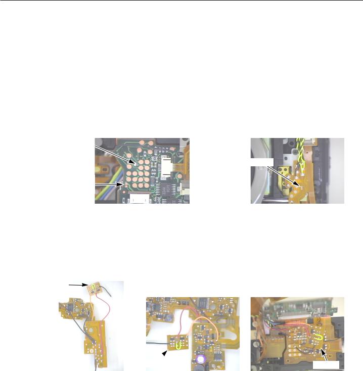
1) Camera Operation After Bottom Cover Removal
After the bottom cover is removed, the main switch cannot be turned on. To work around this, short-circuit the short pad on the main board. This will enable camera operation.
When reattaching the bottom cover, be sure to completely remove the solder from the short pad.
2) Camera Operation After Top Cover Removal
After the top cover is removed, the X-sync contact will be open. In this state, releasing the shutter will result in an error. To work around this, short-circuit the X-sync contact pad on the DX flex. This will enable camera operation.
When reattaching the top cover, be sure to completely remove the solder from the short pad.
SPADRTCVDD pad (Always shorted)
X-sync contact pad (DX)
Main SW pad (Open when bottom cover is attached.)
Fig. 3-1 Main SW pad. |
Fig. 3-2 X-sync contact pad. |
1.3 ABOUT THE DC/DC FLEX UNIT
1) DC/DC Flex Unit (Interim)
Applicable Units: DC/DC unit classification No. C and before A small flex is attached.
Small flex
Small flex |
Small flex |
|
Fig. 3-3 Interim DC/DC (top) |
Fig. 3-4 Interim DC/DC |
Fig. 3-5 Installed state. |
|
(bottom) |
|
2) DC/DC flex unit (permanent)
Applicable Units: DC/DC unit classification No. D onward
The small flex and lead wire will be eliminated.
3-2
Part 3: Repair Information
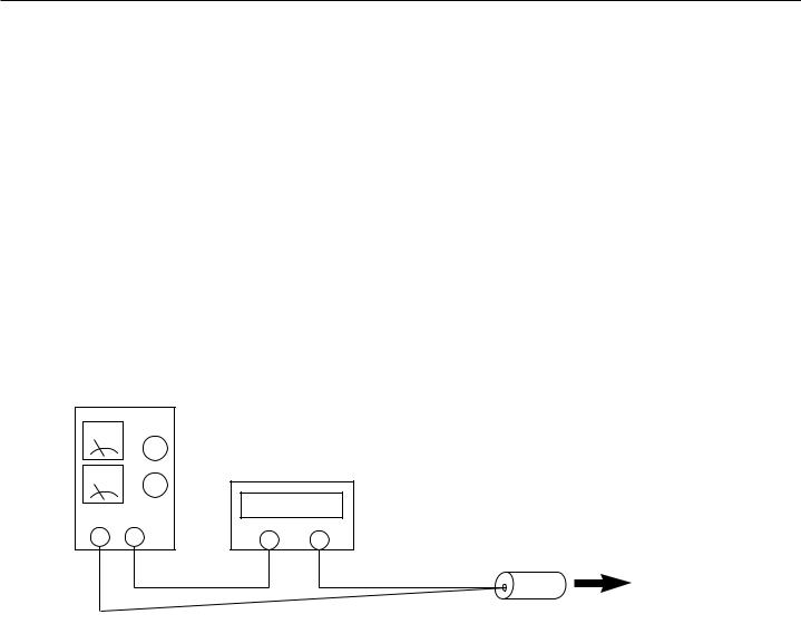
1.4 POWER CURRENT CONSUMPTION
1) Current Consumption Standards
Lens |
: EF 50mm f/1.8 |
|
|
Power source |
: Constant voltage 5.4 V, 0.7 ohm |
|
|
Ambient conditions : Room temperature, normal humidity (below 60%) |
|||
Camera Status |
|
Standard |
Actual Measurement |
|
|
|
|
Standby |
|
100 µA or lower |
Approx. 40 µA |
Lock |
|
100 µA or lower |
Approx. 30 µA |
SW1-ON |
|
400 mA or lower |
Approx. 300 mA |
Battery check |
|
1500 mA or lower |
-- |
Self-timer operation |
420 mA or lower |
Approx. 300 mA |
|
*Note: The Actual Measurement is taken from the initial lot of the camera’s mass production. It may differ slightly with subsequent lots.
Constant-Voltage Power Source
Digital tester or other ammeter
- + + -
Tool battery
To camera
Fig. 3-6 Power current consumption measuring method.
3-3

Part 3: Repair Information
1.5 TOOLS AND EXPENDABLES LIST
The following tools and materials are required for camera reassembly and adjustment.
1) Tools List |
|
|
|
New |
Tool |
Part No. |
Purpose |
|
|
|
|
|
HS-I/F |
CY9-7082-000 |
Electrical adjustment |
|
Memory expansion |
CY9-7082-002 |
Memory expansion for HS-I/F |
|
Multiple Tool 2 |
CY9-7099-000 |
Electrical adjustment |
|
Contack adapter (SLR) |
CY9-7099-002 |
For Multiple Tool 2 |
|
EF-8000 Multi-Camera Tester |
CY9-7073-000 |
Shutter AE adjustment |
|
EF-5000 Multi-Camera Tester |
CY9-7086-000 |
Shutter AE adjustment |
|
AE sensor (EF-8000) |
CY9-7102-001 |
AE adjustment |
|
AE sensor (EF-5000) |
CY9-7102-002 |
AE adjustment |
|
Shutter sensor (EF-8000) |
CY9-7104-001 |
Shutter adjustment |
|
Shutter sensor (EF-5000) |
CY9-7104-002 |
AE adjustment |
|
Direct sensor (EF-8000) |
CY9-7105-001 |
Flash metering adjustment |
|
Direct sensor (EF-5000) |
CY9-7105-002 |
Flash metering adjustment |
|
Stable DC power source |
|
Electrical adjustment |
|
Infrared dark box (NTSC) |
CY9-6152-000 |
Jammed film removal |
|
(PAL) |
CY9-6153-000 |
|
|
Monitor (with video IN terminal) |
Commercially available |
|
|
Dial gauge |
CY9-1001-006 |
Flange focal distance adjustment |
|
Dial gauge (0.001 mm) |
CY9-7094-000 |
Flange focal distance adjustment |
|
Connecting rod (0.001 mm) |
CY9-7094-002 |
Flange focal distance adjustment |
|
Point (ruby tip) (0.001 mm) |
CY9-7094-003 |
Flange focal distance adjustment |
|
Dial Gauge Holder-2 |
CY9-1001-004 |
Flange focal distance adjustment |
|
2 mm adaptor ring |
CY9-1001-008 |
Flange focal distance adjustment |
|
Block gauge (44.14 mm) |
CY9-1001-007 |
Flange focal distance adjustment |
|
Optical flat |
CY9-1001-003 |
Flange focal distance adjustment |
|
Parallel glass |
CY9-1024-000 |
Flange focal distance adjustment |
|
AF tool lens |
CY9-1072-001 |
AF precision adjustment |
|
Video light |
Commercially available |
AF adjustment |
|
Flashmeter |
Commercially available |
Flash metering adjustment |
|
Penlight |
Commercially available |
SPC positioning |
|
Tripod |
Commercially available |
|
|
Dark box |
Commercially available |
|
|
Tester |
Commercially available |
Voltage measurement |
|
Best Focus tool (PAL) |
CY9-7110-000 |
AF check and adjustment |
|
Best Focus tool (NTSC) |
CY9-7110-001 |
AF check and adjustment |
|
Focus mirror |
CY9-7110-002 |
AF check and adjustment |
|
AF standard charts (set of 3) |
CY9-1124-000 |
AF adjustment |
|
Inhibit voltage tool kit |
CY9-1101-000 |
Inhibit voltage adjustment |
|
PDB tool battery kit |
CY9-1104-000 |
Inhibit voltage adjustment |
3-4
|
|
|
|
Part 3: Repair Information |
|
|
|
|
|
||
|
2) Charts and Locally Fabricated Tools |
|
|
||
New |
Tool |
Part No. |
Purpose |
||
|
|
|
|
|
|
|
|
18%-reflectance gray card |
|
Flash metering adjustment |
|
|
|
3D chart |
*See the EF 300mm f/4.0L IS lens manual |
||
|
|
SPC positioning mask |
Locally fabricated |
|
|
|
|
X-sync shoe |
Locally fabricated |
X-sync time lag check |
|
|
|
Parallax chart |
Locally fabricated |
Viewfinder parallax adjustment |
|
|
|
Tool battery |
See the EOS-1N Service Manual. |
||
*For details, see “About Custom Tools.”
3)Other Products for Testing
New |
Tool |
Part No. |
Purpose |
|
EF 50mm f/1.8 production lens |
|
Camera operations, adjustments, |
|
|
|
checking |
|
Speedlite (A-TTL with 300EZ, 540EZ, etc.) |
Flash metering adjustment |
|
|
Speedlite (E-TTL with 380EX, 550EX, etc.) |
Flash metering adjustment |
|
|
Power Drive Booster PDB-E2 |
Product |
Inhibit voltage adjustment |
|
Ni-MH battery |
Product |
|
|
Ec-D Laser Matte with grid or |
|
|
|
Ec-H Laser Matte with scale |
Product |
SI adjustment |
4) Expendables List |
|
|
|
New |
Tool |
Part No. |
Purpose |
|
|
|
|
|
Light-shield tape |
CY9-4026-000 |
M2 motor |
|
Tape (No. 315) |
CY9-4031-000 |
DX unit, film transport unit |
|
Double-sided tape |
CY9-4034-000 |
Body |
|
Aron Alpha 201 |
CY9-8007-000 |
Securing SPD and SI in place |
|
Arontite L |
CY9-8008-000 |
For screw heads |
|
Three Bond 1401C |
CY9-8011-000 |
Setscrews |
|
UTLM-10 |
CY9-8031-000 |
Mirror parts |
|
Silicon KE-347B |
CY9-8064-000 |
Water resistance |
|
Grease H-26 |
CY9-8079-000 |
Dial unit and other parts |
|
IF10 |
CY9-8088-000 |
Mount spring |
|
Lube, Barrierta SJF-102, Grease |
CY9-8100-000 |
Release contact |
|
Paint, MM-010A Oil-retardant |
CY9-8101-001 |
Prevention of oil oozing under the mount |
|
Longenest Lambda A-74 |
CY9-8102-000 |
M2 gear shafts |
|
Diabond 1663B |
CY9-8110-000 |
Adhesive for parts |
|
Longenest Lambda NK-74C |
CY9-8117-000 |
Shafts and friction parts |
* Cemedine Super X No. 8008 Black CY9-8118-000 |
Mount ring and other parts |
||
* |
Nox Guard ST-420 |
CY9-8123-000 |
Parts assembly |
* |
Longenest Lambda NFH-743C |
CY9-8125-000 |
Front cover’s friction surfaces |
3-5
Part 3: Repair Information
1.6 LOCALLY FABRICATED PARTS |
|
|
|
|
||||
1) SI Adjustment Chart |
|
145mm |
|
|
||||
|
|
|
||||||
As shown in the figure, affix five white |
|
|
||||||
|
|
|
|
|||||
pieces of reflective paper on a black |
|
|
|
|
|
|
|
|
|
|
|
|
|
|
|
||
cardboard. (Sample provided at the |
|
|
|
|
|
|
|
|
end of the manual.) |
|
|
|
|
|
|
|
|
|
|
|
|
|
|
|
|
21.2mm |
|
70.9mm |
|
|
|
|
|
|
|
|
|
|
|
|
|
|
||
|
|
|
|
|
|
|
|
|
|
|
|
|
|
|
|
|
|
|
|
|
|
|
|
|
|
|
|
|
|
|
|
14.3mm |
|||
|
|
|
87mm |
|
|
|||
|
|
|
|
|
|
|
|
|
Fig. 3-7 SI Adjustment Chart.
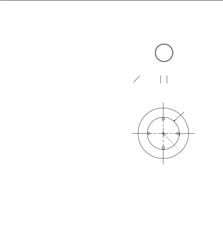
2) SPD Positioning Mask
On a low-reflectance, black sheet of
paper, make holes as shown in the fig- ø 57mm ure below.
 ø 4~6mm
ø 2~3mm
Fig. 3-8 SPD positioning mask.
3) X-sync Shoe
This is for measuring the X-sync time lag.
As shown in the figure, attach a 4.7 k ohm resistor between the CCC line and GND on the hot shoe.
Fig. 3-9 X-sync shoe.
3-6

Part 3: Repair Information
<Memo>
3-7
This page intentionally left blank

Part 3: Repair Information
2. DISASSEMBLY AND REASSEMBLY
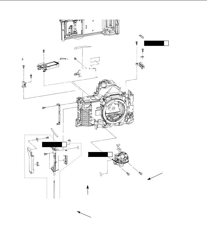
2.1 EXTERNAL COVERS
x2 |
CAUTION |
|
1 |
R= 3mm |
|
|
|
x2
Barrierta SJF-102 R= 10mm Apply a thin film on
the release pin’s friction surface.
R= 10mm
NOTE 2
|
|
|
|
|
|
|
|
|
|
|
|
|
|
(2) |
|
|
|
|
|
|
|
|
|
|
R= 3.5mm |
|
|
|
|
|
|
|
|
|
|
|
|
|
|
|
|
|
|
|
|
|
|
|||
|
|
|
|
|
|
|
|
|
|
|
|
NOTE |
1 |
|
|
|
|
|
|
|
|
|
Do not scratch. |
|
|
|
|
|
|
|
|
||
|
|
|
|
|
|
|
|
|
|
|
|
|
|
|
|
|
(1) |
|
|
|
|
|
|
|
|
|
|
|
|
|
|
|
|
|
|
|
|
|
|
|
|
|
|
|
|
|
|
|||
|
|
|
|
|
Nox Guard ST-420 |
|
|
|
|
|
||||||
|
|
|
|
|
|
Apply along the inside |
|
|
|
|
|
|
||||
|
|
|
|
|
|
corner. |
|
|
|
|
|
|
||||
|
|
|
|
|
|
|
|
|
|
|
|
|
|
|
|
|
|
|
|
|
R= 3mm |
|
|
|
|
|
|
|
|
|
x2 |
||
|
|
|
|
|
|
|
|
|
|
|
|
|
|
|
|
|
|
(3) |
|
|
|
|
|
|
|
|
|
|
|
|
|
R= 4mm |
|
|
|
x4 |
R= 3.5mm |
|
|
|
R= 4mm |
|
|
|
R= 7mm
x2
R= 3.5mm
x2 CAUTION 
 1
1
(4)
CAUTION 
 1
1
x2
R= 7mm
R= 6mm
CAUTION 
 1
1
x2
R= 4mm
Diabond 1663B Affix the nameplate.
Fig. 3-10 External covers.
3-8
Part 3: Repair Information
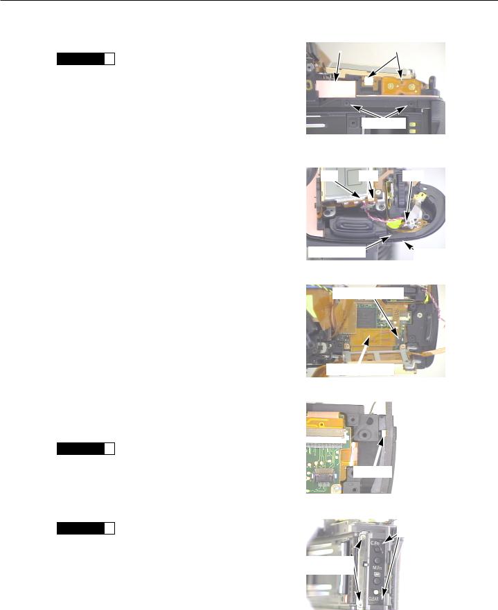
<REMOVAL PROCEDURE>
CAUTION  1 Assembly location of water-resistant parts (Do not lose)
•Front cover screws (Front x 2, bottom x 2)
•Top cover left and right screws at bottom
•Eyepiece shutter lever
•Eyepiece adjusting dial
(1)Remove the grip unit.
(2)Remove the front cover assembly.
•Remove the eight screws (front x 2, right x 2, bottom x 2, remote control side x 1, film chamber x 1).
•Peel off the left front panel cover on the latch cover.
•Disconnect the remote control flex from the connector.
NOTE 1 • To remove the front cover assembly, start with the grip side.
(3)Removal of bottom cover assembly
•Remove the eight screws (D) securing the bottom cover.
•Disconnect the main flex from the connector.
NOTE |
2 |
• Turn on the main switch by short-cir- |
|
|
cuiting the pad (shown on the right) on |
|
|
the main flex. |
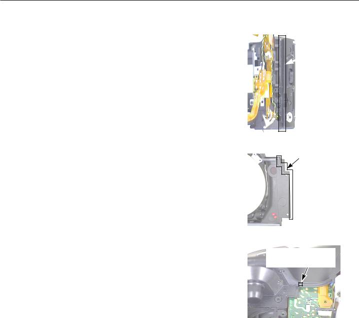
(4)Removal of top cover assembly
•Remove the following screws: Under left and right strap rings (2) Back screws (2)
Eyepiece shutter lever Eyepiece adjusting dial
Underside of shutter button grip overhang screws (2)
•Remove the solder on the two lead wires connected to the DX flex.
•Remove the TOP flex from the connector.
•With the top cover removed, the shutter’s X-sync contact will be open. Releasing the shutter will therefore result in error. To prevent this error, short the X-sync pad (Fig. 3-13).
Remote control flex connector
Fig. 3-11 Remote control flex connector.
Main switch pad
Fig. 3-12 Main SW pad
Black (SH-X GND) Yellow (SH-X)
X-sync pad
Fig. 3-13 Top cover lead wires.
TOP flex connector
Fig. 3-14 Top cover connector.
3-9
Part 3: Repair Information
<REASSEMBLY CAUTIONS>
1.Check all the short pads.
2.Make sure none of the lead wires protrude or get pinched by the covers.
3.If the silicon bond on the latch cover side has come off, apply Silicon Bond KE-347B.
4.Apply a little Nox Guard ST-420 on the side (grip) of the front cover. There must be no excess that oozes outside. After applying it, do not wipe it with a solvent. Doing so will degrade its waterresistance properties.
5.Use Silicon Bond KE-347B to completely fill in the gap between the top cover and dial base plate.
Apply Silicon
 Bond KE-347B.
Fig. 3-15 Latch cover.
Apply Nox
Guard ST-420
Fig. 3-16 Front cover.
Apply Silicon Bond KE-347B in the gap between the top cover and dial base plate.
Fig. 3-17 Top cover.
3-10

Part 3: Repair Information
<Memo>
3-11
Part 3: Repair Information
2.2 PALM SWITCH HOLDER
x3
R= 4.5mm
x2
R= 4mm
R= 6mm
(2)
(3)
R= 5.5mm
(5)
x2
R= 3.5mm
CAUTION 
 4
4
R= 2.5mm
x2
R= 5mm
(6)
Normally, disassembly is unnecessary.
CAUTION 
 3
3
Palm switch The notched end must be upward.
Longenest Lambda NK-74C Apply a thin coat on the entire shaft.
Fig. 3-18 Palm switch holder.
(1)
CAUTION 
 2
2
R= 6mm
R= 5.5mm
(5)
(4)
Barrierta SJF-102 Apply a thin coat on the release pin’s friction surface.
R= 3.5mm
R= 5mm
3-12
Part 3: Repair Information
<DISASSEMBLY PROCEDURE>
(1) Removal of Camera Back Assembly
CAUTION  2 • Be careful not to damage the shutter curtains.
(2)Removal of Back Switch Base
•Detach the two flex from the back switch.
•Remove the two screws.
•Detach the back switch and also remove the right body seal.
(3)Removal of Outside LCD Unit
•Remove the two lead wires (red, gray) on the right of the Outside LCD.
•Remove the three screws.
•Disconnect the connector from the main board unit.
(4)Removal of Dial Unit
•Disconnect the black lead wire from the shutter release arm.
•Peel off the hinge cover seal (top) from the dial unit.
•Disconnect the AD switch flex from the connector.
•Remove the two screws.
•While peeling off the grip seal on the palm switch holder, remove the dial unit.
(5)Removal of Left and Right Strap Ring Screws
•Remove the two screws.
CAUTION  3 • Be careful not to lose or bend the GND plate under the right ring.
(6)Removal of Palm Switch Holder
•Remove the camera back hinge screws (2).
•Remove the palm switch holder (2 screws).
CAUTION  4 • The palm switch holder might be difficult to remove due to the silicon bond applied under the holder on the camera chassis.
See next page about the application area.
Right body seal |
|
Remove flex |
Two screws
Fig. 3-19 Back switch.
Red |
Gray |
Black |
Hinge cover seal |
Grip seal |
|
Fig. 3-20 Dial lead wires.
AD switch connector
OLC unit connector
Fig. 3-21 Removal of OLC unit.
GND plate
Fig. 3-22 Right ring GND plate.
Palm switch holder screws
Camera back hinge screw
Fig. 3-23 Palm switch holder.
3-13
 Loading...