


 Loading...
PUB. DIE-0494-000E
Digital Cinema Camera
Firmware ver. 1.0.4.1.00 (Z[) ver. 1.0.2.1.00 (])
Instruction Manual
Important Usage Instructions
WARNING
2TO REDUCE THE RISK OF ELECTRIC SHOCK AND TO REDUCE ANNOYING INTERFERENCE, USE THE RECOMMENDED ACCESSORIES ONLY.
COPYRIGHT WARNING
Unauthorized recording of copyrighted materials may infringe on the rights of copyright owners and be contrary to copyright laws.
FCC NOTICE |
in a commercial environment. This equipment |
|
Digital Cinema Camera, EOS C700 Systems. |
generates, uses, and can radiate radio |
|
This device complies with Part 15 of the FCC |
frequency energy and, if not installed and used |
|
Rules. Operation is subject to the following two |
in accordance with the instruction manual, may |
|
conditions: (1) This device may not cause |
cause harmful interference to radio |
|
harmful interference, and (2) this device must |
communications. Operation of this equipment in |
|
accept any interference received, including |
a residential area is likely to cause harmful |
|
interference that may cause undesired |
interference in which case the user will be |
|
operation. |
required to correct the interference at his own |
|
NOTE: This equipment has been tested and |
expense. |
|
Do not make any changes or modifications to |
||
found to comply with the limits for a Class A |
||
the equipment unless otherwise specified in the |
||
digital device, pursuant to part 15 of the FCC |
||
manual. If such changes or modifications should |
||
Rules. These limits are designed to provide |
||
be made, you could be required to stop |
||
reasonable protection against harmful |
||
operation of the equipment. |
||
interference when the equipment is operated |
||
|
||
|
|
Only for European Union and EEA (Norway, Iceland and Liechtenstein)
These symbols indicate that this product is not to be disposed of with your household waste, according to the WEEE Directive (2012/19/EU), the Battery Directive (2006/66/EC) and/or national legislation implementing those Directives.
 If a chemical symbol is printed beneath the symbol shown above, in accordance with the Battery Directive, this indicates that a heavy metal (Hg = Mercury, Cd = Cadmium, Pb = Lead) is present in this battery or accumulator at a concentration above an applicable threshold specified in the Battery Directive.
This product should be handed over to a designated collection point, e.g., on an authorized one-for-one basis when you buy a new similar product or to an authorized collection site for recycling waste electrical and electronic equipment (EEE) and batteries and accumulators. Improper handling of this type of waste could have a possible impact on the environment and human health due to potentially hazardous substances that are generally associated with EEE. Your cooperation in the correct disposal of this product will contribute to the effective usage of natural resources.
For more information about the recycling of this product, please contact your local city office, waste authority, approved scheme or your household waste disposal service or
visit www.canon-europe.com/weee, or www.canon-europe.com/battery.
CAN ICES-3(A)/NMB-3(A)
WARNING
This is a class A product. In a domestic environment this product may cause radio interference in which case the user may be required to take adequate measures.

3
Trademark Acknowledgements
•SD, SDHC and SDXC Logos are trademarks of SD-3C, LLC.
•Canon is an authorized licensee of the CFast 2.0™ trademark, which may be registered in various jurisdictions.
•Microsoft and Windows are trademarks or registered trademarks of Microsoft Corporation in the United States and/or other countries.
•Apple and macOS are trademarks of Apple Inc., registered in the U.S. and other countries.
•The Apple ProRes codec module is used under license from Apple Inc.
•Avid and Media Composer are trademarks or registered trademarks of Avid Technology, Inc. or its subsidiaries in the United States and/or other countries.
•IDX, the IDX logo, V-mount are trademarks or registered trademarks of IDX Company, Ltd.
•Wi-Fi is a registered trademark of the Wi-Fi Alliance.
•Wi-Fi Certified, WPA, WPA2, and the Wi-Fi Certified logo are trademarks of the Wi-Fi Alliance.
•WPS as used on the camera’s settings, onscreen displays and in this manual signifies Wi-Fi Protected Setup.
•The Wi-Fi Protected Setup Identifier Mark is a mark of the Wi-Fi Alliance.
•JavaScript is a trademark or registered trademark of Oracle Corporation, its affiliates or subsidiaries in the United States and other countries.
•HDMI, the HDMI logo and High-Definition Multimedia Interface are trademarks or registered trademarks of HDMI Licensing LLC in the United States and other countries.
•DaVinci Resolve™ is the trademark of Blackmagic Design Pty Ltd.
•Other names and products not mentioned above may be trademarks or registered trademarks of their respective companies.
•This device incorporates exFAT technology licensed from Microsoft.
•This product is licensed under AT&T patents for the MPEG-4 standard and may be used for encoding MPEG-4 compliant video and/or decoding MPEG-4 compliant video that was encoded only (1) for a personal and noncommercial purpose or (2) by a video provider licensed under the AT&T patents to provide MPEG-4 compliant video. No license is granted or implied for any other use for MPEG-4 standard.
•ANY USE OF THIS PRODUCT OTHER THAN CONSUMER PERSONAL USE IN ANY MANNER THAT COMPLIES WITH THE MPEG-2 STANDARD FOR ENCODING VIDEO INFORMATION FOR PACKAGED MEDIA IS EXPRESSLY PROHIBITED WITHOUT A LICENSE UNDER APPLICABLE PATENTS IN THE MPEG-2 PATENT PORTFOLIO, WHICH LICENSE IS AVAILABLE FROM MPEG LA, L.L.C., 250 STEELE STREET, SUITE 300, DENVER, COLORADO 80206.

Highlights of the Camera
The Canon Digital Cinema Camera EOS C700 / EOS C700 PL / EOS C700 GS PL has been designed to meet the demanding needs and highest expectations of industry professionals. The following are just some of the many features that will help turn your creative vision into reality.
4
4K Recording System with Cinema Quality
Advanced 4K-compatible sensor
The camera features a Super 35mm-equivalent CMOS sensor ([]) or a Super 35mm-equivalent CMOS sensor with global electronic shutter (]). With the new sensor’s effective pixel count of 8.85 megapixels (4096x2160)1 and the new Triple DIGIC DV5 imaging engine, the camera offers a center resolution of 1,800 TV lines2. Thanks to Canon’s high sensitivity and low-noise technology, the camera can record at a wide range of sensitivity settings, from ISO 160 to ISO 256003. Using one of the Canon Log gamma curves you can make the most of the image sensor’s characteristics to obtain a very wide dynamic range.
1 When the resolution is set to 4096x2160.
2 Varies depending on the lens used.
3With the Zor [model. The ISO speed range can be extended to ISO 100 (Z[) or ISO 400 (]) on one end, and ISO 102400 on the other.
Interchangeable lenses
With three models featuring different lens mounts and shutter mechanisms, the camera offers the freedom to use the lens you want in order to achieve exactly the look you want. With the model featuring an EF lens mount (Z), you can use over 100 high-quality lenses from Canon’s EF and EF Cinema lens series. Whereas the models featuring a PL lens mount ([]) let you use a variety of industry-standard PL lenses.
Using the global shutter model (]), you can shoot fast-moving subjects without worrying about rolling shutter distortions or artifacts. And using compatible broadcast lenses4 and EF Cinema lenses (A224), you will be able to control the aperture and zoom using the camera5. The camera also supports the use of anamorphic lenses
(A122).
4The optional MO-4E or MO-4P B4 Mount Adapter is required.
5Depending on the lens used, you may need to connect the 12-pin camera interface cable to the camera.
Choose your format – XF-AVC or ProRes
Using the XF-AVC format, the camera can use two codecs (H.264 Intra-frame and H.264 Long GOP) so you can select the video configuration from YCbCr 4:2:2, 10 bit, RGB 4:4:4, 10 or 12 bit, or YCbCr 4:2:0, 8 bit, to suit your creative needs. Using Apple’s ProRes format, you have the choice
between the 10-bit ProRes 422 HQ codec and the 12-bit ProRes 4444 codec.
4K video RAW recording and output
You can use a recorder docked with the camera6 to record RAW 4K video. At the same time, you can apply a LUT that meets the ACES standard to video output from the MON. terminals or the HDMI OUT terminal to use this video output for on-set color grading (A22).
6For details about docking the CDX-36150 Recorder with the camera and using it to record, refer to Codex Recorder – Guide for the EOS C700 models (separate PDF file).
Recording media
The camera features two CFast card slots and an SD card slot. It records main recording clips (XF-AVC or ProRes) on the CFast cards. When you insert two CFast cards in the camera, the camera can record simultaneously on both cards (double slot recording), or it can switch automatically to recording on the other CFast card when a CFast card becomes full (relay recording) (A52). In addition to the main recording, you can activate the simultaneous sub recording (A71). Sub recording clips can be recorded on the CFast card (XF-AVC Intra) or on the SD card (XF-AVC Proxy).
Operability and Adaptability
Expandable modular design
The sturdy camera body was designed with ease of use and expandability in mind. It features a multitude of screw holes of different diameters on its top and bottom plates to offer a large number of options for attaching additional accessories to the camera.
Using the optional EVF-V70 OLED Electronic Viewfinder (17 mm (0.7 in.), 1920x1080 pixels/ approx. 6.22 million dots), OU-700 Remote Operation Unit, SU-15 Shoulder Support Unit and SG-1 Shoulder Style Grip Unit, you can quickly optimize the camera for one-person operation or for team operation from both sides, depending on your needs (A38).
The camera offers assignable buttons and a customizable USER screen (using the screen buttons) that you can customize to your preferences from a large number of convenient functions
(A127). Optional accessories offer additional assignable buttons. Assign functions that you use often to the assignable buttons you find most

convenient to personalize the camera to your needs and preferences.
Power options
You can power the camera using commercially available V-mount batteries or power sources connected to the DC IN 12V terminal (XLR 4-pin jack) (A26). The camera also offers power outputs (24 V DC, 12 V DC or D-Tap) to supply power to connected accessories (A28).
Remote operation
You can attach the optional RC-V100 Remote Controller to the camera to control it from a distance. The remote controller lets you control a wide range of camera settings (A123).
Connect the camera to a network (Wi-Fi7 or wired) to operate it remotely from a network device using the Browser Remote application (A168). Browser Remote lets you check the live view image from the camera, adjust main camera settings and change the metadata embedded with XF-AVC clips.
7The optional WFT-E6 or WFT-E8 Wireless File Transmitter is required.
Versatile Artistic Expression
Slow & fast motion (A68)
Change the shooting frame rate to create a slow motion effect (up to 1/10 of the normal speed) or fast motion effect (up to 60x the normal speed).
Custom picture settings
Select one of the preset color settings or set the combination of gamma curve, color space and color matrix that you wish to use. Then, you can adjust a number of other image-related parameters in detail. With wide color space options such as BT.2020 Gamut and Cinema Gamut, and the new Canon Log 3 gamma curve, which keeps the characteristics of the Canon Log gamma while expanding the dynamic range, you can be sure that the camera covers your creative needs.
Other Functions
IP streaming and FTP transfer
Connect the camera to a network (Wi-Fi8 or wired) to stream live transmissions or breaking images via IP and to transfer sub recordings (XF-AVC Proxy clips) from the SD card to a remote server using the FTP protocol.
8The optional WFT-E6 or WFT-E8 Wireless File Transmitter is required.
Software for aiding production workflow
Canon XF Utility (A160) lets you copy the XF-AVC clips you recorded from your recording media to a computer, play back the clips and organize them. Cinema RAW Development (A160) can develop RAW data and export it as a standard file type such as DPX or OpenEXR. You can also import an EDL to recreate an edit created on NLE software. This helps
make a smooth transition to the color grading process.
Dual Pixel CMOS AF and autofocus functions (Zonly)
The camera features Dual Pixel CMOS AF technology, which covers almost 80% of the 2K or 4K recording area, and offers various autofocus
functions (A89): continuous AF, one-shot AF (to 5 use autofocus only when you choose) or
AF-boosted MF (to let you focus manually most of the way and let the camera finish focusing automatically). Using AF-boosted MF the camera does not perform unreliable focus adjustments, resulting in a smoother focusing operation than with continuous AF.
ZThe camera also features face detection (A96), tracking of moving subjects (A97) and the Dual Pixel Focus Guide function (A90), a visual, intuitive guide that you can use to check if the image is in focus. This can be very helpful to ensure you always get amazingly sharp 4K video.
Assistance functions
The camera offers a number of assistance functions, such as peaking and magnification (A90), onscreen markers (A98), zebra patterns (A99), B&W image (A193), false color display (A100) and waveform monitor (A115) that you can display on an optional viewfinder or on external monitors connected to the MON. terminals or HDMI OUT terminal. When using a logarithmic gamma curve, you can also apply a LUT (A154) for easier monitoring.
Other improved features
•Five levels of ND filter (A78).
•Z[Flash band correction (A75).
•In-camera correction for peripheral illumination and chromatic aberration (A47).
•Built-in level (electronic horizon) (A40).
•Illuminated buttons for night time or black-out operation.
•Monaural built-in microphone for note taking.
•Customizable onscreen displays (A139).
•Three sets of customizable My Menu submenus (A35).
•Menu settings file that can be saved in the camera or on an SD card to restore all the menu settings or replicate them perfectly on another C700 series camera (A140).
•Improved clip name format with more information for easier identification and organization of clips (A62).
•Metadata and geotagging (A118, 120, 178).

Table of Contents
6
1. Introduction 11
About this Manual 11 |
|
|
Conventions Used in this Manual 11 |
||
Supplied Accessories |
12 |
|
Names of Parts 13 |
|
|
Microphone Holder 18 |
||
Handle Unit |
18 |
|
Clamp Base |
19 |
|
EVF-V70 OLED Electronic Viewfinder |
||
(optional) 20 |
|
|
4K Workflow Overview |
21 |
|
Color Grading with the ACES Workflow 22 |
||
2. Preparations 23
Preparing the Backup Battery 23 |
|
|
|
Removing an Extension Module |
23 |
|
|
Inserting the Lithium Button Battery 24 |
|
||
Installing an Extension Module 24 |
|
||
Preparing the Main Power Supply |
26 |
|
|
Acceptable Power Sources 26 |
|
|
|
Using a Battery 26 |
|
|
|
Using the DC IN 12V Terminal 27 |
|
||
Checking the Camera’s Power Levels 27 |
|
||
Power Outputs 28 |
|
|
|
Turning the Camera On and Off |
28 |
|
|
Date, Time and Language Settings 29 |
|
||
Setting the Date and Time 29 |
|
|
|
Changing the Language |
29 |
|
|
Changing Camera Settings with the Screen |
|
||
Buttons 30 |
|
|
|
Using the Menus 32 |
|
|
|
Selecting an Option from the Camera Menu |
32 |
||
Selecting an Option from the Monitoring Menu |
33 |
||
Using the Customized Submenu (My Menu) |
35 |
||
Preparing the Camera 38 |
|
|
|
Shooting Configurations |
38 |
|
|
Attaching the Handle Unit |
40 |
|
|
Using a Tripod 40 |
|
|
|
Using the Optional EVF-V70 OLED Electronic |
|
||
Viewfinder 41 |
|
|
|
Attaching the Microphone Holder |
43 |
|
|
Preparing the Lens 44 |
|
|
|
In-Camera Lens Correction 47 |
|
|
|
Preparing Recording Media |
48 |
|
Compatible Recording Media 48 |
||
Inserting a CFast Card |
49 |
|
Removing a CFast card |
49 |
|
Inserting and Removing an SD Card 50 |
||
Initializing Recording Media |
51 |
|
Switching Between the CFast Card Slots 52 |
||
Relay Recording and Double Slot Recording 52 |
||
Checking the Remaining Recording Time on |
||
Recording Media |
53 |
|
Recovering Clips 53 |
|
|
Adjusting the Black Balance |
54 |
|
3. Recording 55
Recording Video 55
Recording 55
Onscreen Displays on the HOME Screen 57 Onscreen Displays on the Shooting Screen 59 Setting the Clip File Name 62
Using the Fan 63
Video Configuration: Video Format, System
Frequency, Frame Rate, Resolution and Bit
Rate 65
Selecting the Main Recording Format 65
Selecting the System Frequency 65
Selecting the Frame Rate 65
Selecting the Resolution and Color Sampling
Settings 65
Selecting the Bit Rate 66
Slow & Fast Motion Recording 68
Simultaneous Sub Recordings 71
Changing Main Camera Functions with the FUNC Button 73
Using the Direct Setting Mode 73
Shutter Speed 74
Changing the Shutter Speed Mode and Value 75
ISO Speed/Gain 76
Changing the ISO Speed or Gain Value 77 Using the Control Dial 77
ND Filter 78

Adjusting the Aperture |
79 |
|
|
||
Manual Aperture 80 |
|
|
|
||
Momentary Automatic Aperture - Push Auto |
|
||||
Iris 81 |
|
|
|
|
|
Automatic Aperture |
81 |
|
|
||
Exposure Compensation - AE Shift 82 |
|
||||
Light Metering Mode |
82 |
|
|
||
Gamma Curve and Main Color Settings 84 |
|
||||
Preset Color Settings |
84 |
|
|
||
White Balance |
86 |
|
|
|
|
Selecting the White Balance Mode/Setting 86 |
|||||
Auto White Balance (AWB) 87 |
|
|
|||
Registering a Custom White Balance 87 |
|
||||
Adjusting the Color Temperature or CC Value |
88 |
||||
Renaming User-Set White Balance Settings |
88 |
||||
Adjusting the Focus |
89 |
|
|
||
Manual Focus |
90 |
|
|
|
|
ZOne-Shot AF |
92 |
|
|
||
ZAF-Boosted MF |
93 |
|
|
||
ZContinuous AF |
93 |
|
|
||
ZChanging the AF Frame Size and |
|
||||
Position |
95 |
|
|
|
|
ZFace Detection |
96 |
|
|
||
ZTracking a Specific Subject 97 |
|
||||
Onscreen Markers, Zebra Patterns and False |
|
||||
Color 98 |
|
|
|
|
|
Displaying Onscreen Markers |
98 |
|
|||
Displaying Zebra Patterns 99 |
|
|
|||
Using the False Color Display |
100 |
|
|||
Setting the Time Code |
101 |
|
|
||
Selecting the Time Code Mode |
101 |
|
|||
Selecting Drop or Non-Drop Frame 102 |
|
||||
Putting the Time Code Display on Hold 102 |
|
||||
Setting the User Bit |
104 |
|
|
||
7
Synchronizing with an External Device 105 |
|||
Connecting an External Device |
105 |
||
Reference Video Signal Input (Genlock |
|||
Synchronization) |
106 |
|
|
Time Code Signal Input |
106 |
|
|
Reference Video Signal Output |
107 |
||
Time Code Signal Output 107 |
|
||
Recording Audio |
108 |
|
|
Audio Settings and Recorded Audio |
|||
Channels |
108 |
|
|
Connecting an External Microphone or External
Audio Input Source to the Camera |
109 |
|||
Setting the Audio Input Type for the INPUT 1/ |
||||
INPUT 2 Terminals |
110 |
|
|
|
Selecting the Audio Input Source for Audio |
||||
Channels |
111 |
|
|
|
Adjusting the Audio Recording Level |
111 |
|||
Additional Settings for External Analog |
|
|||
Microphones 112 |
|
|
|
|
Monitoring the Audio with Headphones |
113 |
|||
Colors Bars/Audio Reference Signal |
114 |
|
||
Color Bars 114 |
|
|
|
|
Audio Reference Signal |
114 |
|
|
|
Waveform Monitor 115 |
|
|
|
|
Displaying the Waveform Monitor 115 |
|
|||
Configuring the Waveform Monitor |
115 |
|
||
Adding an $Mark or %Mark while |
|
|
||
Recording |
117 |
|
|
|
Using Metadata |
118 |
|
|
|
Setting a User Memo Created with Canon XF |
||||
Utility 118 |
|
|
|
|
Entering Information About the Recording 119 |
||||
Recording GPS Information (Geotagging) |
120 |
|||
Using Anamorphic Lenses |
122 |
|
|
|
Using the Optional RC-V100 Remote |
|
|
||
Controller |
123 |
|
|
|
Taking Photos 125 |
|
|
|
|
Taking Photos |
125 |
|
|
|
Photo Numbering 125 |
|
|
|
|

8
4. Customization 127
Assignable Buttons and Customizable USER
Screen 127
Changing the Assigned Function and Using an
Assignable Button 127
Assignable Functions 128
Customizing and Using the USER Screen 130
Custom Picture Settings 131
Selecting Custom Picture Files 131
Editing a Custom Picture File’s Detailed
Settings 131
Resetting Custom Picture Files 132
Renaming Custom Picture Files 132
Protecting Custom Picture Files 132
Copying Custom Picture Files 133
Embedding Custom Picture Settings in a
Clip 133
Available Custom Picture Settings 134
Customizing Onscreen Displays 139
Saving and Loading Camera Settings 140
Saving Camera Settings 140
Loading Camera Settings 140
5. Playback 141
Playback 141
The PLAY (Playback Control) Screen 141 Selecting the Recording Media and Format to Play
Back 142 Playing Back Clips 142
Onscreen Displays During Playback 144
Clip/Photo Operations 145
Displaying Clip Information 145
Adding and Deleting $Marks or %Marks 146 Deleting Clips and Photos 147
Deleting the User Memo and GPS Information 147
Copying a Custom Picture File Embedded in a Clip 148
6. External Connections 149
Video Output Configuration 149
Main Recording Video Configuration and Video
Output Configuration from
the SDI OUT Terminals 149
Main Recording Video Configuration and Video
Output Configuration from the
MON. Terminals and HDMI OUT
Terminal 150
Playback Video Configuration and Video Output
Configuration by Terminal 151
Connecting to an External Monitor or Recorder 152
Connection Diagram 152
Using the SDI OUT Terminals 152 Using the MON. Terminals 153 Using the HDMI OUT Terminal 153 Applying a LUT to Video Outputs 154
Applying a User LUT to Video Outputs 156 Superimposing Onscreen Displays on Video
Outputs 158
Audio Output 159
Working with Clips on a Computer 160
Saving Clips to a Computer 160 Developing RAW Clips 160
7. Network Functions 161
About the Network Functions |
161 |
|
Connecting to a Wi-Fi Network |
162 |
|
Attaching the Optional Wireless File |
|
|
Transmitter 162 |
|
|
Camera Access Point 163 |
|
|
Connecting in Infrastructure Mode 163 |
|
|
Wi-Fi Protected Setup (WPS) |
164 |
|
Searching for Access Points |
165 |
|
Connecting to a Wired (Ethernet) Network |
166 |
|
Checking the Network’s Status and Settings 167 |
||
Checking and Changing Network Settings |
167 |
|
Browser Remote: Controlling the Camera from a Network Device 168
Setting Up Browser Remote 168 Starting Browser Remote 169 Using Browser Remote 171

9
IP Streaming 180
Preparations 180
Streaming Video over IP 181
FTP File Transfer 183
Preparations 183
Transferring Clips (FTP Transfer) 184
8. Additional Information 185
Setup Screens and Menu Options 185 |
|
||
Setup screens 185 |
|
|
|
Camera Menu and Monitoring Menu 188 |
|
||
Displaying the INFO Screens 201 |
|
||
Troubleshooting 204 |
|
|
|
List of Messages 209 |
|
|
|
Handling Precautions and Safety Instructions |
214 |
||
Maintenance/Others |
217 |
|
|
Optional Accessories |
218 |
|
|
Specifications 220 |
|
|
|
Appendix: Compatible Lenses and Functions |
224 |
||
Appendix: Camera Dimensions |
226 |
|
|
Approximate Recording Times |
231 |
|
|
Index 232 |
|
|
|

10
1 |
Introduction |
|
11
About this Manual
Thank you for purchasing the Canon EOS C700 / EOS C700 PL / EOS C700 GS PL. Please read this manual carefully before you use the camera and retain it for future reference. Should the camera fail to operate correctly, refer to Troubleshooting (A204).
Conventions Used in this Manual
• IMPORTANT: Precautions related to the camera’s operation.
• NOTES: Additional topics that complement the basic operating procedures.
•A: Reference page number.
•[]: Text that applies only to the model shown in the icon.
•The following terms are used in this manual.
“Monitoring screen” refers to the screen of a monitoring device (either the optional EVF-V70 OLED Electronic Viewfinder or an external monitor connected to one of the camera’s MON. terminals or HDMI OUT terminal). “SD card” refers to an SD, SDHC or SDXC memory card.
“Recording media” refers to CFast cards, SD cards and Codex Capture Drive 2.0 media.
•“The optional viewfinder” refers to the optional EVF-V70 OLED Electronic Viewfinder.
•“CDX-36150 Recorder” refers to the CDX-36150 Codex Recorder for Canon EOS C700.
•Photographs in the manual are simulated pictures taken with a still camera. Some screenshots have been altered to make them easier to read.
•Illustrations in the manual show the Canon EOS C700 camera with a Canon EF 50mm f/1.4 USM lens attached.
•The following style is used to represent menu selections. The first word (in the thick, bold typeface) indicates the button you need to press on the camera (in the case of “EVF”, on an optional EVF-V70 OLED Electronic Viewfinder connected to the camera) to open the required menu. For a detailed explanation on how to use the menus, refer to Using the Menus (A32). For a summary of all available menu options and settings, refer to the appendix Setup Screens and Menu Options (A185).
This indicates to press the MENU button on the camera or EVF button on the optional viewfinder.
Selecting the Main Recording Format
1 Open the [Main Rec Format] submenu.


 [Rec/Media Setup] (3) >[Main Rec Format]
• Alternatively, from the camera menu: 

 [S&F FPS] >[OPTIONS] >[Main Rec Format].
2 Select [XF-AVC (CFast)] or [ProRes (CFast)] and then press SET.
Brackets [ ] indicate text as it appears on the |
This arrow indicates a deeper |
camera’s control display or on the screen of a |
level in the menu hierarchy or |
monitoring device. |
the next step in a procedure. |
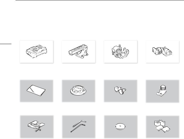
Supplied Accessories
Supplied Accessories
The following accessories are supplied with the camera.
12
Battery Adapter for |
|
Handle Unit |
|
Microphone Holder |
|
Clamp Base |
V-Mount Batteries1 |
|
|
|
|
|
|
|
|
|
|
|
|
|
|
|
|
|
|
|
|
Control Display Cover1 |
|
Body Cap1 |
|
Tape Measure Hooks1 (x 2) |
Extension Unit Attachment Bracket2 |
||
|
|
|
|
|
|
|
|
|
|
|
|
|
|
|
|
Reinforcement Plate for the |
Hex Wrenches (x 2) |
CR2025 Lithium Button Battery |
Rubber Anti-Slip Feet (x 4) |
CDX-36150 Recorder3 |
(for 0.64 cm, 1/4" screws/ |
|
|
including 0.64 cm, |
for M4 bolts) |
|
|
1/4" fixation screws (x 2) |
|
|
|
1 Comes pre-attached to the camera.
2 Used to secure the optional WFT-E6 or WFT-E8 Wireless File Transmitter or optional GP-E1 GPS Receiver when it is attached to the camera.
3 Used to secure the CDX-36150 Codex Recorder for Canon EOS C700 when it is docked with the camera.
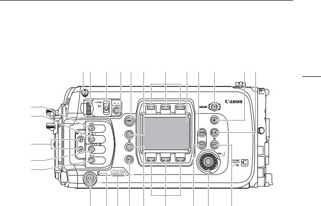
Names of Parts
Names of Parts |
|
|
|
|
|
|
|
|
6 7 |
8 |
9* 10* 11* |
12* |
13 |
14* |
15* |
16*17* |
13 |
1* |
|
|
|
|
|
|
|
|
2* |
|
|
|
|
|
|
|
|
3* |
|
|
|
|
|
|
|
|
4* |
|
|
|
|
|
|
|
|
5* |
|
|
|
|
|
|
|
|
18* 19 20 21* 22* |
12* |
23* 24 |
25* |
* Illuminated buttons (A197).
1MAGN. (magnification) button (A92)/ Assignable button Camera 1 (A127)
2PEAKING button (A91)/
Assignable button Camera 2 (A127)
3 ND FILTER +/– buttons (A78)
4FALSE COLOR button (A100)/ Assignable button Camera 3 (A127)
5WFM (waveform monitor) button (A115)/
Assignable button Camera 4 (A127)
6 Tape measure hook and  focal plane mark
7Control dial (A77, 80)
8CUSTOM (customize the control dial’s function)
switch (A77)
9PUSH AUTO IRIS (momentary automatic aperture)
button (A81)
10USER (user-defined setup screen) button (A130)
11ALT (alternative setup screen) button (A186)
12Screen buttons (A30)
13Control display (A30)
14HOME (home setup screen) button (A30, 185)
15Qbutton (A28)
16C(key lock) button (A56)
17MENU (camera menu) button (A32)
18REC (start/stop recording) button (A55)
19Tally lamp (A55)
20Speaker (A56)
21PLAY (playback mode) button (A141)
22TC (time code) button (A101, 187)
23BACK (go back to previous screen) button (A30, 32)
24SELECT dial/SET button (A30, 32)
25INFO (information screens) button (A201)
Names of Parts
p15 |
|
|
|
|
|
|
|
|
1 |
2 |
3 |
4 |
5 |
6 |
7 |
8 |
9 10 |
14
11 |
12 13 14 |
15 |
16 |
17 |
18 |
19 |
20 |
21 |
1 |
D-TAP terminal (A28) |
13 |
SD card slot cover switch (A50) |
|
|
||||
2 |
Cable clamp |
14 |
SD CARD access indicator (A50) |
|
|
||||
3 |
Exhaust ventilation outlet (A64) |
15 |
CFast |
(CFast card slot A) and CFast |
(CFast |
||||
4 |
Tally lamp (A55) |
|
card slot B) access indicators (A49) |
|
|||||
5 |
System extension terminal (A120, 162) |
16 |
CFast card slot cover switches: for CFast |
(top), |
|||||
6 |
REC (start/stop recording) button (A55) |
|
for CFast |
(bottom) (A49) |
|
|
|
||
7 |
SLOT SEL. (CFast card selection) button |
17 |
SD card slot cover (A50) |
|
|
|
|||
|
(A52, 142) |
18 |
SD card slot (A50) |
|
|
|
|||
8 |
Serial number |
19 |
CFast card slot covers: for CFast |
(top), for |
|||||
9 |
Air intake vent (A64) |
|
CFast |
(bottom) |
|
|
|
||
10 |
Tape measure hook and |
|
focal plane mark |
20 |
CFast card slots: for CFast |
(top), for CFast |
|||
|
|||||||||
11 |
Audio input selection switches: for INPUT 1 (top), |
|
(bottom) (A49) |
|
|
|
|||
|
for INPUT 2 (bottom) (A108, 110) |
21 |
CFast card release switches: for CFast |
(top), |
|||||
12 |
ANALOG (analog audio source selection) |
|
for CFast |
(bottom) (A49) |
|
|
|
||
|
switches: for INPUT 1 (top), for INPUT 2 (bottom) |
|
|
|
|
|
|
||
|
(A108, 110) |
|
|
|
|
|
|
||

Names of Parts
7 8 |
9 |
10 |
14 |
15 |
10 |
15 |
|||
|
|
|
|
|
|
|
|
|
|
|
|
|
|
|
|
|
|
|
|
1
2
3
4
5
6
11 |
12 |
13 |
ZEF lens mount with Cinema Lock (A44)
11 |
16 |
17 |
13 |
[]PL lens mount (A46)
1 |
MIC (microphone) terminal (A109) |
8 |
EF lens mount index (A44) |
2 |
VIDEO terminal (A41) |
9 |
Lens mount handles |
|
For connecting the optional EVF-V70 OLED |
10 |
Built-in monaural microphone (A110) |
|
Electronic Viewfinder. |
11 |
REC (start/stop recording) button (A55) |
3 |
DC OUT 24V 2A (power output) terminal (A28) |
12 |
EF lens contacts (A44) |
4 |
DC OUT 12V 2A (power output) terminal (A28) |
13 |
ONE-SHOT AF (focus automatically once) button |
5 |
CTRL (controller) terminal (A38) |
|
(A92)/Assignable button Camera 5 (A127) |
|
For connecting the optional OU-700 Remote |
14 |
Bayonet ring handles |
|
Operation Unit. |
15 |
PL lens index pin (A46) |
6 |
LENS terminal (A44) |
16 |
PL lens contacts (A46) |
7 |
EF-S lens mount index (A44) |
17 |
Bayonet ring |
Removing and Attaching the Terminal Covers
You can remove the covers of the camera’s terminals to access them more easily. The terminal cover of the terminals below the MIC terminal (on the camera’s front side) is common to all 6 terminals. Terminal covers for other terminals can be removed by removing the small screw using a Phillips head (“crosshead”) screwdriver. Be careful not to lose the terminal covers or fixation screws once removed.
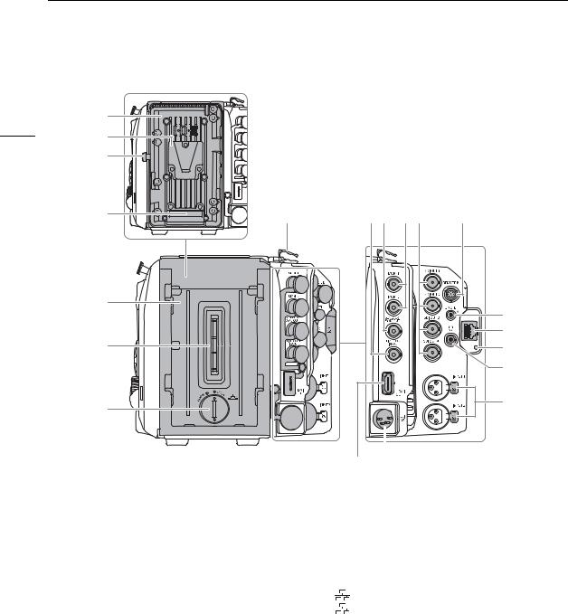
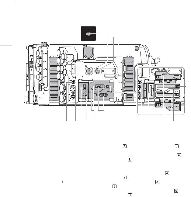
Names of Parts
|
|
(with the supplied battery adapter attached to the camera) |
|
|
|
16 |
1 |
MON. 1 |
|
|
|
2 |
|
|
|
|
|
|
|
|
|
|
|
|
3 |
|
|
|
|
|
4 |
8 |
9 10 |
1112 |
13 |
5 |
14 |
|
|
6 |
15 |
16 |
|
|
17 |
7 |
18 |
|
|
(with no extension module attached to the camera) |
|
|
|
|
|
19 |
20 |
|||
|
|
|
|||
1 |
V-mount battery plate (A26) |
12 |
SDI OUT terminals: from top to bottom SDI OUT 1 |
||
2 |
V-shaped battery mount (V-mount) |
|
to SDI OUT 4 (A149, 152) |
||
3 |
Battery release latch (A26) |
13 |
REMOTE B terminal |
||
4 |
Battery contacts |
14 |
REMOTE A terminal |
||
5 |
Extension module mounting unit (A23, 24) |
|
For connecting the optional RC-V100 Remote |
||
6 |
Extension module connector |
|
Controller (A123) or commercially available |
||
7 |
Compartment cover for the lithium button battery |
|
remote controllers. |
||
|
(A24) |
15 |
(Ethernet) terminal (A166) |
||
8 |
Cable clamp |
16 |
(Ethernet) indicator |
||
9 |
TIME CODE IN/OUT terminal (A105, 106, 107) |
17 |
×(headphone) terminal (A113, 143) |
||
10 |
GENLOCK terminal (A105, 106)/ |
18 |
INPUT terminals (XLR): INPUT 1 (top), INPUT 2 |
||
|
SYNC OUT (synchronizing signal output) terminal |
|
(bottom) (A109, 110) |
||
|
(A105, 107) |
19 |
HDMI OUT terminal (A149, 153) |
||
11 |
MON. terminals: MON. 1 (top), MON. 2 (bottom) |
20 |
DC IN 12V terminal (A27) |
||
|
(A149, 153) |
|
|
|
|

Names of Parts
1 |
2 |
3 |
4 |
5 |
6 |
7 |
8 |
|
|
|
17 |
|
2 |
3 |
|
9 |
7 |
1 |
Tape measure hooks and |
focal plane marks |
5 |
Socket for the extension unit attachment bracket |
|
|
Use the hooks to accurately measure the distance |
|
(A120, 162) |
|
|
|
from the focal plane. |
|
6 |
Battery adapter release switch (A23, 24) |
|
2 |
Screw holes for 1/4"-20 mounting screws (10 mm |
7 |
Battery adapter’s fixation screws (2 on the top |
||
|
(0.39 in.) deep) |
|
|
plate, 2 on the bottom plate; M4) (A23, 24) |
|
|
Total of 36 on the top plate and 16 on the bottom |
8 |
Battery adapter for V-mount batteries |
||
|
plate. |
|
|
(A23, 24, 26) |
|
3 |
Screw holes for 3/8"-16 mounting screws |
9 |
Rubber anti-slip feet |
|
|
|
(12 mm (0.47 in.) deep) |
|
|
The screw holes on the bottom can be used to |
|
|
Total of 10 on the top plate and 5 on the bottom |
|
attach the supplied rubber anti-slip feet as shown |
||
|
plate. |
|
|
in the illustration. |
|
4Screw holes for 1/4"-20 mounting screws (10 mm (0.39 in.) deep)
Recommended mounting position for the optional OU-700 Remote Operation Unit.
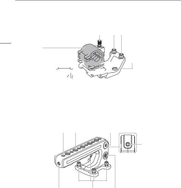
Names of Parts
Microphone Holder (A109)
1 |
|
|
|
4 |
|
|
18
2


 5 3
5 3 


1 |
Microphone lock screw |
4 |
Hex socket head fixation bolts (0.64 cm, |
2 |
Microphone holder |
|
1/4"; 2 in total) |
3 |
Microphone cable clamp |
5 |
Through-holes for fixation bolts |
Handle Unit (A40)
1 |
2 |
1* |
2
1 |
3 |
2* |
* One more in the same location on the opposite side.
1 |
Screw holes for 1/4"-20 mounting screws |
3 Hex socket head fixation bolts |
|
(10 mm (0.39 in.) deep, 9 in total) |
(0.64 cm, 1/4"; 4 in total) |
2 |
Screw holes for 3/8"-16 mounting screws |
|
|
(12 mm (0.47 in.) deep, 8 in total) |
|

Names of Parts
Clamp Base (A41)
1 |
2 |
3 |
19
1 |
Slider for an optional viewfinder’s clamp rail |
3 Hex socket head fixation bolts (0.64 cm, 1/4"; |
2 |
Clamp rail locking screw |
4 in total) |

Names of Parts
EVF-V70 OLED Electronic Viewfinder (optional) (A41)
1* |
2* 3* |
4 5 6 |
7 |
8* |
9* 10 11 |
20
|
|
|
|
|
|
|
|
|
|
|
|
|
|
|
|
|
|
|
|
|
|
|
|
|
|
|
|
|
|
|
|
|
|
|
|
|
|
|
|
|
|
|
|
|
|
|
|
|
|
|
|
|
|
|
|
|
|
|
|
|
|
|
|
|
|
|
|
|
|
|
|
|
|
|
|
|
|
|
|
|
|
|
|
|
|
|
|
|
|
|
|
|
|
|
|
|
|
|
|
|
|
|
|
|
|
|
|
|
|
|
|
|
|
|
|
|
|
|
|
|
|
|
|
|
|
|
|
|
|
|
|
|
|
12 |
|
|
|
|
10 |
13 14 |
15 |
|
16 |
* Illuminated buttons (A197). |
|||||||
1 |
FUNC (main functions) button (A73)/ |
|
|
9 |
FALSE COLOR button (A100)/ |
|||||||||||||
|
Assignable button EVF 1 (A127) |
|
|
|
Assignable button EVF 4 (A127) |
|||||||||||||
2 |
EVF (open the monitoring menu) button (A33, |
10 |
Swing arm locking screw (A41) |
|||||||||||||||
|
188)/Assignable button EVF 2 (A127) |
|
|
11 |
Swing arm |
|
||||||||||||
3 |
BACK (go back to previous screen) button |
|
|
12 |
VIDEO terminal (A42) |
|||||||||||||
|
(A30, 32) |
|
|
|
|
|
|
|
|
13 |
Screw hole for 1/4"-20 mounting screws |
|||||||
4 |
Viewfinder (A41) |
|
|
|
|
|
|
|
|
|
(25 mm (0.98 in.) deep) |
|||||||
5 |
Eye sensor (A42) |
|
|
|
|
|
|
|
|
14 |
SELECT dial/SET button (A32) |
|||||||
6 |
Eyecup |
|
|
|
|
|
|
|
|
15 |
Joystick (A32)/SET button (A32) |
|||||||
7 |
Dioptric adjustment ring (A42) |
|
|
16 |
Swing arm slider (A41) |
|||||||||||||
8MAGN. (magnification) button (A92)/ Assignable button EVF 3 (A127)
|
17 |
18 |
|
||
|
|
|
|
|
|
|
|
|
|
|
|
|
|
|
|
|
|
|
|
|
|
|
|
|
|
|
|
|
|
|
|
|
|
|
|
|
|
|
|
|
|
|
|
|
|
|
|
|
|
|
|
|
|
|
|
|
|
|
|
|
|
|
|
|
|
|
|
|
|
|
|
19 |
20 |
17 |
Clamp rail: cable clamps |
19 |
Clamp rail: rail end caps (A41) |
18 |
Screw holes for the clamp rail’s cable clamps |
20 |
Clamp rail: slider locking pin (A43) |
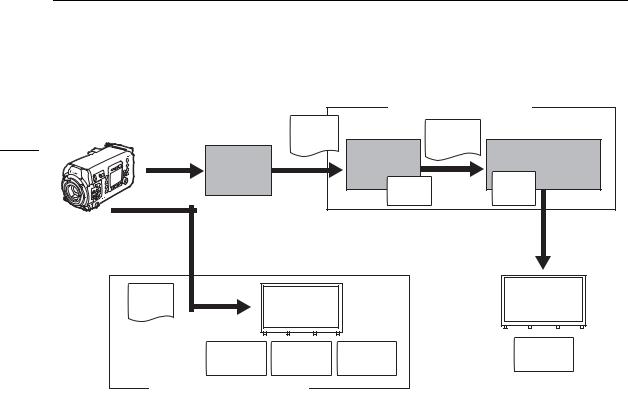
4K Workflow Overview
4K Workflow Overview |
|
|
|
|
|
The following illustrates the typical 4K workflow for this camera. |
|
|
|
||
Recording |
|
|
|
Post-production |
21 |
|
|
|
|
NLE Software |
|
|
|
|
RAW |
|
|
|
CDX-36150 |
RAW data |
|
Plugin |
|
Extension module |
Recorder |
|
|
||
|
|
Cinema |
|
||
|
|
|
|
||
connector (docking) |
4K recording |
|
|
|
|
|
|
RAW |
|
||
|
(RAW) |
|
Development |
|
|
|
|
|
Full-quality |
|
|
|
|
data |
|
||
|
CDX-36150 |
|
|
||
|
|
|
|
|
|
Extension module |
Recorder |
YCbCr |
|
|
Color |
|
|
|
|||
connector (docking) |
4K or 2K recording |
|
|
||
4:2:2 data |
|
|
grading |
||
|
(ProRes) |
|
|
|
|
|
|
Proxy |
|
|
|
|
CFast card |
|
|
|
|
Internal recording |
|
data |
|
|
|
|
|
|
|
|
|
4K or 2K recording |
|
EDL |
|
||
|
|
|
|||
|
(XF-AVC/ProRes) |
|
|
|
|
SD card |
Proxy data |
NLE software |
|
Internal recording
2K recording (XF-AVC Proxy)
Shoot in 4K mode (A65).
You can record RAW data on a CDX-36150 Recorder docked with the camera*. You can also record Intra-frame (YCbCr 4:2:2) 4K data on a CDX-36150 Recorder or on a CFast card in the camera.
In addition to the main RAW recording, you can record simultaneously an additional sub recording in the camera (A71). You can use the CFast card (XF-AVC clips, 4K or 2K) or SD card (XF-AVC Proxy clips, 2K), depending on the type of sub recording clips you need or how you intend to use them in post-production.
After recording RAW data, you can develop the RAW data using the Cinema RAW Development software (A160) to generate full-quality data. Using the Canon RAW Plugin, you can work with RAW recordings directly from supported NLE applications.
•You can also generate proxy data with the software.
•YCbCr 4:2:2 clips recorded on the CFast card can be treated as full-quality data without any additional processing.
Transfer the 2K clips recorded in the camera or CDX-36150 Recorder, or proxy data generated by the software, to your NLE system and edit offline (A160).
Perform color grading based on the full-quality data.
*For details about docking the CDX-36150 Recorder with the camera and using it to record, refer to Codex Recorder – Guide for the EOS C700 models (separate PDF file).
4K Workflow Overview
|
Color Grading with the ACES Workflow |
|
|
|
|
Extension |
|
Post-production |
|
22 |
module |
RAW |
OpenEXR |
|
connector |
|
|||
data |
(ACES 1.0) |
|
||
|
(docking) |
|
Cinema RAW |
Color grading |
|
CDX-36150 |
|
Development |
|
|
|
|
||
|
Recorder |
|
Input |
ASC- |
|
|
|
||
|
|
|
CDL |
|
|
4K recording |
|
Transform |
|
|
|
|
|
|
|
(RAW) |
|
|
|
|
MON. or HDMI OUT |
|
|
|
|
output |
|
|
|
|
ACES |
|
|
|
|
proxy |
|
|
|
|
Inverse log |
|
Output |
Output |
|
ASC-CDL |
Transform |
||
|
Transform |
|||
|
|
|
|
|
|
On-set Color Grading |
|
|
|
ACESproxy: |
ACESproxy video data that is output from the MON. terminals or HDMI OUT terminal when |
|
performing on-set color grading. Select the [ACESproxy] option for the LUT setting of the |
|
appropriate terminal (A154) to enable ACESproxy output. |
Input Transform: |
Refers to the table used for converting color information of the input device to ACES2065-1 |
|
color space. |
Output Transform: Refers to the table used for mapping ACES2065-1 color space information to the specific
|
color information scheme used by the display device. |
ASC-CDL: |
Refers to the list that contains color grading adjustment data. This step requires equipment |
|
compatible with ASC-CDL. |
2 |
Preparations |
|
23
Preparing the Backup Battery
The camera uses a CR2025 lithium button battery as a backup battery to ensure that the camera’s settings are not lost when no other power source is connected to the camera. To install the supplied lithium button battery, you will need to remove any extension modules attached to the camera*.
* The camera is shipped with the battery adapter for V-mount batteries attached.
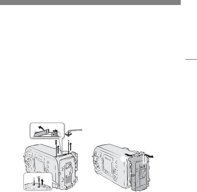
Removing an Extension Module
The following procedure is explained using the battery adapter for V-mount batteries supplied with the camera as example.


1 Use the supplied hex wrench to remove the four fixation screws from the top and bottom of the battery adapter.
2 Slide the battery adapter release switch in the direction of the arrow.
• The locking lever will pop out.
3 Pull the locking lever all the way up and pull the top of the battery adapter away from the camera. 4 Lift up the battery adapter and remove it from the camera.
5 Push down the locking lever until it clicks.
Preparing the Backup Battery
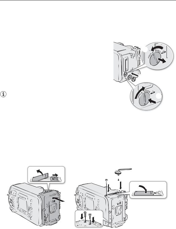
Inserting the Lithium Button Battery
The camera features a built-in backup battery so the camera settings are not lost while you replace the lithium button battery.
24 1 |
Make sure no power supply is connected to the DC IN 12V |
|
||
|
|
terminal. |
|
|
|
|
|||
2 |
Turn the lithium battery compartment cover to the OPEN |
|||
|
||||
|
|
position and remove the cover. |
|
|
|
|
• Use a coin or a similar tool. If you keep turning the cover beyond |
|
|
|
|
the OPEN point, the cover will rise a little, making it easier to grab. |
|
|
3 |
Insert the supplied lithium button battery with the + side |
|
||
|
|
facing out. |
||
|
|
|
||
4 Replace the cover and turn it to the LOCK position to lock it.
NOTES |
|
|
• The built-in backup battery will be completely depleted if you do not use the camera for about 1 month. Replacing the lithium button battery in such case will reset all the camera’s settings to default values. To avoid losing the settings, you can save them on an SD card in advance (A140).
•To recharge the built-in backup battery, turn off the camera and connect a sufficiently charged power source (battery or DC IN 12V terminal). The built-in backup battery will be fully charged in about 24 hours.
Installing an Extension Module
The following procedure is explained using the battery adapter for V-mount batteries supplied with the camera as example.


1 Slide the battery adapter release switch in the direction of the arrow.
• The locking lever will pop out. Once it does, pull the locking lever all the way up.
2 Attach the battery adapter to the camera and slide it down.
• Align the positioning protrusions on the battery adapter with the holes on the camera’s body.
3 Gently press the battery adapter toward the camera.

Preparing the Backup Battery
4 Push down the locking lever until it clicks.
5 Using the supplied hex wrench, attach the four fixation screws to the top and bottom of the battery adapter to secure it in place.
25

Preparing the Main Power Supply
Preparing the Main Power Supply
You can power the camera using a commercially available V-mount battery or the DC IN 12V terminal. Even when a battery is attached, if a power source is connected to the DC IN 12V terminal, the camera will not draw
26 power from the battery.
Acceptable Power Sources
When selecting commercially available batteries and power adapters, make sure the external power source meets the following specifications and all the safety standards of the country/region where it is used. Closely follow the manufacturer’s instructions regarding the use and maintenance of power sources.
Power source |
Specifications |
Battery |
V-mount battery, 14.8 V DC (acceptable range: 12 V to 20 V DC) |
|
|
Power adapter |
4-pin XLR plug (female connector), 12 V DC (acceptable range: 11.5 V to 20 V DC), 10 A (acceptable maximum |
(DC IN 12V terminal) |
load current) |
|
|
Using a Battery
The battery adapter for V-mount batteries comes attached to the camera. If it was removed, attach the battery adapter in advance (A24).
Attaching a Battery
1 Make sure the camera is turned off.
2Align the V-shaped wedge on the battery to the V-mount on the battery plate.
3 Gently press the battery down until it clicks in place.
Removing a Battery
1 Press the Qbutton to turn off the camera.
2While holding the battery release latch pressed down, slide the battery up and remove it.


Using the DC IN 12V Terminal
1 Press the Qbutton to turn off the camera.
2Connect the 4-pin XLR connector of the external power supply to the camera’s DC IN 12V terminal.
 IMPORTANT
•Make sure to turn off the camera before connecting or disconnecting an external power source to/from the camera’s DC IN 12V terminal.
Preparing the Main Power Supply
27


Checking the Camera’s Power Levels
You can check the voltage level of the power source used on the camera’s HOME screen and on the shooting screen that appears on monitoring devices (A57, 59).
You can use the 

 [System Setup] >[Low Power Warning] settings to set a critical power level independently for the DC IN 12V terminal and battery. When the power input to the camera reaches the predetermined level, the onscreen power indicator will change to red and a message will appear in the


[LIVE] screen. When using a battery compatible with BMS (battery management system), you can even set the warning level as a percentage of the remaining battery charge instead of voltage.
Preparing the Main Power Supply
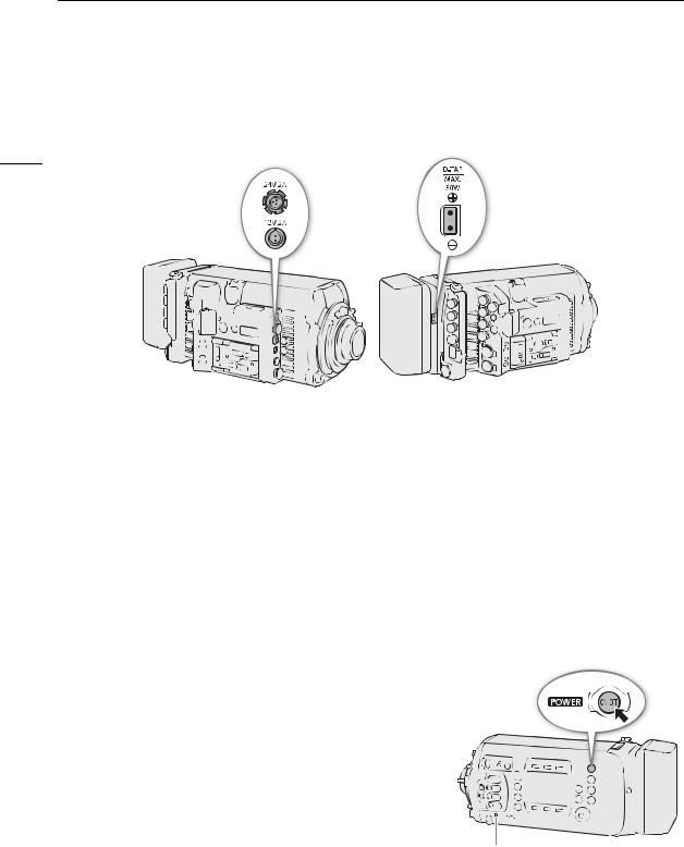
Power Outputs
The camera features three power outputs for accessories: the DC OUT 24V 2A terminal, the DC OUT 12V 2A terminal and the D-TAP terminal on the battery adapter.
28
Power output |
Specifications* |
DC OUT 24V 2A terminal |
Fischer 3-pin connector, 24 V DC, 2.0 A (max.) |
|
|
DC OUT 12V 2A terminal |
LEMO 2-pin connector, 12 V DC, 2.0 A (max.) |
|
|
D-TAP terminal |
D-Tap connector, 50 W (max.) |
|
|
* Actual levels may vary depending on the power source supplying the camera.
 IMPORTANT
•Be sure to use the camera’s power outputs within the specifications given.
•When supplying power to external accessories, be careful of the polarity of the power connections. Connecting the power supply incorrectly can cause malfunctions.
Turning the Camera On and Off
After connecting an appropriate power source to the camera, press the Qbutton to turn on the camera. While the camera is starting up, the tally lamp will illuminate in red. When the camera is ready to start recording, the tally lamp will change to green and the HOME screen will be displayed on the camera’s control display.
To turn off the camera, press and hold the Qbutton. After the countdown that appears on the control display ends, the camera will start the shutting down process and will turn off after a few seconds.
Tally lamp
Date, Time and Language Settings
Date, Time and Language Settings |
|
|
|
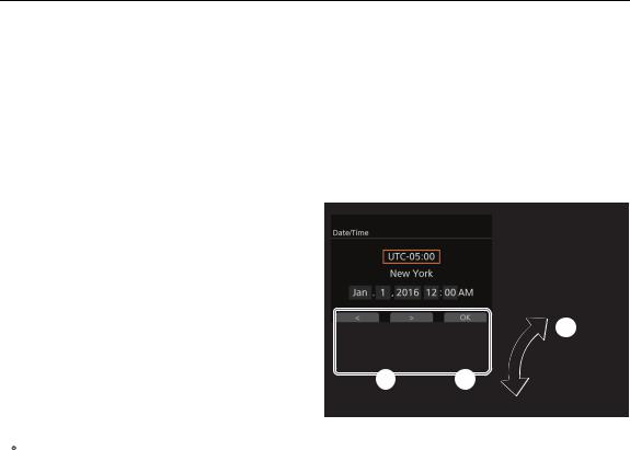
Setting the Date and Time |
|
|
|
You will need to set the date and time on the camera before you can start using it. When you turn on the camera |
29 |
||
for the first time or after the camera’s settings were reset, the [Date/Time] screen will appear automatically on the |
|||
|
|||
control display with the time zone selected so you can set the camera’s internal clock. |
|
||
1 Turn the SELECT dial to select the desired time |
|
|
|
zone and then press SET to move to the next |
|
|
|
field. |
|
|
|
• The default time zone is [UTC-05:00] (New York) |
|
|
|
or [UTC+01:00] (Central Europe), depending on |
|
|
|
the country/region of purchase. Time zones are |
|
|
|
based on Coordinated Universal Time (UTC). |
|
|
|
2 Change the rest of the fields in the same way. |
|
|
|
• You can also press the [<] and [>] screen buttons |
|
|
|
to move between the various fields. |
|
|
|
|
|
|
|
3 After correctly setting the date and time, press the [OK] screen button to start the clock and close the screen.
 NOTES
NOTES
•With the 

 [System Setup] >[Set Clock] settings, you can change the time zone, date and time also after the initial setup. You can also change the date format.
•If the lithium button battery and built-in backup battery are both completely depleted, all menu settings will be lost. In such case, replace the lithium button battery (A23) and perform the initial setup again.
•Using the optional GP-E1 GPS Receiver, you can have the camera adjust settings automatically according to the UTC date/time information received from the GPS signal (A120).
Changing the Language
The camera’s default language is English. You can change it to German, Spanish, French, Italian, Polish, Portuguese, Russian, Simplified Chinese, Korean or Japanese. Please note that some settings and screens will be displayed in English, regardless of the language setting.
1 Press the MENU button.
2 Turn the SELECT dial to select [System Setup] and then press SET. 3 Select [Language H] in a similar fashion and then press SET.
4 Turn the SELECT dial to select a language.
5 Press SET to change the language and then press the HOME button to close the menu.
Changing Camera Settings with the Screen Buttons
Changing Camera Settings with the Screen Buttons
There are three basic ways to change the various camera settings: Using the screens that appear on the camera’s control display and the screen buttons, using the camera menu displayed on the control display, and
30using the monitoring menu displayed on monitoring devices along with the camera’s image. The menus will be explained in the following section (A32). This section will explain the use of the control display screens and screen buttons. When an optional OU-700 Remote Operation Unit is connected to the camera, using the OU-700 is identical to using the camera’s control display and buttons.
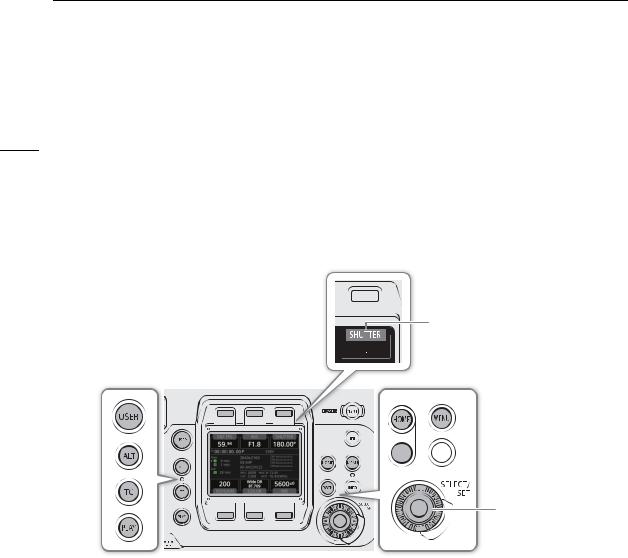
Unlike the menus, the function of the screen buttons changes dynamically depending on the button pressed on the camera and the screen currently displayed on the control display. The current function of the screen buttons is displayed in the gray area immediately above/below the screen button. If applicable, the current setting is displayed within the white enclosure connected to it.
Screen button. In this example, pressing the button will open a screen where you can change the shutter speed.
Current value of the shutter speed. 


Current function of the screen button. In the manual pressing this screen button will be referred to as “Press [SHUTTER]”.


 BACK button: Return to the previous screen without changing the setting.
SELECT dial: Turn to move between options.
SET button: Confirm the selected option.
The HOME, USER, ALT, TC and PLAY buttons, each opens a different setup screen where you can change settings or perform actions (A185).
Options
HOME screen: This screen is displayed by default when you turn on the camera. In this screen you can change the frame rate, aperture and ND filter settings, shutter speed, ISO speed/gain, custom picture settings and white balance. You can also check the status of the camera, clip name, recording format, information about recording media and power supply.
USER screen: You can customize this screen to your needs by assigning the functions you prefer to the 6
|
screen buttons. |
ALT screen: |
In this screen you can change settings related to autofocus (Zonly) and the focus |
|
assistance functions, audio, the camera’s electronic level and network functions. |
TC screen: |
In this screen you can change time code related settings. |
PLAY screen: |
In this screen you can control the playback of your recordings (playback mode). |
Loading...