


 Loading...
VIDEOJET decoder 3000
VJD-3000
en Installation Manual

VIDEOJET decoder 3000 Table of Contents | en 3
Table of contents
1 |
Safety |
5 |
1.1 |
Electric shock hazard |
5 |
1.2 |
Installation and operation |
5 |
1.3 |
Maintenance and repair |
6 |
2 |
Short information |
7 |
2.1 |
About this manual |
7 |
2.2 |
Conventions in this manual |
7 |
2.3 |
Intended use |
7 |
2.4 |
EU Directives |
7 |
2.5 |
Rating plate |
7 |
3 |
System overview |
8 |
3.1 |
Parts included |
8 |
3.2 |
System requirements |
8 |
3.3 |
Overview of functions |
8 |
3.4 |
Connections, controls and displays |
10 |
3.4.1 |
Front view |
10 |
3.4.2 |
Rear view |
11 |
4 |
Installation |
12 |
4.1 |
Preparations |
12 |
4.2 |
Mounting |
12 |
4.3 |
Installing in a switch cabinet |
13 |
5 |
Connection |
15 |
5.1 |
Connecting monitors |
15 |
5.2 |
Connecting audio |
16 |
5.3 |
Establishing the network connection |
17 |
5.4 |
Connecting alarm inputs and relay output |
17 |
5.5 |
Creating a serial connection |
18 |
5.6 |
Connecting the power supply |
19 |
6 |
Configuration |
21 |
6.1 |
Setup |
21 |
6.2 |
Setup using Bosch Video Client |
21 |
7 |
|
|
Troubleshooting |
23 |
|
7.1 |
Contact |
23 |
7.2 |
General malfunctions |
23 |
7.3 |
LEDs |
24 |
7.4 |
Processor load |
25 |
7.5 |
Network connections |
25 |
7.6 |
Terminal block |
25 |
7.7 |
Copyrights |
26 |
8 |
|
|
Maintenance |
27 |
|
8.1 |
Updates |
27 |
8.2 |
Factory reset |
27 |
8.3 |
Repairs |
27 |
9 |
|
|
Decommissioning |
28 |
|
9.1 |
Transfer |
28 |
9.2 |
Disposal |
28 |
Bosch Sicherheitssysteme GmbH |
Installation Manual |
2014.01 | V4 | F.01U.296.741 |

4 en | Table of Contents VIDEOJET decoder 3000
10 |
Technical data |
29 |
10.1 |
Electrical |
29 |
10.2 |
Mechanical |
29 |
10.3 |
Environmental conditions |
29 |
10.4 |
Standards |
30 |
|
|
|
|
Index |
31 |
2014.01 | V4 | F.01U.296.741 |
Installation Manual |
Bosch Sicherheitssysteme GmbH |

VIDEOJET decoder 3000 Safety | en 5
1 |
Safety |
1.1 |
Electric shock hazard |
|
– Never attempt to connect the unit to any power network other than the type for which it |
|
is intended. |
|
– Use only the power supply provided or power supply units with UL approval and a power |
|
output according to LPS or NEC Class 2. |
|
– Connect the unit to an earthed mains socket-outlet. |
|
– Never open the housing. |
|
– Never open the housing of the power supply unit. |
|
– If a fault occurs, disconnect the power supply unit from the power supply and from all |
|
other units. |
|
– Install the power supply and the unit only in a dry, weather-protected location. |
|
– When installing in a switch cabinet, ensure that the unit and the power supply units have |
|
sufficient grounding. |
|
– If safe operation of the unit cannot be ensured, remove it from service and secure it to |
|
prevent unauthorized operation. In such cases, have the unit checked by Bosch Security |
|
Systems. |
|
Safe operation is no longer possible in the following cases: |
|
– if there is visible damage to the unit or power cables, |
|
– if the unit no longer operates correctly, |
|
– if the unit has been exposed to rain or moisture, |
|
– if foreign bodies have penetrated the unit, |
|
– after long storage under adverse conditions, or |
|
– after exposure to extreme stress in transit. |
1.2 |
Installation and operation |
–The relevant electrical engineering regulations and guidelines must be complied with at all times during installation.
–Relevant knowledge of network technology is required to install the unit.
–Before installing or operating the unit, make sure you have read and understood the documentation for the other equipment connected to it, such as monitors. The documentation contains important safety instructions and information about permitted uses.
–Perform only the installation and operation steps described in this manual. Any other actions may lead to personal injury, damage to property or damage to the equipment.
Please ensure the following installation conditions:
–Do not install the unit or the power supply unit close to heaters or other heat sources. Avoid locations exposed to direct sunlight.
–Allow sufficient space for running cables.
–Ensure that both the unit and the power supply unit have adequate ventilation. Bear the total heat output in mind, particularly when installing multiple units in a switch cabinet.
–When making connections, use only the cables supplied or use appropriate cables immune to electromagnetic interference.
–Position and run all cables so that they are protected from damage, and provide adequate cable strain relief where needed.
–When installing in a switch cabinet, ensure that the screw joints are free of tension and subject to as little mechanical stress as possible. Ensure that the unit and the power supply unit have sufficient grounding.
Bosch Sicherheitssysteme GmbH |
Installation Manual |
2014.01 | V4 | F.01U.296.741 |

6 en | Safety VIDEOJET decoder 3000
|
– Avoid impacts, blows, and severe vibrations that exceed the specification limits, as these |
|
can irreparably damage the unit. |
1.3 |
Maintenance and repair |
– Never open the housing of the unit. The unit does not contain any user-serviceable parts.
– Never open the housing of the power supply unit. The power supply unit does not contain any user-serviceable parts.
– Ensure that all maintenance or repair work is carried out only by qualified personnel (electrical engineers or network technology specialists). In case of doubt, contact your dealer's technical service center.
2014.01 | V4 | F.01U.296.741 |
Installation Manual |
Bosch Sicherheitssysteme GmbH |

VIDEOJET decoder 3000 Short information | en 7
2 |
Short information |
2.1 |
About this manual |
|
This manual is intended for persons responsible for the installation and operation of a |
|
VIDEOJET decoder 3000 unit. International, national and any regional electrical engineering |
|
regulations must be followed at all times. Relevant knowledge of network technology is |
|
required. The manual describes the installation of the unit. |
2.2 |
Conventions in this manual |
In this manual, the following symbols and notations are used to draw attention to special situations:
Caution!
This symbol indicates that failure to follow the safety instructions described may endanger
!persons and cause damage to the unit or other equipment. It is associated with immediate, direct hazards.
Notice!
This symbol refers to features and indicates tips and information for easier, more convenient use of the unit.
2.3 |
Intended use |
|
VIDEOJET decoder 3000 receives and decodes video signals over data networks (Ethernet |
|
LAN, Internet). The unit is intended for use with CCTV systems. Various functions can be |
|
triggered automatically by incorporating external alarm sensors. Other applications are not |
|
permitted. |
|
In the event of questions concerning the use of the unit which are not answered in this |
|
manual, please contact your sales partner or: |
|
Bosch Sicherheitssysteme GmbH |
|
Robert-Bosch-Ring 5 |
|
85630 Grasbrunn |
|
Germany |
|
www.boschsecurity.com |
2.4 |
EU Directives |
|
VIDEOJET decoder 3000 complies with the requirements of EU Directives 89/336 |
|
(Electromagnetic Compatibility) and 73/23, amended by 93/68 (Low Voltage Directive). |
2.5 |
Rating plate |
For exact identification, the model name and serial number are inscribed on the bottom of the housing. Please make a note of this information before installation, if necessary, so as to have it to hand in case of questions or when ordering spare parts.
Bosch Sicherheitssysteme GmbH |
Installation Manual |
2014.01 | V4 | F.01U.296.741 |

8 en | System overview VIDEOJET decoder 3000
3 |
System overview |
|
3.1 |
Parts included |
|
|
– 1 VIDEOJET decoder 3000 video decoder |
|
|
– 2 terminal blocks (6-pin, 8-pin) |
|
|
– 4 self-adhesive elastic bumpers |
|
|
– 1 wall-mounting panel |
|
|
– |
2 screws |
|
– |
2 wall plugs |
|
– 1 power supply unit with 3 primary adapters (EU, US, UK) |
|
|
– |
1 Installation Manual |
|
|
|
|
Notice! |
|
|
Check that the delivery is complete and in perfect condition. Arrange for the unit to be |
|
|
checked by Bosch Security Systems if you find any damage. |
|
|
|
|
3.2 |
System requirements |
|
|
General requirements |
|
|
– Computer with Windows XP or Windows 7 operating system |
|
|
– Network access (Intranet or Internet) |
|
|
– Screen resolution at least 1,024 × 768 pixels |
|
|
– 16or 32-bit color depth |
|
|
– |
Installed Oracle JVM |
|
|
|
|
Notice! |
|
|
The Web browser must be configured to enable cookies to be set from the IP address of the |
|
|
unit. |
|
|
In Windows 7, deactivate protected mode on the Security tab under Internet Options. |
|
|
You can find notes on using Microsoft Internet Explorer in the online Help in Internet |
|
|
Explorer. |
|
|
|
|
|
Additional configuration and operational requirements |
|
|
You find the information on additional configuration and operational requirements in the |
|
|
Releaseletter document for the respective firmware. |
|
|
For the latest version of the firmware, required programs and controls, and the current version |
|
|
of the Bosch Video Client management software, access your Bosch product catalog on the |
|
|
Internet. |
|
3.3 |
Overview of functions |
|
|
High Definition video decoder |
|
|
VIDEOJET decoder 3000 displays H.264 encoded video at up to 60 images per second from |
|
|
PAL, NTSC, or HD sources over IP networks. |
|
Establish the video connections automatically from the camera, encoder, decoder, or the comprehensive video management system from Bosch. The decoder is capable of decoding a single HD video stream, or up to four SD video streams at the same time in quad-mode. Control the viewing mode remotely via a management system. It can drive an HD monitor via HDMI directly, thus is ideally suited for applications like flat-screen monitor walls. Alternatively, it can connect to an analogue monitor using its composite video BNC output.
2014.01 | V4 | F.01U.296.741 |
Installation Manual |
Bosch Sicherheitssysteme GmbH |

VIDEOJET decoder 3000 |
System overview | en |
9 |
|
|
|
VIDEOJET decoder 3000 provides one-channel bidirectional audio communication in parallel to video.
Ultra-compact in size, VIDEOJET decoder 3000 is perfect for any application that depends on space-saving solutions.
Access security
VIDEOJET decoder 3000 offers various security levels for accessing the network, the unit, and the data channels. As well as password protection with two levels, it supports 802.1x authentication using a RADIUS server for identification. You can secure Web browser access by HTTPS using a SSL certificate that is stored in the unit, providing total data protection with AES or 3DES encryption, according to the client's encryption capabilities. Alternatively, each communication channel—video, audio, or serial I/O—can be independently AES encrypted with 128 bit keys, once the encryption site license has been applied.
High performance
Transmit IP video to the high-performance decoder and present it with ultimate clarity on an analog CCTV monitor or on a large, flat-screen display.
VIDEOJET decoder 3000 can handle up to four SD H.264 video streams with full resolution and frame rate and display them in quad-view. When in single-view, it can display an HD video stream up to 1080p30 or 720p60.
Flexibility
With its connection page in the web browser, the optional IP Matrix license, the support of IntuiKey keyboard and integration into video clients and video management systems, VIDEOJET decoder 3000 enables solutions in varieties from the smallest stand-alone up to large or distributed but centrally controlled applications.
Easy upgrade
Remotely upgrade the unit whenever new firmware becomes available. This ensures up-to-date products, thus protecting investment with little effort.
Summary
VIDEOJET decoder 3000 provides the following main functions:
–Video, audio, and data reception over IP data networks
–Quad view function with simultaneous decoding of four video streams
–1 BNC composite video output (PAL/NTSC) for connecting an analog monitor
–1 HDMI interface to display digital video on flat-screen monitors or the like
–Video decoding according to international standard H.264
–Integrated Ethernet port (10/100 Base-T)
–Transparent, bidirectional data channel via RS-232/RS-422/RS-485 serial interface
–Configuration and remote control of all internal functions via TCP/IP, also secured via HTTPS
–Password protection to prevent unauthorized connection or configuration changes
–4 alarm inputs for external sensors (such as door contacts)
–1 relay output for switching external units (such as lamps or sirens)
–Event-controlled automatic connection
–Convenient maintenance via uploads
–Flexible encryption of control and data channels
–Authentication according to international standard 802.1x
–Bidirectional audio (mono) for line connections
–Audio encoding according to international standards G.711 and L16
Bosch Sicherheitssysteme GmbH |
Installation Manual |
2014.01 | V4 | F.01U.296.741 |
10 en | System overview VIDEOJET decoder 3000
3.4 |
Connections, controls and displays |
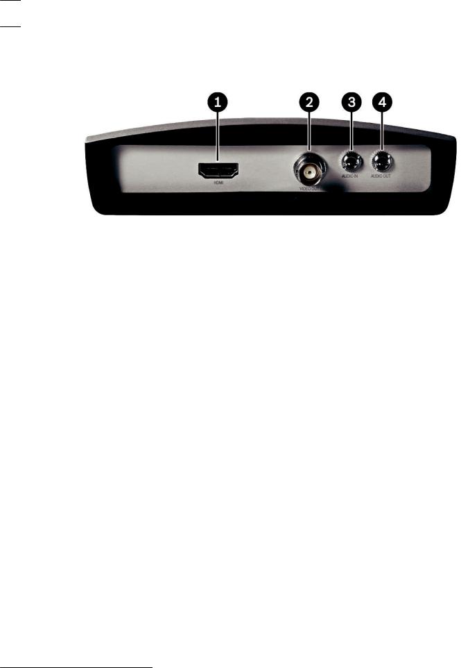
3.4.1 |
Front view |
1HDMI monitor socket
for connecting a computer monitor via HDMI cable
2VIDEO OUT video output
BNC socket for connecting a video monitor
3AUDIO IN audio connection (mono)
3.5 mm (1/8 in) stereo socket audio in for connecting two audio sources
4AUDIO OUT audio connection (mono)
3.5 mm (1/8 in) stereo socket line-out for connecting one audio connection
2014.01 | V4 | F.01U.296.741 |
Installation Manual |
Bosch Sicherheitssysteme GmbH |
VIDEOJET decoder 3000 System overview | en 11
3.4.2 Rear view
1ETH RJ45 socket
for connecting to an Ethernet LAN (local network), 10/100 MBit Base-T
2LED LINK
lights up when the unit is connected to the network
3LED CONNECT
lights up when supplied with power and during data transmission
4Factory reset button
to restore factory default settings
5LED DISPLAY
indicates use of monitor ports
6Terminal block
for alarm inputs, relay output and serial interface
712V DC power connector
for connecting the power supply unit
See also
–LEDs, page 24
–Terminal block, page 25
Bosch Sicherheitssysteme GmbH |
Installation Manual |
2014.01 | V4 | F.01U.296.741 |
Loading...