


OBJ_BUCH-117-003.book Page 1 Wednesday, June 9, 2010 11:30 AM
Robert Bosch GmbH
Power Tools Division
70745 Leinfelden-Echterdingen
Germany
www.bosch-pt.com
1 609 929 W61 (2010.06) T / 217 XXX
S 500 A Professional
de |
Originalbetriebsanleitung |
cs |
Původní návod k používání |
en |
Original instructions |
sk |
Pôvodný návod na použitie |
fr |
Notice originale |
hu |
Eredeti használati utasítás |
es |
Manual original |
ru |
Оригинальное руководство по |
pt |
Manual original |
|
эксплуатации |
it |
Istruzioni originali |
uk |
Оригінальна інструкція з |
nl |
Oorspronkelijke |
|
експлуатації |
|
gebruiksaanwijzing |
ro |
Instrucţiuni originale |
da |
Original brugsanvisning |
bg |
Оригинална инструкция |
sv |
Bruksanvisning i original |
sr |
Originalno uputstvo za rad |
no |
Original driftsinstruks |
sl |
Izvirna navodila |
fi |
Alkuperäiset ohjeet |
hr |
Originalne upute za rad |
el |
Πρωτότυπο οδηγιών χρήσης |
et |
Algupärane kasutusjuhend |
tr |
Orijinal işletme talimat |
lv |
Instrukcijas oriģinālvalodā |
pl |
Instrukcja oryginalna |
lt |
Originali instrukcija |
cn tw
ko
th
id Petunjuk-Petunjuk untuk
Penggunaan Orisinal
vi BΩng hõëng dÿn nguy›n bΩn
ar |
ΔϴϠλϷ ϞϴϐθΘϟ ΕΎϤϴϠόΗ |
fa |
̶Ϡλ έΎ̯ ίήσ ̵ΎϤϨϫέ |
OBJ_BUCH-117-003.book Page 2 Wednesday, June 9, 2010 11:31 AM
2 |
Deutsch . . . . . . . . . . . . . . . . . . . . . . . . |
. . . . Seite |
6 |
English . . . . . . . . . . . . . . . . . . . . . . . . . . |
. . . Page |
12 |
Français . . . . . . . . . . . . . . . . . . . . . . . . . |
. . . Page |
19 |
Español. . . . . . . . . . . . . . . . . . . . . . . . . . |
. .Página |
26 |
Português . . . . . . . . . . . . . . . . . . . . . . . . |
. .Página |
33 |
Italiano . . . . . . . . . . . . . . . . . . . . . . . . . . |
. .Pagina |
39 |
Nederlands . . . . . . . . . . . . . . . . . . . . . . . |
. .Pagina |
46 |
Dansk . . . . . . . . . . . . . . . . . . . . . . . . . . . |
. . . Side |
52 |
Svenska . . . . . . . . . . . . . . . . . . . . . . . . . |
. . . Sida |
57 |
Norsk . . . . . . . . . . . . . . . . . . . . . . . . . . . |
. . . Side |
62 |
Suomi . . . . . . . . . . . . . . . . . . . . . . . . . . . |
. . . .Sivu |
67 |
Ελληνικά . . . . . . . . . . . . . . . . . . . . . . . . . |
. . Σελίδα |
73 |
Türkçe . . . . . . . . . . . . . . . . . . . . . . . . . . |
. . . Sayfa |
80 |
Polski . . . . . . . . . . . . . . . . . . . . . . . . . . . |
. . Strona |
85 |
Česky . . . . . . . . . . . . . . . . . . . . . . . . . . . |
. . Strana |
92 |
Slovensky . . . . . . . . . . . . . . . . . . . . . . . . |
. . Strana |
98 |
Magyar . . . . . . . . . . . . . . . . . . . . . . . . . . |
. . . Oldal |
104 |
Русский . . . . . . . . . . . . . . . . . . . . . . . . |
Страница |
110 |
Українська . . . . . . . . . . . . . . . . . . . . . . . |
Сторінка |
117 |
Română . . . . . . . . . . . . . . . . . . . . . . . . . |
. . Pagina |
124 |
Български . . . . . . . . . . . . . . . . . . . . . . |
Страница |
130 |
Srpski . . . . . . . . . . . . . . . . . . . . . . . . . . . |
. . Strana |
137 |
Slovensko . . . . . . . . . . . . . . . . . . . . . . . . |
. . . Stran |
143 |
Hrvatski . . . . . . . . . . . . . . . . . . . . . . . . . |
Stranica |
149 |
Eesti . . . . . . . . . . . . . . . . . . . . . . . . . . . . |
Lehekülg |
155 |
Latviešu . . . . . . . . . . . . . . . . . . . . . . . . . |
Lappuse |
161 |
Lietuviškai . . . . . . . . . . . . . . . . . . . . . . . |
Puslapis |
167 |
. . . . . . . . . . . . . . . . . . . . . . . . . . . . . |
. . . . . 173 |
|
. . . . . . . . . . . . . . . . . . . . . . . . . . . . . |
. . . . . 178 |
|
. . . . . . . . . . . . . . . . . . . . . . . . . . . |
. . . . . . 183 |
|
. . . . . . . . . . . . . . . . . . . . . . . . . . |
. . . . |
188 |
Bahasa Indonesia . . . . . . . . . . . . . . . . . . |
Halaman |
194 |
Tiøng Vi·t . . . . . . . . . . . . . . . . . . . . . . . . |
. . .Trang |
200 |
. . . . . . . . . . . . . . . . . . . . . . . . . . . . |
. . . ΔΤϔλ |
206 |
vÝ—U . . . . . . . . . . . . . . . . . . . . . . . . . . |
. . . ϪΤϔλ |
211 |
|
|
1 609 929 W61 | (9.6.10) |
|
|
Bosch Power Tools |
|
|
||
|
|
|
|
|
|
|
|
|
|
|
|
|
|
|
|
|
|
|
|
|
|
|
|
|
|
|
|
|
|
OBJ_BUCH-117-003.book Page 3 Wednesday, June 9, 2010 11:31 AM
3 |
|
|
|
|
|
|
|
|
|
|
|
|
|
|
|
|
|
|
|
|
|
|
|
|
|
|
|
|
|
|
|
|
|
|
|
|
|
|
|
|
|
|
|
|
|
|
|
|
|
|
|
|
|
|
|
|
|
|
|
|
|
|
|
|
|
|
|
|
|
|
|
|
|
|
|
|
|
|
|
|
|
|
|
|
|
|
|
|
|
|
|
|
|
|
|
|
|
|
|
|
|
|
|
|
|
|
|
|
|
|
|
|
|
|
1 609 929 W61 | (9.6.10) |
|
Bosch Power Tools |
|
|
|||||||
|
|
|
|
|
|
|
|
|
|
|
|
|
|
|
|
|
|
|
|
|
|
|
|
|
|
|
|
|
|
|
|
|
|
|
|
|
|
|
|
|
|
OBJ_BUCH-117-003.book Page 4 Wednesday, June 9, 2010 11:31 AM
4 | |
|
|
A |
|
B |
12 |
|
|
|
|
13 |
|
12 |
12 |
|
13 |
|
|
|
|
C |
|
D |
23 |
|
|
|
|
24 |
|
|
25 |
1 609 929 W61 | (9.6.10) |
|
Bosch Power Tools |

OBJ_BUCH-117-003.book Page 5 Wednesday, June 9, 2010 11:31 AM |
|
|
5 | |
|
|
E |
F |
|
|
|
20 |
|
|
21 |
|
|
22 |
G |
H |
|
|
|
2 |
|
|
26 |
3 |
17 |
27 |
|
||
6 |
|
|
7 |
|
8 |
|
|
|
8 |
|
|
|
|
28 |
1 609 929 W61 | (9.6.10) |
|
Bosch Power Tools |
OBJ_BUCH-117-003.book Page 6 Wednesday, June 9, 2010 11:31 AM
6 | Deutsch
Sicherheitshinweise
 WARNUNG Lesen Sie alle Sicherheitshinweise und Anweisungen, die
mit dem Bohrständer oder der Bohrmaschine geliefert wurden. Versäumnisse bei der Einhaltung der Sicherheitshinweise und Anweisungen können elektrischen Schlag, Brand und/oder schwere Verletzungen verursachen.
Bewahren Sie alle Sicherheitshinweise und Anweisungen für die Zukunft auf.
fZiehen Sie den Stecker aus der Steckdose, bevor Sie Geräteeinstellungen vornehmen oder Zubehörteile wechseln. Unbeabsichtigter Start von Bohrmaschinen ist die Ursache einiger Unfälle.
fBauen Sie vor der Montage der Bohrmaschine den Bohrständer richtig auf. Richtiger Zusammenbau ist wichtig, um die einwandfreie Funktion zu gewährleisten.
fBefestigen Sie die Bohrmaschine sicher am Bohrständer, bevor Sie sie benutzen. Ein Verrutschen der Bohrmaschine im Bohrständer kann zum Verlust der Kontrolle führen.
fBefestigen Sie den Bohrständer auf einer festen, ebenen Fläche. Wenn der Bohrständer verrutschen oder wackeln kann, kann die Bohrmaschine nicht gleichmäßig und sicher geführt werden.
fÜberlasten Sie den Bohrständer nicht und verwenden Sie ihn nicht als Leiter oder Gerüst. Überlastung oder Stehen auf dem Bohrständer kann dazu führen, dass sich der Schwerpunkt des Bohrständers nach oben verlagert und er umkippt.
fHalten Sie Ihren Arbeitsbereich sauber und gut beleuchtet. Unordnung oder unbeleuchtete Arbeitsbereiche können zu Unfällen führen.
fEntfernen Sie Einstellwerkzeuge oder Schraubenschlüssel, bevor Sie das Gerät einschalten. Ein Werkzeug oder Schlüssel, der sich in einem drehenden Geräteteil befindet, kann zu Verletzungen führen.
fVermeiden Sie eine abnormale Körperhaltung. Sorgen Sie für einen sicheren Stand und halten Sie jederzeit das Gleichgewicht.
Dadurch können Sie das Elektrowerkzeug in unerwarteten Situationen besser kontrollieren.
fPflegen Sie den Bohrständer mit Sorgfalt. Kontrollieren Sie, ob bewegliche Geräteteile einwandfrei funktionieren und nicht klemmen, ob Teile gebrochen oder so beschädigt sind, dass die Funktion des Bohrständers beeinträchtigt ist. Lassen Sie beschädigte Teile vor dem Einsatz des Bohrständers reparieren. Viele Unfälle haben ihre Ursache in schlecht gewarteten Geräten.
fBewahren Sie unbenutzte Bohrständer außerhalb der Reichweite von Kindern auf. Lassen Sie Personen das Gerät nicht benutzen, die mit diesem nicht vertraut sind oder diese Anweisungen nicht gelesen haben.
Geräte sind gefährlich, wenn sie von unerfahrenen Personen benutzt werden.
fLassen Sie den Bohrständer nur von qualifiziertem Fachpersonal und nur mit OriginalErsatzteilen reparieren. Damit wird sichergestellt, dass die Sicherheit des Gerätes erhalten bleibt.
fFassen Sie den Bohrständer an den isolierten Griffflächen an, wenn Sie Arbeiten ausführen, bei denen das Einsatzwerkzeug verborgene Stromleitungen oder das eigene Netzkabel treffen kann. Der Kontakt mit einer spannungsführenden Leitung kann auch Metallteile des Bohrständers unter Spannung setzen und zu einem elektrischen Schlag führen.
fDie Sicherheitsund Arbeitshinweise für die eingesetzte Bohrmaschine und das verwendete Zubehör sind strikt zu beachten!
fSichern Sie vor allen Arbeiten an Bohrständer oder Bohrmaschine, in Arbeitspausen sowie bei Nichtgebrauch den Bohrständer durch Einrasten der Vorschubarretierung 3 gegen unbeabsichtigtes Bewegen.
|
|
1 609 929 W61 | (9.6.10) |
|
|
Bosch Power Tools |
|
|
||
|
|
|
|
|
|
|
|
|
|
|
|
|
|
|
|
|
|
|
|
|
|
|
|
|
|
|
|
|
|
OBJ_BUCH-117-003.book Page 7 Wednesday, June 9, 2010 11:31 AM
Funktionsbeschreibung
Lesen Sie alle Sicherheitshinweise und Anweisungen. Versäumnisse
bei der Einhaltung der Sicherheits-
hinweise und Anweisungen können elektrischen Schlag, Brand und/oder schwere Verletzungen verursachen.
Bitte klappen Sie die Aufklappseite mit der Darstellung des Bohrständers auf, und lassen Sie diese Seite aufgeklappt, während Sie die Betriebsanleitung lesen.
Bestimmungsgemäßer Gebrauch
Der Diamantbohrständer ist zur Aufnahme von Bosch-Diamantbohrmaschinen bestimmt. Andere Geräte dürfen nicht eingesetzt werden.
Der Diamantbohrständer kann mithilfe von Dübel oder Schnellspannsäule am Boden und an der Wand angebracht werden. In Kombination mit den Diamantbohrmaschinen GDB 1600 WE oder GDB 1600 DE kann der Bohrständer auch über Kopf befestigt werden.
Abgebildete Komponenten
Die Nummerierung der abgebildeten Komponenten bezieht sich auf die Darstellung des Bohrständers auf der Grafikseite.
1Transportgriff
2Bohrsäule
3Vorschubarretierung
4Libelle für senkrechtes Ausrichten
5Libelle für waagerechtes Ausrichten
6Oberer Knebelgriff an der Geräteaufnahme
7Unterer Knebelgriff an der Geräteaufnahme
8Geräteaufnahme
9Zahnstange
10Bohrloch-Mittenanzeiger
11Nivellierschraube
12Stützwinkel
13Rändelschraube für Stützwinkel
14Sechskantschraube für Transporträder
15Transporträder
16Arretierstift der Vorschubkurbel
17Vorschubkurbel
18Handgriff (isolierte Grifffläche)
Deutsch | 7
19Winkelskala
20Arretierknopf der Bohrwinkel-Verstellung
21Oberer Knebelgriff der Bohrwinkel-Verstel- lung
22Unterer Knebelgriff der Bohrwinkel-Verstel- lung
23Mauerwerksdübel*
24Schnellspannspindel*
25Flügelmutter*
26Gleitelemente
27Innensechskantschrauben der Geräteaufnahme
28Stellschrauben der Geräteaufnahme
*Abgebildetes oder beschriebenes Zubehör gehört nicht zum Standard-Lieferumfang. Das vollständige Zubehör finden Sie in unserem Zubehörprogramm.
Technische Daten
Diamantbohrständer |
|
S 500 A |
|
|
Professional |
Sachnummer |
|
0 601 190 025 |
Maße |
|
|
– Höhe |
mm |
1010 |
– Breite |
mm |
280 |
– Tiefe |
mm |
465 (400*) |
– Bohrsäulenlänge |
mm |
1000 |
Bohrhub max. |
mm |
500 |
max. Bohrdurchmesser |
|
|
in Beton mit |
|
|
– GDB 1600 WE** |
mm |
102 |
– GDB 2500 WE*** |
mm |
212 |
max. Bohrdurchmesser |
|
|
in Mauerwerk mit |
|
|
– GDB 1600 WE/DE** |
mm |
152 |
– GDB 2500 WE*** |
mm |
152 |
Gewicht entsprechend |
|
|
EPTA-Procedure |
|
|
01/2003 |
kg |
12,5 |
|
|
|
*mit nach hinten montierten Stützwinkeln
**mit Saugkopf
***auch mit Wasserfangring (Zubehör) möglich
Bitte beachten Sie die Sachnummer auf dem Typenschild Ihres Bohrständers. Die Handelsbezeichnungen einzelner Bohrständer können variieren.
|
|
Bosch Power Tools |
|
|
1 609 929 W61 | (9.6.10) |
|
|
||
|
|
|
|
|
|
|
|
|
|
|
|
|
|
|
|
|
|
|
|
|
|
|
|
|
|
|
|
|
|
OBJ_BUCH-117-003.book Page 8 Wednesday, June 9, 2010 11:31 AM
8 | Deutsch
Konformitätserklärung
Wir erklären in alleiniger Verantwortung, dass das unter „Technische Daten“ beschriebene Produkt den Bestimmungen der Richtlinie 2006/42/EG entspricht.
Technische Unterlagen bei: Robert Bosch GmbH, PT/ESC, D-70745 Leinfelden-Echterdingen
Dr. Egbert Schneider |
Dr. Eckerhard Strötgen |
Senior Vice President |
Head of Product |
Engineering |
Certification |
Robert Bosch GmbH, Power Tools Division
D-70745 Leinfelden-Echterdingen
Leinfelden, 22.04.2010
Montage
Bohrständer montieren
Stützwinkel
Sie können die Stützwinkel 12 in zwei Stellungen montieren:
–Die Grundstellung (siehe Bild A) ist notwendig, wenn die GDB 2500 WE in den Bohrständer eingesetzt und der Bohrständer nicht mit Dübel oder Schnellspannsäule sicher befestigt ist.
–Die Platz sparende Stellung (siehe Bild B) ist nur möglich bei Einsatz der GDB 1600 WE/DE oder bei sicher an der Wand befestigtem Bohrständer. Die Montage des Wasserfangringes (Zubehör) für die GDB 2500 WE ist in dieser Stellung nicht möglich.
Zum Wechsel zwischen beiden Stellungen lösen Sie die Rändelschrauben 13, versetzen die Stützwinkel 12 in die gewünschte Position und schrauben sie mit den Rändelschrauben wieder fest.
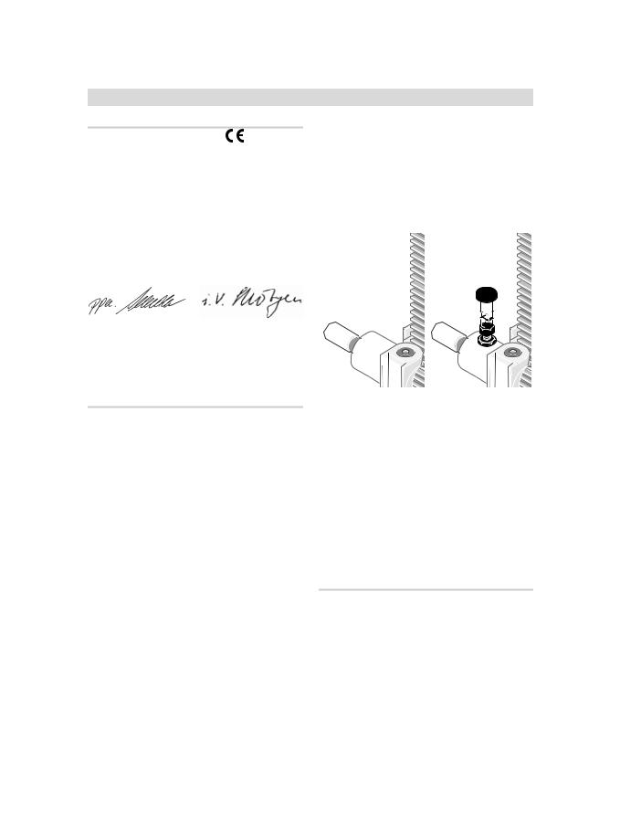
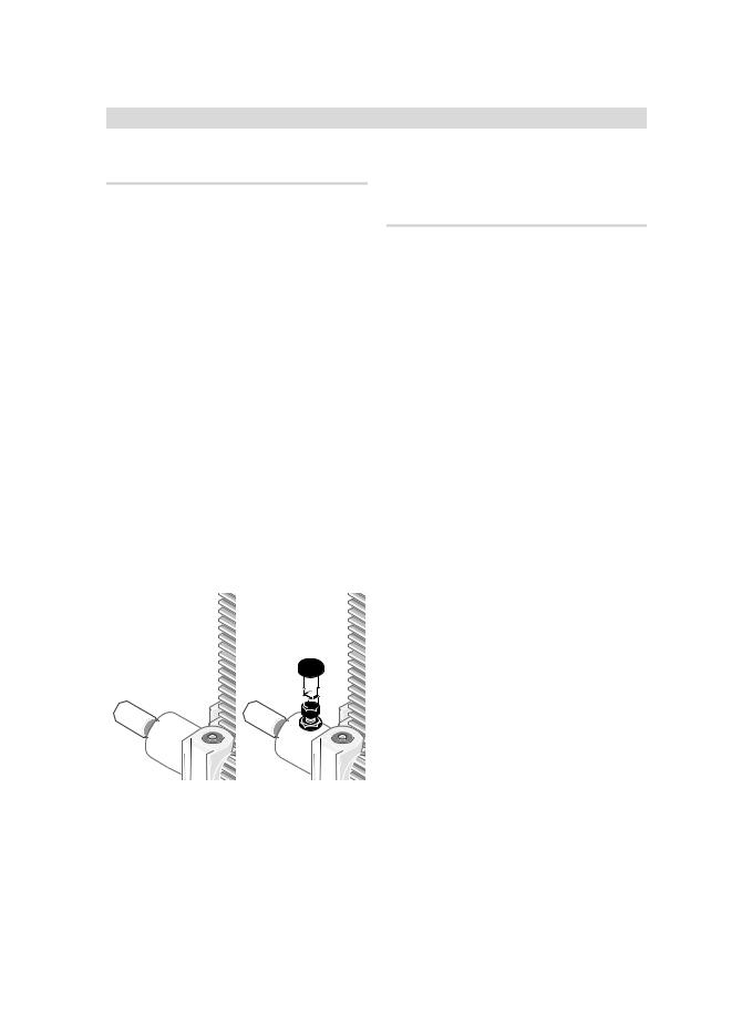
Vorschubkurbel
Drücken Sie den Arretierstift 16 an der Vorschubkurbel und halten Sie ihn gedrückt. Schieben Sie die Vorschubkurbel 17 je nach Bedarf links oder rechts von der Geräteaufnahme 8 bis zum Anschlag auf.
Lassen Sie den Arretierstift 16 los und prüfen Sie die Vorschubkurbel auf festen Sitz.
1 |
|
|
A |
2 |
A |
|
|
|
|
||
|
|
|
|
|
|
|
|
3 |
|
|
3 |
|
B |
|
|
B |
|
|
|
|
|
||
|
|
|
|
|
Blockieren Sie anschließend den Vorschub: Ziehen Sie die Vorschubarretierung 3 nach oben
(A), drehen Sie sie (B) und lassen Sie sie in Stellung c einrasten. Drehen Sie bei Bedarf die Vorschubkurbel 17 leicht, bis die Arretierung hörbar einrastet.
Lösen Sie den Vorschub nur zum Bohren: Ziehen Sie die Vorschubarretierung 3 nach oben (A), drehen Sie sie (B) und lassen Sie sie in Stellung d einrasten.
Transporträder
Schrauben Sie zum Transport des Bohrständers die Transporträder 15 mit den Sechskantschrauben 14 an den Seiten des Bohrständers fest.
Bohrständer befestigen
Hinweis: Befestigen Sie den Bohrständer spielfrei. So vermeiden Sie ein Verklemmen der Bohrkrone und damit Segmentabriss.
Befestigen Sie je nach Art und Beschaffenheit des Untergrundes den Bohrständer mit Dübel oder Schnellspannsäule am geplanten Bohrloch.
|
|
1 609 929 W61 | (9.6.10) |
|
|
Bosch Power Tools |
|
|
||
|
|
|
|
|
|
|
|
|
|
|
|
|
|
|
|
|
|
|
|
|
|
|
|
|
|
|
|
|
|

OBJ_BUCH-117-003.book Page 9 Wednesday, June 9, 2010 11:31 AM
Bohrständer vor der Befestigung positionieren
10 |
10 |
GDB 2500 WE |
GDB 1600 WE/DE |
Klappen Sie den Bohrloch-Mittenanzeiger 10 aus. Bringen Sie bei Verwendung der
GDB 2500 WE die Spitze des Bohrloch-Mitten- anzeigers mit der angezeichneten Mitte des geplanten Bohrlochs zur Deckung. Bei Verwendung der GDB 1600 WE/DE ist die Innenkante des Bohrloch-Mittenanzeigers 10 der Bezugspunkt.
Verschieben Sie bei Schrägbohrungen den Bohrständer um den Wert m von der Bohrlochmitte:
|
Bohrwinkel |
m |
m* |
0° |
0 mm |
m** |
15° |
30 mm |
|
30° |
80 mm |
|
45° |
160 mm |
|
m* : GDB 2500 WE |
|
|
m**: GDB 1600 WE/DE |
|
Befestigen Sie den Bohrständer mit Dübel oder Schnellspannsäule. Klappen Sie dann den Bohr- loch-Mittenanzeiger 10 ein.
Deutsch | 9
Befestigung mit Dübel (siehe Bild C)
Bohren Sie für die Befestigung des Bohrständers mit Dübel (Zubehör) in Mauerwerk oder Beton ein separates Befestigungsloch.
Abstand Dübelloch–Mitte des geplanten Bohrlochs
|
optimal |
möglich |
GDB 2500 WE |
330 mm |
310–380 mm |
GDB 1600 WE/DE |
270 mm |
250–320 mm |
Vergrößern Sie bei Schrägbohrungen den Abstand zwischen dem Dübelloch und der Mitte des geplanten Bohrlochs um den Wert m (siehe „Bohrständer vor der Befestigung positionieren“).
Für das Dübelloch gelten folgende Maße:
|
Durchmesser |
Tiefe |
Mauerwerk |
20 mm |
85 mm |
Beton |
15 mm |
50 mm |
Setzen Sie einen Betondübel mit Spreizkeil bzw. einen Mauerwerksdübel 23 ein. Schrauben Sie die Schnellspannspindel 24 in den Dübel.
Setzen Sie den Bohrständer sowie eine Unterlegscheibe auf und schrauben Sie sie mit der Flügelmutter 25 an. Ziehen Sie die Flügelmutter nach der Nivellierung (siehe „Nivellieren“) mit einem Gabelschlüssel (Schlüsselweite 27 mm) fest.
Befestigung mit einer Schnellspannsäule (siehe Bild D und E)
Sie können den Bohrständer mit einer BoschSchnellspannsäule (Zubehör) zwischen Boden und Decke oder zwischen zwei Wänden befestigen. Der Spannbereich liegt zwischen 1,7 m und 3 m.
Setzen Sie ein Ende der Schnellspannsäule auf die Bodenplatte des Bohrständers auf. Die Aufsetzfläche für das andere Ende der Schnellspannsäule auf der Wand muss ausreichend stabil und sicher gegen Verrutschen sein.
Für die Befestigung der Schnellspannsäule lesen und befolgen Sie deren Betriebsanleitung.
|
|
Bosch Power Tools |
|
|
1 609 929 W61 | (9.6.10) |
|
|
||
|
|
|
|
|
|
|
|
|
|
|
|
|
|
|
|
|
|
|
|
|
|
|
|
|
|
|
|
|
|
OBJ_BUCH-117-003.book Page 10 Wednesday, June 9, 2010 11:31 AM
10 | Deutsch
Nivellieren
Drehen Sie die Nivellierschrauben 11 einzeln so weit ein bzw. heraus, bis die Libelle 4 (bei senkrechter Montage) bzw. die Libelle 5 (bei waagerechter Montage) exakt ausgerichtet ist.
Fixieren Sie nun den Bohrständer fest mit Dübelbefestigung oder Schnellspannsäule.
Betrieb
fZiehen Sie nach jeder Verstellung am Bohrständer Schrauben und Knebelgriffe wieder gut fest und lassen Sie die Arretierungen wieder einrasten.
Bohrwinkel ändern (siehe Bild F)
Lösen Sie den oberen Knebelgriff 21 und den unteren Knebelgriff 22 der Winkelverstellung.
Ziehen Sie den Arretierknopf 20. Stellen Sie den Bohrständer auf einen der vier möglichen Bohrwinkel (0°, 15°, 30° oder 45°) und lassen Sie den Arretierknopf in der entsprechenden Vertiefung der Bohrsäule einrasten.
Ziehen Sie die beiden Knebelgriffe 21 und 22 wieder fest.
fDer Bohrständer darf erst eingesetzt werden, wenn beide Knebelgriffe der Winkelverstellung wieder festgezogen sind.
Wasserabsaugung
Um das beim Nassbohren aus der Bohrung austretende Wasser aufzufangen, benötigen Sie einen Wasserfangring und einen Allzwecksauger (beide Zubehör).
Die Auswahl des Wasserfangringes richtet sich nach der eingesetzten Diamantbohrmaschine (GDB 2500 WE oder GDB 1600 WE/DE).
Zur Montage des Wasserfangringes lesen und befolgen Sie dessen Betriebsanleitung.
Arbeitshinweise
fBeachten Sie zum Bohren die Betriebsanleitung Ihrer Diamantbohrmaschine.
Lösen Sie zum Bohren die Arretierung der Vorschubkurbel 17 (siehe „Vorschubkurbel“).
Drehen Sie mit der Vorschubkurbel die Bohrmaschine bis zur gewünschten Bohrtiefe herunter.
Drehen Sie danach zurück, bis die Bohrkrone vollständig sichtbar ist.
Wartung und Service
Wartung und Reinigung
Halten Sie die Zahnstange 9 und die Führungsflächen der Bohrsäule 2 stets sauber.
Diamantbohrmaschine einsetzen (siehe Bild G)
Lösen Sie die Knebelgriffe 6 und 7 am Bohrständer. Achten Sie darauf, dass die Vorschubkurbel 17 durch die Vorschubarretierung 3 blockiert ist (siehe „Vorschubkurbel“).
Setzen Sie das Elektrowerkzeug von oben bis zum Anschlag in die Geräteaufnahme 8 des Bohrständers ein. Ziehen Sie die Knebelgriffe 6 und 7 wieder fest. Beim Einsetzen der
GDB 1600 WE/DE wird der obere Knebelgriff 6 nicht benötigt.
Legen Sie den Wasserschlauch und das Netzkabel des Elektrowerkzeuges in die Halterungen an der Geräteaufnahme des Bohrständers ein.
Gehen Sie beim Entnehmen des Elektrowerkzeuges aus dem Bohrständer in umgekehrter Reihenfolge vor.
Geräteaufnahme nachstellen (siehe Bild H)
Um gute Bohrergebnisse zu erzielen, muss das Spiel zwischen Geräteaufnahme 8 und Bohrsäule 2 so gering wie möglich sein.
Lösen Sie zum Nachstellen die vier Innensechskantschrauben 27. Ziehen Sie die Gleitelemente 26 mit leichtem Druck durch Drehen der beiden Stellschrauben 28 an die Bohrsäule. Achten Sie darauf, dass die Geräteaufnahme parallel zur Bohrsäule ausgerichtet ist.
Wenn das Gleitverhalten ausreichend ist, fixieren Sie die Stellschrauben 28 durch Anziehen der Innensechskantschrauben 27.
|
|
1 609 929 W61 | (9.6.10) |
|
|
Bosch Power Tools |
|
|
||
|
|
|
|
|
|
|
|
|
|
|
|
|
|
|
|
|
|
|
|
|
|
|
|
|
|
|
|
|
|
OBJ_BUCH-117-003.book Page 11 Wednesday, June 9, 2010 11:31 AM
Sollte der Bohrständer trotz sorgfältiger Herstellungsund Prüfverfahren einmal ausfallen, ist die Reparatur von einer autorisierten Kundendienststelle für Bosch-Elektrowerkzeuge ausführen zu lassen.
Geben Sie bei allen Rückfragen und Ersatzteilbestellungen bitte unbedingt die 10-stellige Sachnummer laut Typenschild des Bohrständers an.
Zubehör
Transporträder. . . . . . . . . . . . . . 2 609 390 309
Befestigungsset:
–für Beton. . . . . . . . . . . . . . . . 2 607 000 744
–für Mauerwerk . . . . . . . . . . . 2 607 000 745
Schnellspannsäule . . . . . . . . . . . 2 608 598 111 Verwendung mit GDB 2500 WE:
–Wasserfangring . . . . . . . . . . . 2 609 390 389
–Dichtungsdeckel für
Wasserfangring . . . . . . . . . . . 2 609 390 391
Verwendung mit GDB 1600 WE:
–Wasserfangring . . . . . . . . . . . 2 609 390 310
–Dichtungsdeckel für
Wasserfangring . . . . . . . . . . . 2 609 390 311
Kundendienst und Kundenberatung
Der Kundendienst beantwortet Ihre Fragen zu Reparatur und Wartung Ihres Produkts sowie zu Ersatzteilen. Explosionszeichnungen und Informationen zu Ersatzteilen finden Sie auch unter: www.bosch-pt.com
Das Bosch-Kundenberater-Team hilft Ihnen gerne bei Fragen zu Kauf, Anwendung und Einstellung von Produkten und Zubehören.
www.powertool-portal.de, das Internetportal für Handwerker und Heimwerker. www.ewbc.de, der Informations-Pool für Handwerk und Ausbildung.
Deutsch | 11
Deutschland
Robert Bosch GmbH Servicezentrum Elektrowerkzeuge Zur Luhne 2
37589 Kalefeld – Willershausen
Tel. Kundendienst: +49 (1805) 70 74 10* Fax: +49 (1805) 70 74 11*
(*Festnetzpreis 14 ct/min, höchstens 42 ct/min aus Mobilfunknetzen)
E-Mail: Servicezentrum.Elektrowerkzeuge@de.bosch.com Tel. Kundenberatung: +49 (1803) 33 57 99 (Festnetzpreis 9 ct/min, höchstens 42 ct/min aus Mobilfunknetzen)
Fax: +49 (711) 7 58 19 30
E-Mail: kundenberatung.ew@de.bosch.com
Österreich
Tel.: +43 (01) 7 97 22 20 10
Fax: +43 (01) 7 97 22 20 11
E-Mail: service.elektrowerkzeuge@at.bosch.com
Schweiz
Tel.: +41 (044) 8 47 15 11
Fax: +41 (044) 8 47 15 51
Luxemburg
Tel.: +32 (070) 22 55 65
Fax: +32 (070) 22 55 75
E-Mail: outillage.gereedschap@be.bosch.com
Weitere Informationen zum Diamantbohren finden Sie unter www.bosch-diamond.com.
Entsorgung
Bohrständer, Zubehör und Verpackungen sollen einer umweltgerechten Wiederverwertung zugeführt werden.
Änderungen vorbehalten.
|
|
Bosch Power Tools |
|
|
1 609 929 W61 | (9.6.10) |
|
|
||
|
|
|
|
|
|
|
|
|
|
|
|
|
|
|
|
|
|
|
|
|
|
|
|
|
|
|
|
|
|
OBJ_BUCH-117-003.book Page 12 Wednesday, June 9, 2010 11:31 AM
12 | English
Safety Notes
 WARNING Read all safety warnings and instructions that were provided
with the drill stand or the drill. Failure to follow the safety warnings and the instructions may result in electric shock, fire and/or serious injury.
Save all safety warnings and instructions for future reference.
fDisconnect the plug from the power source before making any adjustments or changing accessories. Starting drills accidentally is the cause of some accidents.
fAssemble the drill stand properly before mounting the drill. The correct assembly is important in order to ensure proper function.
fBefore using, fasten the drill securely to the drill stand. An unsecured drill in the drill stand can lead to loss of control.
fFasten the drill stand on a firm and level surface. When the drill stand can slip away or wobble, then the drill cannot be guided uniformly and securely.
fDo not overload the drill stand and do not use it as a ladder or scaffold. Overloading or standing on the drill stand can raise the drill stand’s centre of gravity and cause it to tip over.
fKeep work area clean and well lit. Cluttered or dark areas invite accidents.
fRemove any adjusting key or wrench before turning the power tool on. A wrench or a key left attached to a rotating part of the power tool may result in personal injury.
fAvoid abnormal body posture. Provide for a secure stance and keep your balance at all times. In this manner, you can control the power tool better in unexpected situations.
fMaintain the drill stand with care. Check for misalignment or binding of moving parts, breakage of parts and any other condition that may affect the function of the drill stand. Have damaged parts repaired before using the drill stand. Many accidents are caused by poorly maintained devices.
fStore idle drill stands out of the reach of children and do not allow persons unfamiliar with the device or these instructions to operate the device. Drill stands are dangerous in the hands of untrained users.
fHave your drill stand serviced/repaired only by a qualified repair person using original replacement parts. This will ensure that the safety of the device is maintained.
fHold the drill stand by the insulated gripping surfaces when performing operations where the application tool could contact hidden wiring or its own power cord. Contact with a “live” wire will also make exposed metal parts of the drill stand “live” and shock the operator.
fThe safety and operating instructions for the drill and the accessories being used are strictly to be observed!
fBefore any work on the drill stand or the drill, during work breaks as well as when not using for extending periods, secure the drill stand against unintentional moving by engaging the feed lock 3.
Functional Description
Read all safety warnings and all instructions. Failure to follow the
warnings and instructions may re-
sult in electric shock, fire and/or serious injury.
While reading the operating instructions, unfold the fold-out page with the illustration of the drill stand and leave it open.
Intended Use
The drill stand for diamond drills is intended for mounting Bosch diamond drills. Other machines may not be mounted.
The drill stand for diamond drills can be fastened to a wall or floor with anchor and quickclamping spindle. In combination with the diamond drills GDB 1600 WE or GDB 1600 DE, the drill stand can also be fastened overhead.
|
|
1 609 929 W61 | (9.6.10) |
|
|
Bosch Power Tools |
|
|
||
|
|
|
|
|
|
|
|
|
|
|
|
|
|
|
|
|
|
|
|
|
|
|
|
|
|
|
|
|
|
OBJ_BUCH-117-003.book Page 13 Wednesday, June 9, 2010 11:31 AM
Product Features
The numbering of the illustrated product features refers to the representation of the drill stand on the graphics page.
1Transport handle
2Drilling column
3Feed lock
4Spirit level for vertical alignment
5Spirit level for horizontal alignment
6Upper locking handle on drill fixture
7Lower locking handle on drill fixture
8Drill fixture
9Rack
10Drill-hole centre indicator
11Levelling screw
12Supporting bracket
13Knurled screw for supporting bracket
14Hexagon screw for transport wheels
15Transport wheels
16Lock pin for feed feed handle
17Feed handle
18Handle (insulated gripping surface)
19Angle scale
20Lock button for drill-angle adjustment
21Upper locking handle for drill-angle adjustment
22Lower locking handle for drill-angle adjustment
23Brickwork anchor*
24Quick-clamping spindle*
25Wing nut*
26Sliding elements
27Allen screws of the drill fixture
28Adjusting screws of the drill fixture
*Accessories shown or described are not part of the standard delivery scope of the product. A complete overview of accessories can be found in our accessories program.
|
|
English | 13 |
|
|
|
Technical Data |
|
|
|
|
|
Drill stand for diamond drills |
S 500 A |
|
|
|
Professional |
Article number |
|
0 601 190 025 |
Dimensions |
|
|
– Height |
mm |
1010 |
– Width |
mm |
280 |
– Depth |
mm |
465 (400*) |
– Length of drilling |
|
|
column |
mm |
1000 |
Drill stroke, max. |
mm |
500 |
Drilling diameter (max.) |
|
|
in concrete with |
|
|
– GDB 1600 WE** |
mm |
102 |
– GDB 2500 WE*** |
mm |
212 |
Drilling diameter (max.) |
|
|
in brickwork with |
|
|
– GDB 1600 WE/DE** |
mm |
152 |
– GDB 2500 WE*** |
mm |
152 |
Weight according to |
|
|
EPTA-Procedure |
|
|
01/2003 |
kg |
12.5 |
|
|
|
*with supporting angles mounted to the rear
**with suction head
***also possible with water collection ring (accessory)
Please observe the article number on the type plate of your drill stand. The trade names of individual drill stands may vary.
Declaration of Conformity
We declare under our sole responsibility, that the product described under “Technical data” is in conformity with the provisions of the directive 2006/42/EC.
Technical file at:
Robert Bosch GmbH, PT/ESC, D-70745 Leinfelden-Echterdingen
Dr. Egbert Schneider |
Dr. Eckerhard Strötgen |
Senior Vice President |
Head of Product |
Engineering |
Certification |
Robert Bosch GmbH, Power Tools Division
D-70745 Leinfelden-Echterdingen
Leinfelden, 22.04.2010
|
|
Bosch Power Tools |
|
|
1 609 929 W61 | (9.6.10) |
|
|
||
|
|
|
|
|
|
|
|
|
|
|
|
|
|
|
|
|
|
|
|
|
|
|
|
|
|
|
|
|
|
OBJ_BUCH-117-003.book Page 14 Wednesday, June 9, 2010 11:31 AM
14 | English
Assembly
Mounting the Drill Stand
Supporting Angles
Transport Wheels
For transport of the drill stand, screw the transport wheels 15 to the sides of the drill stand with the hexagon screws 14.
The supporting angles 12 can be mounted in two positions:
–The basic position (see Fig. A) is necessary when the GDB 2500 WE is installed into the drill stand and the drill stand is not securely mounted via anchor or quick-clamping column.
–The space-saving position (see Fig. B) is only possible when using the GDB 1600 WE/DE or when the drill stand is securely fastened to the wall. Assembly of the water collection ring (accessory) for the GDB 2500 WE is not possible in this position.
To switch between both positions, loosen the knurled screws 13, adjust the supporting angles 12 to the required position and tighten them again with the knurled screws.
Feed Handle
Press the lock pin 16 on the feed handle and keep it pressed. Slide the feed handle 17 to the stop left or right of the drill fixture 8 as required.
Release the lock pin 16 and check the feed handle for tight seating.
1 |
|
|
A |
2 |
A |
|
|
|
|
||
|
|
|
|
|
|
|
|
3 |
|
|
3 |
|
B |
|
|
B |
|
|
|
|
|
||
|
|
|
|
|
Afterwards, block the feed: Pull the feed lock 3 upward (A), turn it (B) and allow it to engage in position c. If required, lightly rotate the feed handle 17 until the lock can be heard to engage.
Release the feed only for drilling: Pull the feed lock 3 upward (A), turn it (B) and allow it to engage in position d.
Fastening the Drill Stand
Note: Fasten the drill stand free from play to prevent jamming of the core bit and the tearing out of segments.
Depending on the type and surface quality, fasten the drill stand with anchor or quick-clamp- ing column at the planned drill hole.
Positioning the Drill Stand before Fastening
10 |
10 |
GDB 2500 WE |
GDB 1600 WE/DE |
Fold out the drill-hole centre indicator 10. When working with the GDB 2500 WE, bring the tip of the drill-hole centre indicator into alignment with the marked centre of the intended bore hole. When working with the GDB 1600 WE/DE, the inner edge of the drill-hole centre indicator 10 is the reference point.
For offset drilling, move the drill stand away from the bore hole centre by the value m:
|
Drilling angle |
m |
m* |
0° |
0 mm |
m** |
15° |
30 mm |
|
30° |
80 mm |
|
45° |
160 mm |
|
m*: GDB 2500 WE |
|
|
m**: GDB 1600 WE/DE |
|
|
|
1 609 929 W61 | (9.6.10) |
|
|
Bosch Power Tools |
|
|
||
|
|
|
|
|
|
|
|
|
|
|
|
|
|
|
|
|
|
|
|
|
|
|
|
|
|
|
|
|
|
OBJ_BUCH-117-003.book Page 15 Wednesday, June 9, 2010 11:31 AM
Fasten the drill stand with anchor or quickclamping column. Then fold in the drill-hole centre indicator 10.
Fastening with Anchor (see figure C)
For fastening of the drill stand to brickwork or concrete with anchor (accessory), drill a separate anchor hole.
Clearance from anchor hole–centre of the intended bore hole
|
optimal |
possible |
GDB 2500 WE |
330 mm |
310–380 mm |
GDB 1600 WE/DE |
270 mm |
250–320 mm |
For offset bore drilling, increase the distance between the anchor hole and the centre of the intended bore hole by the value m (see “Positioning the Drill Stand before Fastening”).
The following dimensions apply for the anchor hole:
|
Diameter |
Depth |
Brickwork |
20 mm |
85 mm |
Concrete |
15 mm |
50 mm |
Insert a concrete hammer-drive anchor or a brickwork anchor 23. Screw the quick-clamping spindle 24 into the anchor.
Position the drill stand, attach a washer, and then screw together with the wing nut 25. After levelling (see “Levelling”), tighten the wing nut using an open-end spanner, size 27 mm.
Fastening with a Quick-clamping Column (see figure D and E)
With use of a Bosch quick-clamping column (accessory), the drill stand can be fastened between ceiling and floor or between two walls. The clamping range is between 1.7 m and 3 m.
Position one end of the quick-clamping column onto the base plate of the drill stand. The mounting surface for the other end of the quickclamping column against the wall must have sufficient stability and be secure against slipping.
For fastening the quick-clamping column, read and observe its operating instructions.
English | 15
Levelling
Screw the levelling screws 11 in or out individually, until the spirit level 4 (for vertical assembly) or the spirit level 5 (for horizontal assembly) is precisely aligned.
Now, firmly fasten the drill stand with anchor attachment or with the quick-clamping column.
Operation
fAfter each adjustment on the drill stand, firmly retighten all screws and locking handles and allow the locks to engage again.
Drilling-angle Adjustment (see figure F)
Loosen the upper 21 and the lower locking handle 22 for drill-angle adjustment.
Pull the lock button for drill-angle adjustment 20. Adjust the drill stand to one of the four possible drilling angles (0°, 15°, 30° or 45°) and allow the lock button to engage into the corresponding hole in the drilling column.
Tighten both locking handles 21 and 22 again.
fThe drill stand may not be used until both locking handles of the angle adjustment have been tightened again.
Mounting the Diamond Drill (see figure G)
Loosen the locking handles 6 and 7 on the drill stand. Pay attention that the feed handle 17 is blocked by the feed lock 3 (see “Feed Handle”).
Insert the power tool from above into the drill fixture 8 down to the stop. Retighten the locking handles 6 and 7 again. When mounting the GDB 1600 WE/DE, the upper locking handle 6 is not required.
Place the water hose and the mains cable of the power tool into the holders of the drill fixture on the drill stand.
Proceed in reverse order when removing the power tool from the drill stand.
|
|
Bosch Power Tools |
|
|
1 609 929 W61 | (9.6.10) |
|
|
||
|
|
|
|
|
|
|
|
|
|
|
|
|
|
|
|
|
|
|
|
|
|
|
|
|
|
|
|
|
|
OBJ_BUCH-117-003.book Page 16 Wednesday, June 9, 2010 11:31 AM
16 | English
Water Extraction
In order to collect the water coming out of the bore during wet-drilling, a water collection ring and a multi-purpose vacuum cleaner are required (both accessories).
The choice of the water collection ring depends on the diamond drill (GDB 2500 WE or
GDB 1600 WE/DE) being used.
For assembly of the water collection ring, read and observe its operating instructions.
Working Advice
fFor drilling, observe the operating instructions of your diamond drill.
For drilling, loosen the lock pin for the feed handle 17 (see “Feed Handle”).
Lower the drill to the required drilling depth by turning the feed handle.
Then, turn the crank back until the core bit is completely visible.
Maintenance and Service
Maintenance and Cleaning
Always keep the rack 9 and the guide surfaces of the der drilling column 2 clean.
Readjusting the Drill Fixture (see figure H)
In order to achieve good drilling results, the play between the drill fixture 8 and thr drilling column 2 must be as small as possible.
For readjustment, loosen the four Allen screws 27. Tighten the sliding elements 26 with slight pressure toward the drilling column by turning the two adjustment screws 28. Pay attention that the drill fixture is aligned parallel to the drilling column.
When the sliding behaviour is sufficient, lock the adjustment screws 28 by retightening the Allen screws 27.
If the drill stand should fail despite the care taken in manufacturing and testing procedures, repair should be carried out by an authorised af- ter-sales service centre for Bosch power tools.
In all correspondence and spare parts orders, please always include the 10-digit article number given on the nameplate of the drill stand.
Accessories
Transport Wheels. . . . . . . . . . . . 2 609 390 309 Fastening set:
–for concrete . . . . . . . . . . . . . 2 607 000 744
–for brickwork . . . . . . . . . . . . 2 607 000 745
Quick-clamping column . . . . . . . 2 608 598 111 Operation with GDB 2500 WE:
–Water collection ring. . . . . . . 2 609 390 389
–Sealing lid for water
collection ring . . . . . . . . . . . . 2 609 390 391
Operation with GDB 1600 WE:
–Water collection ring. . . . . . . 2 609 390 310
–Sealing lid for water
collection ring . . . . . . . . . . . . 2 609 390 311
After-sales Service and Customer Assistance
Our after-sales service responds to your questions concerning maintenance and repair of your product as well as spare parts. Exploded views and information on spare parts can also be found under:
www.bosch-pt.com
Our customer service representatives can answer your questions concerning possible applications and adjustment of products and accessories.
|
|
1 609 929 W61 | (9.6.10) |
|
|
Bosch Power Tools |
|
|
||
|
|
|
|
|
|
|
|
|
|
|
|
|
|
|
|
|
|
|
|
|
|
|
|
|
|
|
|
|
|
OBJ_BUCH-117-003.book Page 17 Wednesday, June 9, 2010 11:31 AM
Great Britain
Robert Bosch Ltd. (B.S.C.) P.O. Box 98
Broadwater Park
North Orbital Road Denham
Uxbridge
UB 9 5HJ
Tel. Service: +44 (0844) 736 0109 Fax: +44 (0844) 736 0146
E-Mail: boschservicecentre@bosch.com
Ireland
Origo Ltd.
Unit 23 Magna Drive
Magna Business Park
City West
Dublin 24
Tel. Service: +353 (01) 4 66 67 00
Fax: +353 (01) 4 66 68 88
Australia, New Zealand and Pacific Islands
Robert Bosch Australia Pty. Ltd. Power Tools
Locked Bag 66
Clayton South VIC 3169
Customer Contact Center Inside Australia:
Phone: +61 (01300) 307 044 Fax: +61 (01300) 307 045 Inside New Zealand:
Phone: +64 (0800) 543 353 Fax: +64 (0800) 428 570 Outside AU and NZ: Phone: +61 (03) 9541 5555 www.bosch.com.au
Republic of South Africa
Customer service
Hotline: +27 (011) 6 51 96 00
Gauteng – BSC Service Centre
35 Roper Street, New Centre Johannesburg
Tel.: +27 (011) 4 93 93 75 Fax: +27 (011) 4 93 01 26 E-Mail: bsctools@icon.co.za
English | 17
KZN – BSC Service Centre
Unit E, Almar Centre
143 Crompton Street Pinetown
Tel.: +27 (031) 7 01 21 20
Fax: +27 (031) 7 01 24 46 E-Mail: bsc.dur@za.bosch.com
Western Cape – BSC Service Centre
Democracy Way, Prosperity Park Milnerton
Tel.: +27 (021) 5 51 25 77
Fax: +27 (021) 5 51 32 23 E-Mail: bsc@zsd.co.za
Bosch Headquarters
Midrand, Gauteng
Tel.: +27 (011) 6 51 96 00
Fax: +27 (011) 6 51 98 80
E-Mail: rbsa-hq.pts@za.bosch.com
People’s Republic of China
Website: www.bosch-pt.com.cn
China Mainland
Bosch Power Tools (China) Co., Ltd. 567, Bin Kang Road
Bin Jiang District 310052 Hangzhou, P.R.China
Service Hotline: 800 8 20 84 84 Tel.: +86 (571) 87 77 43 38 Fax: +86 (571) 87 77 45 02
HK and Macau Special Administrative Regions
Robert Bosch Hong Kong Co. Ltd. 21st Floor, 625 King’s Road North Point, Hong Kong
Customer Service Hotline: +852 (21) 02 02 35 Fax: +852 (25) 90 97 62
E-Mail: info@hk.bosch.com www.bosch-pt.com.cn
Indonesia
PT. Multi Tehaka
Kawasan Industri Pulogadung
Jalan Rawa Gelam III No. 2
Jakarta 13930
Indonesia
Tel.: +62 (21) 46 83 25 22
Fax: +62 (21) 46 82 86 45/68 23
E-Mail: sales@multitehaka.co.id
www.multitehaka.co.id
|
|
Bosch Power Tools |
|
|
1 609 929 W61 | (9.6.10) |
|
|
||
|
|
|
|
|
|
|
|
|
|
|
|
|
|
|
|
|
|
|
|
|
|
|
|
|
|
|
|
|
|
OBJ_BUCH-117-003.book Page 18 Wednesday, June 9, 2010 11:31 AM
18 | English
Philippines
Robert Bosch, Inc.
28th Floor Fort Legend Towers, 3rd Avenue corner 31st Street, Fort Bonifacio Global City, 1634 Taguig City, Philippines Tel.: +63 (2) 870 3871
Fax: +63 (2) 870 3870 matheus.contiero@ph.bosch.com www.bosch-pt.com.ph
Bosch Service Center: 9725-27 Kamagong Street San Antonio Village Makati City, Philippines Tel.: +63 (2) 899 9091 Fax: +63 (2) 897 6432
rosalie.dagdagan@ph.bosch.com
Malaysia
Robert Bosch (S.E.A.) Pte. Ltd. No. 8A, Jalan 13/6
G.P.O. Box 10818
46200 Petaling Jaya
Selangor, Malaysia Tel.: +60 (3) 7966 3194 Fax: +60 (3) 7958 3838
cheehoe.on@my.bosch.com Toll-Free: 1800 880 188 www.bosch-pt.com.my
Thailand
Robert Bosch Ltd. Liberty Square Building No. 287, 11 Floor Silom Road, Bangrak Bangkok 10500
Tel.: +66 (2) 6 31 18 79 – 18 88 (10 lines) Fax: +66 (2) 2 38 47 83
Robert Bosch Ltd., P. O. Box 2054 Bangkok 10501, Thailand
Bosch Service – Training Centre 2869-2869/1 Soi Ban Kluay
Rama IV Road (near old Paknam Railway) Prakanong District
10110 Bangkok Thailand
Tel.: +66 (2) 6 71 78 00 – 4 Fax: +66 (2) 2 49 42 96 Fax: +66 (2) 2 49 52 99
Singapore
Robert Bosch (SEA) Pte. Ltd. 11 Bishan Street 21 Singapore 573943
Tel.: +65 6571 2772
Fax: +65 6350 5315 leongheng.leow@sg.bosch.com Toll-Free: 1800 333 8333 www.bosch-pt.com.sg
Vietnam
Robert Bosch Vietnam Co. Ltd 10/F, 194 Golden Building 473 Dien Bien Phu Street Ward 25, Binh Thanh District 84 Ho Chi Minh City
Vietnam
Tel.: +84 (8) 6258 3690 ext. 413 Fax: +84 (8) 6258 3692 hieu.lagia@vn.bosch.com www.bosch-pt.com
Further informations on diamond drilling can be found under www.bosch-diamond.com.
Disposal
The drill stand, accessories and packaging should be sorted for environmental-friendly recycling.
Subject to change without notice.
|
|
1 609 929 W61 | (9.6.10) |
|
|
Bosch Power Tools |
|
|
||
|
|
|
|
|
|
|
|
|
|
|
|
|
|
|
|
|
|
|
|
|
|
|
|
|
|
|
|
|
|
OBJ_BUCH-117-003.book Page 19 Wednesday, June 9, 2010 11:31 AM
Avertissements de sécurité
|
Lire la totalité des con- |
AVERTISSEMENT |
|
|
signes de sécurité et |
des instructions fournies avec le support de perçage et la perceuse. Le non-respect des consignes de sécurité et des instructions peut entraîner une décharge électrique, un incendie et/ou de graves blessures.
Conserver les consignes de sécurité et instructions pour une consultation ultérieure.
fRetirer la fiche de la prise de courant avant d’effectuer des réglages sur l’appareil ou de changer les accessoires. Une mise en route involontaire est une cause courante d’accident.
fMontez d’abord correctement le support de perçage avant de commencer le montage de la perceuse. Un assemblage correct est essentiel pour le bon fonctionnement de l’ensemble.
fFixez correctement la perceuse au support de perçage avant de commencer à l’utiliser.
Si la perceuse se met à glisser dans le support, vous risquez de perdre le contrôle de la perceuse.
fFixer le support de perçage sur une surface stable et plane. Si le support de perçage peut glisser ou vaciller, la perceuse ne peut pas être guidée de manière régulière et sûre.
fNe pas surcharger le support de perçage et ne pas l’utiliser en tant qu’échelle ou échafaudage. Le fait de surcharger le support de perçage ou de se placer dessus peut avoir pour conséquence que le centre de gravité du support de perçage se déplace vers le haut et qu’il se renverse.
fConserver la zone de travail propre et bien éclairée. Les zones en désordre ou sombres sont propices aux accidents.
fEnlever tout outil de réglage ou toute clé avant de mettre l’appareil en fonctionnement. Une clé ou un outil se trouvant sur une partie en rotation peut causer des blessures.
Français | 19
fEviter les positions anormales. Veiller à toujours garder une position stable et à être en équilibre. Ceci vous permet de mieux contrôler l’outil électroportatif dans des situations inattendues.
fPrendre soin du support de perçage. S’assurer que les parties mobiles fonctionnent correctement, qu’elles ne sont pas coincées, et contrôler si des pièces sont cassées ou endommagées de sorte à entraver le bon fonctionnement du support de perçage. Faire réparer les parties endommagées avant d’utiliser le support de perçage. De nombreux accidents sont dus à des appareils mal entretenus.
fGarder les supports de perçage non utilisés hors de portée des enfants. Ne pas permettre l’utilisation de l’appareil à des personnes qui ne se sont pas familiarisées avec ce- lui-ci ou qui n’ont pas lu ces instructions.
Les appareils sont dangereux lorsqu’ils sont utilisés par des personnes non initiées.
fNe faire réparer le support de perçage que par un personnel qualifié et seulement avec des pièces de rechange d’origine. Ceci permet d’assurer la sécurité de l’appareil.
fTenir le support de perçage par les surfaces de préhension isolantes, pendant les opérations au cours desquelles l’accessoire coupant peut être en contact avec des conducteurs cachés ou avec son propre câble. Le contact de l’accessoire coupant avec un fil
«sous tension » peut également mettre
«sous tension » les parties métalliques exposées du support de perçage et provoquer un choc électrique sur l’opérateur.
fRespecter scrupuleusement les instructions de sécurité ainsi que les indications de travail de la perceuse montée et des accessoires utilisés !
fAvant tout travail effectué sur le support de perçage ou la perceuse, lors des pauses de travail ainsi qu’en cas de non-utilisation, bloquer le support de perçage en verrouillant le blocage d’avance 3 pour éviter ainsi un mouvement non-intentionné.
|
|
Bosch Power Tools |
|
|
1 609 929 W61 | (9.6.10) |
|
|
||
|
|
|
|
|
|
|
|
|
|
|
|
|
|
|
|
|
|
|
|
|
|
|
|
|
|
|
|
|
|

OBJ_BUCH-117-003.book Page 20 Wednesday, June 9, 2010 11:31 AM
20 | Français
Description du fonctionnement
Il est impératif de lire toutes les consignes de sécurité et toutes les
instructions. Le non-respect des
avertissements et instructions indiqués ci-après peut conduire à une électrocution, un incendie et/ou de graves blessures.
Dépliez le volet sur lequel le support de perçage est représenté de manière graphique. Laissez le volet déplié pendant la lecture de la présente notice d’utilisation.
Utilisation conforme
Le support de perçage diamanté est conçu pour y monter des perceuses diamantées Bosch. Ne pas monter d’autres appareils.
Il est possible de monter le support de perçage diamanté sur le sol ou au mur à l’aide de chevilles ou d’une colonne à serrage rapide. En combinaison avec les perceuses diamantées GDB 1600 WE ou GDB 1600 DE, il est possible de monter le support de perçage au-dessus de la hauteur de la tête.
Eléments de l’appareil
La numérotation des éléments de l’appareil se réfère à la représentation du support de perçage sur la page graphique.
1Poignée de transport
2Colonne
3Blocage d’avance
4Bulle d’air pour orientation verticale
5Bulle d’air pour orientation horizontale
6Manette supérieure sur la fixation
7Manette inférieure se trouvant sur la fixation
8Fixation
9Crémaillère
10Marquage central du trou de perçage
11Vis de nivellement
12Angle-support
13Vis moletée pour angle-support
14Vis à six pans creux pour roues de transport
15Roues de transport
16Tige de blocage de la manivelle d’avance
17Manivelle d’avance
18Poignée (surface de préhension isolante)
19Graduation angulaire
20Bouton de blocage de la modification de l’angle de perçage
21Manette supérieure pour la modification de l’angle de perçage
22Manette inférieure pour la modification de l’angle de perçage
23Cheville à murage*
24Broche à serrage rapide*
25Ecrou papillon*
26Eléments de glissage
27Vis à six pans de la fixation
28Vis de réglage de la fixation
*Les accessoires décrits ou illustrés ne sont pas tous compris dans la fourniture. Vous trouverez les accessoires complets dans notre programme d’accessoires.
|
|
1 609 929 W61 | (9.6.10) |
|
|
Bosch Power Tools |
|
|
||
|
|
|
|
|
|
|
|
|
|
|
|
|
|
|
|
|
|
|
|
|
|
|
|
|
|
|
|
|
|
OBJ_BUCH-117-003.book Page 21 Wednesday, June 9, 2010 11:31 AM
Français | 21
Caractéristiques techniques
Support de perçage |
|
S 500 A |
diamanté |
|
Professional |
N° d’article |
|
0 601 190 025 |
Dimensions |
|
|
– Hauteur |
mm |
1010 |
– Largeur |
mm |
280 |
– Profondeur |
mm |
465 (400*) |
– Longueur de la colon- |
|
|
ne de perçage |
mm |
1000 |
Course de perçage max. |
mm |
500 |
Diamètre max. de per- |
|
|
çage dans le béton avec |
|
|
– GDB 1600 WE** |
mm |
102 |
– GDB 2500 WE*** |
mm |
212 |
Diamètre max. de per- |
|
|
çage dans la maçonne- |
|
|
rie avec |
|
|
– GDB 1600 WE/DE** |
mm |
152 |
– GDB 2500 WE*** |
mm |
152 |
Poids suivant EPTA- |
|
|
Procedure 01/2003 |
kg |
12,5 |
|
|
|
*avec des angles-supports montés vers l’arrière
**avec tête d’aspiration
***également possible avec collecteur d’eau (accessoire)
Respecter impérativement le numéro d’article se trouvant sur la plaque signalétique du support de perçage. Les désignations commerciales des différents supports de perçage peuvent varier.
Déclaration de conformité
Nous déclarons sous notre propre responsabilité que le produit décrit sous « Caractéristiques techniques » est conforme aux spécifications de la directive 2006/42/CE.
Dossier technique auprès de : Robert Bosch GmbH, PT/ESC, D-70745 Leinfelden-Echterdingen
Dr. Egbert Schneider |
Dr. Eckerhard Strötgen |
Senior Vice President |
Head of Product |
Engineering |
Certification |
Robert Bosch GmbH, Power Tools Division
D-70745 Leinfelden-Echterdingen
Leinfelden, 22.04.2010
Montage
Montage du support de perçage
Angle-support
Il est possible de monter les angles-supports 12 en deux positions :
–La position de base (voir figure A) est nécessaire quand la GDB 2500 WE est montée dans le support de perçage et que le support de perçage n’est pas bien fixé avec cheville ou colonne à serrage rapide.
–La position non encombrante (voir figure B) n’est possible que lorsque la
GDB 1600 WE/DE est utilisée ou lorsque le support de perçage est bien fixé au mur. Il n’est pas possible de monter le collecteur d’eau (accessoire) dans cette position pour la GDB 2500 WE.
Pour changer entre les deux positions, desserrez les vis moletées 13, déplacez les angles-sup- ports 12 pour les mettre dans la position souhaitée et resserrez-les à l’aide des vis moletées.
Manivelle d’avance
Appuyez sur la tige de blocage 16 se trouvant sur la manivelle d’avance et maintenez-la appuyée. Suivant besoin, poussez la manivelle d’avance 17 à gauche ou à droite de la fixation 8 jusqu’à ce qu’elle s’encliquette.
Relâchez la tige de blocage 16 et contrôlez la bonne fixation de la manivelle d’avance.
1 |
|
|
A |
2 |
A |
|
|
|
|
||
|
|
|
|
|
|
|
|
3 |
|
|
3 |
|
B |
|
|
B |
|
|
|
|
|
||
|
|
|
|
|
Ensuite, bloquez l’avance : Tirez le blocage d’avance 3 vers le haut (A), tournez-le (B) et ver- rouillez-le en position c. Suivant le besoin, tour-
|
|
Bosch Power Tools |
|
|
1 609 929 W61 | (9.6.10) |
|
|
||
|
|
|
|
|
|
|
|
|
|
|
|
|
|
|
|
|
|
|
|
|
|
|
|
|
|
|
|
|
|

OBJ_BUCH-117-003.book Page 22 Wednesday, June 9, 2010 11:31 AM
22 | Français
nez un peu la manivelle d’avance 17 jusqu’à
ce que le blocage s’encliquette de façon perceptible.
Ne desserrez l’avance que pour le perçage : Tirez le blocage d’avance 3 vers le haut (A), tournez-le (B) et verrouillez-le en position d.
Roues de transport
Pour transporter le support de perçage, serrez les roues de transport 15 à l’aide des vis à six pans 14 sur les côtés du support de perçage.
Fixation du support de perçage
Note : Fixez le support de perçage de sorte qu’il n’y ait pas de jeu. Ceci empêche le blocage de la couronne de perçage et de par là, le détachement d’un segment.
En fonction de la surface, fixez le support de perçage à l’aide de chevilles ou de la colonne à serrage rapide au trou de perçage prévu.
Positionner le support de perçage avant de le fixer
10 |
10 |
GDB 2500 WE |
GDB 1600 WE/DE |
Rabattez le marquage central 10 du trou de perçage. Lors de l’utilisation de la GDB 2500 WE, veillez à ce que la pointe du marquage central du trou de perçage soit placée exactement sur le centre du trou de perçage prévu. Lors de l’utilisation de la GDB 1600 WE/DE, le bord intérieur du marquage central du trou de perçage 10 est le point de référence.
Dans le cas d’alésages en biais, déplacez le support de perçage par la valeur m du centre du perçage :
|
Angle de |
|
|
perçage |
m |
m* |
0° |
0 mm |
m** |
15° |
30 mm |
|
30° |
80 mm |
|
45° |
160 mm |
|
m* : GDB 2500 WE |
|
|
m** : GDB 1600 WE/DE |
|
Fixez le support de perçage à l’aide de chevilles ou de la colonne à serrage rapide. Ensuite, rabattez le marquage central 10 du trou de perçage.
Fixation à l’aide d’une cheville (voir figure C)
Pour fixer le support de perçage à l’aide d’une cheville (accessoire) dans un mur en pierre ou en béton, percez un trou de fixation séparé.
Distance trou de cheville – Centre du trou de perçage prévu
|
optimum |
possible |
GDB 2500 WE |
330 mm |
310–380 mm |
GDB 1600 WE/DE |
270 mm |
250–320 mm |
Dans le cas d’alésages en biais, augmentez la distance entre le trou de cheville et le centre du trou de perçage prévu par la valeur m (voir
« Positionner le support de perçage avant de le fixer »).
Les dimensions suivantes s’appliquent pour le trou de perçage :
|
Diamètre |
Profondeur |
Maçonnerie |
20 mm |
85 mm |
Béton |
15 mm |
50 mm |
Utilisez une cheville à béton avec cale d’écartement ou une cheville à maçonnerie 23. Vissez la broche à serrage rapide 24 dans la cheville.
|
|
1 609 929 W61 | (9.6.10) |
|
|
Bosch Power Tools |
|
|
||
|
|
|
|
|
|
|
|
|
|
|
|
|
|
|
|
|
|
|
|
|
|
|
|
|
|
|
|
|
|
OBJ_BUCH-117-003.book Page 23 Wednesday, June 9, 2010 11:31 AM
Français | 23
Montez le support de perçage ainsi qu’une rondelle et vissez-les à l’aide d’un écrou papillon 25. Serrez l’écrou-papillon après avoir fait le nivellement (voir « Nivellement ») à l’aide d’une clé à fourche (ouverture 27 mm).
Fixation à l’aide d’une colonne à serrage rapide (voir figures D et E)
Il est possible d’attacher le support de perçage à l’aide d’une colonne à serrage rapide (accessoire) entre le sol et le plafond ou entre deux murs. La plage de serrage se situe entre 1,7 m et 3 m.
Placez une extrémité de la colonne à serrage rapide sur la plaque de base du support de perçage. La surface de pose de l’autre extrémité de la colonne à serrage rapide sur le mur doit être suffisamment stable et antidérapante.
Pour fixer la colonne à serrage rapide, lisez et suivez les instructions d’utilisation de cette dernière.
Nivellement
Serrez ou desserrez les vis de nivellement 11 une par une jusqu’à ce que la bulle d’air 4 (lors d’un montage vertical) ou la bulle d’air 5 (lors d’une montage horizontal) soit exactement ajustée.
Fixez ensuite le support de perçage avec une cheville ou avec la colonne à serrage rapide.
Fonctionnement
fAprès chaque modification auprès du support de perçage, bien resserrer les vis et les manettes et laisser les dispositifs de blocage s’encliqueter de nouveau.
Modification de l’angle de perçage (voir figure F)
Desserrez la manette supérieure 21 et la manette inférieure 22 de la modification d’angle.
Tirez le bouton de blocage 20. Positionnez le support de perçage sur un des quatre angles de perçage possibles (0°, 15°, 30° ou 45°) et laissez le bouton de blocage s’encliqueter dans l’encoche correspondante de la colonne.
Resserrez les deux manettes 21 et 22.
fLe support de perçage ne doit être utilisé que lorsque les deux manettes de la modification d’angles sont resserrées à nouveau.
Montage de la perceuse diamanté (voir figure G)
Desserrez les manettes 6 et 7 se trouvant sur le support de perçage. Veillez à ce que la manivelle d’avance 17 soit bloquée par le blocage d’avance 3 (voir « Manivelle d’avance »).
Montez l’outil électroportatif par le haut jusqu’à ce qu’il s’encliquette dans la fixation 8 du support de perçage. Resserrez les manettes 6 et 7. Lorsque la GDB 1600 WE/DE est montée, la manette supérieure 6 n’est pas nécessaire.
Placez le tuyau d’eau et le câble de secteur de l’outil électroportatif dans les attaches se trouvant sur la fixation du support de perçage.
Pour démonter l’outil électroportatif du support de perçage, procédez dans l’ordre inverse.
Aspiration d’eau
Pour recueillir l’eau sortante du forage lors d’un perçage à arrosage, un collecteur d’eau et un aspirateur universel (tous les deux accessoires) sont nécessaires.
La sélection du collecteur d’eau dépend de la perceuse diamantée utilisée (GDB 2500 WE ou GDB 1600 WE/DE).
Pour le montage du collecteur d’eau, lisez et respectez les instructions d’utilisation de ce dernier.
Instructions d’utilisation
fPour effectuer des travaux de perçage, respectez les instructions d’utilisation de votre perceuse diamantée.
Pour le perçage, desserrez le blocage de la manivelle d’avance 17 (voir « Manivelle
d’avance »).
A l’aide de la manivelle d’avance, baissez la perceuse jusqu’à ce qu’elle atteigne la profondeur de perçage souhaitée.
Ensuite, remettez-la jusqu’à ce que la couronne de perçage soit complètement visible.
|
|
Bosch Power Tools |
|
|
1 609 929 W61 | (9.6.10) |
|
|
||
|
|
|
|
|
|
|
|
|
|
|
|
|
|
|
|
|
|
|
|
|
|
|
|
|
|
|
|
|
|
OBJ_BUCH-117-003.book Page 24 Wednesday, June 9, 2010 11:31 AM
24 | Français
Entretien et Service
Après-Vente
Nettoyage et entretien
Maintenez toujours propre la crémaillère 9 ainsi que les surfaces de guidage de la colonne 2.
Réajuster la fixation (voir figure H)
Afin d’obtenir de bons résultats de perçage, le jeu entre la fixation 8 et la colonne 2 doit être aussi faible possible.
Pour effectuer le réajustage, desserrez les quatre vis à six pans creux 27. Tirez les éléments de glissage 26 vers la colonne en appliquant peu de pression et en tournant les deux vis de réglage 28. Veillz à ce que la fixation soit parallèle par rapport à la colonne.
Si le glissement est suffisant, bloquez les vis de réglage 28 en serrant les vis à six pans creux 27.
Si, malgré tous les soins apportés à la fabrication et au contrôle du support de perçage, ce- lui-ci présentait un défaut, la réparation ne doit être confiée qu’à une station de Service AprèsVente agréée pour outillage Bosch.
Pour toute demande de renseignement ou commande de pièces de rechange, nous préciser impérativement le numéro d’article à dix chiffres du support de perçage indiqué sur la plaque signalétique.
Accessoires
Roues de transport . . . . . . . . . . 2 609 390 309 Set de fixation :
–pour béton . . . . . . . . . . . . . . 2 607 000 744
–pour maçonnerie . . . . . . . . . . 2 607 000 745
Colonne à serrage rapide. . . . . . 2 608 598 111 Utilisation avec GDB 2500 WE :
–Collecteur d’eau . . . . . . . . . . 2 609 390 389
–Joint d’étanchéité pour
collecteur d’eau . . . . . . . . . . 2 609 390 391
Utilisation avec GDB 1600 WE :
–Collecteur d’eau . . . . . . . . . . 2 609 390 310
–Joint d’étanchéité pour
collecteur d’eau . . . . . . . . . . 2 609 390 311
Service Après-Vente et Assistance Des Clients
Notre Service Après-Vente répond à vos questions concernant la réparation et l’entretien de votre produit et les pièces de rechange. Vous trouverez des vues éclatées ainsi que des informations concernant les pièces de rechange également sous :
www.bosch-pt.com
Les conseillers techniques Bosch sont à votre disposition pour répondre à vos questions concernant l’achat, l’utilisation et le réglage de vos produits et de leurs accessoires.
|
|
1 609 929 W61 | (9.6.10) |
|
|
Bosch Power Tools |
|
|
||
|
|
|
|
|
|
|
|
|
|
|
|
|
|
|
|
|
|
|
|
|
|
|
|
|
|
|
|
|
|
OBJ_BUCH-117-003.book Page 25 Wednesday, June 9, 2010 11:31 AM
France
Vous êtes un utilisateur, contactez :
Le Service Clientèle Bosch Outillage Electroportatif
Tel. : 0 811 36 01 22
(coût d’une communication locale) Fax : +33 (0) 1 49 45 47 67
E-Mail : contact.outillage-electroportatif@fr.bosch.com
Vous êtes un revendeur, contactez : Robert Bosch (France) S.A.S. Service Après-Vente Electroportatif 126, rue de Stalingrad
93705 DRANCY Cédex
Tel. : +33 (0) 1 43 11 90 06
Fax : +33 (0) 1 43 11 90 33 E-Mail :
sav.outillage-electroportatif@fr.bosch.com
Belgique, Luxembourg
Tel. : +32 (070) 22 55 65
Fax : +32 (070) 22 55 75
E-Mail : outillage.gereedschap@be.bosch.com
Suisse
Tel. : +41 (044) 8 47 15 12
Fax : +41 (044) 8 47 15 52
Autres pays
Pour avoir des renseignements concernant la garantie, les travaux d’entretien ou de réparation ou les pièces de rechange, veuillez contacter votre détaillant spécialisé.
Français | 25
Elimination des déchets
Les supports de perçage ainsi que leurs accessoires et emballages, doivent pouvoir suivre chacun une voie de recyclage appropriée.
Sous réserve de modifications.
|
|
Bosch Power Tools |
|
|
1 609 929 W61 | (9.6.10) |
|
|
||
|
|
|
|
|
|
|
|
|
|
|
|
|
|
|
|
|
|
|
|
|
|
|
|
|
|
|
|
|
|
OBJ_BUCH-117-003.book Page 26 Wednesday, June 9, 2010 11:31 AM
26 | Español
Instrucciones de seguridad
 ADVERTENCIA Lea todas las indicaciones de seguridad e instruccio-
nes suministradas con este soporte de taladrar y con la taladradora. En caso de no atenerse a las indicaciones de seguridad e instrucciones, ello puede ocasionar una descarga eléctrica, un incendio y/o lesión grave.
Guarde todas las indicaciones de seguridad e instrucciones para posibles consultas futuras.
fSaque el enchufe de la red antes de realizar un ajuste en el aparato o al cambiar accesorios. La puesta en marcha accidental de una taladradora puede ser causa de un accidente.
fAntes de acoplar a él la taladradora, ensamble correctamente el soporte de taladrar.
Un ensamble correcto es importante para conseguir un funcionamiento perfecto.
fAntes de utilizarla, sujete firmemente la taladradora al soporte de taladrar. Podría perder el control sobre la taladradora si ésta no va correctamente sujeta al soporte de taladrar.
fFije el soporte de taladrar sobre una superficie firme y plana. Si el soporte de taladrar se desplaza sobre la base o tambalea, no es posible guiar uniformemente ni de forma segura la taladradora.
fNo sobrecargue el soporte de taladrar ni lo emplee como escalera o andamio. Si Ud. sobrecarga o se sube al soporte de taladrar puede ocurrir que éste llegue a caerse.
fMantenga limpio y bien iluminado su puesto de trabajo. El desorden o una iluminación deficiente en las áreas de trabajo pueden provocar accidentes.
fRetire las herramientas de ajuste o llaves fijas antes de conectar el aparato. Una herramienta de ajuste o llave fija colocada en una pieza giratoria del aparato puede producir lesiones.
fEvite posturas desacostumbradas. Trabaje sobre una base firme y mantenga el equilibrio en todo momento. Ello le permitirá controlar mejor la herramienta eléctrica en caso de presentarse una situación inesperada.
fCuide el soporte de taladrar con esmero. Controle si funcionan correctamente, sin atascarse, las partes móviles del aparato, y si existen partes rotas o deterioradas que pudieran afectar al funcionamiento del soporte de taladrar. Haga reparar estas piezas defectuosas antes de volver a utilizar el soporte de taladrar. Muchos de los accidentes se deben a aparatos con un mantenimiento deficiente.
fGuarde los soportes de taladrar fuera del alcance de los niños. No permita la utilización del aparato a aquellas personas que no estén familiarizadas con su uso o que no hayan leído estas instrucciones. Puede resultar peligrosa la utilización de aparatos por personas inexpertas.
fÚnicamente haga reparar su soporte de taladrar por un profesional, empleando exclusivamente piezas de repuesto originales.
Solamente así se mantiene la seguridad del aparato.
fÚnicamente sujete el soporte de taladrar por las áreas de agarre aisladas al realizar trabajos en los que el útil pueda tocar conductores eléctricos ocultos o el propio cable de red del aparato. El contacto con conductores bajo tensión puede hacer que las partes metálicas del soporte de taladrar le provoquen una descarga eléctrica.
f¡Atenerse estrictamente a las instrucciones de seguridad y operación de la taladradora y de los accesorios utilizados!
fAntes de cualquier manipulación en el soporte de taladrar o taladradora, en las pausas de trabajo, y cuando no vaya a usarlo, asegure el soporte de taladrar contra un movimiento accidental con el bloqueo de recorrido 3.
|
|
1 609 929 W61 | (9.6.10) |
|
|
Bosch Power Tools |
|
|
||
|
|
|
|
|
|
|
|
|
|
|
|
|
|
|
|
|
|
|
|
|
|
|
|
|
|
|
|
|
|
OBJ_BUCH-117-003.book Page 27 Wednesday, June 9, 2010 11:31 AM
Descripción del funcionamiento
Lea íntegramente estas advertencias de peligro e instrucciones. En caso de no atenerse a las adverten-
cias de peligro e instrucciones siguientes, ello puede ocasionar una descarga eléctrica, un incendio y/o lesión grave.
Despliegue y mantenga abierta la solapa con la imagen del soporte de taladrar mientras lee las instrucciones de servicio.
Utilización reglamentaria
El soporte especial para taladrar ha sido diseñado para utilizarse con taladradoras para útiles diamantados Bosch. No está permitido montar aparatos de otro tipo.
El soporte especial para taladrar puede fijarse al suelo o pared con tacos o con la columna de fijación rápida. En combinación con las taladradoras para útiles diamantados GDB 1600 WE o GDB 1600 DE es posible sujetar también el soporte de taladrar por encima de la cabeza.
Español | 27
Componentes principales
La numeración de los componentes está referida a la imagen del soporte de taladrar en la página ilustrada.
1Empuñadura de transporte
2Columna
3Bloqueo de recorrido
4Nivel de burbuja para nivelado vertical
5Nivel de burbuja para nivelado horizontal
6Palanca de fijación superior en alojamiento de aparato
7Palanca de fijación inferior en alojamiento de aparato
8Alojamiento de aparato
9Cremallera
10Indicador de centros
11Tornillo de nivelación
12Brazos de apoyo
13Tornillo moleteado para brazo de apoyo
14Tornillo de cabeza hexagonal para ruedas de transporte
15Ruedas de transporte
16Fijador de brazo de ajuste
17Brazo de ajuste
18Empuñadura (aislada)
19Escala de ángulos
20Botón de retención para el ajuste del ángulo de perforación
21Palanca de fijación superior para el ajuste del ángulo de perforación
22Palanca de fijación inferior para el ajuste del ángulo de perforación
23Taco*
24Espárrago de fijación rápida*
25Tuerca de mariposa*
26Elementos de deslizamiento
27Tornillos con hexágono interior para alojamiento de aparato
28Tornillos de reglaje para alojamiento de aparato
*Los accesorios descritos e ilustrados no corresponden al material que se adjunta de serie. La gama completa de accesorios opcionales se detalla en nuestro programa de accesorios.
|
|
Bosch Power Tools |
|
|
1 609 929 W61 | (9.6.10) |
|
|
||
|
|
|
|
|
|
|
|
|
|
|
|
|
|
|
|
|
|
|
|
|
|
|
|
|
|
|
|
|
|
OBJ_BUCH-117-003.book Page 28 Wednesday, June 9, 2010 11:31 AM
28 | Español
Datos técnicos |
|
|
|
Declaración de conformidad |
|
|
|
|
|
Declaramos bajo nuestra responsabilidad que el |
|
Soporte especial para |
|
S 500 A |
|
producto detallado en los “Datos técnicos” |
|
taladrar |
|
Professional |
|
||
|
|
cumple con las disposiciones de la directiva |
|||
Nº de artículo |
|
0 601 190 025 |
|
2006/42/CE. |
|
Dimensiones |
|
|
|
Expediente técnico en: |
|
– Altura |
mm |
1010 |
|
Robert Bosch GmbH, PT/ESC, |
|
– Ancho |
mm |
280 |
|
D-70745 Leinfelden-Echterdingen |
|
– Profundidad |
mm |
465 (400*) |
|
Dr. Egbert Schneider |
Dr. Eckerhard Strötgen |
– Longitud de la columna |
|
|
|
||
|
|
|
Senior Vice President |
Head of Product |
|
de taladrar |
mm |
1000 |
|
||
|
Engineering |
Certification |
|||
Carrera de perforación, |
|
|
|
|
|
máx. |
mm |
500 |
|
|
|
Diámetro de taladro |
|
|
|
|
|
máx. en hormigón con |
|
|
|
Robert Bosch GmbH, Power Tools Division |
|
– GDB 1600 WE** |
mm |
102 |
|
||
|
D-70745 Leinfelden-Echterdingen |
||||
– GDB 2500 WE*** |
mm |
212 |
|
Leinfelden, 22.04.2010 |
|
Diámetro de taladro |
|
|
|
|
|
máx. en ladrillo con |
|
|
|
Montaje |
|
– GDB 1600 WE/DE** |
mm |
152 |
|
|
|
– GDB 2500 WE*** |
mm |
152 |
|
|
|
Peso según EPTA-Proce- |
|
|
|
Montaje del soporte de taladrar |
|
dure 01/2003 |
kg |
12,5 |
|
Brazos de apoyo |
|
|
|
|
|
|
|
*con brazos de apoyo montados hacia atrás
**con cabezal de aspiración
***también posible con anillo colector de agua (accesorio especial)
Preste atención al nº de artículo en la placa de características de su soporte de taladrar. Las denominaciones comerciales de algunos soportes de taladrar pueden variar.
Los brazos de apoyo 12 pueden sujetarse en dos posiciones diferentes.
–La posición base (ver figura A) se requiere al montar la GDB 2500 WE en el soporte de taladrar sin que éste sea sujetado firmemente con tacos o con la columna de fijación rápida.
–Esta posición, que requiere menos espacio (ver figura B), solamente puede utilizarse al aplicar la GDB 1600 WE/DE, o al sujetar firmemente el soporte de taladrar a la pared.
En esta posición no es posible montar el anillo colector de agua (accesorio especial) para la GDB 2500 WE.
Para variar la posición, aflojar los tornillos moleteados 13, orientar los brazos de apoyo 12 hacia la posición deseada y apretar los tornillos moleteados.
|
|
1 609 929 W61 | (9.6.10) |
|
|
Bosch Power Tools |
|
|
||
|
|
|
|
|
|
|
|
|
|
|
|
|
|
|
|
|
|
|
|
|
|
|
|
|
|
|
|
|
|
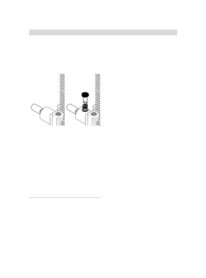
OBJ_BUCH-117-003.book Page 29 Wednesday, June 9, 2010 11:31 AM
Español | 29
Brazo de ajuste
Presione el fijador 16 del brazo de ajuste y manténgalo presionado. Montar hasta el tope el brazo de ajuste 17 a la izquierda o derecha del alojamiento de aparato 8, según necesidad.
Suelte el fijador 16 y asegúrese de la sujeción firme del brazo de ajuste.
1 |
|
|
A |
2 |
A |
|
|
|
|
||
|
|
|
|
|
|
|
|
3 |
|
|
3 |
|
B |
|
|
B |
|
|
|
|
|
||
|
|
|
|
|
A continuación bloquee el recorrido: Tire hacia arriba del bloqueo de recorrido 3 (A), gírelo (B) y suéltelo en esa posición, para enclavarlo c. Si fuese preciso, gire ligeramente el brazo de ajuste 17 hasta conseguir que enclave perceptiblemente.
Solamente desenclave el bloqueo de recorrido al taladrar: Tire hacia arriba del bloqueo de recorrido 3 (A), gírelo (B) y suéltelo en esa posición, para enclavarlo d.
Ruedas de transporte
Para transportar el soporte de taladrar monte las ruedas de transporte 15 con los tornillos de cabeza hexagonal 14 a ambos lados del soporte de taladrar.
Sujeción del soporte de taladrar
Posicionamiento del soporte de taladrar antes de su sujeción
10 |
10 |
GDB 2500 WE |
GDB 1600 WE/DE |
Abatir hacia fuera el indicador de centros 10. Al utilizar el GDB 2500 WE, hacer que coincida la punta del indicador de centros con el centro de la perforación prevista. Si utiliza la
GDB 1600 WE/DE, deberá tomarse como referencia el canto interior del indicador de centros 10.
Al efectuar perforaciones inclinadas, desplazar el soporte de taladrar en la medida m respecto al centro del taladro:
Ángulo de perforación m
m* |
0° |
0 mm |
m** |
15° |
30 mm |
|
30° |
80 mm |
|
45° |
160 mm |
|
m* : GDB 2500 WE |
|
|
m**: GDB 1600 WE/DE |
|
Observación: Sujete firmemente el soporte de taladrar, sin holgura. Con ello se evita que se agarrote y se dañe la corona perforadora.
Dependiendo del tipo y estado del material base, sujete el soporte de taladrar en la posición de perforación prevista con tacos o con la columna de fijación rápida.
Sujete el soporte de taladrar con tacos o con la columna de fijación rápida. Abata hacia dentro el indicador de centros 10.
|
|
Bosch Power Tools |
|
|
1 609 929 W61 | (9.6.10) |
|
|
||
|
|
|
|
|
|
|
|
|
|
|
|
|
|
|
|
|
|
|
|
|
|
|
|
|
|
|
|
|
|
OBJ_BUCH-117-003.book Page 30 Wednesday, June 9, 2010 11:31 AM
30 | Español
Sujeción con tacos (ver figura C)
Para la sujeción del soporte de taladrar con tacos (accesorio especial) en muros de ladrillo u hormigón deberá realizarse un taladro adicional.
Separación del taladro del taco – Centro de la perforación prevista
|
óptima |
posible |
GDB 2500 WE |
330 mm |
310–380 mm |
GDB 1600 WE/DE |
270 mm |
250–320 mm |
En perforaciones inclinadas, amplíe en la medida m la separación entre el agujero del taco y el centro de la perforación prevista (ver “Posicionamiento del soporte de taladrar antes de su sujeción”).
El taladro para el taco deberá tener las siguientes medidas:
|
Diámetro |
Profundidad |
Ladrillo |
20 mm |
85 mm |
Hormigón |
15 mm |
50 mm |
Emplee un taco para hormigón con cuña de expansión, o un taco para mampostería 23. Enrosque el espárrago de fijación rápida 24 en el taco.
Coloque el soporte de taladrar, inserte una arandela, y enrosque la tuerca de mariposa 25. Apriete la tuerca de mariposa después de la nivelación (ver “Nivelación”) con una llave fija (entrecaras 27 mm).
Sujeción con columna de fijación rápida (ver figuras D y E)
El soporte de taladrar puede sujetarse con una columna de fijación rápida Bosch (accesorio especial) aprisionándolo contra el suelo y el techo, o entre dos paredes. El margen de ajuste va desde 1,7 m a 3 m.
Aplique uno de los extremos de la columna contra la placa base del soporte de taladrar. La superficie de asiento de la pared para el otro extremo de la columna, no deberá deberá ser resbaladiza y deberá disponer de una resistencia suficiente.
Para sujetar la columna de fijación rápida lea y respete las indicaciones en las instrucciones de servicio de ésta.
Nivelación
Regular hacia dentro o hacia fuera cada tornillo de nivelación 11 de manera que el nivel de burbuja 4 (en caso de un montaje vertical) o el nivel de burbuja 5 (si el montaje es horizontal) quede exactamente nivelado.
Seguidamente, sujete firmemente el soporte de taladrar empleando el sistema de sujeción por taco, o una columna de fijación rápida.
Operación
fDespués de cada reajuste realizado en el soporte de taladrar vuelva a apretar firmemente las palancas de fijación y observe que enclaven los elementos correspondientes.
Modificación del ángulo de perforación (ver figura F)
Afloje la palanca de fijación superior 21 y la palanca de fijación inferior 22 para el ajuste del ángulo.
Tire del botón de retención 20. Ajuste en el soporte de taladrar uno de los cuatro ángulos de perforación (0°, 15°, 30° o 45°) posibles, y deje enclavar el botón de retención en el rebaje correspondiente de la columna.
Apriete ambas palancas de fijación 21 y 22.
fEl soporte de taladrar solamente deberá emplearse después de haber apretado ambas palancas de fijación para el ajuste del ángulo.
|
|
1 609 929 W61 | (9.6.10) |
|
|
Bosch Power Tools |
|
|
||
|
|
|
|
|
|
|
|
|
|
|
|
|
|
|
|
|
|
|
|
|
|
|
|
|
|
|
|
|
|
 Loading...