


 Loading...
Security Escort
Installation and Setup
Guide
EN Security Escort

EN | 2
Agencies
Consult the documentation accompanying each component for specific listings.
2.0 Equipment Estimation: This section serves as a guide to estimating the equipment needed for a bid, the location accuracy to expect, and how to mount the receivers to achieve that accuracy.
About This Manual
General Information
The purpose of this manual is to identify the components of the Security Escort system, provide installation instructions for those components as well as the system as a whole provide testing procedures for the system and its components, and provide a troubleshooting guide. The sections of this manual are as follows:
•1.0 System Overview: This section provides a reference for estimating and ordering components for a Security Escort installation. Attention is given to relevant specifications of individual components to assist an installer in providing accurate bid estimation.
•
•3.0 Installation Instructions: This section provides an overview and quick reference for the overall installation of a Security Escort System. Consult the Installation Instructions that accompany each individual Security Escort component for specific installation and set-up instructions for that component.
•4.0 System Power-up and Debug: This section includes information on making the system “live” after all components are installed and wired.
•5.0 Testing and Troubleshooting :
This section provides procedures for ensuring that the system is “live” and functional. Also, a troubleshooting guide is provided in the event that some components do not respond to the system.
•
Bosch Security Systems | 1/09 | 33831E
EN | 3
•Appendix: The Appendix provides additional information and forms that may be useful before and during installation.
If you encounter any problems or questions that are not covered in this manual, contact Bosch Security Systems Technical Support at the phone number listed on the back page of this manual.
Safety Symbols and Their Meanings
Throughout this document, the following symbols are used to alert the reader to safety issues when installing or operating the system:
This symbol informs the reader of possible bodily injury if procedures are not followed exactly. The text accompanying this symbol tells the reader what he should or should not do. For example, “ensure that you are properly grounded before opening the unit.”
This symbol alerts the reader to possible equipment damage if procedures are not followed correctly. For example, “do not connect the positive wire to the negative terminal.”
Conflicts with Other Documents
In addition to this manual, the installer is directed to review installation instructions that accompany individual components, and release notes. In the event of a discrepancy between the information provided in this document, and the information provided in a document accompanying a specific component (or release notes), the information contained in the installation instructions or release notes shall prevail.
Trademarks
Microsoft®, Windows, Windows NT®, Windows 98, and Windows 2000 are either registered trademarks or trademarks of Microsoft Corporation in the United States and/or other countries.
Bosch Security Systems | 1/09 | 33831E

Security Escort | Installation and Setup Guide | Table of |
|
EN | 4 |
||||||
Contents |
|
|
|
|
|
|
||
Table of Contents |
|
2.3.2 Indoor Receiver Installation .. 19 |
||||||
|
2.3.3 |
Outdoor Receiver Installation . 19 |
||||||
1.0 |
System Overview |
6 |
||||||
2.4 |
Post Construction Setup |
|
21 |
|||||
1.1 |
System Components Description |
6 |
|
|||||
2.4.1 Testing the location accuracy of |
||||||||
1.2 |
................Compatible Parts |
7 |
2.4.2 |
an installation ............... |
|
21 |
||
1.3 |
System Components and |
8 |
Improving the location accuracy |
23 |
||||
Specifications........................ |
3.0 |
of an installation ............ |
|
|||||
1.3.1 Central Console................. |
8 |
Installation Instructions ..... 25 |
||||||
1.3.2 SE485 Interface Adapter......... |
9 |
3.1 |
Overview of Installation Process |
|||||
...............1.3.3 EA500 Transponder |
9 |
3.2 |
Run..............................System Wiring |
|
25 |
|||
1.3.4 EA102 Receiver................. |
10 |
|
25 |
|||||
1.3.5 EA120 Alert Unit............... |
10 |
3.2.1 |
General Guidelines ............ |
|
25 |
|||
1.4 |
Transmitters................... |
11 |
3.2.2 |
Observe Established Standards . 26 |
||||
1.4.1 |
Personal Escort Transmitters... |
11 |
3.2.3 |
SE485 Interface Wiring Notes .. 30 |
||||
1.4.2 |
SE2 Personal Transmitter....... |
12 |
3.2.4 |
Transponder Wiring Notes ...... |
|
30 |
||
1.4.3 SE3 Subscriber Transmitter Family |
3.2.5 Receiver Wiring Notes ......... |
|
30 |
|||||
|
............................... |
12 |
3.2.6 Alert Unit Wiring Notes |
|
30 |
|||
1.4.4 SE3401 Point Tracking Transmitter |
|
|||||||
3.3 |
Mounting the Enclosures |
|
30 |
|||||
|
|
12 |
|
|||||
|
............................... |
3.3.1 AE1 Small Indoor Enclosure .... 30 |
||||||
1.5 |
Cables |
13 |
||||||
3.3.2 AE3 Large Indoor Enclosure .... 31 |
||||||||
1.5.1 C312: Transponder to ProxLink |
13 |
3.3.3 AE100 Indoor Enclosure |
|
31 |
||||
|
Radio Module Cables |
|
||||||
|
3.3.4 AE101 Outdoor Enclosure |
|
32 |
|||||
1.5.2 Master to Slave |
13 |
|
||||||
3.4 |
Mounting and Setting Up |
|
|
|||||
1.5.3 Computer to SE485 (not supplied) |
Components |
|
32 |
|||||
|
|
13 |
|
|||||
|
............................... |
3.4.1 EA102 Receiver Installation ... 32 |
||||||
1.5.4 Battery Cables |
13 |
|||||||
3.4.2 EA500 Transponder Installation |
32 |
|||||||
1.6 |
Batteries |
13 |
||||||
3.4.3 EA120 Alert Unit Installation . 34 |
||||||||
1.6.1 E28629B, Special 3 Ah |
13 |
|||||||
3.4.4 ProxLink Setup |
|
36 |
||||||
1.6.2 P334, Standard 7 Ah |
14 |
|
||||||
4.0 |
System Power-up and Debug ..... 38 |
|||||||
1.6.3 D1218, Standard 17 Ah.......... |
14 |
|||||||
1.7 |
Enclosures..................... |
14 |
4.1 |
Initial System Configuration .. 38 |
||||
1.7.1 AE1, Small Indoor Enclosure.... |
14 |
4.2 |
Powering Up the System for the |
38 |
||||
1.7.2 AE3, Large Indoor Enclosure |
14 |
First Time .......................... |
|
|||||
5.0 |
Testing and Troubleshooting ... 40 |
|||||||
1.7.3 AE100 Indoor Enclosure |
14 |
|||||||
5.1 |
Built-In Troubleshooting Aids . 40 |
|||||||
........1.7.4 AE101 Outdoor Enclosure |
14 |
5.2 |
Receiver |
|
40 |
|||
1.8 |
Miscellaneous |
14 |
|
|||||
5.2.1 Jumpers |
|
40 |
||||||
1.8.1 Siren Strobe |
14 |
|
||||||
5.2.2 Test Mode |
|
40 |
||||||
1.8.2 TR1850 Transformer, 110 VAC to |
|
|
||||||
|
18 VAC, 50 VA, 60Hz............ |
14 |
.........5.2.3 Receiver Spacing Mode |
|
41 |
|||
1.8.3 E28666B Security Hex Driver.... |
14 |
5.3 |
Transponder ................... |
|
41 |
|||
1.8.4 |
P335-10 Replacement Batteries.. 14 |
5.3.1 Status LEDs ................... |
|
41 |
||||
1.8.5 Holsters for SE2 Transmitters.. 14 |
5.3.2 Verifying Communications ...... |
|
43 |
|||||
1.8.6 SE112.......................... |
15 |
5.4 |
Troubleshooting Reference ..... 43 |
|||||
1.8.7 CTS1-70 Enclosure Cover/Wall |
15 |
Appendix ............................ |
|
47 |
||||
2.0 |
Tamper......................... |
Transponder Information Sheet ....... |
|
47 |
||||
Equipment Estimation........... |
15 |
|
|
|
|
|
||
2.1 |
Location Accuracy.............. |
15 |
|
|
|
|
|
|
2.2 |
Pre-Bid Equipment Estimation... |
16 |
|
|
|
|
|
|
2.2.1 Initial Equipment Estimate..... |
16 |
|
|
|
|
|
||
2.3 Pre-Construction Coverage |
18 |
|
|
|
|
|
||
Verification Survey.................. |
|
|
|
|
|
|||
2.3.1 Verify Each Potential Receiver |
18 |
|
|
|
|
|
||
|
Location....................... |
|
|
|
|
|
||
Bosch Security Systems | 1/09 | 33831E

Security Escort | Installation and Setup Guide | Table of |
EN | 5 |
Contents |
|
Figures
Figure 1: System Block Diagram........ |
6 |
Figure 2: Determining the Number of |
16 |
Indoor Receivers Required... |
Figure 3: Determining the Number of
Outdoor Receivers Required.. 17
Figure 4: Receiver Spacing........... |
18 |
Figure 5: General Wiring Diagram..... |
27 |
Figure 6: Transponder to ProxLink |
28 |
Wiring...................... |
Figure 7: ProxLink to Central Console 29
Figure 8: AE1 Enclosure.............. |
31 |
Figure 9: AE3 Enclosure.............. |
31 |
Figure 10: AE100 Enclosure........... |
31 |
Figure 11: Back of AE100 Enclosure... |
32 |
Figure 12: Inside AE101 Enclosure.... |
32 |
Figure 13: EA500 Mounting to AE1 |
33 |
Enclosure................... |
|
Figure 14: EA500 Mounting to AE3 |
34 |
Enclosure................... |
|
Figure 15: Mounting the EA120 to the |
35 |
AE1 Enclosure............... |
|
Figure 16: Mounting the EA120 in the |
35 |
AE101 Enclosure............. |
|
Figure 17: ProxLink Radio Module |
37 |
Configuration............... |
|
Figure 18: Current Transponder Status |
38 |
Screen...................... |
|
Figure 19: Receiver Configuration |
39 |
Screen...................... |
|
Figure 20: EA500 Diagnostic LEDs..... |
41 |
Figure 21: EA501 Diagnostics LEDs.... |
41 |
Tables
Table 1: Compatible Parts............. |
7 |
Table 2: Models and Supported Users... |
8 |
Table 3: SE2 Personal Transmitter |
12 |
Features.................... |
|
Table 4: SE3 Subscriber Transmitter |
12 |
Features.................... |
|
Table 5: Battery Amp Hours........... |
13 |
Table 6: Wiring Guidelines........... |
25 |
Table 7: Transponder - SE485 Wiring |
26 |
Table....................... |
|
Table 8: Jumper Operation............ |
40 |
Table 9: Status LEDs................. |
42 |
Table 10:Transponder Communications |
43 |
with SE485 Bus.............. |
Table 11:.Transponder Communication with
ProxLink Radio.............. |
43 |
Table 12:EA500 Transponder Bus Faults 45 |
|
Table 13:EA102 Receiver Issues....... |
45 |
Bosch Security Systems | 1/09 | 33831E

Security Escort | Installation and Setup Guide | 1.0 |
EN | 6 |
System Overview |
|
1.0System Overview
1.1System Components Description
The Security Escort System consists of five basic components: transmitters, receivers, alert units, transponders, and the central console.
Figure 1: System Block Diagram |
|
|
|
1 |
2 |
|
|
|
|
|
|
|
|
|
6 |
|
3 |
|
|
|
|
4 |
|
|
|
5 |
|
7 |
2 |
|
|
|
|
|
|
8 |
|
9 |
|
|
|
|
|
|
3 |
|
|
|
|
4 |
|
|
|
10 |
11 |
1 - Personal |
4 - Transponder |
7 - Other transmitter |
10 - Alert unit |
transmitter |
5 - Interface |
types |
11 - |
2 - Outdoor |
6 - Central console |
8 - Security transmitter |
Siren/strobe |
receiver |
|
9 - Spread spectrum |
|
3 - Indoor receiver |
|
wireless link |
|
Transmitter: A miniature, hand-held radio transmitter used to send either a distress or a test signal. The receivers are located throughout the protected area and detect the radio transmissions from transmitters.
Alert units: Siren/strobe units activated in the event of an alarm.
Transponders: Devices that control groups of receivers and alert units, connected to them by wire. Each transponder relays alarm and test signals from its receivers to the central console. In addition, the
Transponder tests for device and wiring faults, and transmits problem conditions to the central console.
Central console: A computer (plus an optional backup and up to eight optional workstations) which receives alarm and trouble signals from the transponders, analyzes the signals, activates strobes and sirens on the alert units, and produces a display for the security dispatcher. Each of these system elements is described more fully in the sections that follow.
Bosch Security Systems | 1/09 | 33831E

Security Escort | Installation and Setup Guide | 1.0 |
EN | 7 |
System Overview |
|
1.2Compatible Parts
Table 1 indicates the parts available for inclusion in a Security Escort System. Contact Bosch Security Systems Customer Service for up-to-date model numbers.
Table 1: Compatible Parts
|
|
|
Part Name |
|
Description |
Electronics, |
EA500 |
Electronics for eight-bus transponder |
Components |
EA102 |
Electronics for indoor or outdoor receiver |
|
EA120 |
Electronics for indoor and outdoor alert unit |
|
SE485 |
Interface between transponder and central console |
|
SE3 |
Personal duress transmitter |
|
Transmitters |
Man-down, lanyard, supervisory, and duress |
|
SE2 |
transmitter |
|
Transmitters |
Point tracking transmitter |
|
SE3401 |
|
Enclosures and |
AE3 |
Housings |
AE1 |
|
AE100 |
|
AE101 |
Large [51.5 cm x 37.5 cm (20.25 in. x 14.75 in.)] enclosure
Small [36.8 cm x 31.8 cm (14.5 in. x 12.5 in.)] enclosure
Indoor receiver enclosure Outdoor receiver enclosure
Cables |
C311 |
3 Ah or 7 Ah battery harness parallel expansion |
kit |
|
C312 |
Cables for transponder to ProxLink Radio Module |
|
Software |
SE2005 |
|
SE2010 |
|
SE2050 |
|
SE2100 |
Misc. Parts and |
HOLST-LGB-SE2 |
Accessories |
HOLSTER-SE2 |
|
E28666B |
|
TR1850 |
P335-10
E28629B
P334
D1218
SE112
CTS1-70
System software for up to 500 users
System software for up to 1000 users
System software for up to 5000 users
System software for up to 10000 users
Leather holster for SE2 Transmitters, large belt loop [5.7 cm (2.25 in.)]
Leather holster for SE2 Transmitters, standard belt loop [4.5 cm (1.75 in.)]
Security hex driver for receivers Transformer
SE2 Replacement Batteries, ten pack of CR2, 3 VDC lithium
3 Ah 12 V battery for outdoor alert unit
7 Ah 12 V battery for indoor alert unit
17 Ah 12 V battery
Portable test receiver with display Enclosure cover/wall tamper for AE1 and AE3
Bosch Security Systems | 1/09 | 33831E

Security Escort | Installation and Setup Guide | 1.0 |
EN | 8 |
System Overview |
|
1.3System Components and Specifications
1.3.1 Central Console Description
The central console consists of one or two IBM PC compatible computers (and up to eight additional workstations) running the Security Escort software
within the Microsoft® Windows® environment. One computer serves as the master controller for the entire Security Escort system. The second slave computer serves as a back-up. The slave computer can be used for administrative functions such as adding subscribers or performing routine system tests without interfering with the operation of the main computer. The workstations can perform all normal Security Escort functions with the exception of communicating with the Security Escort transponders.
Software Overview
The central console contains all the operating software and all the databases required by the Security Escort system. The installation and maintenance portion of the Security Escort software facilitates set-up and modification of the system and provides rapid diagnosis of system problems. Usually only one person is required. The system software also continually monitors the status of each transponder to ensure it functions correctly.
Versions
There are several versions of the software available. The number of users the system supports defines each version. Table 2 lists the available models and the number of supported users:
Table 2: Models and Supported Users
|
|
Model |
User Base |
SE2005 |
500 |
SE2010 |
1000 |
SE2050 |
5000 |
SE2100 |
10000 |
|
|
For systems supporting more than 10000 users, contact Bosch Security System Sales.
Minimum System Requirements
Each computer in the central console should be equipped with at least the following features and components:
•Processor: Pentium class processor or better, 200 MHz or faster.
•Operating system: Microsoft Windows 95, Windows 98, Windows NT® (4.0 or later), or Windows 2000.
•RAM: 16 megabytes of RAM minimum, 32 megabytes preferred, in Windows 95 or Windows 98. Windows NT or Windows 2000 systems should have 64 megabytes of RAM.
•Hard disk space: 1 gigabyte of hard disk space should be available to allow collection of historical data.
•Backup: External backup drive, such as an Iomega or SyQuest Cartridge Hard Disk for backup and history storage.
•Video: VGA (640 x 480) at 256 colors minimum, 800 x 600 high color (16 bits) recommended, 1024 x 768 high color supported, true color (24 bits) is also supported. If displaying subscriber images, high color (16 bits) or true color (24 bits) should be used.
•Modem: Optional V.32 bis (14.4), V.34 (33.8), or V.90 (56.6) modem for remote access and pager dialout. If the modem is external, an additional serial port is required.
•Sound: Any Windows compatible sound system. One set of computer speakers per computer.
•Printer: Parallel port, dot matrix, continuous forms, printer for alarm output.
Note:
Bosch Security Systems | 1/09 | 33831E

Security Escort | Installation and Setup Guide | 1.0 |
EN | 9 |
System Overview |
|
•Additional serial ports (if needed): Any multi-port board fully supported by Windows. A four-port ISA serial port card made by Digiboard, model AccelePort Xe, part number 76000035. Required four-port cable for DB25, part number 76000008. Digiboard also makes eightand sixteen-port solutions. They may be contacted at www.digiboard.com.
Databases
•Alarm reports: Each alarm is saved as a record containing subscriber data, time and date of alarm, acknowledgment and silence times, responding officer, problem description, and action taken. The alarm map can be reproduced and the location text is displayed.
•History: A complete chronological history of all system actions, tests, and alarms is recorded.
•Operators: File of those authorized to use the Security Escort system.
•Subscriber: Complete record of all subscriber data and current status, low battery, and last test date and time.
•Transponders: System configuration containing all installed equipment and system interrelationships.
Other Specifications
•Temperature range: 0ºC to +40ºC (+32ºF to +105ºF)
•Primary power: 120 VAC 900 W (two computers, two monitors, and one printer).
•Backup power: 1200 VA UPS per computer provides 45 min. to 1-hr. backup. System should also be backed up by an emergency generator for extended blackouts (can be shared with other emergency equipment).
•Pager: Pager support is included and selected troubles can be automatically sent to a service pager.
1.3.2 SE485 Interface Adapter Description
The SE485 is an interface between the pseudo RS-485 signal bus of the Security Escort Transponder and the Serial Bus (RS-232) of the Security Escort central console. The SE485 allows multiple transponders to interface into a single RS-232 port.
Due to changes made for transient protection, transformer isolation, and link busy detection, these signals are not compatible with third party RS-485 interfaces.
Specifications
•Dimensions: 13.5 cm x 8.5 cm x 30 cm
(5.375 in. x 3.3125 in. x 1.1875 in.).
•Power Source: 9 VDC, 200 mA. An included 120 VAC adapter to 9 VDC or from the transponder 9 VDC terminals.
•Temperature range: 0°C to +65°C (+32°F to +149°F)
1.3.3 EA500 Transponder Description
The transponder is a device controller for up to 64 devices; and any combination of receivers and alert units. The devices are connected to the transponder by means of four-wire buses; two for power and two for data. There are eight buses and each bus is capable of supporting up to eight devices. The Security Escort system supports up to 255 transponders.
Specifications
•Compatible Enclosures:
-Small indoor: AE1
-Large indoor: AE3 (recommended)
•Temperature range: -40°C to +65°C (-40°F to +149°F)
•Power Source: 18 VAC, 50 VA (can use TR1850, 110 VAC to 18 VAC transformer)
•Battery backup: 12 VDC lead acid battery
Bosch Security Systems | 1/09 | 33831E

Security Escort | Installation and Setup Guide | 1.0 |
EN | 10 |
System Overview |
|
•Power output: 9 VDC output for SE485 or for ProxLink Radio Module power
•Driver outputs:
-Strobe: 500 mA solid state sink, terminal switches to ground in an alarm condition.
-Siren: 500 mA solid state sink, terminal switches to ground in an alarm condition.
•Multiplex buses: eight multiplex driver buses for power and communication to receivers or alert units
•Communication interface to central console: selectable SE485 or RS-232
•Keyswitch input: Optional 47k EOL resistor, supervised loop
1.3.4 EA102 Receiver Description
The EA102 Receivers are located throughout the grounds and building interiors. Each receiver contains a radio receiver to detect the transmissions from transmitters. Multiple receivers detect the same transmission and send the signal information to the transponder so the system can identify the transmitting device, transmitting information, and location. The receiver also reports housing tampering and radio jamming to the transponder.
Indoor receivers are typically mounted on inside walls and have one red and one green LED. The green LED is used to indicate a successful Test of a personal transmitter. The red LED is illuminated during alarms. Each receiver contains a piezo-electric horn that can be activated if the receiver detected an alarm transmission
Outdoor receivers are contained in small weatherproof boxes typically mounted on the sides of buildings and on light posts. Outdoor receivers do not have the visible red and green LED’s. Outdoors, the strobe lights on the alert units should be used to acknowledge successful test and alarm.
Specifications
•Enclosure:
-Indoor: AE100 indoor enclosure
-Outdoor: AE101 outdoor enclosure
•Temperature range: -40°C to +65°C (-40°F to
+149°F)
•Power source: 12 VDC, 25 mA typical, 55 mA with horn sounding, supplied from the transponder MUX bus
•Antenna type: Diversity antennas protected within enclosures
1.3.5 EA120 Alert Unit Description
This is a control module that communicates with the transponder on the MUX Bus. The alert unit can be used to activate strobe and siren units or optional other switched devices. The alert unit also reports tampering, AC power loss, and backup battery level to the transponder.
Specifications
•Enclosures:
-Indoor: AE1 small indoor metal
-Outdoor: AE101 outdoor fiber
•Temperature range: -40°C to +65°C (-40°F to +149°F)
•Power source: 18 VAC, 50 VA (can use TR1850, 110 VAC to 18 VAC transformer)
•Battery backup: 12 VDC lead acid battery
•Driver outputs:
-Power: 1 A maximum, intended as the supply source for strobe and siren
-Strobe: 500 mA solid state sink, terminal switches to ground in an alarm condition
-Siren: 500 mA solid state sink, terminal switches to ground in an alarm condition
Bosch Security Systems | 1/09 | 33831E
Security Escort | Installation and Setup Guide | 1.0 |
EN | 11 |
System Overview |
|
1.4Transmitters
1.4.1 Personal Escort Transmitters
Note:
Not all features are available on
all transmitters.
•Unique ID Code: All Personal Escort Transmitters contain a unique identification that can be entered into the central console System Database. This allows the system to only respond to appropriate users and ignore unauthorized devices. It also allows unique identification of owner in database.
•Local Piezo Sounder: All Personal Escort Transmitters contain an internal piezo sounder device. The piezo is sounded during most types of transmissions to indicate to the user that the alarm or test event was activated.
•Duress Alarm (Manual Alarm): All Personal Escort Transmitters allow an alarm condition to be transmitted by the user manually activating the ALARM buttons.
•Transmitter Test: All Personal Escort Transmitters allow the user to activate the transmitter to perform a system test. This tests that the system acknowledges the transmitter, the receivers in the area function, the transponder communication functions, and the particular transmitter ID are in the central console database.
•Man-Down: Some transmitters contain an internal “tilt” switch that monitors and transmits an alarm if the transmitter is not in an upright position.
•Supervision: Some transmitters send periodic transmissions, allowing the system to monitor activity of the transmitter and report failing transmitters or missing transmitters.
•Note:
Supervision transmissions do not activate the local piezo sounder.
•Lanyard: Some transmitters contain a “pull switch” that transmits an alarm if the lanyard is pulled from the transmitter unit.
•Auto Tracking: When an alarm is transmitted, the transmitter continues to transmit periodically for 15-min. following the alarm. This allows the system to track a moving transmitter that is activated.
•Silent Manual Alarm (“Security”):
This feature is available on Security Transmitters. When the duress alarm (manual alarm) is activated by the user, there is no local sounder turned on. This allows users to transmit the alarm silently.
•Maintenance Transmitter: Used to validate the system functions. By performing a test, the receiver indicates receptions by lighting the green LED. Transmitting an alarm lights the red LED. The Maintenance Transmitters do not activate a real system alarm, the system uses the information for diagnostic and test purposes only. There is no auto tracking on the Maintenance Transmitters.
•Low Battery Indication: The battery status is sent with each transmission, the system tracks and reports low battery devices.
Bosch Security Systems | 1/09 | 33831E

|
Security Escort | Installation and Setup Guide | 1.0 |
EN | 12 |
|
|
System Overview |
|
|
|
1.4.2 SE2 Personal Transmitter |
|
|
|
Description |
|
|
|
There are several versions of the SE2, |
|
|
|
and these versions along with their |
|
|
|
respective features are shown in Table |
|
|
3: |
|
|
|
|
Table 3: SE2 Personal Transmitter Features |
|
|
|
|
|
|
|
|
|
|
Feature |
|
SE2U |
|
SE2S |
|
Manual Duress Alarm |
9 |
9 |
Manual Test |
9 |
9 |
Man-Down |
9 |
9 |
Supervision |
9 |
9 |
Lanyard Snatch |
|
|
Auto Tracking |
9 |
9 |
Silent Manual Alarm |
9 |
|
Low Battery Indication |
9 |
9 |
Note:
Due to communications limitations between the transponder and receivers, a maximum of 200 supervised SE2 transmitters can be handled in a Security Escort system.
Specifications
•Battery: User replaceable 3 V lithium
•Temperature range: -30ºC to +65ºC (-22ºF to +150ºF)
1.4.3SE3 Subscriber Transmitter Family
Description
The SE3 Subscriber Transmitter is a personal duress transmitter that contains the Manual Duress Alarm, Manual Test, and Auto Tracking features.
Table 4: SE3 Subscriber Transmitter
Features
|
|
|
Feature |
|
Model |
|
SE3U |
SE3S |
Manual Duress Alarm |
9 |
9 |
Manual Test |
9 |
9 |
Auto Tracking |
9 |
9 |
Silent Manual Alarm |
|
9 |
Low Battery Indication |
9 |
9 |
|
Model |
|
SE2M |
SE2S-SN |
SE2U-SN |
9 |
9 |
9 |
9 |
9 |
9 |
9 |
9 |
9 |
9 |
9 |
9 |
9 |
9 |
9 |
|
9 |
9 |
|
9 |
|
9 |
9 |
9 |
Specifications
•Battery: Two user replaceable 3 VDC lithium coin cells (CR2025 size)
•Temperature range: (-30ºC to +65ºC) -22ºF to +150ºF
1.4.4SE3401 Point Tracking Transmitter
Description
The SE3401 Point Transmitter is a magnetic and dry contact wireless transmitter used for monitoring assets.
The unit is equipped with an internal reed contact for use with an external magnet assembly (included), a cover tamper switch and RF supervision. The SE3401 also can accept a supervised dry contact input from an external device.
Specifications
•Dimensions:
-Transmitter w/o Mounting Plate: 35 mm x 76.5 mm x 19 mm
(1.5 in. x 3.25 in. x .75 in.)
-Mounting Plate:
35 mm x 76.5 mm x 3.2 mm
(1.5 in. x 3.25 in. x .125 in.)
•Operating Temperature: (-20°C to +65°C )
(-4°F to +150°F)
Bosch Security Systems | 1/09 | 33831E

Security Escort | Installation and Setup Guide | 1.0 |
EN | 13 |
System Overview |
|
•Operating Voltage: Supplied by a 3 VDC lithium battery.
•Battery Life: Up to five years under normal usage with the recommended battery types. Higher usage decreases battery life.
•Recommended Battery Types: Duracell DL123A, Energizer EL123AP, or Panasonic CR123A.
•Compatible Receivers: EA102A-304
•Options: Magnet-RF-10 Assembly (supplied in packages of ten)
1.5Cables
1.5.1C312: Transponder to ProxLink Radio Module Cables
Description
Two cables - one cable provides power from the Transponder to the ProxLink Radio Module; the other cable provides data transfer between the Transponder and ProxLink Radio Module (nonstandard cable).
Specifications
•Power
-Length: 1.8 m (72 in.)
-Connectors: DC power plug at one end (negative contact on outside, positive contact in center), flying leads on the other end
•Data
-Length: 76 cm (30 in.)
-Connectors: Standard male DB9 connectors at each end, wired special for data link. NOT a standard cable.
1.5.2 Master to Slave Note:
This cable is not supplied by Bosch Security Systems.
Description
Null modem cable connecting the two computers running the central console software.
Specifications
•Maximum Length: 15 m (50 ft.)
•Connectors: To be compatible with your PC’s requirements.
1.5.3 Computer to SE485 (not supplied) Note:
This cable is not supplied by Bosch Security Systems.
Description
This cable connects the SE485 Interface to the serial port of the Security Escort central console.
Specifications
•Maximum length: 15 m (50 ft.)
•Connectors: The SE485 uses a DB25 pin male connector, the other end depends on the computer serial port connector. The wiring is a straight-through serial cable.
1.5.4 Battery Cables Description
C311: This kit is used to parallel connect two small-lug-size batteries to increase backup battery capacity.
1.6Batteries
Bosch Security Systems recommends that you supply your own 12 V lead-acid batteries for system component back-up time as needed for your installation. However, some of the standard battery sizes can be supported. See Table 5 for the required amp hours of the batteries for your installation.
Table 5: Battery Amp Hours
Amp hours (Ah) Required per
Number of Receivers
Number |
8 |
16 |
32 |
64 |
of |
|
|
|
|
Hours |
|
|
|
|
4 |
2.3 |
3.5 |
5.7 |
10.2 |
8 |
4.6 |
7.0 |
11.4 |
20.4 |
12 |
7.0 |
10.3 |
17.0 |
30.6 |
24 |
14 |
20.6 |
34.0 |
---- |
1.6.1 E28629B, Special 3 Ah Description
Special size used especially for the outdoor alert unit.
Bosch Security Systems | 1/09 | 33831E

Security Escort | Installation and Setup Guide | 1.0 |
EN | 14 |
System Overview |
|
Specifications
•Dimensions: 6.3 cm x 13.3 cm x 6.3 cm
(2.5 in. x 5.25 in. x 2.5 in.)
•Amp-hours: 3 Ah
•Voltage: 12 VDC
1.6.2 P334, Standard 7 Ah
Specifications
•Dimensions: 9.5 cm x 15.2 cm x 6.3 cm
(3.75 in. x 6 in. x 2.5 in.)
•Amp-hours: 7 Ah
•Voltage: 12 VDC
1.6.3 D1218, Standard 17 Ah
Specifications
•Dimensions: 16.5 cm x 17.8 cm x 7.6 cm
(6 1/2 in. x 7 in. x 3 in.)
•Amp-hours: 17 Ah
•Voltage: 12 VDC
1.7Enclosures
1.7.1 AE1, Small Indoor Enclosure Description
The AE1 Enclosure is suitable only for indoor installation. A mounting kit for the electronic components is included.
Specifications
Dimensions: 36.8 cm x 31.8 cm x 8.6 cm (14.5 in. x 12.5 in. x 3.375 in.)
1.7.2 AE3, Large Indoor Enclosure Description
The AE3 is suitable only for indoor installation. A mounting kit for the electronic components is included.
Specifications
Dimensions: 52.7 cm x 38 cm x 10.8 cm (20.75 in. x 15 in. x 4.25 in.)
1.7.3 AE100 Indoor Enclosure Description
The AE100 Indoor Enclosure houses the receiver. It is suitable only for indoor installation.
Mounting screws: Security design, require E28666B security hex driver
Specifications
Dimensions: 22.9 cm x 17.8 cm x 14.4 cm
(9 in. x 7 in. x 1.75 in.)
1.7.4 AE101 Outdoor Enclosure Description
This enclosure houses the receiver or alert unit. It is suitable for outdoor installation. The receiver’s LEDs and sounder cannot be used in this enclosure. A mounting kit for the electronic components is included.
Specifications
Dimensions: 37.5 cm x 32.4 cm x 8.9 cm (14.75 in. x 12.75 in. x 3.5 in.)
1.8Miscellaneous
1.8.1 Siren Strobe
The armored siren with strobe can be purchased through third-party vendors. Bosch Security Systems recommends Amseco Armored Siren with Strobe (model number SSX-51S).
1.8.2TR1850 Transformer, 110 VAC to 18 VAC, 50 VA, 60Hz
Description
The TR1850 Transformer provides AC power to the transponder and alert unit.
Specifications
•Input: 110 VAC, 60 Hz
•Output: 18 VAC, 50 VA max.
1.8.3 E28666B Security Hex Driver Description
The E28666B Security Hex Driver is the tool required to mount and maintain the indoor receiver enclosures.
1.8.4 P335-10 Replacement Batteries Description
The P335-10 is a ten-pack of lithium replacement batteries for the SE2 Transmitters.
1.8.5 Holsters for SE2 Transmitters Description
•HOLSTER-SE2: Leather holster for 4.4 cm
(1.75 in.) security belt.
•HOLST-LGB-SE2: Leather holster for 5.7 cm
(2.25 in.) security belt.
Bosch Security Systems | 1/09 | 33831E

Security Escort | Installation and Setup Guide | 2.0 |
EN | 15 |
|
Equipment Estimation |
|
|
1.8.6 SE112 |
2.0 Equipment Estimation |
|
Description |
||
Custom Test Receiver with LCD display.
1.8.7CTS1-70 Enclosure Cover/Wall Tamper
Description
The CTS1-70 can be installed in AE1 and AE3 Enclosures for use as a cover tamper switch, a wall tamper switch or both (two required). The CTS1-70 is intended for connection to normally closed tamper or supervised circuits, and operates as a normally closed device when the plunger is depressed.
Specifications
Contacts are rated 0.3 A, 100 VDC, maximum.
A Security Escort system installation consists of three major steps.
1.The pre-bid equipment estimation
2.The pre-construction coverage verification survey
3.The post construction setup
The Security Escort Receivers work effectively in a wide variety of installations and can be placed with confidence provided these installation requirements are met. Therefore, at the pre-bid stage, it is acceptable to estimate the required equipment. To ensure proper coverage after proposal acceptance, potential receiver locations can be verified using a standard receiver in test mode or the portable test receiver before construction begins.
2.1 Location Accuracy
The Security Escort system provides quick response to a duress call by dispatching a responding individual to an area without adding additional delay to their response to that duress call.
The Security Escort system uses radio frequency (RF) for alarm transmissions. This is significant because it prevents normal construction from blocking the signal and helps to eliminate dead spots where the alarm cannot be heard. The fact that RF energy passes through normal construction prevents Security Escort from locating an alarm with 100% certainty to a specific side of a wall. Alarms originating at or near building walls are typically indicated within 7.5 m (25 ft.) of the actual location; however, there may be times when the computed location may appear to be on the other side of the wall.
The Security Escort system was designed to provide a computed alarm location typically within 7.5 m
(25 ft.) of the actual location when indoors and a computed alarm location typically within 15 m (50 ft.) of the actual location outdoors. Any deviation from the following installation guidelines degrades the computed location accuracy. Use the following installation guidelines, to achieve these results.
Bosch Security Systems | 1/09 | 33831E
Security Escort | Installation and Setup Guide | 2.0 |
EN | 16 |
Equipment Estimation |
|
2.2Pre-Bid Equipment Estimation
The pre-bid equipment estimation is performed prior to bidding the installation. At this point, it must be determined what type of coverage is desired, and where the coverage is required. For example, the amount of equipment required for a full-coverage (indoor and outdoor) system in a multi-building application is greater than an installation that requires outdoor only coverage. The customer should be consulted and the areas of most concern should be given special consideration.
2.2.1 Initial Equipment Estimate Number of Indoor Receivers
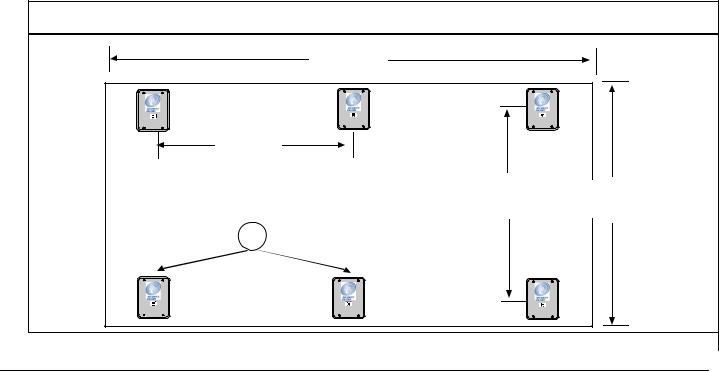
To estimate the number of indoor receivers, first read Section 2.3.2 Indoor Receiver Installation. Assume the receivers are placed on a grid with a maximum spacing of 25 m (80 ft.) between receivers for standard construction. In multi-floor applications the receivers on each floor must be placed directly above the receivers on the floor below (this is required for proper floor-to-floor location).
For example, to determine the number of receivers required to protect a building of standard construction of 60 m x 30 m (200 ft. x 100 ft.) and four floors:
1.To determine the number of receivers in each direction, divide each dimension of the building by 25 m (80 ft.), drop the remainder, and add 1.
For example:
•60 m/25 m = 2.4, becomes 2, add
1 = 3
(200 ft./80 ft. = 2.5, becomes 2, add 1 = 3)
•30 m/25 m =1.2, becomes 1, add 1 = 2
(100 feet/80 feet =1.25, becomes 1, add 1 = 2)
2.To determine the number of receivers required per floor, multiply the number of receivers in one direction by the number of receivers in the other direction: (3 times 2 = 6) 6 receivers per floor
3.To determine the total number of receivers, multiply the number of receivers per floor by the number of floors:
(6 times 4 = 24) 24 receivers for the building
Each floor would require 6 receivers, resulting in a total of 24 receivers to protect this building.
For the best location accuracy, consistent receiver spacing is important. Do not place receivers significantly closer in one section of a building than another section.
Figure 2: Determining the Number of Indoor Receivers Required
60 m
(200 ft.)
25 m
(80 ft.)
25 m |
30 m |
(80 ft.) |
(100 ft.) |
1
1 - Receivers (6)
Bosch Security Systems | 1/09 | 33831E
Security Escort | Installation and Setup Guide | 2.0 |
EN | 17 |
Equipment Estimation |
|
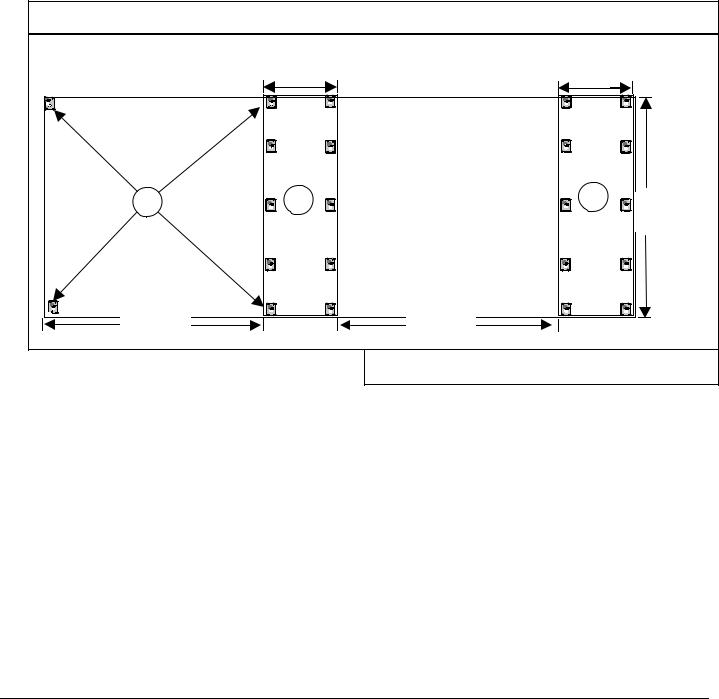
Number of Outdoor Receivers
To estimate the number of receivers, first read Section 2.3.3 Outdoor Receiver Installation. Assume a maximum receiver spacing of 90 m (300 ft.) between receivers, in both directions, for receivers that are not within 30 m (100 ft.) of a building with inside coverage. Receivers within 30 m (100 ft.) of a building should be spaced the same as receivers in the building (spacing the outside receivers at a somewhat larger spacing is acceptable in most cases).
An outside area directly between two buildings with inside protection needs no additional receivers if the buildings are 90 m (300 ft.) or less apart. If the buildings are more than 90 m (300 ft.) apart the outside receivers should evenly spaced between the buildings. Make sure the standard 90 m (300 ft.) spacing is not exceeded. For outside spacing adjacent to a covered building, start the 90 m (300 ft.) spacing at the building wall.
Figure 3: Determining the Number of Outdoor Receivers Required |
|
|||
|
|
30 m |
30 m |
|
|
|
(100 ft.) |
(100 ft.) |
|
|
1 |
2 |
3 |
90 m |
|
|
|
|
(300 ft.) |
|
90 m |
|
90 m |
|
|
(300 ft.) |
|
(300 ft.) |
|
1 |
- Receivers |
|
3 - Building 2 |
|
2 |
- Building 1 |
|
|
|
Allowance for Special Coverage Requirements
For purposes of the bid, the number of receivers estimated should be increased by 5% to allow for special coverage considerations and RF problem areas.
Number of Transponders
Assume one transponder per building for indoor installations. If wiring can be run from other buildings or from outdoor receivers, they can be connected to one transponder. Never exceed the total number of 64 devices (receivers and alert units) per transponder. All outside wiring must be under ground or in metal conduit.
Number of Receiver and Alert Units per Multiplex Bus
Although each bus can handle eight receivers and alert units, it is a good idea to leave some addresses available on each bus to allow for future expansion. For systems with a high number of supervised transmitters, see Section 3.2.4 Transponder Wiring Notes.
Multiplex Bus Wire
The multiplex bus should be wired with four conductor 1.2 mm (18 AWG) wire. The wire should not be paired or shielded. In the United States this is the same as fire system wire, except it should not be red.
Bosch Security Systems | 1/09 | 33831E
Loading...