


SE2000
Table of contents
 Loading...
Security Escort
SE2000 Series
en
Training Manual


Security Escort Table of contents | en 3
Table of contents
1
1.1 What is Security Escort? 7
1.2 Emphasis on reliability 7
1.3 System applications 7
1.4 Some example installations 7
1.5 Other system applications 8
1.6 Security Escort features 8
1.7 System components description 9
1.8 Compatible parts 10
2
2.1 Central Console 11
2.2 SE3 subscriber transmitter 12
2.3 SE2 personnel transmitter 14
2.4 SE3401 asset tracking transmitter 15
2.5 RF3401 asset tracking transmitter 16
2.6 SE88 panic transmitter 16
2.7 SEFD1 transmitter 18
2.8 EA102 receiver 18
2.9 EA500 transponder 19
2.10 EA120 alert unit 20
3
3.1 Location accuracy 22
3.2 Pre-bid equipment estimation 23
3.2.1 Initial equipment estimate 23
3.3 Pre-construction coverage verification survey 25
3.3.1 Verify each potential receiver location 25
3.3.2 Indoor receiver installation 26
3.3.3 Outdoor receiver installation 27
4
4.1 General guidelines 29
4.1.1 Transponder - SE485 wiring table 29
4.1.2 Observe established standards 30
4.2 Component wiring guidelines 30
4.2.1 General wiring diagram 30
4.2.2 Transponder information sheet 32
4.3 EA500 transponder 35
4.3.1 General 35
4.3.2 Specifications 35
4.3.3 Mounting 35
4.3.4 Wiring 35
4.3.5 Set the address 36
4.4 EA102A-304 receiver 37
4.4.1 Specifications 37
4.4.2 Mounting 38
4.4.3 Wiring 39
4.4.4 Switches and jumpers 39
4.4.5 Pre-wired installations 41
4.4.6 Drilling templates 42
System overview 7
System components/specifications 11
Equipment estimation, location accuracy and receiver location 22
System wiring 29
Robert Bosch (SEA) Pte Ltd Training Manual 2017.08 | V2.18.1.0 | DOC

4 en | Table of contents Security Escort
4.5 EA120B alert unit 43
4.5.1 Specifications 43
4.5.2 General information 44
4.5.3 Mounting 44
4.5.4 Wiring 45
4.5.5 Set the address 45
4.6 Moxa interface 45
4.6.1 Introduction 45
4.6.2 Specifications 45
4.6.3 Installation and operation notes 46
4.7 Lantronix interface 48
4.7.1 Introduction 48
4.7.2 Specifications 48
4.7.3 Installation and operation notes 48
4.8 SE485 interface 52
4.8.1 Introduction 52
4.8.2 Specifications 52
4.8.3 Installation and operation notes 52
4.9 ProxLink setup 53
5
Installation options 57
5.1 Demo installations 57
5.2 Non-network installations 57
5.3 Network installations 57
5.4 Installing the Security Escort software 58
5.4.1 Software installation procedure 58
5.4.2 Image files 66
6
Central Console, computer setup and programming 68
6.1 Transponder comm port setup 68
6.2 Remote comm port setup dialog 68
6.3 Remote setup dialog 70
6.4 Transponder Database 73
6.4.1 Transponder information sheet 74
6.4.2 Transponder Database dialog 77
6.4.3 Creating a new transponder entry 80
6.4.4 Modifying existing transponder entry 81
6.4.5 Setting receiver parameters 82
6.4.6 Alarm area setup 88
6.5 Powering up the system for the first time 89
7
Troubleshooting transponders, points, receivers, and alert units 93
7.1 Common errors 93
7.2 Built-in troubleshooting aids 93
7.2.1 Receiver 93
7.2.2 Transponder 95
7.3 Troubleshooting reference 97
7.3.1 Transponder communication with SE485 bus 97
7.3.2 Transponder communication with ProxLink 99
7.3.3 Transponder communication with Moxa/Lantronix device 101
7.3.4 EA500 transponder bus faults 102
7.3.5 EA102 receiver issues 103
2017.08 | V2.18.1.0 | DOC Training Manual Robert Bosch (SEA) Pte Ltd

Security Escort Table of contents | en 5
7.4 Receiver configuration dialog 106
7.5 Post construction setup 109
7.5.1 Testing the location accuracy of an installation 109
7.5.2 Improving the location accuracy of an installation 111
7.6 System preferences dialog 112
7.7 Security Preferences dialog 118
7.8 System Defaults dialog 122
7.9 System Labels dialog 123
7.10 Subscriber Database 124
7.10.1 Print Subscriber Database 125
7.10.2 Edit Subscriber Database record 126
7.10.3 Additional subscriber information 130
7.10.4 Subscriber images 131
7.10.5 Subscriber Database Advanced Features 131
7.10.6 Subscriber (individual) Pager Setup 136
7.10.7 Fixed Location Transmitters 138
7.11 Schedules dialog 138
7.11.1 Ignore Holidays for this schedule 140
7.11.2 Edit Schedule Times dialog 140
7.11.3 View Alarm Groups dialog 141
7.11.4 Alarm Groups dialog 142
7.11.5 Alarm Group State dialog 143
7.11.6 Current Check-in Status dialog 144
7.12 Exporting, importing and merging the Subscriber Database 145
7.12.1 ".dat" file format 146
7.12.2 Exporting the Subscriber Database 151
7.12.3 Importing the Subscriber Database 152
7.12.4 Merging the Subscriber Database 153
7.13 Exporting and importing the Transponder Database 155
7.13.1 ".dat" file format 155
7.13.2 XML file format 163
7.13.3 Exporting the Transponder Database 168
7.13.4 Importing the Transponder Database 169
7.14 Operator Database 170
7.14.1 Edit Operator Database record 171
7.14.2 Authority levels 172
7.15 Reports Database 173
7.15.1 Report statistics 174
7.15.2 Map 175
7.15.3 Edit data 175
7.15.4 Delete 176
7.15.5 Locate Key 176
7.15.6 Key Select 177
7.15.7 Incomplete 177
7.16 System redundancy 177
7.16.1 Automatic redundancy 178
7.16.2 Manual redundancy 178
8
System menus and dialogs 179
8.1 File menu 179
Robert Bosch (SEA) Pte Ltd Training Manual 2017.08 | V2.18.1.0 | DOC

6 en | Table of contents Security Escort
8.1.1 Locate transmitters 179
8.1.2 Maintenance alarm database 179
8.1.3 Transmitter Change 180
8.2 Utilities menu 183
8.2.1 Backup 183
8.2.2 Restore 185
8.2.3 Print/Export System Reports 187
8.2.4 Export Alarm Reports 189
8.2.5 Alarm Flash Reports 190
8.2.6 Muster Reports 192
8.2.7 Clear screen 194
8.2.8 Output verification 194
8.2.9 Synchronize system time 194
8.3 Setup commands 195
8.3.1 Show history 195
8.3.2 History filter 196
8.3.3 Popup trouble filter 199
8.3.4 Transponder parameter change 204
8.3.5 Transponder data view 206
8.3.6 Receiver configuration 207
8.3.7 Receiver test 211
8.3.8 Network status 213
8.3.9 System status 215
8.3.10 Pager setup 216
8.3.11 Send pager message 218
8.3.12 Email Setup 219
8.4 Print history screen 222
8.4.1 Print file dialog 222
8.5 Network menu 223
8.5.1 System Directories and Network Address Dialog 223
8.5.2 Network Socket Status Dialog 226
8.6 About menu 228
8.6.1 About dialog 229
9
10
Files required for Security Escort 232
Appendix: Software licenses 237
10.1 Bosch software 237
10.2 Other licenses — copyright notices 237
10.3 Warranties and disclaimer of warranties 237
Index 238
2017.08 | V2.18.1.0 | DOC Training Manual Robert Bosch (SEA) Pte Ltd

Security Escort System overview | en 7
1 System overview
1.1 What is Security Escort?
– Unique multiple user help call and asset tracking system
– Identifies user information and location, by floor, above or below ground
– Small, easy to carry transmitters
– Indoor/outdoor protection for 60,000+ users and assets as well as multiple buildings
– Man-down alarm, officer tracking & guard tour
– Post-alarm tracking and alarm map recall
– System capabilities perfect for campus and community environments
1.2 Emphasis on reliability
– Supported by a multi million dollar company
– Extensive field testing under maximum abuse conditions, from -20°F to +120°F
– Supervised system communication
– Low battery user and system operator notification
– Archived retrieval of system activity
– Patented technology
– Post alarm transmitter tracking
– System-wide backup power feature
1.3 System applications
– Student Safety
– Officer Tracking
– Guard Tour
– Employee/Faculty Security
– VIP Protection
– Executive Protection
– Man-Down
– Asset Tracking
1.4 Some example installations
Educational Facilities:
– Florida Southern, FL
– Oswego State, NY
– Nazareth College, NY
Healthcare Facilities:
– New Hanover Medical Center, NC
– Provo Psychiatric Hospital, Utah
– Fairport Retirement Home, NY
Correctional Facilities:
– Westchester County D.O.C., Valhalla, NY
– Immigration & Naturalization Facility, TX
– US Naval Brig, SC
Other:
– Diamond Mines, South Africa
– Amusement Park, FL
– International Art Museum, NY
Robert Bosch (SEA) Pte Ltd Training Manual 2017.08 | V2.18.1.0 | DOC

8 en | System overview Security Escort
1.5 Other system applications
– Hotels & Casinos
– Amusement Parks
– Commercial Complexes
– Buildings
– Parking Lots/Garages
– Museums
– Financial Institutions
– Child Care Facilities
1.6 Security Escort features
The Security Escort System is engineered to provide reliability and user ease of operation. Our
patented feature set allows for customization and integration in any installation. These
features ensure system integrity and the comfort that when assistance is needed, help is just a
click away.
User Self Test
– Assures you that your transmitter is working
– Battery condition sent with every transmission
– Each test verifies system integrity
– Logs each test performed for easy access and reporting
– Can be performed indoors and outdoors
– Ensures user acceptance and peace of mind
Asset Tracking
– Location of assets
– Protection against removal
– Wireless sensing
– No re-cabling for asset relocation
– Auto tracking and location identification
Fixed Point Identification
– Allows for identification of any fixed point
– Simple system integration
– Expands over all system capability and functionality
2017.08 | V2.18.1.0 | DOC Training Manual Robert Bosch (SEA) Pte Ltd
Security Escort System overview | en 9
1.7 System components description
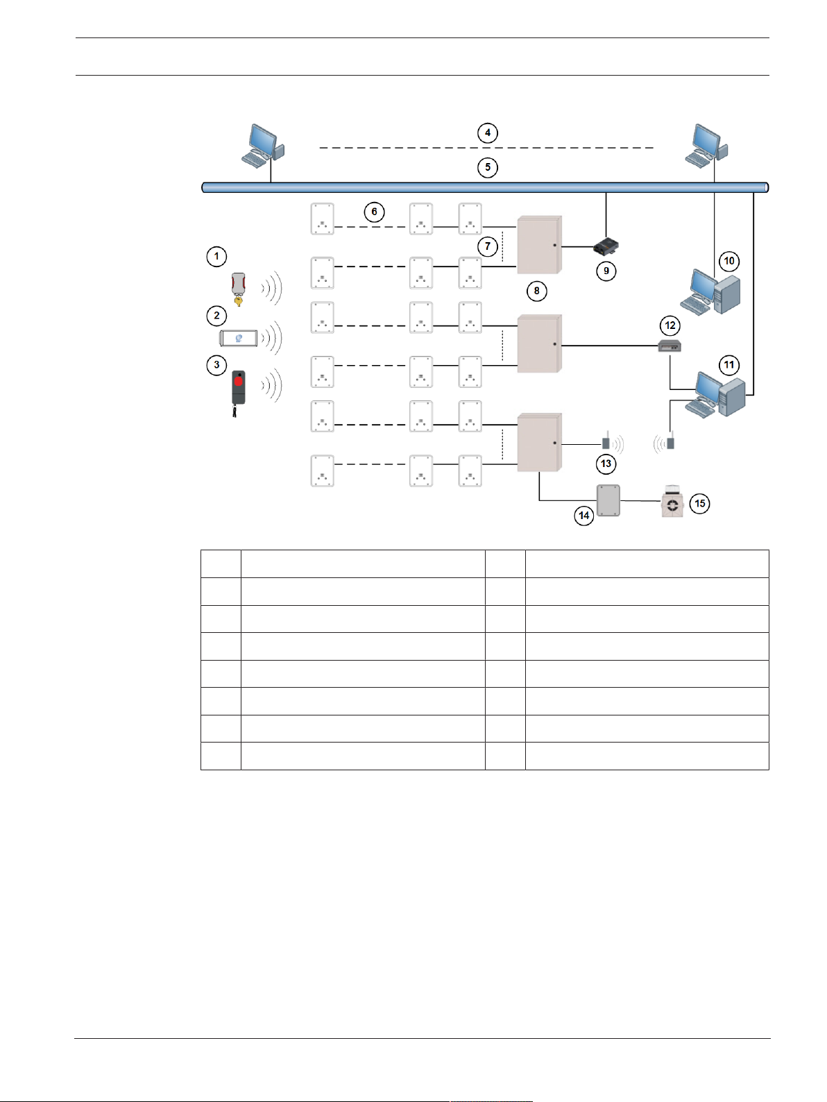
Figure1.1: System Block Diagram
1 Subscriber transmitter 9 Serial to Ethernet interface
2 Point tracking transmitter 10 Slave workstation
3 Personnel transmitter 11 Master workstation
4 Up to 8 workstation 12 SE485 interface
5 LAN 13 Spread spectrum wireless links
6 Up to 8 receivers 14 Alert unit
7 Up to 8 bus 15 Strobe
8 Transponder
The transmitter is a miniature, hand-held radio transmitter used to transmit either a distress
or a test signal. The receivers are located throughout the protected area and detect the radio
transmissions from transmitters. Alert units are siren/strobe units activated in the event of an
alarm. Transponders are devices that control groups of receivers and alert units, connected to
them by wire. Each transponder relays alarm and test signals from its receivers to the Central
Console. In addition, the transponder tests for device and wiring faults, and transmits problem
conditions to the Central Console. The Central Console consists of a computer (plus an
optional backup and up to 8 optional workstations) which receives alarm and trouble signals
from the transponders, analyzes the signals, activates strobes and sirens on the alert units,
and produces a display for the Security dispatcher. Each of these system elements is
described more fully in the sections that follow.
Robert Bosch (SEA) Pte Ltd Training Manual 2017.08 | V2.18.1.0 | DOC

10 en | System overview Security Escort
1.8 Compatible parts
The following table indicates the parts available for inclusion in a Security Escort system.
Contact Bosch Security Systems Customer Service for up-to-date model numbers.
Part Name Description
Electronics, Components
EA500 Electronics for eight-bus transponder
EA102 Electronics for indoor or outdoor receiver
EA120 Electronics for indoor and outdoor alert unit
SE485 Interface between transponder and Central Console
SE2 transmitters Man-down, lanyard, supervisory, and duress transmitter
SE3401 Point tracking transmitter
SE88 Personal watch/Pendant transmitter
Enclosures and Housings
AE3 Large enclosure, 51.5 cm x 37.5 cm (20.25 in x 14.75 in)
AE1 Small enclosure, 36.8 cm x 31.8 cm (14.5 in x 12.5 in]
AE100 Indoor receiver enclosure
AE101 Outdoor receiver enclosure
Software
SE2005 System software for up to 500 users
SE2010 System software for up to 1,000 users
SE2050 System software for up to 5,000 users
2017.08 | V2.18.1.0 | DOC Training Manual Robert Bosch (SEA) Pte Ltd
Security Escort System components/specifications | en 11
2 System components/specifications
2.1 Central Console
Description
The Central Console consists of one or two computers (and up to 8 additional workstations)
running the Security Escort software within the Microsoft Windows environment. One
computer serves as the master controller for the entire Security Escort system and the second
slave computer serves as a back-up. The slave computer can be used for administrative
functions such as adding subscribers or performing routine system tests without interfering
with the operation of the main computer. The workstations can perform all normal Security
Escort functions with the exception of communicating with the transponders.
Software overview
The Central Console contains all of the operating software and all of the databases required
by the Security Escort system. The installation and maintenance portion of the Security Escort
software is designed to facilitate set-up and modification of the system and to provide rapid
diagnosis of system problems, usually with only one person being required. The system
software also continually monitors the status of each transponder to ensure it is functioning
correctly.
Versions
There are several versions of the software available. The number of users the system will
support defines each version. The following table lists the available models and the number of
supported users:
Model User Base
SE2005 500
SE2010 1,000
SE2050 5,000
Notice!
For systems supporting more than 5,000 users contact Bosch Security Systems Sales.
Minimum system requirements
As a minimum, each computer in the Central Console should be equipped with the following
features and components:
– Processor: 1 GHz or faster.
– Operating system: Microsoft Windows XP®, Windows 7® 32/64-bit, Windows 8/8.1® 32/64-
bit, Windows 10® 32/64-bit
– RAM: Minimum 2 GB, due to .NET requirement
– Hard disk space: 1 GB of hard disk space should be available to allow collection of
historical data
– Backup: External backup drive for backup and history storage.
– Video: VGA (640 x 480) at 256 colors minimum, 800 x 600 High color (16 bits)
recommended, 1024 x 768 High color supported. True color (24 bits) is also supported. If
displaying subscriber images, High color (16 bits) or True color (24 bits) should be used.
Robert Bosch (SEA) Pte Ltd Training Manual 2017.08 | V2.18.1.0 | DOC

12 en | System components/specifications Security Escort
– Modem: Optional V.32bis (14.4), V.34 (33.8), or V.90 (56.6) modem for remote access
and pager dial-out. If modem is external an additional serial port is required.
– Sound: Any Windows compatible sound system. One set of computer speakers per
computer.
– Printer: Parallel or network printers.
– Additional serial ports (if needed): Any multi-port board fully supported by Windows. A
four-port ISA serial port card made by Digiboard, model AccelePort Xe, part number
76000035. Required four-port cable for DB25, part number 76000008. Digiboard also
makes eight- and sixteen-port solutions. They may be contacted at www.digiboard.com.
Databases
– Alarm reports: Each alarm is saved as a record containing subscriber data, time and date
of alarm, acknowledgment and silence times, responding officer, problem description,
and action taken. The alarm map can be reproduced and the location text is displayed.
– History: A complete chronological history of all system actions, tests, and alarms is
recorded.
– Operators: File of those authorized to use the Security Escort system.
– Subscriber: Complete record of all subscriber data and current status, low battery, and
last test date and time.
– Transponders: System configuration containing all installed equipment and system
interrelationships.
Other Specifications
– Temperature range: 0 ºC to +40 ºC (+32 ºF to +105 ºF)
– Primary power: 120 V AC 900 W (two computers, two monitors and one printer).
– Backup power: 1200 V A UPS per computer will provide 45 minutes to one hour backup.
System should also be backed up by an emergency generator for extended blackouts (can
be shared with other emergency equipment).
– Pager: Pager support is included and selected troubles can be automatically sent to a
service pager.
2.2 SE3 subscriber transmitter
Features
– Alerts Central Console of user’s name and location immediately on alarm.
– Post-alarm tracking, alarm map recall, and more.
– Allows user to test from anywhere within the protected area.
– Internal antenna.
– Four-year battery life, field replaceable.
– Key-chain attachment.
– Low battery indication at Central Console.
– Optional silent alarm.
2017.08 | V2.18.1.0 | DOC Training Manual Robert Bosch (SEA) Pte Ltd

Security Escort System components/specifications | en 13
Description
The SE3 subscriber transmitter contains a unique code which is associated with the
subscriber at the time the transmitter is assigned. When the subscriber generates an alarm,
this code is sent to the Central Console. The Central Console graphically displays the
subscriber’s location on a map along with the subscriber’s picture, his or her name, and
address.
Transmitting an alarm
In the event of an emergency, the user simply presses and holds the alarm buttons to produce
an alarm. Depending on the installed options, when an alarm is generated within
approximately two seconds, the sounders in any nearby receivers will be activated as well as
the strobes and sirens connected to nearby alert units. The alarm signal is transmitted to the
receivers which in turn relay the alarm signal to the transponder and along to the Central
Console. The Central Console then graphically displays the subscriber’s location along with
the subscriber’s name, vital information (such as a medical condition or disability) and a
picture of the subscriber. Also, once an alarm is initiated, the transmitter commences its autotracking feature.
Auto-tracking
During an alarm, the transmitter automatically resends the alarm signal every few seconds,
constantly updating the Central Console of the subscriber’s location.
Testing
The test mode allows a subscriber to test their transmitter anywhere in the protected area.
When the user is indoors in sight of an indoor receiver, or outdoors in sight of a strobe,
pressing the buttons in sequence performs a test. If the test is successful, a small green light
will flash on the indoor receiver, or the strobe will flash briefly. There will be no response at
all if the test fails. If the test fails, the user should contact the Security office as soon as
possible.
Every successful test is recorded in the Subscriber Database in the Central Console software
and optionally printed on the hardcopy printer. The Subscriber Database contains all of the
information relating to each subscriber, including the date and time of the most recent test
transmission. It is possible to search the Subscriber Database for individuals who have not
performed tests for a specified period of time.
Low battery reporting
When the transmitter is tested, a special “low battery” message is included in the
transmission to the Central Console if the transmitter’s battery is in need of replacing. Also,
the system will not give a visual or audible response during a test, indicating that the
transmitter requires service. Low battery alerts are logged at the Central Console.
Available models
There are two SE3 models available:
– User transmitter: This is the standard transmitter used by all system subscribers.
– Security transmitter: This is the same as the standard transmitter except the transmitter
does not emit an audible tone when activated. This transmitter is normally distributed to
Security personnel.
Robert Bosch (SEA) Pte Ltd Training Manual 2017.08 | V2.18.1.0 | DOC

14 en | System components/specifications Security Escort
2.3 SE2 personnel transmitter
Features
– Personal duress alarm transmitter.
– Man-down alarm.
– Lanyard pull alarm (optional).
– Allows user to test from anywhere within the protected area.
– Notifies Central Console of user’s name and location immediately on alarm.
– Post-alarm and supervision tracking, alarm map recall, and more.
– Internal antenna.
– User replaceable battery with four-year life.
– Belt clip attachment.
– Optional silent manual alarm.
– Low battery indication.
– Optional holster for common security belt sizes.
Description
The SE2 personnel transmitter contains a unique code which is associated with the user at the
time the transmitter is assigned. When the user generates an alarm, this code is sent to the
Central Console. The Central Console graphically displays the user’s location on a map along
with the user’s picture, and his or her name, and any other necessary information.
Transmitting an alarm
There are three ways in which an alarm may be generated, depending on the features enabled
on the transmitter. The types of alarms are as follows:
– Manual duress alarm: An alarm can be initiated by pressing the large button on the
transmitter.
– Man-down alarm: The transmitter will transmit an alarm to the Central Console if it is
tipped 60° from upright.
– Lanyard pull: A cord connected to the pin inserted in the base of the transmitter can be
looped around a utility belt and if the pin is removed from the transmitter (such as when
the transmitter is pulled away from the belt), the transmitter will immediately go into
alarm.
Auto-tracking feature
During an alarm, the transmitter automatically resends the alarm signal every few seconds
constantly updating the Central Console of the user’s location.
Supervision tracking
With supervision tracking enabled, the transmitter will send a tracking signal to the Central
Console constantly updating the user’s location.
Testing
The test mode allows a user to test their transmitter anywhere in the protected area. When
the user is indoors, in sight of an indoor receiver, or outdoors, in sight of a strobe, pressing
the manual test button performs a test. If the test is successful, a small green light will flash
on the indoor receiver, or the strobe will flash briefly. There will be no response at all if the
test fails. If the test fails, the user should contact the Security office as soon as possible.
2017.08 | V2.18.1.0 | DOC Training Manual Robert Bosch (SEA) Pte Ltd

Security Escort System components/specifications | en 15
When the transmitter is tested, a special “low battery” message is included in the
transmission to Central Console if the transmitter’s battery is in need of replacing. Every
successful test is recorded in the Subscriber Database in the Central Console software and
optionally printed on the hardcopy printer. The Subscriber Database contains all of the
information relating to each subscriber, including the date and time of the most recent test
transmission. It is possible to search the Subscriber Database for individuals who have not
performed tests for a specified period of time.
2.4 SE3401 asset tracking transmitter
Features
– Alerts Central Console of Transmitter’s ID and location immediately on alarm.
– Available post-alarm tracking, alarm map recall, and more.
– Internal antenna.
– Two-year battery life.
– Can be mounted virtually anywhere on virtually anything.
– Low battery indication at Central Console.
– Includes mounting plate.
Description
The SE3401 Point Tracking Transmitter contains a unique code which is associated with an
asset at the time the Transmitter is assigned. When an alarm is generated, this code is sent to
the Central Console, which graphically displays the asset’s location on a map along with a
picture of the asset and any other necessary information.
Installation
The SE3401 can be configured to monitor magnetic or dry external contacts. When mounted
with an external magnet, the SE3401 is mounted on the asset and the magnet is mounted on
an opposite surface (such as a wall). When mounted with external contacts, the SE3401 can
be mounted anywhere on the asset and connects to the contact by two wires connected to
the terminals inside the Transmitter and an end-of-line resistor.
Transmitting an Alarm
Depending on the installed options, when an alarm is generated within approximately two
seconds, the sounders in any nearby Receivers could be activated as well as the Strobes and
Sirens connected to nearby Alert Units. The alarm signal is transmitted to the Receivers which
in turn relay the alarm signal to the Transponder and along to the Central Console. The Central
Console graphically displays the Transmitter’s location along with the asset’s description and
a picture of the asset. Also, once an alarm is initiated, the Transmitter commences its AutoTracking feature.
Auto Tracking Feature
Once an alarm has been initiated (such as when the Transmitter has been moved away from
the magnet) the Auto-Tracking feature will begin. The Transmitter will send a signal back to
the Central Console every few seconds updating its location for several minutes. To reset the
Transmitter after an alarm has been initiated, all device conditions (e.g., tamper, loop,
magnet) must be reset to normal.
Robert Bosch (SEA) Pte Ltd Training Manual 2017.08 | V2.18.1.0 | DOC
16 en | System components/specifications Security Escort
Supervision Feature
The SE3401 Point Tracking Transmitter can also be configured to transmit periodically when
there is no other activity to report its status and location to the Central Console.
Low Battery Reporting
When the Transmitter is tested, a special “low battery” message is included in the
transmission to the Central Console if the Transmitter’s battery is in need of replacing. These
low battery alerts are logged at the Central Console.
2.5 RF3401 asset tracking transmitter
Features
– Supervised Sensor Loop (monitors any dry contact device)
– Internal Reed Switch (used with magnet)
– Supervisory Signal Every 65 Minutes
– Complete Status, including Battery and Tamper Sent with Every Transmission
– Compatible with all DS RF-TechTM Receivers @304 MHz
– Factory Programmed Transmitter ID for Quick and Simple Transmitter Enrollment
– Installer (or user) Replaceable Lithium Battery
– Quick Install Mounting Base Plate Included
– Cover Tamper
Description
The RF3401 Point Transmitter features a supervised sensor loop and a magnetic reed switch.
Use the supervised sensor loop to monitor any device with a dry contact output. When used
with an external magnet assembly the RF3401 reed switch allows for quick and easy
installation on doors and windows.
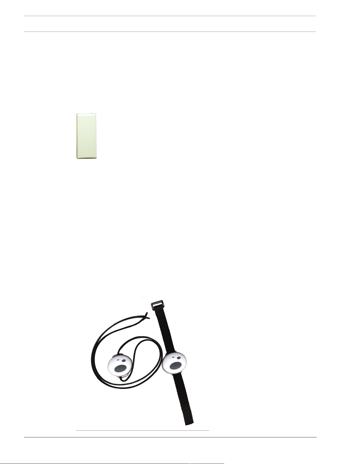
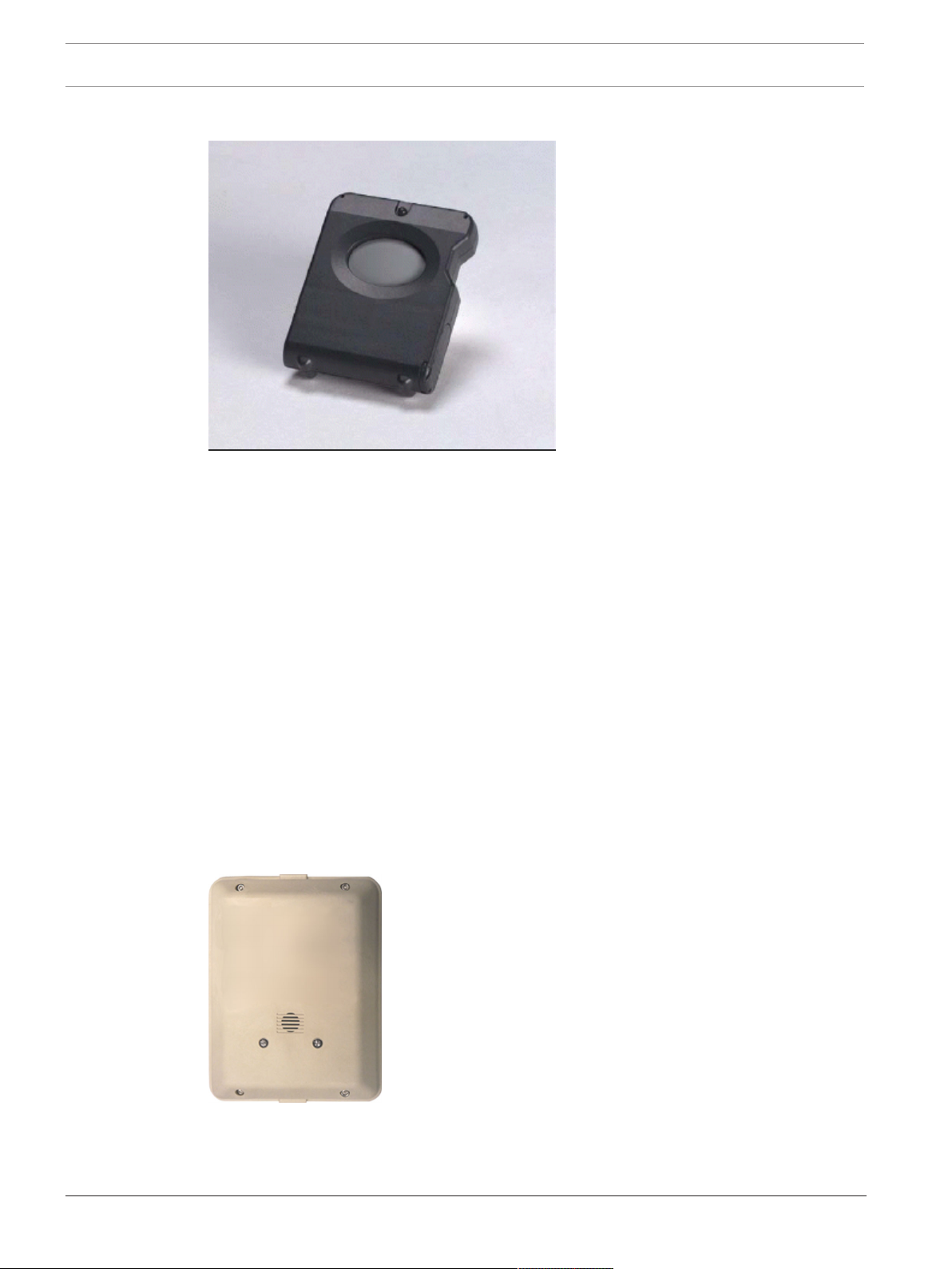
2.6 SE88 panic transmitter
2017.08 | V2.18.1.0 | DOC Training Manual Robert Bosch (SEA) Pte Ltd

Security Escort System components/specifications | en 17
Features
– Can be worn like a watch, pendant or mounted to a permanent location
– Once activated, sends immediate notification of wearer's identity and location
– Water resistant
Description
The SE88 Security Escort Watch/Pendant Panic Transmitter is designed to work with the
Security Escort System. Once activated, the wearer's identity and location is sent to the
security office. The SE88 may be worn like a watch, around the neck like a pendant or even
mounted to a stationary location with a mounting bracket (optional accessories, please order
separately). It is ideal for use in elder care or assisted living facilities where immediate
emergency notification is required.
Transmitting an Alarm
– In the event of an emergency, the user simply presses and holds the alarm buttons to
produce an alarm. Transmittal will vary with different options. Generally, within two
seconds of an alarm being generated, sounders in Receivers and Strobes or Sirens
connected to Alert Units will activate.
– The alarm signal transmits to the Receivers. The Receivers relay the alarm signal to the
Transponder and to the Central Console.
– The Central Console displays the user’s location, picture, name, and vital information
(such as a medical condition or disability).
Auto-Tracking Feature
– During an alarm, the Transmitter automatically resends the alarm signal every few
seconds constantly updating the Central Console of the user’s location.
Testing
– The Test Mode allows a user to test his or her Transmitter anywhere in the protected
area. When the user is indoors in sight of an Indoor Receiver, or outdoors in sight of a
Strobe, pressing the buttons in sequence performs a test. If the test is successful, a small
green light will flash on the indoor Receiver, or the Strobe will flash briefly. There will be
no response at all if the test fails. If the test fails, the user should contact the Security
Office as soon as possible.
– Every successful test is recorded in the Subscriber Database in the Central Console
Software and optionally printed on the hardcopy printer. The Subscriber Database
contains all of the information relating to each subscriber, including the date and time of
the most recent test transmission. It is possible to search the Subscriber Database for
individuals who have not performed tests for a specified period of time.
Low Battery Reporting
– When the Transmitter is tested, a special “low battery” message is included in the
transmission to Central Console if the Transmitter’s battery is in need of replacing. Also,
the system will not give a visual or audible response during a test, indicating that the
Transmitter requires service. Low battery alerts are logged at the Central Console.
Robert Bosch (SEA) Pte Ltd Training Manual 2017.08 | V2.18.1.0 | DOC
18 en | System components/specifications Security Escort
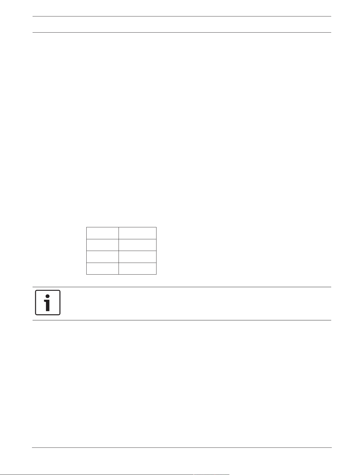
2.7 SEFD1 transmitter
Calls for Help Even When You CannotCalls for Help Even When You Cannot
The SEFD1 Fall Detector and Personal Help Button provides assistance that no other personal
Help Button can offer. The device alerts your emergency monitoring service automatically when
it detects a fall, even if you are unable to push the Help Button on the device.
The SEFD1 is designed to work in and immediately around your home or facility. The device
must be close enough to a receiver for a help signal to be received. The coverage area of the
device will vary from one location to another. It is important for you to know the effective
range of your device.
The SEFD1 is designed to detect falls that meet certain criteria. It may not detect every fall,
especially slight falls that are generally not disabling. The SEFD1 Fall Detector device may also
generate a fall alarm when you have not fallen. For example, if the device drops on the floor, it
may alert the monitoring center that you have fallen.
Operation
The SEFD1 device transmits three conditions:
– Push Button (Help Button)
– Fall
– Low Battery
2.8 EA102 receiver
Features
– Receives Transmitter alarms and tests, and relays the information to the Transponder.
– Built-in self testing through Buddy Check feature.
– Indoor and outdoor security enclosures available.
2017.08 | V2.18.1.0 | DOC Training Manual Robert Bosch (SEA) Pte Ltd
Security Escort System components/specifications | en 19
– Indoor enclosure provides confirmation of successful Transmitter test. (Outdoor
enclosures use other type of signaling device, such as a Horn/Strobe.)
– Indoor Receivers provide local sounders in alarm events.
Description
The Receivers are located throughout the protected area, including building interiors.
Each Receiver contains a radio receiver to detect the transmissions from Transmitters, and a
microcomputer to decode and interpret the received test and alarm messages. In addition, the
microcomputer monitors tampering and other problems, and reports such conditions to the
Transponder.
Each Receiver contains an internal self-contained sounder. These sounders are optionally
activated if the Receiver has detected an alarm transmission.
Indoor Receivers are typically mounted on inside walls and are housed in small beige,
rectangular units. Indoor Receivers have one red and one green light. The green light is used
to indicate a successful test of a Transmitter; the red light is only illuminated during certain
system tests and during alarms.
Outdoor Receivers are contained in small weatherproof enclosures typically mounted on the
sides of buildings and on light posts. Outdoor Receivers do not have the visible red and green
LED’s. Outdoors, the strobe lights connected to the Alert Units flash to acknowledge a
successful test.
Function During an Alarm
In the event of an alarm, the Receivers detect an alarm signal from a Transmitter and send this
information to the Transponder. The Transponder forwards this information the Central
Console where, using the reported information from all the Receivers that detected the signal,
the location of the transmission is graphically displayed on the Alarm Map.
Buddy Check
In addition to its radio receiver, each Receiver also contains a transmitter functionally similar
to the hand held Transmitters. This transmitter can be commanded by the Central Console to
transmit a test message to other nearby Receivers. This Buddy Checking is performed
periodically to verify that the Receivers are functioning satisfactorily. Results of the Buddy
Check are compared with the results of earlier Buddy Checks, and any changes in a Receiver’s
sensitivity are reported to the Central Console where this information is stored in a system
database.
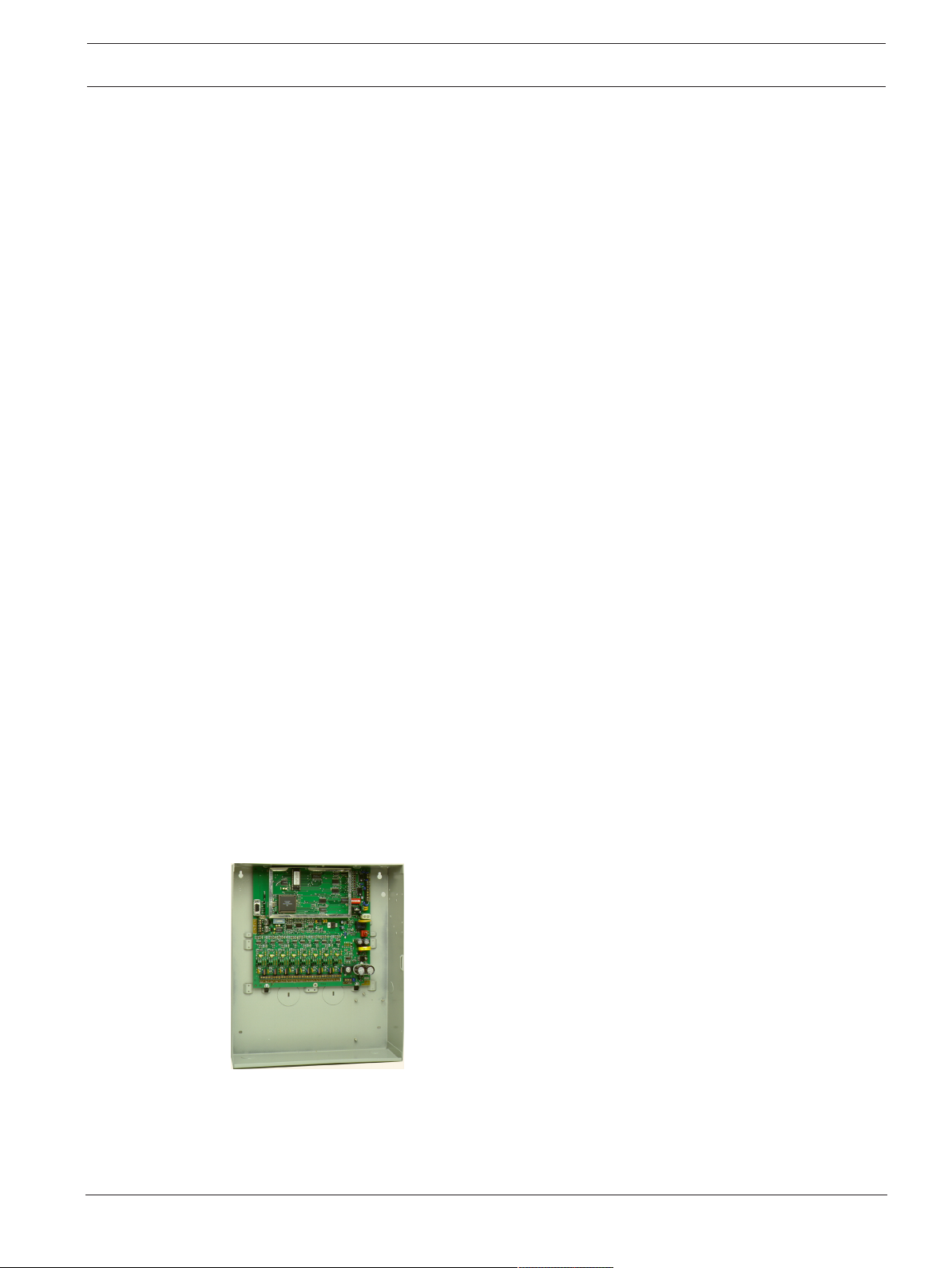
2.9 EA500 transponder
Features
– Relays alarm and test signals from the Receiver to the Central Console.
– Can support a combined total of 64 Receivers and Alert Units.
– AC powered with battery backup for all Receivers.
– Can provide power to SE485 Interface and/or Spread Spectrum Radio.
Robert Bosch (SEA) Pte Ltd Training Manual 2017.08 | V2.18.1.0 | DOC
20 en | System components/specifications Security Escort
– Available in a large or small indoor enclosure.
– Monitors Receivers and Alert Units 10 times per second for alarms, tests, tamper
notification, and power loss.
Description
The Transponder is a device controller for up to 64 devices -- any combination of Receivers
and Alert Units. Its primary function is to monitor the Receivers and Alert Units and report
conditions and events to the Central Console via either wire or ProxLink radios. It also
provides power output to certain devices.
Installation
The Transponder can be mounted in one of two different sized enclosures. It is always
mounted indoors. The devices are connected to the Transponder by means of eight four-wire
Multiplex Busses, two wires for power and two wires for data. Each bus is capable of
supporting up to eight devices. A Security Escort System supports up to 255 Transponders.
Configuration
Each Receiver and Alert Unit is identified to its Transponder by a Multiplex Address which is
set during system installation using a multi-position switch on the Receiver or Alert Unit circuit
board. Transponders communicate on the data bus with individual Multiplex devices by
issuing commands, which contain the Receiver or Alert Unit’s Multiplex Address.
Setup and Testing
Each Transponder and the devices connected to it are set up and can be tested remotely from
the Central Console. Also, each Transponder reports any problems, such as low battery,
immediately upon detecting them.
Function During an Alarm
When a Receiver or Alert Unit detects an alarm, it goes into an “Off Normal” state. To quickly
locate any devices which might be in the “Off Normal” state, the Transponder issues global
commands (which are interpreted simultaneously by all of its devices) approximately 10 times
per second. These global commands are followed by commands to specific devices to
determine the nature of the “Off Normal” condition and, in the case of an alarm (or test), to
obtain the Transmitter Identification Number, Transmitter battery condition, and received
signal strength. This information is then sent to the Central Console, by either wire or through
ProxLink radios, where it is used to graphically display the identity of the subscriber
transmitting the alarm and to determine the subscriber’s location.
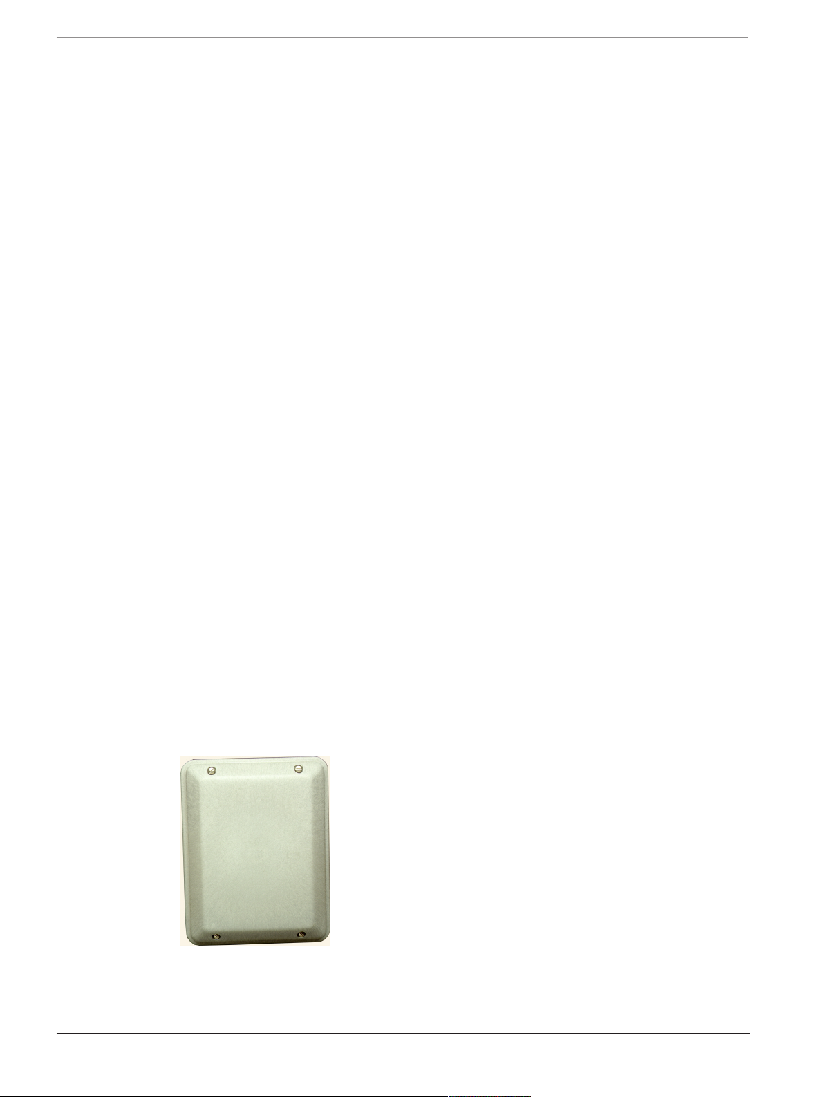
2.10 EA120 alert unit
Features
– Provides output for alarm annunciation through the Siren/Strobe or other third party
switched device.
– Provides output to Siren/Strobe to indicate a successful Transmitter test.
2017.08 | V2.18.1.0 | DOC Training Manual Robert Bosch (SEA) Pte Ltd

Security Escort System components/specifications | en 21
– Indoor and Outdoor enclosures available.
– AC powered with battery backup.
– Activated on command from the Central Station through the Transponder.
– Reports tampering, AC power loss, backup battery power to the Transponder, and output
status.
Description
An Alert Unit is a control module that communicates with the Transponder on the MUX Bus. In
most installations, it is used to activate Siren/Strobe units or other switched devices in the
event of an alarm. The Alert Unit also reports tampering, AC power loss, and backup battery
level to the Transponder.
Installation
The Alert Unit may be housed in either a metal indoor enclosure or an outdoor enclosure
(similar to the Outdoor Receiver enclosure), depending on the application. The Strobe/Siren
units are always mounted in outdoor locations.
Function
The Alert Unit has backup battery power in addition to AC power. The Alert Unit Driver
contains a microprocessor that communicates with the Transponder for Strobe and Siren
commands, status reports, and trouble indications. The troubles monitored are “Tamper”,
“Loss of AC Power”, and “Low Battery”.
Test Acknowledgment
In addition to the function of attracting attention in the event of an emergency, the Strobe unit
is used to acknowledge a successful test of a Transmitter. The Alert Unit can be configured to
cause a Siren to emit a short tone and the strobe to flash for a successful Transmitter test.
Function During an Alarm
In the event of an alarm, the Alert Unit receives a signal from the Transponder and begins
powering the Siren/Strobe (or other switched device). The Siren/Strobe will be active until
the alarm is restored at the Central Console.
Robert Bosch (SEA) Pte Ltd Training Manual 2017.08 | V2.18.1.0 | DOC
22 en | Equipment estimation, location accuracy and receiver location Security Escort
3 Equipment estimation, location accuracy and receiver
location
A Security Escort system installation consists of three major steps:
1. the pre-bid equipment estimation,
2. the pre-construction coverage verification survey, and
3. the post construction setup.
The Security Escort receivers work effectively in a wide variety of installations and can be
placed with confidence provided these installation requirements are met. Therefore, at the
pre-bid stage, it is acceptable to estimate the required equipment. To ensure proper coverage
after proposal acceptance, potential receiver locations can be verified using a standard
receiver in test mode or the portable test receiver before construction begins.
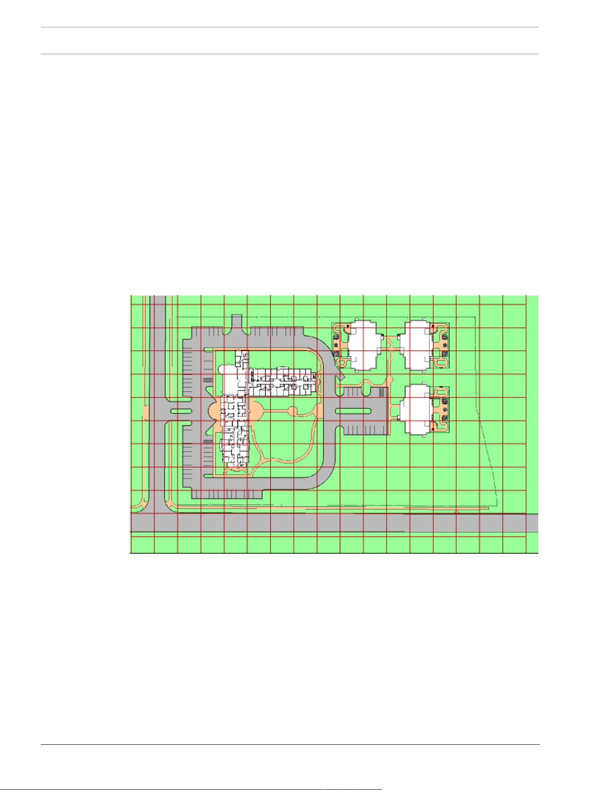
3.1 Location accuracy
The Security Escort system provides quick response to a duress call. Its intent is to dispatch a
responding individual to an area without additional delay to their response to that duress call.
Figure3.1: System Block Diagram
The Security Escort system uses radio frequency (RF) for alarm transmissions. This is
significant because it prevents normal construction from blocking the signal and helps to
eliminate dead spots where the alarm could not be heard. The fact that RF energy passes
through normal construction prevents Security Escort from locating an alarm with 100%
certainty to a specific side of a wall. Alarms originating at or near building walls will typically
be indicated within 7.5 m (25 ft) of the actual location. However, there may be times when the
computed location may appear to be on the other side of the wall.
The Security Escort system was designed to provide a computed alarm location typically
within 7.5 m (25 ft) of the actual location when indoors, and a computed alarm location
typically within 15 m (50 ft) of the actual location outdoors. Any deviation from the following
installation guidelines will degrade the computed location accuracy. Therefore, to achieve
accuracy, the following installation guidelines must be adhered to.
2017.08 | V2.18.1.0 | DOC Training Manual Robert Bosch (SEA) Pte Ltd
Security Escort Equipment estimation, location accuracy and receiver location | en 23
3.2 Pre-bid equipment estimation
The pre-bid equipment estimation is performed prior to bidding the installation. At this point,
it must be determined what type of coverage is desired, and where the coverage will be
required. For example, the amount of equipment required for a full-coverage (indoor and
outdoor) system in a multi-building application is greater than an installation that requires
outdoor only coverage. The customer should be consulted, and the areas of most concern
should be given special consideration.
3.2.1 Initial equipment estimate
Number of indoor receivers
To estimate the number of indoor receivers, first read Indoor receiver installation. Assume the
receivers are placed on a grid with a maximum spacing of 25 m (80 ft) between receivers for
standard construction. In multi-floor applications the receivers on each floor must be placed
directly above the receivers on the floor below (this is required for proper floor-to-floor
location).
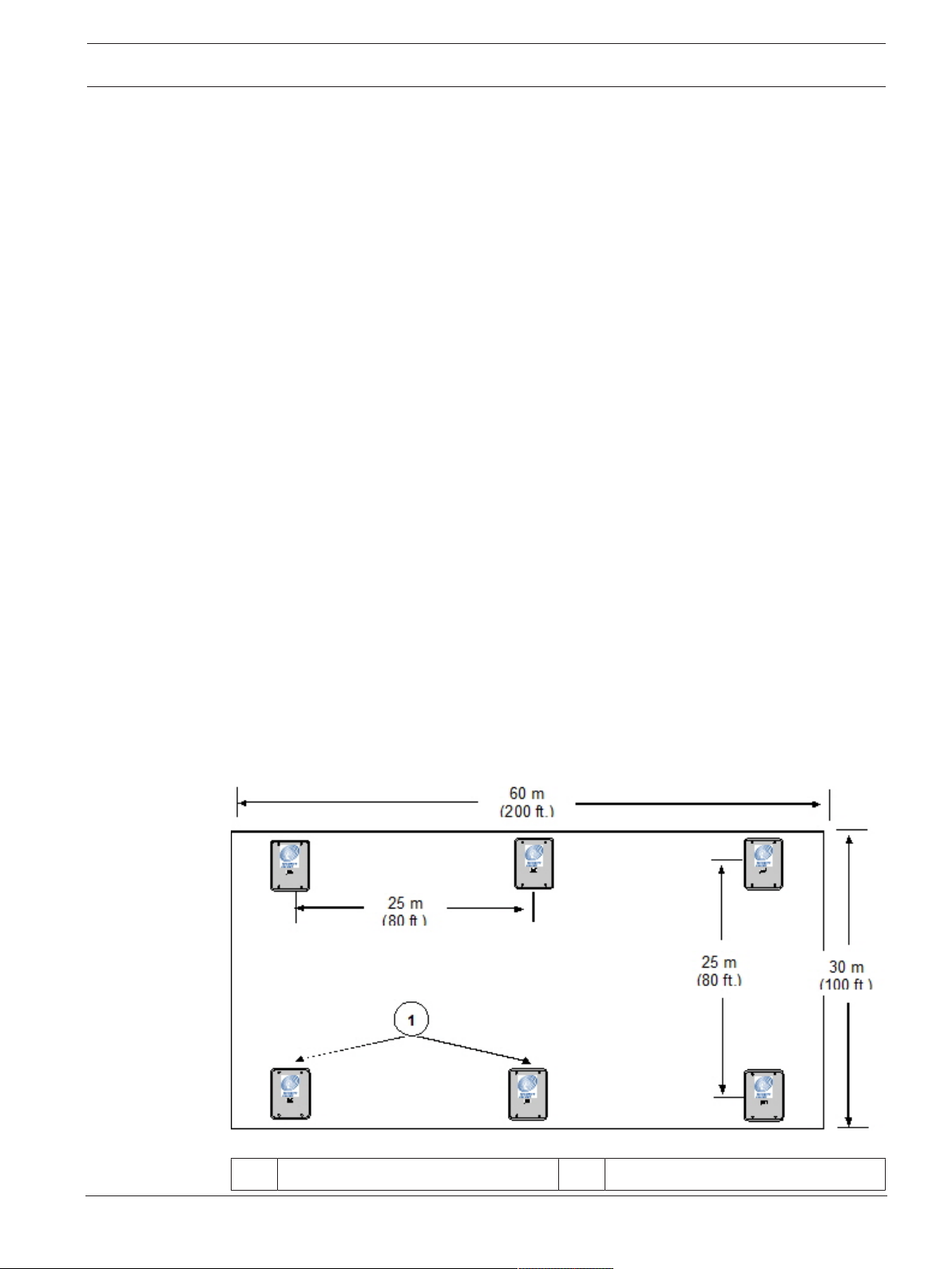
For example, to determine the number of receivers required to protect a building of standard
construction of 60 m x 30 m (200 ft x 100 ft) and four floors:
1. To determine the number of receivers in each direction, divide each dimension of the
building by 25 m (80 ft), drop the remainder, and add 1. For example:
– 60 m/25 m = 2.4, becomes 2, add 1 = 3
(200 ft/80 ft = 2.5, becomes 2, add 1 = 3)
– 30 m/25 m =1.2, becomes 1, add 1 = 2
(100 ft/80 ft =1.25, becomes 1, add 1 = 2)
2. To determine the number of receivers required per floor, multiply the number of receivers
in one direction by the number of receivers in the other direction.
(3 x 2 = 6) 6 receivers per floor.
3. To determine the total number of receivers, multiply the number of receivers per floor by
the number of floors.
(6 x 4 = 24) 24 receivers for the building.
Figure3.2: Determining the Number of Indoor Receivers Required
1 Receivers (6)
Robert Bosch (SEA) Pte Ltd Training Manual 2017.08 | V2.18.1.0 | DOC
24 en | Equipment estimation, location accuracy and receiver location Security Escort
Each floor would require 6 receivers, resulting in a total of 24 receivers to protect this
building.
For the best location accuracy, consistent receiver spacing is important. Do not place
receivers significantly closer in one section of a building than another section.
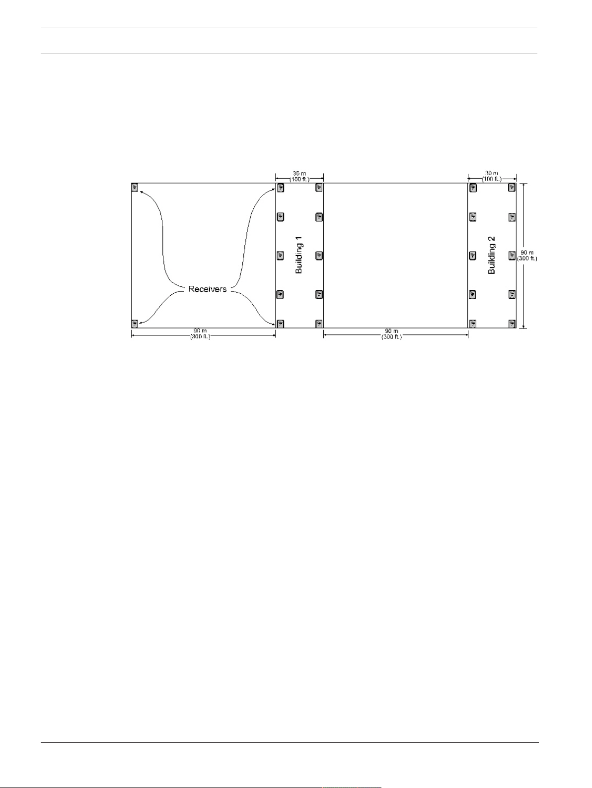
Number of outdoor receivers
To estimate the number of receivers, first read Outdoor receiver installation. Assume a
maximum receiver spacing of 90 m (300 ft) between receivers, in both directions, for receivers
that are not within 30 m (100 ft) of a building with inside coverage. Receivers within 30 m
(100 ft) of a building should be spaced the same as receivers in the building (spacing the
outside receivers at a somewhat larger spacing is acceptable in most cases).
An outside area directly between two buildings with inside protection will need no additional
receivers if the buildings are 90 m (300 ft) or less apart. If the buildings are more than 90 m
(300 ft) apart the outside receivers should be evenly spaced between the buildings. Make sure
the standard 90 m (300 ft) spacing is not exceeded. For spacing outside adjacent to a covered
building, start the 90 m (300 ft) spacing at the building wall.
Allowance for special coverage requirements
For purposes of the bid, the number of receivers estimated above should be raised by 5% to
allow for special coverage considerations and RF problem areas.
Number of transponders
Assume one transponder per building for indoor installations. If wiring can be run from other
buildings or from outdoor receivers, they may be connected to one transponder. Never exceed
the total number of 64 devices (receivers and alert units) per transponder. All outside wiring
must be under ground, or in metal conduit.
Number of receivers and alert units per bus
For transponders, each bus can handle 8 receivers and alert units. However, it is a good idea
to leave some addresses available on each bus to allow for future expansion. For systems with
a high number of supervised transmitters, see Transponder wiring notes.
2017.08 | V2.18.1.0 | DOC Training Manual Robert Bosch (SEA) Pte Ltd

Security Escort Equipment estimation, location accuracy and receiver location | en 25
Bus wire
The multiplex bus for transponder should be wired with 4 conductor 18 gauge (1.2 mm) wire.
The wire should not be paired or shielded. In the United States this is the same as fire system
wire, except it should not be red.
Number of alert units
The number of alert units will be determined by each system’s requirements. In general,
enough alert units should be installed to be heard and seen from all outdoor locations of
protection. Remember that even in a silent system, alert units can be used outside to provide
test feedback. Horn/strobe units should be mounted in predictable locations to make them
easy to identify by subscribers. Alert units are not required indoors because the indoor
receiver provides alarm and test feedback. Each transponder will drive one siren and one
strobe if they are less than 15 m (50 ft) from the transponder.
It is a good idea for each protected parking lot to have a siren/strobe near it.
3.3 Pre-construction coverage verification survey
The pre-construction coverage verification survey is performed after the bid is accepted and
before construction begins. It is done to determine the location of each receiver. Each receiver
location should be checked using a standard receiver in the test mode.
3.3.1 Verify each potential receiver location
Using a receiver in “receiver spacing” mode
”Receiver spacing” mode is enabled with jumper P5 in place (jumper P4 removed) on a
receiver (see the EA102 Receiver Installation Instructions).
This mode is exactly the same as the “test” mode, except that only transmissions with an
adequate receive margin are sounded. This indicates the maximum acceptable spacing of
receivers. Use the following procedure to test the spacing of receivers:
1. Mount the first receiver.
2. Put jumpers P1, P2, P3, and P5 in place, and remove all other jumpers. Power the
receiver from a or 12 VDC source.
3. Take the second receiver and a transmitter a distance away from the first receiver.
4. Activate the transmitter.
5. If receiver 1 sounds the test beep, receiver 2 is within range. Repeat this test until
receiver 1 no longer sounds the test beeps. Move back to the last location where receiver
1 received the test beeps. This location marks the maximum spacing between receivers.
The distance between receivers should not exceed 25 m (80 ft) indoors and 90 m (300 ft)
outdoors. Mount receiver 2 at this location or closer to receiver 1.
Notice!
Do not use the “test” mode (jumper P4) to determine receiver spacing.
Robert Bosch (SEA) Pte Ltd Training Manual 2017.08 | V2.18.1.0 | DOC

26 en | Equipment estimation, location accuracy and receiver location Security Escort
Figure3.3: Receiver Spacing
1 Receiver 1 stops sounding the test
3 Receiver 2 at maximum range
beeps when receiver 2 is moved past
this point
2 Receiver 1 4 Receiver 2 beyond maximum range
Using a transponder, receivers, and laptop computer to determine receiver location
Notice!
System software and an area map must be installed on a laptop computer to use this method.
A transponder with long multiplex wires connected to receivers can be used to see actual
alarm location before the receivers are placed. Place the receivers in the proposed locations
wired back to the transponder. Program the receivers with their locations in the Transponder
Database. Using the maintenance transmitter and the maintenance alarm database, activate
alarm transmissions within the area surrounded by the temporarily placed receivers. Verify
that the location accuracy is acceptable at all points of concern. If not acceptable move the
receivers, update the receiver location in the Transponder Database, and retest. Do not test
outside of the last receiver in any direction, as this gives incorrect locations. Repeat this test
in all areas of different construction and concern at the site.
3.3.2 Indoor receiver installation
– Indoor receivers must be mounted in a evenly spaced grid no more than 25 m (80 ft)
apart.
– Indoor receivers must be mounted 1.5 to 1.8 m (5 ft to 6 ft) above the floor. This is true
even if this is a single story building. Do not mount receivers above the ceiling or in roof
rafters.
– In multistory buildings, the receivers must be mounted directly above the receivers on the
floor below. The same number of receivers must be used on each floor level. If you meet
all of the indoor installation guidelines, you can expect the computed location to indicate
the correct floor about 95% of the time.
– Receivers must not be mounted within 30 cm (1 ft) of any metal object, including wire
mesh, metal foil, metal pipe and HVAC ducting in walls.
2017.08 | V2.18.1.0 | DOC Training Manual Robert Bosch (SEA) Pte Ltd

Security Escort Equipment estimation, location accuracy and receiver location | en 27
– Take care that large metal objects do not shield a receiver from a protected area. For
example metal staircases, metal food serving lines, metal walls, lead lined walls, metal
roofs, wire mesh in walls, walk-in freezers and refrigerators.
For the best indoor and outdoor location or an indoor only system
– Mount the indoor receivers on the recommended 25 m (80 ft) grid, with the last row of
indoor receivers on the outside wall of the building. Do this even if the building is less
than 25 m (80 ft) wide or long.
– There should be a receiver at each outside corner of a building.
Handling two protected buildings sharing a common wall with floor levels that do not match
– Ask the customer which building has areas of greater concern and favor the
recommended mounting heights in that building.
– The recommended 25 m (80 ft) maximum indoor spacing grid should be maintained
throughout both buildings as if the wall in question was not there. Mounting heights only
for those receivers at or near (within 6 m [20 ft]) the wall in question should be affected.
Mounting heights for all other receivers in the buildings must follow the indoor
recommendation. Mark the recommended mounting height for receivers on the higher
floor level and also mark the recommended mounting height for receivers on the lower
floor level. Mount the receiver at its normal grid location midway between these two
heights, but not above the ceiling level of the lower floor.
3.3.3 Outdoor receiver installation
– Outdoor receivers must be mounted in a evenly spaced grid no more than 90 m (300 ft)
apart.
– Outdoor receivers must be mounted 3 m (10 ft) above the ground.
– Receivers must not be mounted within 30 cm (1 ft) of any metal object, including fences,
metal walls and walls with wire mesh. If a receiver is mounted on a metal fence, that
fence should be grounded (not floating or insulated from ground) and the receiver should
be spaced 30 cm (1 ft) from the fence and 3 m (10 ft) above the ground.
– Take care that large metal objects do not shield a receiver from a protected area. For
example; metal fences, metal staircases, metal buildings, power transformers and metal
roofs.
– Receiver locations should be below building overhangs and eaves as these can shield the
areas below them.
– Receivers should have a clear line of sight of the protected area. Therefore, take care
where the ground is hilly or uneven, that there are no areas and low spots where several
receivers can’t hear the signal.
Transition areas between indoor and outdoor areas
– An outside area directly between two buildings with complete indoor protection will need
no additional receivers between the buildings, if they are 90 m (300 ft) or less apart.
– When protecting an outside area directly between two buildings with complete indoor
protection, and they are more than 90 m (300 ft) apart, place a row of outside receivers
evenly spaced between the buildings. Make sure the receiver row does not exceed the
standard 90 m (300 ft) spacing from the buildings. The spacing between receivers in that
row should be about the same as the spacing for the receivers in the buildings.
Robert Bosch (SEA) Pte Ltd Training Manual 2017.08 | V2.18.1.0 | DOC

28 en | Equipment estimation, location accuracy and receiver location Security Escort
– Indoor receivers should be no more than 25 m (80 ft) apart and outdoor receivers should
be no more that 90 m (300 ft) apart. Both of these recommendations work well in their
respective areas. However, if a building is adjacent to an outdoor area, that building will
have a greater density of receivers and, therefore, has a tendency to pull the computed
location towards it. To counteract the building tendency to pull the location, consider the
following special cases:
– If the outdoor area adjacent to the building is wide open and the customer is not
concerned about reduced location accuracy in this area, then nothing special needs
to be done. Follow the normal indoor and outdoor recommendations.
– The building is near the boundary of the protected area, with or without a fence at
the boundary. The receivers in the building should be placed at the recommended 25
m (80 ft) spacing. The receivers at the boundary of the protected area near the
building should be spaced about the same as those in the building, approximating
the same grid as used in the building.
– The building is adjacent to a large protected outdoor area that extends for more than
90 m (300 ft) from the building. The receivers in the building should be placed at the
recommended 25 m (80 ft) spacing. The receivers in the large protected outdoor
area should be placed on the normal 90 m (300 ft) grid except for the first row of
receivers adjacent to the building. This first row of outdoor receivers in the transition
area should “split the difference” between the indoor and outdoor spacing at about
60 m (200 ft).
Boundary areas at the outer edge of the protected area
The system cannot locate an alarm past the last receiver at the boundary of the protected
area. Therefore, the last row of receivers must be at or past the end of the protected area.
2017.08 | V2.18.1.0 | DOC Training Manual Robert Bosch (SEA) Pte Ltd

Security Escort System wiring | en 29
4 System wiring
4.1 General guidelines
After the site survey (and special pre-construction verifications) has been completed, the
wiring can be run between the proposed locations of the system components and the Central
Console. See specific installation instructions accompanying each component for wiring
details.
The following table indicates the specifications for the wiring:
Application Diagram
From To
Transponder Transformer 1 1.5 mm
Alert Unit 2 1.2 mm
Receiver 2 1.2 mm
SE485 3 0.5 mm
Siren/Strobe 4 1.2 mm
Ref
Gauge Conductors Maximum
(16
AWG)
(18
AWG)
(18
AWG)
(24
AWG)
(18
AWG)
Distance
2 15 m (50 ft) Standard
4 900 m (3000
ft) per bus
4 900 m (3000
ft) per bus
4 wire, 2
twisted pair
4 15 m (50 ft) Solid, not
See
Transponder
– SE485
Wiring table.
Notes
lamp cord
Solid, not
twisted, not
shielded
Solid, not
twisted, not
shielded
IMPORTANT!
Must be
twisted pair,
not shielded.
CAT5 cable
preferred.
twisted, not
shielded
Alert Unit Transformer 5 1.5 mm
(16
AWG)
Siren/Strobe 6 1.5 mm
(18
AWG)
Tab.4.1: Wiring Guidelines
2 15 m (50 ft) Standard
lamp cord
4 15 m (50 ft) Solid, not
twisted, not
shielded
4.1.1 Transponder - SE485 wiring table
Number of
Transponders
1 to 4 6100 m (20000 ft)
8 3050 m (10000 ft)
12 1525 m (5000 ft)
Robert Bosch (SEA) Pte Ltd Training Manual 2017.08 | V2.18.1.0 | DOC
Maximum Wire
Length
30 en | System wiring Security Escort
Number of
Transponders
16 900 m (3000 ft)
Tab.4.2: Transponder – SE485 Wiring Table
Maximum Wire
Length
4.1.2 Observe established standards
Install cable according to local code requirements. In the USA, refer to the National Electrical
Code Standards, located in Chapter 8 Article 800 of the National Electrical Code, and applicable
local and regional codes.
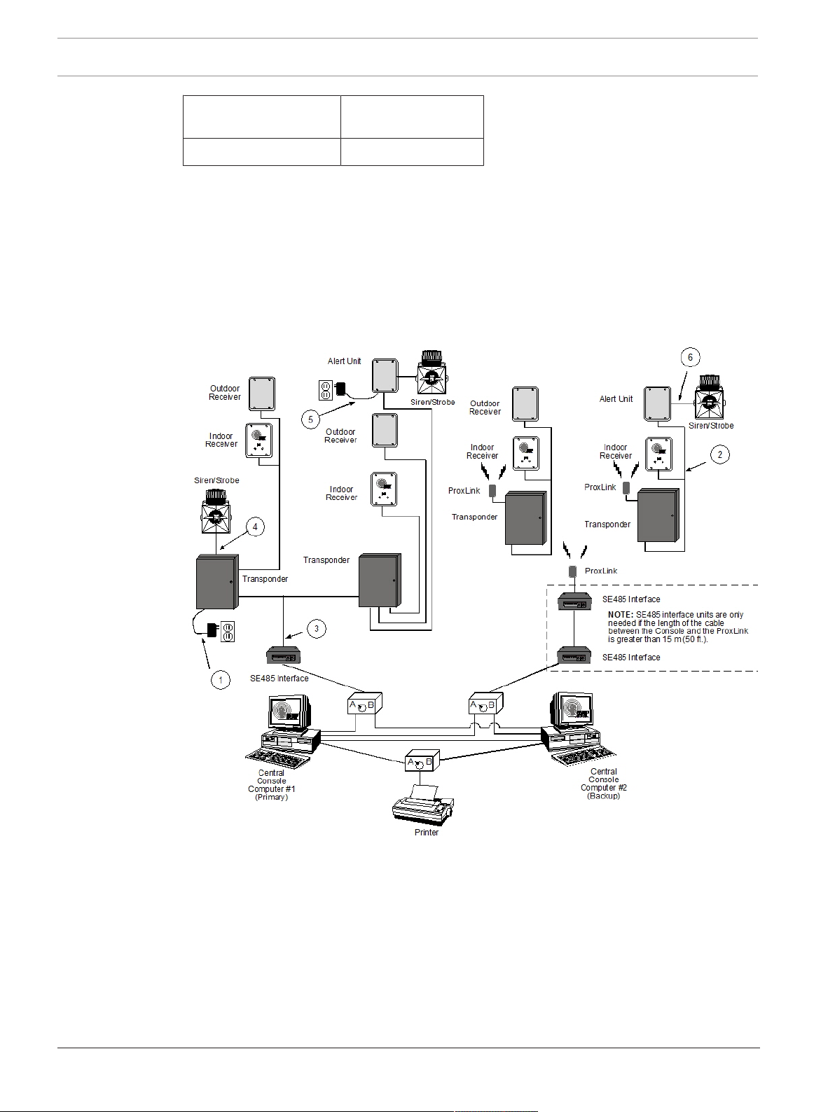
4.2 Component wiring guidelines
4.2.1 General wiring diagram
Figure4.1: General Wiring Diagram
2017.08 | V2.18.1.0 | DOC Training Manual Robert Bosch (SEA) Pte Ltd
Loading...