


IPH8010
Table of contents
 Loading...
AT&T U-verse
Pace
IPTV Receivers
Product Manual
Supports Models IPH8005, IPH8010, and IPH8110
For use with your AT&T U-verse
®
TV service


3
Contents
Introduction . . . . . . . . . . . . . . . . . . . . . . . . . . . . . . . . . . . . 5
Package contents. . . . . . . . . . . . . . . . . . . . . . . . . . . . . . . . . . . . . . . . . . . . . . . . . . . 6
Serial number . . . . . . . . . . . . . . . . . . . . . . . . . . . . . . . . . . . . . . . . . . . . . . . . . . . . . . 6
Front panel . . . . . . . . . . . . . . . . . . . . . . . . . . . . . . . . . . . . . . . . . . . . . . . . . . . . . . . . 7
Back panel . . . . . . . . . . . . . . . . . . . . . . . . . . . . . . . . . . . . . . . . . . . . . . . . . . . . . . . . 8
Connecting the Receiver . . . . . . . . . . . . . . . . . . . . . . . . . . 9
Connect the receiver to the home network. . . . . . . . . . . . . . . . . . . . . . . . . . . . . . . 10
Connect the receiver to the TV. . . . . . . . . . . . . . . . . . . . . . . . . . . . . . . . . . . . . . . . 11
Determining the type of connection to use. . . . . . . . . . . . . . . . . . . . . . . . . . . . . 11
Using an HDMI connection . . . . . . . . . . . . . . . . . . . . . . . . . . . . . . . . . . . . . . . . 13
Using a DVI connection with digital audio . . . . . . . . . . . . . . . . . . . . . . . . . . . . . 14
Using a DVI connection with analog audio . . . . . . . . . . . . . . . . . . . . . . . . . . . . 15
Using a component video connection with digital audio . . . . . . . . . . . . . . . . . . 16
Using a component video connection with analog audio . . . . . . . . . . . . . . . . . . 17
Using a composite video connection . . . . . . . . . . . . . . . . . . . . . . . . . . . . . . . . . 18
Using an RF coaxial connection . . . . . . . . . . . . . . . . . . . . . . . . . . . . . . . . . . . . 19
Connecting the receiver to a home theater system . . . . . . . . . . . . . . . . . . . . . . 20
Plug in the receiver. . . . . . . . . . . . . . . . . . . . . . . . . . . . . . . . . . . . . . . . . . . . . . . . . 21
Troubleshooting and Support. . . . . . . . . . . . . . . . . . . . . . 22
Troubleshooting . . . . . . . . . . . . . . . . . . . . . . . . . . . . . . . . . . . . . . . . . . . . . . . . . . . 22
Frequently asked questions . . . . . . . . . . . . . . . . . . . . . . . . . . . . . . . . . . . . . . . . . . 24
Picture formats . . . . . . . . . . . . . . . . . . . . . . . . . . . . . . . . . . . . . . . . . . . . . . . . . . . . 25
Safety Information . . . . . . . . . . . . . . . . . . . . . . . . . . . . . . 26
Warnings . . . . . . . . . . . . . . . . . . . . . . . . . . . . . . . . . . . . . . . . . . . . . . . . . . . . . . . . 26
Other warnings . . . . . . . . . . . . . . . . . . . . . . . . . . . . . . . . . . . . . . . . . . . . . . . . . . . . 26
Important safety instructions . . . . . . . . . . . . . . . . . . . . . . . . . . . . . . . . . . . . . . . . . 27
Safety aspects of connections . . . . . . . . . . . . . . . . . . . . . . . . . . . . . . . . . . . . . . . . 29
Note to the installer . . . . . . . . . . . . . . . . . . . . . . . . . . . . . . . . . . . . . . . . . . . . . . . . 30
Compliance Information . . . . . . . . . . . . . . . . . . . . . . . . . . 31
Regulatory information . . . . . . . . . . . . . . . . . . . . . . . . . . . . . . . . . . . . . . . . . . . . . . 31
Declaration of Conformity . . . . . . . . . . . . . . . . . . . . . . . . . . . . . . . . . . . . . . . . . 31
Trademarks and licenses . . . . . . . . . . . . . . . . . . . . . . . . . . . . . . . . . . . . . . . . . . . . 33
Open source licenses . . . . . . . . . . . . . . . . . . . . . . . . . . . . . . . . . . . . . . . . . . . . 33

4
5
Introduction
Welcome to AT&T’s U-verse video service. The IPH8005, IPH8010, and IPH8110
U-verse receivers bring a new set of interactive services directly to you through your
TV and your in-home IP network. The receiver uses your existing in-home coaxial
cable for HPNA connections or Ethernet home network wiring and connects to most
entertainment devices.
The following IPTV services may be available through this receiver:
• Digital Video Recorder (DVR). Allows you to record your favorite programs to an
internal hard disk and watch them at your convenience.
• Pause Live TV. Allows you to pause the live TV and resume watching your
programming from where you left it.
• High-Definition (HD). Provides high-resolution video and Dolby Digital audio.
• Video-On-Demand (VOD). Gives you access to a library of movies and programs
that you can watch, when you want to watch them.
With your receiver’s DVR functionality, you can do the following:
• Pause live TV.
• Instantly replay live TV.
• Fast-forward up to the point of live TV.
• Rewind through a program that you are currently watching.
• Record high-definition content (as well as standard definition).
• Watch your recorded programs on other receivers in the household with AT&T’s
Total Home DVR feature.
• Record up to four programs while watching previously recorded programs.
• Schedule your receiver to record a program or a whole series.
• Manage your stored recordings.
• Retain full control over any parental viewing restrictions you have set up.
POWER
IPH8XXX
LINK
RECORDHD
MENU
OK
6
You control your receiver’s DVR functions and other U-verse features using your
remote control. Consult the information provided by AT&T U-verse for more details or
visit the online feature guide at www.att.com/userguides.
Package contents
The receiver carton contains the following items:
• IPH8005, IPH8010, or IPH8110 receiver. A TV receiver that supports high-definition
(HD) and standard-definition (SD) video decoding.
• Power cord and adapter. A 12 volt power supply unit that provides power from an
AC wall outlet to the receiver.
• Product Manual. A product manual that provides connection information for the
IPH8005, IPH8010, and IPH8110 receivers.
Before using the receiver, read the “Important safety instructions” on page 27 of this
manual. This manual describes how to connect your receiver to both your in-home IP
network and your entertainment system. The manual also outlines safeguards and
installation information. The safety information contained in this manual was
developed and provided solely by the receiver manufacturer, Pace Americas.
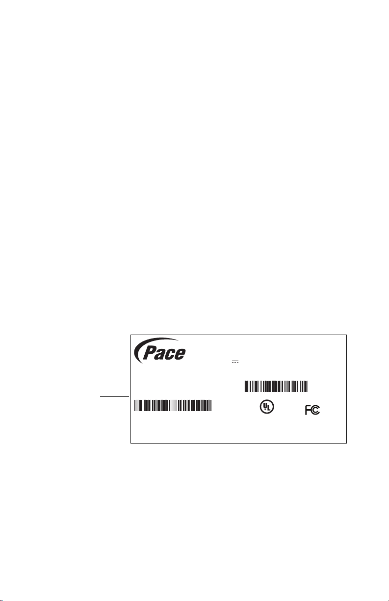
Serial number
At times AT&T may ask for your serial number. To find the serial number, look on the
bottom of the receiver for the label. The serial number is the numeric code to the right
of the letters “S/N” on the label, as shown on the following sample label.
Use the space below to record the serial number for your receiver:
_________________________________
GUID: c440f5e7-2b49-41f5-8b07-b9f478946384
Model: IPH8XXX
AT&T U-verse DVR
Basic SD/HD
Rating: 12V 1.5A
HW: AK
SW: IPTVL- 1015
Factory ID: CCT
Made in Thailand
Manufactured under license from Dolby
Laboratories. Dolby and the double-D symbol
are trademarks of Dolby Laboratories.
HPNA MAC: 48:44:48:de:ac:8b
Pace
IPH8010
LISTEDLISTED
I.T.E.
E205389
USUSCC
Date of Mfg: 12/2013
S/N: 1234567890123
ICES/NMB-003 B
P/N: 296-0411700
Serial number
location
7
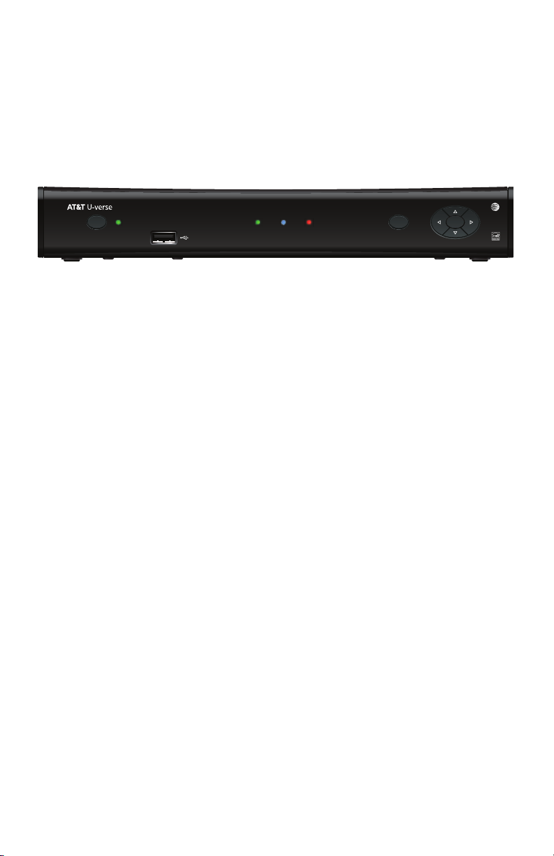
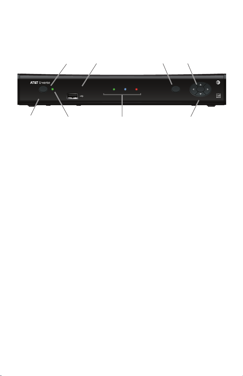
Front panel
The following illustration shows the buttons, lights, and connectors on the front of the
receiver.
Power button
Turns the set-top box on or off.
Power light
Lights green when the set-top box is powered on. Blinks when receiving input from the
remote control or when the front-panel buttons are pressed.
Model number
Identifies the model number of the receiver.
USB port
Reserved for future use.
Link light
Lights green when the box has a good connection to the AT&T network.
HD light
Lights blue to indicate the receiver is configured to display high-definition programming
when available.
Record light
Lights red when the DVR is recording content.
Menu button
Launches the on-screen menu.
Navigation buttons
Navigates to on-screen menu options.
OK button
Confirms the on-screen menu choice.
POWER
IPH8XXX
LINK
RECORDHD
MENU
OK
Power button Menu button
Navigation buttons
USB port
Model number
Status lights
OK button
Power light
8
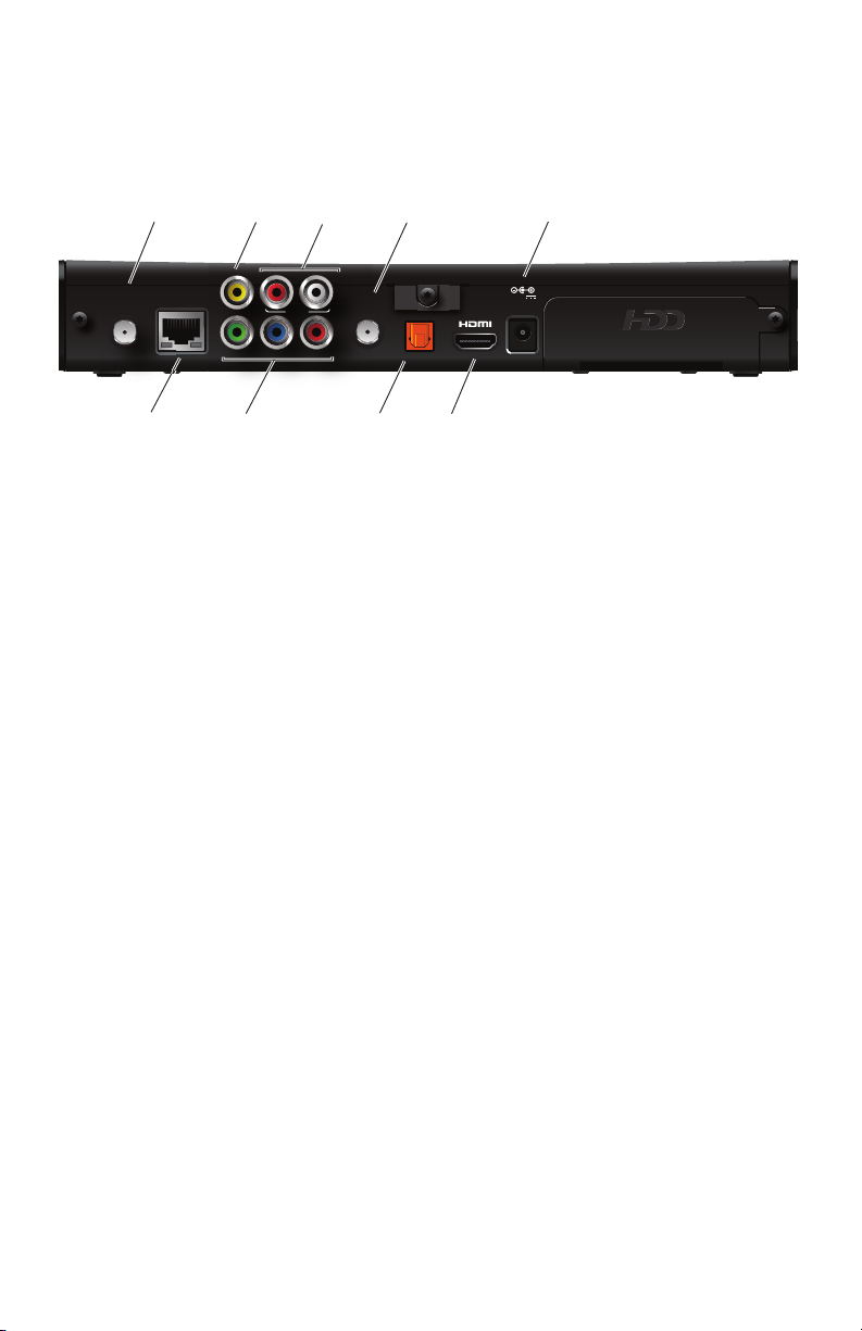
Back panel
The following illustration shows the ports and connectors on the back of the receiver.
TO WALL (VIDEO IN)
Connects the HPNAv3 in-home network over coaxial cable, if applicable.
NETWORK
Connects the Ethernet network cable, if applicable.
Y Pb Pr
Connects the receiver to a high-definition TV or home theater receiver using a
component video connection.
VIDEO OUT
Connects the receiver to a standard-definition TV using a composite video connection.
AUDIO
Connects the receiver to a TV or home theater receiver using an analog audio
connection.
TO TV
Connects the set-top box to the RF/Antenna connector on your TV or VCR (optional).
OPTICAL
Connects the receiver to a TV or home theater receiver using a digital audio
connection.
HDMI
Connects the receiver to a high-definition TV or home theater receiver using an HDMI
connection.
POWER
Connects the power adapter to the receiver. The LED lights green when the receiver is
receiving power from the wall outlet.
TO WALL
(VIDEO IN)
AUDIO
YPbPr
VIDEO OUT
R
L
NETWORK
TO TV
OPTICAL
POWER
+12V
1.5A MAX.
Coaxial
input
Component
video
output
Analog
audio
output
HDMI
output
Network
port
Composite
video
output
Power
Digital audio
output
(optical)
RF
output

9
Connecting the Receiver
To view programs broadcast in high definition, your receiver must be connected to a
suitable high-definition TV or computer monitor. Your receiver is also compatible with
standard-definition TVs.
Your receiver should have been connected to your TV by your installer. However, if you
need to disconnect and re-connect your equipment, please read the information in this
chapter carefully before you re-connect the receiver to your TV.
Before you begin:
• Do not connect your receiver (or any other equipment such as a TV or DVD player)
to the AC power supply until you have properly connected all the other cables.
• Disconnect your receiver from the AC power supply before you disconnect any
other equipment from its rear panel.
• To disconnect power from your receiver, always detach the power supply unit from
the wall electrical outlet (rather than removing the cord from your receiver). You
should install your receiver near a wall electrical outlet that is easily accessible.
• The TO WALL (VIDEO IN) connector is designed for connection to an HPNAv3 in-
home network over coaxial cable. You must not connect any other equipment to this
input.
• Any cable connected to the OPTICAL connector must be a fiber optic TOSLINK
connector, not a regular audio cable.
• If you are in any doubt about the power supply cord, its plug or its connection,
consult a qualified electrician.
• Use the TV remote to set the input to match the connector selected on the back of
the TV.
10
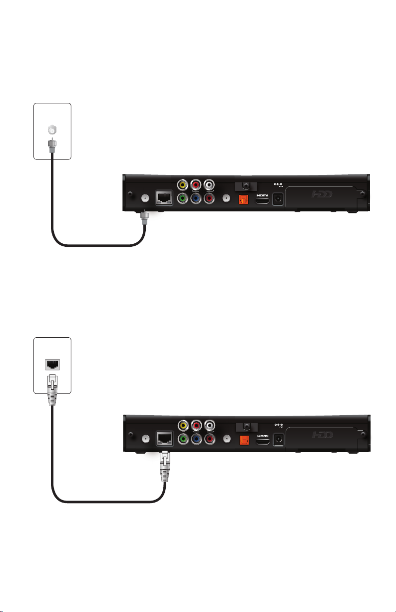
Connect the receiver to the home network
If you connect to your IPTV signal from your HPNAv3 in-home network over coaxial
cable, use the TO WALL (VIDEO IN) connector on the back panel of the receiver to
connect to the HPNAv3 in-home network through a coaxial cable.
If you connect to your home network with an Ethernet (Cat-5) cable, use the
NETWORK connector on the back panel of the receiver to connect to the home
network Ethernet port.
Note: Use only one of these connections to access your home network.
TO WALL
(VIDEO IN)
AUDIO
YPbPr
VIDEO OUT
R
L
NETWORK
TO TV
OPTICAL
POWER
+12V
1.5A MAX.
Wall outlet
Coaxial cable
Receiver
TO WALL
(VIDEO IN)
AUDIO
YPbPr
VIDEO OUT
R
L
NETWORK
TO TV
OPTICAL
POWER
+12V
1.5A MAX.
Wall outlet
Ethernet cable
Receiver
11
Connect the receiver to the TV
The connections for an HD or SD TV are different, and before you begin, you must
determine if your TV is HD or SD. Your TV must receive HD signals for you to enjoy the
benefits of HDTV. Refer to the manual that came with your TV for more information.
Determining the type of connection to use
The connection type you use is determined by the type of connections on your TV or
home theater receiver. The following tables list the connectors that can be used for
high-definition TVs and standard-definition TVs, respectively.
Connections for HDTV
To use the receiver with high-definition TVs, you need to use one of the following
connections to view HD content. For more information about making HDTV
connections, check the owner’s manual for your TV and the appropriate connection
diagrams in this manual.
Note: The labeling on your HDTV may vary slightly from the illustrations shown in the
table.
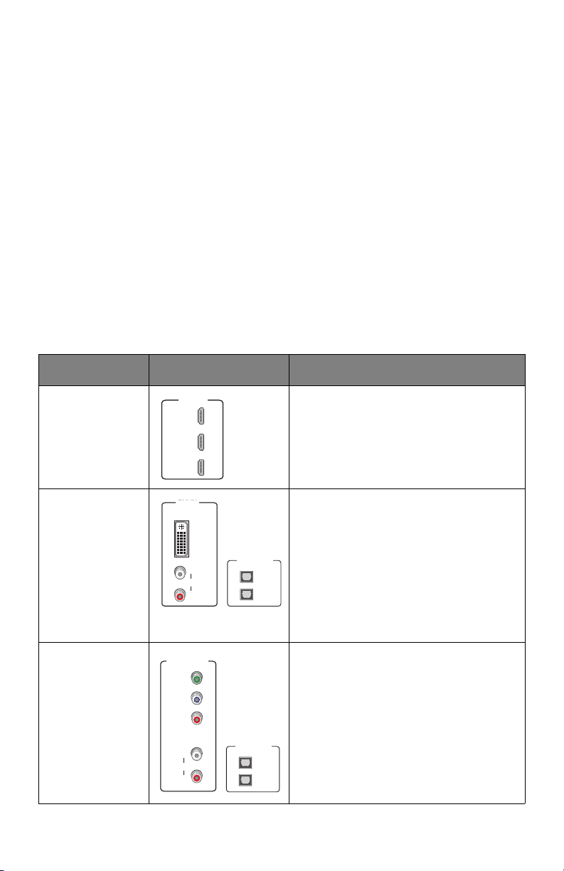
Name Connector Description
HDMI Provides the HD connection using an
HDMI input on the TV. The HDMI-to-HDMI
connection transmits both HD video and
digital audio. For connection information
using HDMI, see “Using an HDMI
connection” on page 13.
DVI Provides the HD connection using a DVI
input on the TV. The HDMI-to-DVI
connection transmits HD video only. For
digital audio, use a TOSLINK fiber optic
cable to connect to the digital audio
connector on the TV. For standard audio,
use the Audio L/R RCA connectors. For
connection information using DVI, see
“Using a DVI connection with digital audio”
on page 14.
Component video Provides the HD connection using the
component video input on the TV. For
digital audio, use a TOSLINK fiber optic
cable to connect to the digital audio
connector on the TV. For standard audio,
use the Audio L/R RCA connectors. For
connection information using component
video, see “Using a component video
connection with digital audio” on page 16.
HDMI IN
1
2
3
HDMI IN
1
2
3
DVI IN
L
R
AUDIO
L
R
AUDIO
DVI IN
OPTICAL IN
1
2
Y
P
B
P
R
COMPONENT
VIDEO IN
L
R
AUDIO
Y
P
B
P
R
L
R
AUDIO
COMPONENT
VIDEO IN
OPTICAL IN
1
2
Loading...