


M4N98TD EVO
Motherboard

E5365
First Edition (V1)
February 2010
Copyright © 2010 ASUSTeK COMPUTER INC. All Rights Reserved.
No part of this manual, including the products and software described in it, may be reproduced, transmitted, transcribed, stored in a retrieval system, or translated into any language in any form or by any means, except documentation kept by the purchaser for backup purposes, without the express written permission of ASUSTeK COMPUTER INC. (“ASUS”).
Product warranty or service will not be extended if: (1) the product is repaired, modified or altered, unless such repair, modification of alteration is authorized in writing byASUS; or (2) the serial number of the product is defaced or missing.
ASUS PROVIDES THIS MANUAL “AS IS” WITHOUT WARRANTY OF ANY KIND, EITHER EXPRESS OR IMPLIED, INCLUDING BUT NOT LIMITED TO THE IMPLIED WARRANTIES OR CONDITIONS OF MERCHANTABILITY OR FITNESS FOR A PARTICULAR PURPOSE. IN NO EVENT SHALL ASUS, ITS DIRECTORS, OFFICERS, EMPLOYEES OR AGENTS BE LIABLE FOR ANY INDIRECT, SPECIAL, INCIDENTAL, OR CONSEQUENTIAL DAMAGES (INCLUDING DAMAGES FOR LOSS OF PROFITS, LOSS OF BUSINESS, LOSS OF USE OR DATA, INTERRUPTION OF BUSINESS AND THE LIKE), EVEN IF ASUS HAS BEEN ADVISED OF THE POSSIBILITY OF SUCH DAMAGES ARISING FROM ANY DEFECT OR ERROR IN THIS MANUAL OR PRODUCT.
SPECIFICATIONS AND INFORMATION CONTAINED IN THIS MANUAL ARE FURNISHED FOR INFORMATIONAL USE ONLY, AND ARE SUBJECT TO CHANGE AT ANY TIME WITHOUT NOTICE, AND SHOULD NOT BE CONSTRUED AS A COMMITMENT BY ASUS. ASUS ASSUMES NO RESPONSIBILITY OR LIABILITY FOR ANY ERRORS OR INACCURACIES THAT MAY APPEAR IN THIS MANUAL, INCLUDING THE PRODUCTS AND SOFTWARE DESCRIBED IN IT.
Products and corporate names appearing in this manual may or may not be registered trademarks or copyrights of their respective companies, and are used only for identification or explanation and to the owners’ benefit, without intent to infringe.
Offer to Provide Source Code of Certain Software
This product may contain copyrighted software that is licensed under the General Public License (“GPL”) and under the Lesser General Public License Version (“LGPL”). The GPL and LGPL licensed code in this product is distributed without any warranty. Copies of these licenses are included in this product.
You may obtain the complete corresponding source code (as defined in the GPL) for the GPL Software, and/or the complete corresponding source code of the LGPL Software (with the complete machinereadable “work that uses the Library”) for a period of three years after our last shipment of the product including the GPL Software and/or LGPL Software, which will be no earlier than December 1, 2011, either
(1) for free by downloading it from http://support.asus.com/download; or
(2) for the cost of reproduction and shipment, which is dependent on the preferred carrier and the location where you want to have it shipped to, by sending a request to:
ASUSTeK Computer Inc.
Legal Compliance Dept.
15 Li Te Rd.,
Beitou, Taipei 112
Taiwan
In your request please provide the name, model number and version, as stated in the About Box of the product for which you wish to obtain the corresponding source code and your contact details so that we can coordinate the terms and cost of shipment with you.
The source code will be distributed WITHOUT ANY WARRANTY and licensed under the same license as the corresponding binary/object code.
This offer is valid to anyone in receipt of this information.
ASUSTeK is eager to duly provide complete source code as required under various Free Open Source Software licenses. If however you encounter any problems in obtaining the full corresponding source code we would be much obliged if you give us a notification to the email address gpl@asus.com, stating the product and describing the problem (please do NOT send large attachments such as source code archives etc to this email address).
ii

Contents
Contents...................................................................................................................... |
iii |
Notices ....................................................................................................................... |
vii |
Safety information.................................................................................................... |
viii |
About this guide.......................................................................................................... |
ix |
M4N98TD EVO specifications summary................................................................... |
xi |
Chapter 1: |
Product introduction |
|
|
1.1 |
Welcome! |
..................................................................................................... |
1-1 |
1.2 |
Package contents....................................................................................... |
1-1 |
|
1.3 |
Special features.......................................................................................... |
1-2 |
|
|
1.3.1 ........................................................................ |
Product highlights |
1-2 |
|
1.3.2 ................................................................. |
ASUS unique features |
1-3 |
Chapter 2: |
Hardware information |
|
|
2.1 |
Before you proceed.................................................................................... |
2-1 |
|
2.2 |
Motherboard overview............................................................................... |
2-2 |
|
|
2.2.1 |
Motherboard layout ...................................................................... |
2-2 |
|
2.2.2 |
Layout contents . .......................................................................... |
2-3 |
|
2.2.3 |
Placement direction ..................................................................... |
2-4 |
|
2.2.4 |
Screw holes ................................................................................. |
2-4 |
2.3 |
Central Processing Unit (CPU).................................................................. |
2-5 |
|
|
2.3.1 |
Installing the CPU ........................................................................ |
2-5 |
|
2.3.2 |
Installing the CPU heatsink and fan ............................................. |
2-7 |
2.4 |
System memory........................................................................................ |
2-10 |
|
|
2.4.1 |
Overview .................................................................................... |
2-10 |
|
2.4.2 |
Memory configurations . ............................................................. |
2-11 |
|
2.4.3 |
Installing a DIMM ....................................................................... |
2-14 |
|
2.4.4 |
Removing a DIMM ..................................................................... |
2-14 |
2.5 |
Expansion slots........................................................................................ |
2-15 |
|
|
2.5.1 |
Installing an expansion card ...................................................... |
2-15 |
|
2.5.2 |
Configuring an expansion card .................................................. |
2-15 |
|
2.5.3 |
Interrupt assignments ................................................................ |
2-16 |
|
2.5.4 |
PCI slots . ................................................................................... |
2-17 |
|
2.5.5 |
PCI Express x1 slots .................................................................. |
2-17 |
|
2.5.6 |
PCI Express 2.0 x16 slots .......................................................... |
2-17 |
2.6 |
Jumpers |
..................................................................................................... |
2-18 |
2.7 |
Onboard .....................................................................................switches |
2-20 |
|
2.8 |
Connectors................................................................................................ |
2-22 |
|
|
2.8.1 ............................................................... |
Rear panel connectors |
2-22 |
iii

Contents
|
2.8.2 |
Audio I/O connections................................................................ |
2-23 |
|
2.8.3 |
Internal connectors.................................................................... |
2-26 |
|
2.8.4. |
ASUS Q-Connector (system panel)........................................... |
2-34 |
2.9 |
Onboard LEDs........................................................................................... |
2-35 |
|
2.10 |
Starting up for the first time.................................................................... |
2-37 |
|
2.11 |
Turning off the computer......................................................................... |
2-37 |
|
Chapter 3: |
BIOS setup |
|
|
3.1 |
Knowing BIOS............................................................................................. |
3-1 |
|
3.2 |
Updating BIOS............................................................................................ |
3-1 |
|
|
3.2.1 |
ASUS Update utility..................................................................... |
3-2 |
|
3.2.2 |
ASUS EZ Flash 2 utility............................................................... |
3-4 |
|
3.2.3 |
ASUS CrashFree BIOS 3 utility................................................... |
3-5 |
3.3 |
BIOS setup program................................................................................... |
3-6 |
|
|
3.3.1 |
BIOS menu screen...................................................................... |
3-6 |
|
3.3.2 |
Menu bar...................................................................................... |
3-6 |
|
3.3.3 |
Navigation keys........................................................................... |
3-7 |
|
3.3.4 |
Menu items.................................................................................. |
3-7 |
|
3.3.5 |
Submenu items............................................................................ |
3-7 |
|
3.3.6 |
Configuration fields...................................................................... |
3-7 |
|
3.3.7 |
Pop-up window............................................................................ |
3-7 |
|
3.3.8 |
Scroll bar...................................................................................... |
3-7 |
|
3.3.9 |
General help................................................................................ |
3-7 |
3.4 |
Main menu................................................................................................... |
3-8 |
|
|
3.4.1 |
Primary IDE Master/Slave; SATA 1–4.......................................... |
3-8 |
|
3.4.2 |
Storage Configuration................................................................ |
3-10 |
|
3.4.3 |
System Information.................................................................... |
3-10 |
3.5 |
Ai Tweaker menu...................................................................................... |
3-11 |
|
|
3.5.1 |
Ai Overclock Tuner.................................................................... |
3-11 |
|
3.5.2 |
DRAM Timing Configuration...................................................... |
3-12 |
|
3.5.3 |
CPU Ratio.................................................................................. |
3-12 |
|
3.5.4 |
DRAM Frequency...................................................................... |
3-12 |
|
3.5.5 |
CPU/NB Frequency................................................................... |
3-12 |
|
3.5.6 |
HT Link Speed........................................................................... |
3-12 |
|
3.5.7 |
DRAM Driving Configuration...................................................... |
3-13 |
|
3.5.8 |
Processor Voltage...................................................................... |
3-14 |
|
3.5.9 |
CPU/NB Voltage........................................................................ |
3-14 |
|
3.5.10 |
CPU VDDA Voltage................................................................... |
3-14 |
|
3.5.11 |
DRAM Voltage........................................................................... |
3-14 |
iv
Contents
|
3.5.12 |
HT Voltage................................................................................. |
3-14 |
|
3.5.13 |
NB Voltage................................................................................. |
3-14 |
|
3.5.14 |
nForce200 Voltage..................................................................... |
3-15 |
|
3.5.15 |
CPU/LDT Spread Spectrum...................................................... |
3-15 |
|
3.5.16 |
PCIE Spread Spectrum............................................................. |
3-15 |
|
3.5.17 |
SATA Spread Spectrum............................................................. |
3-15 |
|
3.5.18 |
PCI Spread Spectrum................................................................ |
3-15 |
3.6 |
Advanced menu........................................................................................ |
3-16 |
|
|
3.6.1 |
CPU Configuration..................................................................... |
3-16 |
|
3.6.2 |
Chipset....................................................................................... |
3-18 |
|
3.6.3 |
Onboard Devices Configuration................................................. |
3-20 |
|
3.6.4 |
PCIPnP...................................................................................... |
3-21 |
|
3.6.5 |
USB Configuration..................................................................... |
3-21 |
3.7 |
Power menu.............................................................................................. |
3-22 |
|
|
3.7.1 |
Suspend Mode........................................................................... |
3-22 |
|
3.7.2 |
ACPI 2.0 Support....................................................................... |
3-22 |
|
3.7.3 |
ACPI APIC Support.................................................................... |
3-22 |
|
3.7.4 |
APM Configuration..................................................................... |
3-23 |
|
3.7.5 |
Hardware Monitor...................................................................... |
3-24 |
3.8 |
Boot menu................................................................................................. |
3-26 |
|
|
3.8.1 |
Boot Device Priority................................................................... |
3-26 |
|
3.8.2 |
Boot Settings Configuration....................................................... |
3-27 |
|
3.8.3 |
Security...................................................................................... |
3-28 |
3.9 |
Tools menu................................................................................................ |
3-30 |
|
|
3.9.1 |
ASUS EZ Flash 2....................................................................... |
3-30 |
|
3.9.2 |
Express Gate............................................................................. |
3-30 |
|
3.9.3 |
ASUS O.C. Profile..................................................................... |
3-31 |
|
3.9.4 |
AI NET 2.................................................................................... |
3-32 |
3.10 |
Exit menu................................................................................................... |
3-33 |
|
Chapter 4: |
Software support |
|
|
4.1 |
Installing an operating system.................................................................. |
4-1 |
|
4.2 |
Support DVD information........................................................................... |
4-1 |
|
|
4.2.1 |
Running the support DVD............................................................ |
4-1 |
|
4.2.2 |
Obtaining the software manuals.................................................. |
4-2 |
4.3 |
Software information.................................................................................. |
4-3 |
|
|
4.3.1 |
ASUS PC Probe II....................................................................... |
4-3 |
|
4.3.2 |
ASUS AI Suite.............................................................................. |
4-4 |
|
4.3.3 |
ASUS Fan Xpert.......................................................................... |
4-5 |
|
|
|
|

Contents
|
4.3.4 |
ASUS EPU................................................................................... |
4-6 |
|
4.3.5 |
ASUS Express Gate.................................................................... |
4-7 |
|
4.3.6 |
Audio configurations.................................................................... |
4-8 |
|
4.3.7 |
ASUS AI Nap............................................................................... |
4-9 |
|
4.3.8 |
ASUS TurboV............................................................................ |
4-10 |
|
4.3.9 |
ASUS Turbo Key........................................................................ |
4-11 |
4.4 |
RAID configurations................................................................................. |
4-12 |
|
|
4.4.1 |
RAID definitions......................................................................... |
4-12 |
|
4.4.2 |
Installing Serial ATA hard disks.................................................. |
4-12 |
|
4.4.3 |
Setting the RAID item in BIOS................................................... |
4-13 |
|
4.4.4 |
NVIDIA® MediaShield BIOS RAID configurations...................... |
4-13 |
4.5 |
Creating a RAID driver disk..................................................................... |
4-17 |
|
|
4.5.1 |
Creating a RAID driver disk without entering the OS................. |
4-17 |
|
4.5.2 |
Creating a RAID driver disk in Windows®.................................. |
4-17 |
|
4.5.3 |
Installing the RAID driver during Windows® OS installation....... |
4-18 |
|
4.5.4 |
Using a USB floppy disk drive................................................... |
4-18 |
Chapter 5: |
NVIDIA® SLI™ technology support |
|
|
5.1 |
NVIDIA® SLI™ technology.......................................................................... |
5-1 |
|
|
5.1.1 |
Requirements.............................................................................. |
5-1 |
|
5.1.2 |
Installing two SLI-ready graphics cards....................................... |
5-1 |
|
5.1.3 |
Installing the device drivers......................................................... |
5-2 |
|
5.1.4 |
Enabling the NVIDIA® SLI™ technology...................................... |
5-2 |
5.2 |
NVIDIA® Hybrid SLI™ technology ............................................................ |
5-5 |
|
vi
Notices
Federal Communications Commission Statement
This device complies with Part 15 of the FCC Rules. Operation is subject to the following two conditions:
•This device may not cause harmful interference, and
•This device must accept any interference received including interference that may cause undesired operation.
This equipment has been tested and found to comply with the limits for a Class B digital device, pursuant to Part 15 of the FCC Rules. These limits are designed to provide reasonable protection against harmful interference in a residential installation. This equipment generates, uses and can radiate radio frequency energy and, if not installed and used in accordance with manufacturer’s instructions, may cause harmful interference to radio communications. However, there is no guarantee that interference will not occur in a particular installation. If this equipment does cause harmful interference to radio or
television reception, which can be determined by turning the equipment off and on, the user is encouraged to try to correct the interference by one or more of the following measures:
•Reorient or relocate the receiving antenna.
•Increase the separation between the equipment and receiver.
•Connect the equipment to an outlet on a circuit different from that to which the receiver is connected.
•Consult the dealer or an experienced radio/TV technician for help.
The use of shielded cables for connection of the monitor to the graphics card is required to assure compliance with FCC regulations. Changes or modifications to this unit not expressly approved by the party responsible for compliance could void the user’s authority to operate this equipment.
Canadian Department of Communications Statement
This digital apparatus does not exceed the Class B limits for radio noise emissions from digital apparatus set out in the Radio Interference Regulations of the Canadian Department of Communications.
This class B digital apparatus complies with Canadian ICES-003.
REACH
Complying with the REACH (Registration, Evaluation, Authorisation, and Restriction of Chemicals) regulatory framework, we published the chemical substances in our products at ASUS REACH website at http://green.asus.com/english/REACH.htm.
DO NOT throw the motherboard in municipal waste. This product has been designed to enable proper reuse of parts and recycling. This symbol of the crossed out wheeled bin indicates that the product (electrical and electronic equipment) should not be placed in municipal waste. Check local regulations for disposal of electronic products.
DO NOT throw the mercury-containing button cell battery in municipal waste. This symbol of the crossed out wheeled bin indicates that the battery should not be placed in municipal waste.
vii

Safety information
Electrical safety
•To prevent electrical shock hazard, disconnect the power cable from the electrical outlet before relocating the system.
•When adding or removing devices to or from the system, ensure that the power cables for the devices are unplugged before the signal cables are connected. If possible, disconnect all power cables from the existing system before you add a device.
•Before connecting or removing signal cables from the motherboard, ensure that all power cables are unplugged.
•Seek professional assistance before using an adapter or extension cord. These devices could interrupt the grounding circuit.
•Ensure that your power supply is set to the correct voltage in your area. If you are not sure about the voltage of the electrical outlet you are using, contact your local power company.
•If the power supply is broken, do not try to fix it by yourself. Contact a qualified service technician or your retailer.
Operation safety
•Before installing the motherboard and adding devices on it, carefully read all the manuals that came with the package.
•Before using the product, ensure all cables are correctly connected and the power cables are not damaged. If you detect any damage, contact your dealer immediately.
•To avoid short circuits, keep paper clips, screws, and staples away from connectors, slots, sockets and circuitry.
•Avoid dust, humidity, and temperature extremes. Do not place the product in any area where it may become wet.
•Place the product on a stable surface.
•If you encounter technical problems with the product, contact a qualified service technician or your retailer.
viii

About this guide
This user guide contains the information you need when installing and configuring the motherboard.
How this guide is organized
This guide contains the following parts:
•Chapter 1: Product introduction
This chapter describes the features of the motherboard and the new technology it supports.
•Chapter 2: Hardware information
This chapter lists the hardware setup procedures that you have to perform when installing system components. It includes description of the switches, jumpers, and connectors on the motherboard.
•Chapter 3: BIOS setup
This chapter tells how to change system settings through the BIOS Setup menus. Detailed descriptions of the BIOS parameters are also provided.
•Chapter 4: Software support
This chapter describes the contents of the support DVD that comes with the motherboard package and the software.
•Chapter 5: NVIDIA® SLI™ technology support
This chapter describes the NVIDIA® SLI™ feature and shows the graphics card installation procedures.
Where to find more information
Refer to the following sources for additional information and for product and software updates.
1.ASUS websites
The ASUS website provides updated information on ASUS hardware and software products. Refer to the ASUS contact information.
2.Optional documentation
Your product package may include optional documentation, such as warranty flyers, that may have been added by your dealer. These documents are not part of the standard package.
ix

Conventions used in this guide
To make sure that you perform certain tasks properly, take note of the following symbols used throughout this manual.
DANGER/WARNING: Information to prevent injury to yourself when trying to complete a task.
CAUTION: Information to prevent damage to the components when trying to complete a task.
IMPORTANT: Instructions that you MUST follow to complete a task.
NOTE: Tips and additional information to help you complete a task.
Typography
Bold text |
Indicates a menu or an item to select. |
Italics |
Used to emphasize a word or a phrase. |
<Key> |
Keys enclosed in the less-than and greater-than sign means |
|
that you must press the enclosed key. |
|
Example: <Enter> means that you must press the Enter or |
|
Return key. |
<Key1> + <Key2> + <Key3> |
If you must press two or more keys simultaneously, the key |
|
names are linked with a plus sign (+). |
|
Example: <Ctrl> + <Alt> + <Del> |
M4N98TD EVO specifications summary
CPU
Chipset
System bus
Memory
Multi-GPU support
Expansion slots
Storage
LAN
Audio
IEEE 1394
USB
AMD® SocketAM3; Phenom™ II /Athlon™ II / Sempron™ 100
Series Processors
AMD® 140W CPU Support
Supports 45nm CPU
NVIDIA nForce® 980a SLI®
Supports NVIDIA Clock Calibration (NVCC) function
Up to 5200 MT/s; HyperTransport™ 3.0
4 x DIMM, max. 16 GB, DDR3 2000(O.C.) / 1333 / 1066 MHz,
ECC / non-ECC, un-buffered memory
Dual-channel memory architecture
* When you install a total memory of 4 GB capacity or more, Windows® 32-bit operating system may only recognize less than 3 GB. We recommend using a maximum of 3 GB system memory if you are using a Windows® 32-bit OS.
** Refer to www.asus.com or this user manual for the Memory
QVL (Qualified Vendors Lists)
Supports NVIDIA® SLI™ Technology (dual at x16) Supports NVIDIA® Hybrid SLI™ Technology
2 x PCI Express 2.0 x16 slots (dual @ x16) 2 X PCI Express x1 slots
2 x PCI 2.2 slots
NVIDIA nForce® 980a SLI® chipset
- 1 x Ultra DMA 133 / 100 port
- 5 x SATA 3.0 Gb/s ports (Legacy IDE operation is only supported on ports 1–4)
- NVIDIA® MediaShield™ RAID supports RAID 0, 1, 0+1, 5, and JBOD
- 1 x External SATA 3.0 Gb/s port (SATA On-the-Go)
Broadcom® B5071 Gigabit LAN controller featuring AI NET 2
VIA® VT1708S 8-channel High DefinitionAudio CODEC
- Supports Jack-Detection, Multi-Streaming, and Front Panel
Jack-Retasking
- Coaxial / Optical S/PDIF Out ports at back I/O - ASUS Noise Filter
VIA® VT6308P controller supports 2 x IEEE 1394a ports
(one at midboard; one at back panel)
12 x USB 2.0 ports (6 ports at midboard; 6 ports at back panel)
(continued on the next page)
xi

M4N98TD EVO specifications summary
ASUS unique features |
ASUS Exclusive Features |
|
|
- |
Core Unlocker |
|
- |
MemOK! |
|
ASUS Power Solutions |
|
|
- ASUS 8+1 Phase Power Design |
|
|
- 100% Long-Life Solid Cap. |
|
|
- |
EPU |
|
ASUS Quiet Thermal Solutions |
|
|
- ASUS Fanless Design: Heat pipe solution |
|
|
- |
Stack Cool 3+ |
|
- |
Fan Xpert |
|
ASUS Express Gate |
|
|
ASUS Crystal Sound |
|
|
- |
ASUS Noise Filter |
|
ASUS EZ DIY |
|
|
- |
ASUS Q-Connector |
|
- |
ASUS O.C. Profile |
|
- ASUS CrashFree BIOS 3 |
|
|
- ASUS EZ Flash 2 |
|
|
- |
ASUS MyLogo 2™ |
|
- Multi-language BIOS |
|
ASUS exclusive |
ASUS exclusive overclocking tools |
|
overclocking features |
- |
ASUS TurboV |
|
- |
ASUS Turbo Key |
|
Precision Tweaker 2: |
|
|
- vCore: Adjustable CPU voltage at 0.0125V increment |
|
|
- vHT Bus: Adjustable HT voltage at 0.02V increment |
|
|
- vDIMM: Adjustable DRAM voltage at 0.02V increment |
|
|
- vChipset: Adjustable NB voltage at 0.02V increment |
|
|
SFS (Stepless Frequency Selection): |
|
|
- FSB tuning from 200MHz up to 600MHz at 1MHz increment |
|
|
- Memory tuning from 1066MHz up to 2000MHz |
|
|
- PCIe frequency tuning from 100MHz to 200MHz at 1MHz |
|
|
|
increment |
|
Overclocking protection: |
|
|
- ASUS C.P.R. (CPU Parameter Recall) |
|
Back panel I/O ports |
1 x PS/2 keyboard port (purple) |
|
|
1 x PS/2 mouse port (green) |
|
|
1 x Coaxial S/PDIF Out port |
|
|
1 x Optical S/PDIF Out port |
|
|
1 x External SATA port |
|
|
1 x IEEE 1394a port |
|
|
1 x LAN (RJ-45) port |
|
|
6 x USB 2.0/1.1 ports |
|
|
8-channel Audio I/O ports |
|
|
|
(continued on the next page) |
xii

M4N98TD EVO specifications summary
Internal I/O connectors
BIOS features
Manageability
Support DVD contents
Form factor
3 x USB connectors support additional 6 USB ports
1 x IDE connector
1 x COM connector
5 x SATA 3.0 Gb/s connectors
1 x CPU Fan connector
2 x Chassis Fan connectors (1 x 4-pin, 1 x 3-pin) 1 x Power Fan connector
1 x IEEE1394a connector
1 x S/PDIF Out header
1 x MemOK! button
1 x Core Unlocker switch Front panel audio connector 24-pin ATX Power connector
8-pin ATX 12V Power connector System Panel (Q-Connector)
8 Mb Flash ROM, AMI BIOS, SPI, PnP, DMI 2.0, WfM 2.0, SM BIOS 2.5, ACPI 2.0a, ASUS EZ Flash 2,
ASUS CrashFree BIOS 3
WOL by PME, WOR by PME, WOR by Ring, PXE
Drivers
ASUS Utilities
ASUS Update
Anti-virus software (OEM version)
ATX form factor: 12 in x 9.6 in (30.5 cm x 24.4 cm)
*Specifications are subject to change without notice.
xiii

xiv
Chapter 1
Chapter 1: |
Product introduction |
1.1Welcome!
Thank you for buying an ASUS® M4N98TD EVO motherboard!
The motherboard delivers a host of new features and latest technologies, making it another standout in the long line of ASUS quality motherboards!
Before you start installing the motherboard, and hardware devices on it, check the items in your package with the list below.
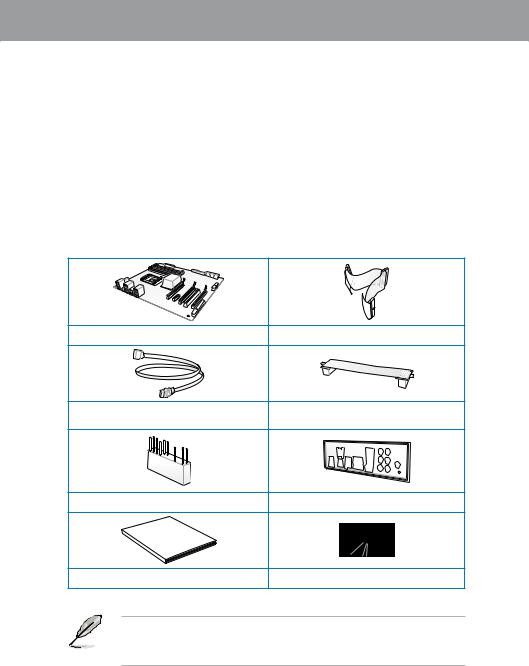
1.2Package contents
Check your motherboard package for the following items.
ASUS M4N98TD EVO motherboard |
1 x Ultra DMA 133/100 cable |
4 x Serial ATA cables |
1 x ASUS SLI™ bridge connector |
1 x 2-in-1 ASUS Q-Connector kit |
1 x I/O Shield |
Manual |
|
User |
|
User guide |
Support DVD |
•If any of the above items is damaged or missing, contact your retailer.
•The illustrated items above are for reference only.Actual product specifications may vary with different models.
ASUS M4N98TD EVO |
1-1 |

1 Chapter
1.3Special features
1.3.1Product highlights
AMD® Phenom™ II / Athlon™ II / Sempron™ 100 Series Processors (socket AM3)
This motherboard supports AMD® AM3 multi-core processors with unique L3 cache and delivers better overclocking capabilities with less power consumption. It features dual-channel DDR3 1333 memory support and accelerates data transfer rate up to 5200MT/s via HyperTransport™ 3.0 based system bus. This motherboard also supports AMD® CPUs in the new 45nm manufacturing process.
NVIDIA nForce® 980a SLI® chipset
NVIDIA nForce® 980a SLI® media and communication processors (MCPs) power the most feature-rich, high performance motherboards for AMD AM3 CPUs. The MCPs support the NVIDIA® Scalable Link Interface (SLI) technology that allows two graphics processing units (GPUs) in a single system. The NVIDIA nFORCE® 980a SLI® chipset also supports six Serial ATA 3.0 Gb/s devices, PCI Express x16 slots with NVIDIA® SLI™ support at dual x16 mode, and up to 12 USB 2.0 ports.
DDR3 2000(O.C.) support
This motherboard supports DDR3 2000(O.C.), which provides faster data transfer rate and more bandwidth to increase memory data transfer rate and computing efficiency. This enhances system performance in 3D graphics and other memory demanding applications.
NVIDIA® SLI® Technology support
NVIDIA SLI® (Scalable Link Interface) makes use of the PCI Express 2.0 bus architecture´s increased bandwidth and features intelligent hardware and software that allows two GPUs to efficiently work together to deliver earth-shattering, scalable performance. For some applications, this translates into nearly double the performance!
NVIDIA® Hybrid SLI™
Hybrid SLI™ technology is a unique hybrid multi-GPU technology built upon NVIDIA. Hybrid SLI™ turbo-charges performance of NVIDIA discrete graphics cards when combined with this series motherboard GPUs. Hybrid SLI™ is independent on selected GeForce® GPUs. Refer to www.nvidia.com/hybridsli for more information.
1-2 |
Chapter 1: Product Introduction |

1.3.2ASUS unique features
ASUS Power Solutions
ASUS power solutions intelligently and automatically provide balanced computing power and energy consumption.
8+1 Phase Power Design
To fully unleash the next-generation AM3 CPU’s potential, the ASUS M4N98TD EVO motherboard has adopted a brand new 8-phase VRM power design. It delivers high power efficiency and supreme overclocking ability. Furthermore, high quality power components can effectively lower system temperature to ensure longer component lifespan. This series also features an extra 1 phase power dedicated to integrated memory/HT controller.
100% Long-Life Solid Cap.
This motherboard uses all long-life capacittors onboard for durability, imporved lifespan, and enhanced thermal capacity.
ASUS EPU
The ASUS EPU (Energy Processing Unit) provides total system power management by detecting current PC loadings and intelligently moderating power usage for critical PC components in real-time–helping save power and money! Refer to page 4-6 for details.
ASUS Quiet Thermal Solutions
ASUS Quiet Thermal solutions make the system more stable and enhance the overclocking capability.
ASUS Fanless Design–Heat pipe solution
The Heat Pipe design effectively directs the heat generated by the chipsets to the heatsink near the back IO ports, where it can be carried away by existing airflow from
CPU fan. The purpose of the innovative heat pipe design on this motherboard is that the groundbreaking fanless design does not have lifetime problems as a chipset fan does. Furthermore, it provides options for users to install side-flow fan or passive cooler. The Heat Pipe design is the most reliable fanless thermal solution to date.
DO NOT uninstall the heat pipe by yourself. Doing so may bend the tubing and affect the heat dissipation performance.
Up to 20ºC (36ºF) Cooler—Stack Cool 3+
Stack Cool 3+ is a fanless cooling solution offered exclusively by ASUS. It effectively and noiselessly transfers heat generated by the critical components to the other side of the specially designed PCB (printed circuit board) for effective heat dissipation— making temperatures cooler by up to 20ºC.
Fan Xpert
ASUS Fan Xpert intelligently allows you to adjust both the CPU and chassis fan speeds according to different ambient temperatures caused by different climate conditions
in different geographic regions and your PC’s loading. The built-in variety of useful profiles offer flexible controls of fan speed to achieve a quiet and cool environment.
Refer to page 4-5 for details.
Chapter 1
ASUS M4N98TD EVO |
1-3 |

1 Chapter
ASUS Exclusive Features
Core Unlocker
ASUS Core Unlocker simplifies the activation of a latentAMD® CPU—with just a simple switch or hot key. Enjoy an instant performance boost by simply unlocking the extra cores, without performing complicated BIOS changes. Refer to page 2-21 for details.
MemOK!
Memory compatibility is among the top concerns during computer upgrades. Worry no more. MemOK! is the fastest memory booting solution today. This remarkable memory rescue tool requires nothing but a push of a button to patch memory issues and get your system up and running in no time. The technology is able to determine failsafe settings that can dramatically improve your system booting success. Refer to page 2-20 for details.
ASUS exclusive overclocking features
TurboV
Feel the adrenaline rush of real-time OC—now a reality with the ASUS TurboV. This easy OC tool allows you to overclock without exiting or rebooting the OS; and its userfriendly interface makes overclock with just a few clicks away. Moreover, the ASUS OC profiles in TurboV provides the best O.C. settings in different scenarios. Refer to page
4-10 for details.
Turbo Key
ASUS Turbo Key allows the user to turn the PC power button into a physical overclocking button. After the easy setup, Turbo Key can boost performances without interrupting ongoing work or games—with just one touch! Refer to page 4-11 for details.
Express Gate
Express Gate is an ASUS exclusive OS that provides you with quick access to the Internet and key applications before entering the Windows® OS. Refer to pages 3-30 and 4-7 for details.
ASUS EZ DIY
ASUS EZ DIY feature collection provides you easy ways to install computer components, update the BIOS or back up your favorite settings.
ASUS Q-Connector
ASUS Q-Connector allows you to easily connect or disconnect the chassis front panel cables to the motherboard. This unique module eliminates the trouble of connecting the system panel cables one at a time and avoiding wrong cable connections.
ASUS O.C. Profile
The motherboard features theASUS O.C. Profile that allows users to conveniently store or load multiple BIOS settings. The BIOS settings can be stored in the CMOS or a separate file, giving users freedom to share and distribute their favorite settings.
ASUS EZ Flash 2
ASUS EZ Flash 2 is a user-friendly BIOS update utility. Simply press the predefined hotkey to launch the utility and update the BIOS without entering the OS. Update your
BIOS easily without preparing a bootable diskette or using an OS-based flash utility.
1-4 |
Chapter 1: Product Introduction |
Chapter 2
Chapter 2: |
Hardware information |
2.1Before you proceed
Take note of the following precautions before you install motherboard components or change any motherboard settings.
•Unplug the power cord from the wall socket before touching any component.
• Before handling components, use a grounded wrist strap or touch a safely grounded object or a metal object, such as the power supply case, to avoid damaging them due to static electricity.
•Hold components by the edges to avoid touching the ICs on them.
•Whenever you uninstall any component, place it on a grounded antistatic pad or in the bag that came with the component.
•Before you install or remove any component, ensure that the ATX power supply is switched off or the power cord is detached from the power supply. Failure to do so may cause severe damage to the motherboard, peripherals, or components.
ASUS M4N98TD EVO |
2-1 |

2.2Motherboard overview
2.2.1Motherboard layout
2 Chapter
Refer to 2.8 Connectors for more information about rear panel connectors and internal connectors.
2-2 |
Chapter 2: Hardware information |
2.2.2Layout contents
Connectors/Jumpers/Slots |
Page |
|
1. |
ATX power connectors (24-pin EATXPWR, 8-pin EATX12V) |
2-31 |
2. |
AM3 CPU socket |
2-5 |
3. |
DDR3 DIMM slots |
2-10 |
4. |
CPU, chassis, and power fan connectors (4-pin CPU_FAN, |
2-30 |
|
4-pin CHA_FAN1, 3-pin CHA_FAN2, 3-pin PWR_FAN) |
|
|
|
|
5. |
Core Unlocker switch (CORE_UNLOCKER) |
2-21 |
6. |
MemOK! switch |
2-20 |
7. |
IDE connector (40-1 pin PRI_IDE) |
2-26 |
8. |
CPU overvoltage setting (3-pin OV_CPU) |
2-19 |
9. |
Clear RTC RAM (3-pin CLRTC) |
2-18 |
10. |
Serial ATA connectors (7-pin SATA1–5) |
2-27 |
11. |
Standby Power LED |
2-35 |
12. |
System panel connector (20-8 pin PANEL) |
2-33 |
13. |
USB connectors (10-1 pin USB78, USB910, USB1112) |
2-28 |
14. |
Serial port connector (10-1 pin COM1) |
2-29 |
15. |
IEEE 1394a port connector (10-1 pin IE1394_2) |
2-29 |
16. |
Digital audio connector (4-1 pin SPDIF_OUT) |
2-32 |
17. |
Front panel audio connector (10-1 pin AAFP) |
2-32 |
Chapter 2
ASUS M4N98TD EVO |
2-3 |
2 Chapter
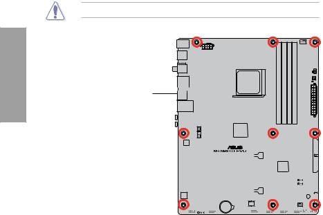
2.2.3Placement direction
When installing the motherboard, ensure that you place it into the chassis in the correct orientation. The edge with external ports goes to the rear part of the chassis as indicated in the image below.
2.2.4Screw holes
Place nine screws into the holes indicated by circles to secure the motherboard to the chassis.
DO NOT overtighten the screws! Doing so can damage the motherboard.
Place this side towards  the rear of the chassis
|
|
|
|
|
|
|
|
|
|
|
|
|
|
|
|
|
|
|
|
|
|
|
|
|
|
|
|
|
|
|
|
|
|
|
|
|
|
|
|
|
|
|
|
|
|
|
|
|
|
|
|
|
|
|
|
|
|
|
|
|
|
|
|
|
|
|
|
|
|
|
|
|
|
|
|
|
|
|
|
|
|
|
|
|
|
|
|
|
|
|
|
|
|
|
|
|
|
|
|
|
|
|
|
|
|
|
|
|
|
|
|
|
|
|
|
|
|
|
|
|
|
|
|
|
|
|
|
|
|
|
|
|
|
|
|
|
|
|
|
|
|
|
|
|
|
|
|
|
|
|
|
|
|
|
|
|
|
|
|
|
|
|
|
|
|
|
|
|
|
|
|
|
|
|
|
|
|
|
|
|
|
|
|
|
|
|
|
|
|
|
|
|
|
|
|
|
|
|
|
|
|
|
|
|
|
|
|
|
|
|
|
|
|
|
|
|
|
|
|
|
|
|
|
|
|
|
|
|
|
|
|
|
|
|
|
|
|
|
|
|
|
|
|
|
|
|
|
|
|
|
|
|
|
|
|
|
|
|
|
|
|
|
|
|
|
|
|
|
|
|
|
|
|
|
|
|
|
|
|
|
|
|
|
|
|
|
|
|
|
|
|
|
|
|
|
|
|
|
|
|
|
|
|
|
|
|
|
|
|
|
|
|
|
|
|
|
|
|
|
|
|
|
|
|
|
|
|
|
|
|
|
|
|
|
|
|
|
|
|
|
|
|
|
|
|
|
|
|
|
|
|
|
|
|
|
|
|
|
|
|
|
|
|
|
|
|
|
|
|
|
|
|
|
|
|
|
|
|
|
|
|
|
|
|
|
|
|
|
|
|
|
|
|
|
|
|
|
|
|
|
|
|
|
|
|
|
|
|
|
|
|
|
|
|
|
|
|
|
|
|
|
|
|
|
|
|
|
|
|
|
|
|
|
|
|
|
|
|
|
|
|
|
|
|
|
|
|
|
|
|
|
|
|
|
|
|
|
|
|
|
|
|
|
|
|
|
|
|
|
|
|
|
|
|
|
|
|
|
|
|
|
|
|
|
|
|
|
|
|
|
|
|
|
|
|
|
|
|
|
|
|
|
|
|
|
|
|
|
|
|
|
|
|
|
|
|
|
|
|
|
|
|
|
|
|
|
|
|
|
|
|
|
|
|
|
|
|
|
|
|
|
|
|
|
|
|
|
|
|
|
|
|
|
|
|
|
|
|
|
|
|
|
|
|
|
|
|
|
|
|
|
|
|
|
|
|
|
|
|
|
|
|
|
|
|
|
|
|
|
|
|
|
|
|
|
|
|
|
|
|
|
|
|
|
|
|
|
|
|
|
|
|
|
|
|
|
|
|
|
|
|
|
|
|
|
|
|
|
|
|
|
|
|
|
|
|
|
|
|
|
|
|
|
|
|
|
|
|
|
|
|
|
|
|
|
|
|
|
|
|
|
|
|
|
|
|
|
|
|
|
|
|
|
|
|
|
|
|
|
|
|
|
|
|
|
|
|
|
|
|
|
|
|
|
|
|
|
|
|
|
|
|
|
|
|
|
|
|
|
|
|
|
|
|
|
|
|
|
|
2-4 |
|
|
|
|
|
|
|
|
|
|
|
Chapter 2: Hardware information |
|||||||||||||||||
2.3Central Processing Unit (CPU)
The motherboard comes with an AM3 socket designed for AMD® Phenom™ II / Athlon™ II / Sempron™ 100 Series Processors.
Ensure that all power cables are unplugged before installing the CPU.
The AM3 socket has a different pinout from the 940-pin socket designed for the AMD
Opteron processor. Ensure that you use a CPU designed for theAM3 socket. The CPU fits in only one correct orientation. DO NOT force the CPU into the socket to prevent bending the connectors on the socket and damaging the CPU!
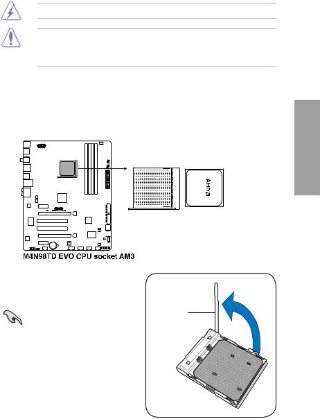
2.3.1Installing the CPU
To install a CPU:
1.Locate the CPU socket on the motherboard.
2. Unlock the socket by pressing the lever sideways, then lift it up to a 90º angle.
|
Socket lever |
|
Ensure that the socket lever is lifted |
||
|
||
up to a 90º angle; otherwise, the CPU |
|
|
will not fit in completely. |
|
|
|
|
Chapter 2
ASUS M4N98TD EVO |
2-5 |
2 Chapter
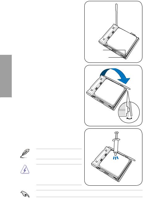
3.Position the CPU above the socket such that the CPU corner with the gold triangle matches the socket corner with a small triangle.
4.Carefully insert the CPU into the socket until it fits in place.
Gold triangle
Small triangle
5.When the CPU is in place, push down the socket lever to secure the CPU. The lever clicks on the side tab to indicate that it is locked.
6.Apply some Thermal Interface Material to the exposed area of the CPU that the heatsink will be in contact with, ensuring that it is spread in an even thin layer.
Some heatsinks come with pre-applied thermal paste. If so, skip this step.
The Thermal Interface Material is toxic and inedible. If it gets into your eyes or touches your skin, wash it off immediately, and seek professional medical help.
To prevent contaminating the paste, DO NOT spread the paste with your finger.
2-6 |
Chapter 2: Hardware information |
2.3.2Installing the CPU heatsink and fan
The AMD® AM3 processor requires a specially designed heatsink and fan assembly to ensure optimum thermal condition and performance.
Ensure that you use onlyAMD-certified heatsink and fan assembly.
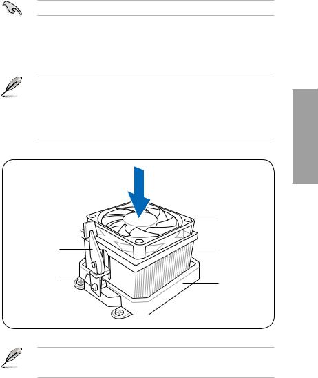
To install the CPU heatsink and fan:
1.Place the heatsink on top of the installed CPU, ensuring that the heatsink fits properly on the retention module base.
• The retention module base is already installed on the motherboard upon purchase.
• You do not have to remove the retention module base when installing the CPU or installing other motherboard components.
•If you purchased a separate CPU heatsink and fan assembly, ensure that a Thermal Interface Material is properly applied to the CPU heatsink or CPU before you install the heatsink and fan assembly.
|
CPU fan |
|
Retention bracket |
CPU heatsink |
|
lock |
||
|
||
Retention bracket |
Retention module |
|
|
base |
Your boxed CPU heatsink and fan assembly should come with installation instructions for the CPU, heatsink, and the retention mechanism. If the instructions in this section do not match the CPU documentation, follow the latter.
Chapter 2
ASUS M4N98TD EVO |
2-7 |
2 Chapter
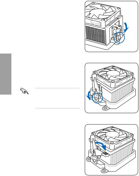
2.Attach one end of the retention bracket to the retention module base.
3.Align the other end of the retention bracket (near the retention bracket lock) to the retention module base. A clicking sound denotes that the retention bracket is in place.
Ensure that the fan and heatsink assembly perfectly fits the retention mechanism module base, otherwise you cannot snap the retention bracket in place.
4.Push down the retention bracket lock on the retention mechanism to secure the heatsink and fan to the module base.
2-8 |
Chapter 2: Hardware information |
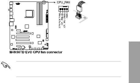
5.When the fan and heatsink assembly is in place, connect the CPU fan cable to the connector on the motherboard labeled CPU_FAN.
•
•
Do not forget to connect the CPU fan connector! Hardware monitoring errors can occur if you fail to plug this connector.
This connector is backward compatible with old 3-pin CPU fan.
Chapter 2
ASUS M4N98TD EVO |
2-9 |
2.4System memory
2.4.1Overview
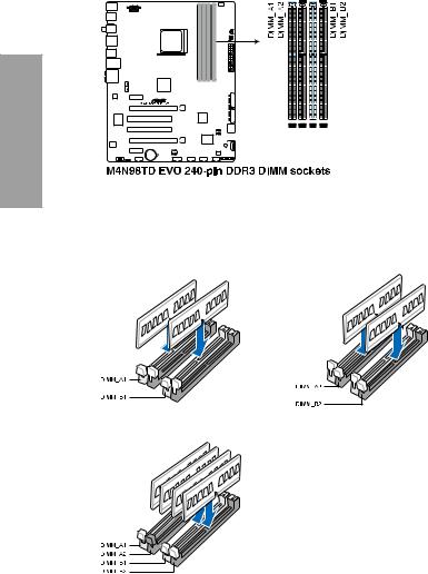
The motherboard comes with four Double Data Rate 3 (DDR3) Dual Inline Memory Modules (DIMM) sockets.
A DDR3 module has the same physical dimensions as a DDR2 DIMM but is notched differently to prevent installation on a DDR2 DIMM socket. DDR3 modules are developed for better performance with less power consumption.
The figure illustrates the location of the DDR3 DIMM sockets:
2 Chapter
Recommended memory configurations
One DIMM:
You may install one memory module in any slot as a single-channel operation.
Two DIMMs (dual-channel operation):
Four DIMMs (dual-channel operation):
2-10 |
Chapter 2: Hardware information |

2.4.2Memory configurations
You may install 1GB, 2GB and 4GB unbuffered ECC and non ECC DDR3 DIMMs into the DIMM sockets.
•You may install varying memory sizes in ChannelAand Channel B. The system maps the total size of the lower-sized channel for the dual-channel configuration.Any excess memory from the higher-sized channel is then mapped for single-channel operation.
•We recommend that you install the memory modules from the blue slots for better overclocking capability.
•Always install DIMMs with the same CAS latency. For optimum compatibility, it is recommended that you obtain memory modules from the same vendor.
•Due to the memory address limitation on 32-bit Windows OS, when you install 4GB or more memory on the motherboard, the actual usable memory for the OS can be about 3GB or less. For effective use of memory, we recommend that you do any of the following:
-Use a maximum of 3GB system memory if you are using a 32-bit Windows OS.
-Install a 64-bit Windows OS when you want to install 4GB or more on the motherboard.
For more details, refer to the Microsoft® support site at http://support.microsoft.com/kb/929605/en-us.
•This motherboard does not support DIMMs made up of 512Mb (64MB) chips or less (Memory chip capacity counts in Megabit, 8 Megabit/Mb = 1 Megabyte/MB).
•The default memory operation frequency is dependent on its Serial Presence Detect (SPD), which is the standard way of accessing information from a memory module. Under the default state, some memory modules for overclocking may operate at a lower frequency than the vendor-marked value. To operate at the vendor-marked or at a higher frequency, see section 3.5 Ai Tweaker menu for manual memory frequency adjustment.
•For system stability, use a more efficient memory cooling system to support a full memory load (4 DIMMs) or overclocking condition.
Chapter 2
ASUS M4N98TD EVO |
2-11 |

2 Chapter
M4N98TD EVO Motherboard Qualified Vendors Lists (QVL)
DDR3-1600 MHz capability
Vendor |
Part No. |
Size |
SS/DS |
Chip |
Chip |
Timing |
Voltage |
DIMM socket support |
||
(Optional) |
|
|||||||||
|
|
|
|
Brand |
NO. |
|
|
|
|
|
|
|
|
|
|
|
1 DIMM |
2 DIMM |
4 DIMM |
||
|
|
|
|
|
|
|
|
|||
A-DATA |
AD31600E001GMU |
3GB(3 x 1GB) |
SS |
- |
- |
8-8-8-24 |
1.65-1.85 |
• |
• |
• |
A-DATA |
AD31600F002GMU(XMP) |
6GB(3 x 2GB) |
DS |
- |
- |
7-7-7-20 |
1.75-1.85 |
|
|
• |
CORSAIR |
CMG4GX3M2A1600C6 |
4GB( 2x 2GB ) |
DS |
- |
- |
6-6-6-18 |
1.65 |
• |
• |
• |
CORSAIR |
CMD4GX3M2A1600C8(XMP) |
4GB(2 x 2GB) |
DS |
- |
- |
8-8-8-24 |
1.65 |
|
|
• |
Crucial |
BL12864BA1608.8SFB(XMP) |
1GB |
SS |
- |
- |
- |
1.8 |
• |
• |
• |
Crucial |
BL25664BN1608.16FF(XMP) |
2GB |
DS |
- |
- |
8-8-8-24 |
1.65 |
• |
• |
• |
G.SKILL |
F3-12800CL9D-2GBNQ |
2GB(2 x 1GB) |
SS |
- |
- |
- |
1.6 |
• |
|
|
G.SKILL |
F3-12800CL7D-4GBRH(XMP) |
4GB(2 x 2GB) |
DS |
- |
- |
7-7-7-24 |
1.65 |
• |
• |
• |
KINGMAX |
FLGD45F-B8MF7(XMP) |
1GB |
SS |
- |
- |
|
- |
• |
• |
• |
KINGMAX |
FLGE85F-B8MF7(XMP) |
2GB |
DS |
- |
- |
|
- |
|
|
• |
KINGSTON |
KHX1600C9D3K3/12GX(XMP) |
12GB(3 x 4GB) |
DS |
- |
- |
- |
1.65 |
• |
• |
• |
KINGSTON |
KHX1600C9D3K3/12GX(XMP) |
12GB(3 x 4GB) |
DS |
- |
- |
9 |
1.65 |
• |
• |
• |
OCZ |
OCZ3P1600LV3GK |
3GB(3 x 1GB) |
SS |
- |
- |
7-7-7 |
1.65 |
|
|
• |
Super Talent |
WP160UX4G8(XMP) |
4GB(2 x 2GB) |
DS |
- |
- |
8 |
- |
|
|
• |
Super Talent |
WP160UX4G9(XMP) |
4GB(2 x 2GB) |
DS |
- |
- |
9 |
- |
• |
• |
• |
M4N98TD EVO Motherboard Qualified Vendors Lists (QVL)
DDR3-1333 MHz capability
Vendor |
Part No. |
Size |
SS/ |
Chip |
Chip NO. |
Timing |
Voltage |
DIMM socket support |
||
(Optional) |
|
|||||||||
|
|
|
DS |
Brand |
|
|
|
|
|
|
|
|
|
|
|
|
1 DIMM |
2 DIMM |
4 DIMM |
||
|
|
|
|
|
|
|
|
|||
A-DATA |
AD3133301GOU |
1GB |
SS |
A-DATA |
AD30908C8D-15IG |
- |
- |
• |
• |
• |
A-DATA |
AX3U1333PB2G7-2P |
4GB(2 x 2GB) |
DS |
- |
- |
7-7-7-20 |
1.65-1.85 |
• |
• |
• |
A-DATA |
AD31333E002G0U |
6GB(3 x 2GB) |
DS |
- |
- |
7-7-7-20 |
1.65-1.85 |
• |
• |
• |
A-DATA |
AX3U1333PB2G7-3P |
6GB(3 x 2GB) |
DS |
- |
- |
7-7-7-20 |
1.65-1.85 |
• |
• |
• |
Apacer |
78.A1GC6.9L1 |
2GB |
DS |
Apacer |
AM5D5808DEWSBG |
9 |
- |
• |
• |
|
CORSAIR |
TR3X3G1333C9 (Ver2.1) |
3GB(3 x 1GB) |
SS |
- |
- |
9-9-9-24 |
1.5 |
• |
• |
• |
CORSAIR |
BoxP/N:TWIN3X2048-1333C9 |
2GB(2 x 1GB) |
DS |
- |
- |
9-9-9-24 |
1.70 |
|
|
• |
(CM3X1024-1333C9)Ver1.1 |
|
|
||||||||
Crucial |
CT12864BA1339.8SFD |
1GB |
SS |
MICRON |
MT8JF12864AY-1G4D1 |
- |
- |
• |
• |
|
Crucial |
CT25664BA1339.16SFD |
2GB |
DS |
MICRON |
D9JNM |
- |
- |
• |
• |
• |
ELPIDA |
EBJ10UE8BDF0-DJ-F |
1GB |
SS |
ELPIDA |
J1108BDSE-DJ-F |
- |
- |
• |
• |
|
ELPIDA |
EBJ21UE8BDF0-DJ-F |
2GB |
DS |
ELPIDA |
J1108BDSE-DJ-F |
- |
- |
• |
• |
|
G.SKILL |
F3-10600CL8D-2GBHK |
2GB(2 x 1GB) |
SS |
- |
- |
- |
1.65 |
• |
• |
• |
G.SKILL |
F3-10666CL8D-4GBHK(XMP) |
4GB(2 x 2GB) |
DS |
- |
- |
8-8-8-21 |
1.5-1.6 |
• |
• |
|
G.SKILL |
F3-10666CL8D-4GBRM(XMP) |
4GB(2 x 2GB) |
DS |
- |
- |
8-8-8-21 |
1.5-1.6 |
• |
• |
|
G.SKILL |
F3-10666CL9T-6GBNQ |
6GB(3 x 2GB) |
DS |
- |
- |
9-9-9-24 |
1.5 |
|
|
• |
GEIL |
GG34GB1333C9DC |
4GB(2 x 2GB) |
DS |
GEIL |
GL1L128M88BA12N |
9-9-9-24 |
1.3 |
• |
• |
• |
GEIL |
GV34GB1333C7DC |
4GB(2 x 2GB) |
DS |
- |
- |
7-7-7-24 |
1.5 |
• |
• |
• |
Hynix |
HMT112U6BFR8C-H9 |
1GB |
SS |
Hynix |
H5TQ1G83BFR |
9 |
- |
• |
• |
|
Hynix |
HMT125U6BFR8C-H9 |
2GB |
DS |
Hynix |
H5TQ1G83BFRH9C |
9 |
- |
• |
• |
• |
KINGMAX |
FLFD45F-B8KG9 |
1GB |
SS |
KingMax |
KFB8FNGBF-ANX-15A |
|
- |
• |
• |
• |
KINGMAX |
FLFE85F-B8KG9 |
2GB |
DS |
KingMax |
KFB8FNGBF-ANX-15A |
|
- |
• |
• |
• |
KINGSTON |
KVR1333D3N9/1G |
1G |
SS |
Kingston |
D1288JELDPGD9U |
- |
1.5 |
• |
• |
• |
KINGSTON |
KVR1333D3N9/4G |
4GB |
DS |
SAMSUNG |
K4B2G0846B-HCH9 |
9 |
1.5 |
• |
• |
• |
MICRON |
MT8JTF12864AZ-1G4F1 |
1GB |
SS |
MICRON |
9FF22 D9KPT |
9 |
- |
• |
• |
|
MICRON |
MT16JTF25664AZ-1G4F1 |
2GB |
DS |
MICRON |
9FF22 D9KPT |
9 |
- |
|
• |
|
OCZ |
OCZ3P1333LV3GK |
3GB(3 x 1GB) |
SS |
- |
- |
7-7-7 |
1.65 |
• |
• |
• |
PSC |
AL7F8G73D-DG1 |
1GB |
SS |
PSC |
A3P1GF3DGF |
- |
- |
• |
• |
• |
PSC |
AL8F8G73D-DG1 |
2GB |
DS |
PSC |
A3P1GF3DGF |
- |
- |
• |
• |
• |
SAMSUNG |
M378B2873EH1-CH9 |
1GB |
SS |
SAMSUNG |
K4B1G0846E |
- |
- |
• |
• |
|
SAMSUNG |
M378B5673EH1-CH9 |
2GB |
DS |
SAMSUNG |
K4B1G0846E |
- |
- |
• |
• |
|
Super |
W1333UX2G8(XMP) |
2GB(2 x 1GB) |
SS |
- |
- |
8 |
1.8 |
• |
• |
• |
Talent |
||||||||||
|
|
|
|
|
|
|
|
|
|
|
2-12 |
Chapter 2: Hardware information |
 Loading...