


A7N8X
User Guide
Motherboard

E1859
Revised V4
January 2005
Copyright © 2005 ASUSTeK COMPUTER INC. All Rights Reserved.
No part of this manual, including the products and software described in it, may be reproduced, transmitted, transcribed, stored in a retrieval system, or translated into any language in any form or by any means, except documentation kept by the purchaser for backup purposes, without the express written permission of ASUSTeK COMPUTER INC. (“ASUS”).
Product warranty or service will not be extended if: (1) the product is repaired, modified or altered, unless such repair, modification of alteration is authorized in writing by ASUS; or (2) the serial number of the product is defaced or missing.
ASUS PROVIDES THIS MANUAL “AS IS” WITHOUT WARRANTY OF ANY KIND, EITHER EXPRESS OR IMPLIED, INCLUDING BUT NOT LIMITED TO THE IMPLIED WARRANTIES OR CONDITIONS OF MERCHANTABILITY OR FITNESS FOR A PARTICULAR PURPOSE. IN NO EVENT SHALL ASUS, ITS DIRECTORS, OFFICERS, EMPLOYEES OR AGENTS BE LIABLE FOR ANY INDIRECT, SPECIAL, INCIDENTAL, OR CONSEQUENTIAL DAMAGES (INCLUDING DAMAGES FOR LOSS OF PROFITS, LOSS OF BUSINESS, LOSS OF USE OR DATA, INTERRUPTION OF BUSINESS AND THE LIKE), EVEN IF ASUS HAS BEEN ADVISED OF THE POSSIBILITY OF SUCH DAMAGES ARISING FROM ANY DEFECT OR ERROR IN THIS MANUAL OR PRODUCT.
SPECIFICATIONS AND INFORMATION CONTAINED IN THIS MANUAL ARE FURNISHED FOR INFORMATIONAL USE ONLY, AND ARE SUBJECT TO CHANGE AT ANY TIME WITHOUT NOTICE, AND SHOULD NOT BE CONSTRUED AS A COMMITMENT BY ASUS. ASUS ASSUMES NO RESPONSIBILITY OR LIABILITY FOR ANY ERRORS OR INACCURACIES THAT MAY APPEAR IN THIS MANUAL, INCLUDING THE PRODUCTS AND SOFTWARE DESCRIBED IN IT.
Products and corporate names appearing in this manual may or may not be registered trademarks or copyrights of their respective companies, and are used only for identification or explanation and to the owners’ benefit, without intent to infringe.
ii

Contents
Contents |
......................................................................................... |
iii |
FCC/CDC statements ...................................................................... |
v |
|
Federal Communications Commission Statement ................. |
v |
|
Canadian Department of Communications Statement ........... |
v |
|
Safety information .......................................................................... |
vi |
|
About this guide............................................................................. |
vii |
|
Conventions used in this guide ............................................ |
vii |
|
Where to find more information ............................................ |
vii |
|
ASUS contact information ............................................................. |
vii |
|
Specifications summary ................................................................. |
ix |
|
Chapter 1 - Motherboard Info ................................................... |
1-1 |
|
1.1 |
Welcome ...................................................................... |
1-2 |
1.2 |
Package contents ....................................................... |
1-2 |
1.3 |
Motherboard components .......................................... |
1-3 |
1.4 |
Motherboard layout..................................................... |
1-6 |
1.5 |
Before you proceed..................................................... |
1-7 |
1.6 |
Central Processing Unit (CPU)................................... |
1-7 |
1.7 |
System memory........................................................... |
1-8 |
1.8 |
Expansion Slots........................................................... |
1-8 |
1.8.1 Configuring an expansion card .................................. |
1-9 |
|
1.8.2 Standard Interrupt Assignments ................................ |
1-9 |
|
1.8.3 AGP Slot ........................................................ |
1-9 |
|
1.9 |
Jumpers ....................................................................... |
1-10 |
1.10 Connectors ................................................................. |
1-13 |
|
Chapter 2 - BIOS Information ..................................................... |
.2-1 |
|
2.1 Managing and updating your BIOS ............................ |
2-2 |
|
2.1.1 Using ASUS AWDFLASH to update the BIOS................ |
2-2 |
|
2.1.2 Using ASUS AWDFLASH to update the BIOS.................. |
2-3 |
|
|
Updating BIOS procedures.................................... |
2-3 |
2.2 |
BIOS Setup Program ................................................... |
2-6 |
2.2.1 BIOS menu bar ........................................................... |
2-7 |
|
2.2.2 Legend bar .................................................................. |
2-7 |
|
iii

Contents
2.3 |
Main Menu .................................................................... |
2-9 |
2.3.1 Primary Master/Slave .......................................... |
2-10 |
|
2.3.2 Secondary Master/Slave................................................ |
2-12 |
|
2.4 Advanced Menu ........................................................... |
2-13 |
|
2.4.1 Advanced BIOS Configuration ...................................... |
2-14 |
|
2.4.2 Advanced Chipset Features........................................... |
2-15 |
|
2.4.3 Integrated Peripherals..................................................... |
2-18 |
|
2.4.4 Power Management Setup ........................................ |
2-20 |
|
2.4.5 PnP/PCI Configurations ........................................ |
2-22 |
|
2.5 Security Menu.................................................................. |
2-23 |
|
2.5.1 Supervisor/User Set Password Table............................ |
2-23 |
|
2.5.2 User Set Password only ................................................ |
2-23 |
|
2.6 Hardware Monitor Menu ................................................ |
2-24 |
|
2.7 Exit Menu ................................................................. |
2-26 |
|
Chapter 3 - Starting Up .............................................................. |
3-1 |
|
3.1 Install an operating system......................................... |
3-2 |
|
3.2 Support CD information.............................................. |
3-2 |
|
3.2.1 Running the support CD ............................................ |
3-2 |
|
3.2.2 Software drivers and installation menus .................... |
3-3 |
|
iv

FCC/CDC statements
Federal Communications Commission Statement
This device complies with FCC Rules Part 15. Operation is subject to the following two conditions:
•This device may not cause harmful interference, and
•This device must accept any interference received including interference that may cause undesired operation.
This equipment has been tested and found to comply with the limits for a Class B digital device, pursuant to Part 15 of the FCC Rules. These limits are designed to provide reasonable protection against harmful interference in a residential installation. This equipment generates, uses and can radiate radio frequency energy and, if not installed and used in accordance with manufacturer’s instructions, may cause harmful interference to radio communications. However, there is no guarantee that interference will not occur in a particular installation. If this equipment does cause harmful interference to radio or television reception, which can be determined by turning the equipment off and on, the user is encouraged to try to correct the interference by one or more of the following measures:
•Reorient or relocate the receiving antenna.
•Increase the separation between the equipment and receiver.
•Connect the equipment to an outlet on a circuit different from that to which the receiver is connected.
•Consult the dealer or an experienced radio/TV technician for help.
The use of shielded cables for connection of the monitor to the graphics card is required to assure compliance with FCC regulations. Changes or modifications to this unit not expressly approved by the party responsible for compliance could void the user’s authority to operate this equipment.
Canadian Department of Communications Statement
This digital apparatus does not exceed the Class B limits for radio noise emissions from digital apparatus set out in the Radio Interference Regulations of the Canadian Department of Communications.
This class B digital apparatus complies with Canadian ICES-003.
v

Safety information
Electrical safety
•To prevent electrical shock hazard, disconnect the power cable from the electrical outlet before relocating the system.
•When adding or removing devices to or from the system, ensure that the power cables for the devices are unplugged before the signal cables are connected. If possible, disconnect all power cables from the existing system before you add a device.
•Before connecting or removing signal cables from the motherboard, ensure that all power cables are unplugged.
•Seek professional assistance before using an adpater or extension cord. These devices could interrupt the grounding circuit.
•Make sure that your power supply is set to the correct voltage in your area. If you are not sure about the voltage of the electrical outlet you are using, contact your local power company.
•If the power supply is broken, do not try to fix it by yourself. Contact a qualified service technician or your retailer.
Operation safety
•Before installing the motherboard and adding devices on it, carefully read all the manuals that came with the package.
•Before using the product, make sure all cables are correctly connected and the power cables are not damaged. If you detect any damage, contact your dealer immediately.
•To avoid short circuits, keep paper clips, screws, and staples away from connectors, slots, sockets and circuitry.
•Avoid dust, humidity, and temperature extremes. Do not place the product in any area where it may become wet.
•Place the product on a stable surface.
•If you encounter technical problems with the product, contact a qualified service technician or your retailer.
vi

Conventions used in this guide
To make sure that you perform certain tasks properly, take note of the following symbols used throughout this manual.
WARNING/DANGER: Information to prevent injury to yourself when trying to complete a task.
CAUTION: Information to prevent damage to the components when trying to complete a task.
IMPORTANT: Information that you MUST follow to complete a task.
NOTE: Tips and additional information to aid in completing a task.
Where to find more information
Refer to the following sources for additional information and for product and software updates.
1.ASUS Websites
The ASUS websites worldwide provide updated information on ASUS hardware and software products. The ASUS websites are listed in the ASUS Contact Information on page viii.
2.Optional Documentation
Your product package may include optional documentation, such as warranty flyers, that may have been added by your dealer. These documents are not part of the standard package.
vii

ASUS contact information
ASUSTeK COMPUTER INC. (Asia-Pacific)
Address |
15 Li-Te Road, Peitou, Taipei, Taiwan 112 |
Telephone |
+886-2-2894-3447 |
Web site |
www.asus.com.tw |
Technical Support |
|
Telephone(MB/Component) |
+886-2-2890-7121 (English) |
(Notebook) |
+886-2-2890-7122 (English) |
(Server/PC) |
+886-2-2890-7123 (English) |
(Networking) |
+886-2-2890-7902 (English) |
Support fax |
+886-2-2890-7698 |
ASUS COMPUTER INTERNATIONAL (America)
Address |
44370 Nobel Drive, Fremont, CA 94538, USA |
Fax |
+1-510-608-4555 |
tmd1@asus.com |
|
Web site |
usa.asus.com |
Technical Support |
|
Telephone (General) |
+1-502-995-0883 |
(Notebook) |
+1-510-739-3777 |
Support fax |
+1-502-933-8713 |
Support e-mail |
tsd@asus.com |
ASUS COMPUTER GmbH (Germany and Austria)
Address |
Harkort Str. 25, D-40880 Ratingen, Germany |
Telephone |
+49-2102-95990 |
Fax |
+49-2102-959911 |
Online contact |
www.asuscom.de/sales |
Technical Support |
|
Telephone |
+49-2102-95990 |
Fax |
+49-2102-959911 |
Online support |
www.asuscom.de/support |
Web site |
www.asuscom.de/news |
viii

A7N8X specifications summary
CPU |
Socket A for AMD Duron™/Athlon™/Athlon™ XP 3000+ or |
|
|
higher |
|
|
400*/333 MHz FSB Support (*PCB 2.0 or later versions) |
|
Chipset |
|
|
Northbridge: NVIDIA® nForce2 SPP (Ultra 400) |
||
|
Southbridge: NVIDIA® nForce2 MCP |
|
Front Side Bus (FSB) |
400*/333/266/200Mhz (*PCB 2.0 or later versions) |
|
Memory |
|
|
3 x 184-pin DDR DIMM Sockets |
||
|
Max. 3 GB unbuffered PC3200/2700/2100/1600 non-ECC |
|
|
DDR RAM memory. Dual-Channel DDR400 support. |
|
|
(Visit ASUS website for latest qualified DDR400 module list.) |
|
Expansion slots |
|
|
5 x PCI |
||
|
1 x AGP Pro/8X (1.5V only) |
|
IDE |
|
|
2 x UltraDMA 133/100/66/33 |
||
Audio (optional) |
|
|
Realtek ALC650 6CH with built-in HP amplifier |
||
LAN (optional) |
|
|
1 Port |
||
|
MCP integrated NVIDIA MAC + Realtek 8201BL PHY |
|
Special Features |
|
|
ASUS Q-Fan Technology |
||
|
ASUS C.O.P. (CPU Overheating Protection) |
|
|
Power Loss Restart |
|
|
CPU Throttle |
|
|
Support S/PDIF in/out (optional) |
|
Back Panel I/O Ports |
|
|
1 x Parallel |
||
|
1 x Serial |
|
|
1 x PS/2 Keyboard |
|
|
1 x PS/2 Mouse |
|
|
1 x RJ45 port |
|
|
1 x Audio I/O |
|
|
4 x USB 2.0 |
|
Internal I/O |
|
|
1 x USB 2.0 connector supports additional 2 USB 2.0 ports |
||
Connectors |
(optional) |
|
|
Game connector |
|
|
CPU/Power/Chassis FAN connectors |
|
|
20-pin ATX Power connector |
|
|
IDE LED connector, Power LED connector |
|
|
Chassis Intrusion, SM Bus, SIR |
|
|
Headphone (optional) |
|
|
Front MIC (optional) |
|
|
CD / AUX / Modem audio in |
|
|
Front Panel Audio connector (optional) |
|
|
|
|
|
(continued on the next page) |
|
ix

A7N8X specifications summary
BIOS features |
2Mb Flash ROM, Award BIOS, TCAV, PnP, DMI2.0, DMI, |
|
|
Green |
|
|
|
|
Industry standard |
PCI 2.2, USB 1.1/2.0. |
|
|
|
|
Manageability |
DMI 2.0, WOL, WOR, Chassis Intrusion, SM Bus |
|
|
|
|
Support CD contents |
Device drivers |
|
|
ASUS PC Probe |
|
|
Anti-virus utility |
|
|
ASUS LiveUpdate Utility |
|
|
|
|
Accessories |
User’s manual |
|
|
Support CD |
|
|
1 x UltraDMA 33 cable |
|
|
1 x UltraDMA 133/100/66 cable |
|
|
FDD cable |
|
|
9-pin COM cable |
|
|
2-port USB/Game port bracket (optional) |
|
|
I/O shield |
|
|
|
|
Form Factor |
ATX form factor: 12 in x 9.6 in |
|
|
|
|
* Specifications are subject to change without notice.
x
Chapter 1
This chapter gives information about the ASUS A7N8X motherboard that came with the system.This chapter includes the motherboard layout, jumper settings, and connector locations.
Motherboard Info
ASUS A7N8X Motherboard |
1-1 |

1.1Welcome!
Thank you for buying the ASUS® A7N8X motherboard!
The ASUS A7N8X motherboard is loaded with the most advanced technologies to deliver the maximum performance for socketAprocessors. This motherboard is loaded with value-added features for guaranteed consumer satisfaction. Unique ASUS features such as ASUS C.O.P., ASUS Q-Fan Technology and more are included to ensure the best user experience and value in a motherboard. For future upgrades or system reconfiguration, this chapter provides technical information about the motherboard.
Before you start installing the motherboard and hardware devices on it, check the items in your package with the list below.
1.2Package contents
Check your ASUS A7N8X package for the following items.
ASUS A7N8X motherboard
ATX form factor: 12 in x 9.6 in
ASUS A7N8X series support CD
40-pin 80-conductor ribbon cable for UltraDMA/66/100/133 IDE drives
Ribbon cable for a 3.5-inch floppy drive
Bag of extra jumper caps
COM2 bracket
I/O shield
User’s Manual
ASUS Game port module
ASUS 2-port USB bracket (optional)
1-2

1.3Motherboard components
1 |
2 |
3 |
4 |
5 |
19 |
|
|
6 |
|
|
|
|
18 |
|
|
|
17 |
|
|
7 |
16 |
|
|
8 |
15 |
|
|
9 |
|
|
|
|
|
|
|
10 |
|
|
|
11 |
14 |
|
|
|
|
|
13 |
12 |
20 |
|
21 |
22 |
|
|
|
23 |
|
|
|
24 |
|
|
|
25 |
29 |
28 |
27 |
26 |
ASUS A7N8X Motherboard |
1-3 |

1CPU Sockets. Socket 462 (Socket A) Zero Insertion Force (ZIF) socket for the AMD Duron™/Athlon™/Athlon XP™ 3000+ processors.
2NorthBridge Controller. The NVIDIA® nForce2™ SPP (Ultra 400) North Bridge controller chipset. The controller supports a 64/128bit DDR memory controller and up to 3 GB of 400/333/266/200MHz DDR memory. The 128bit memory controller provides an exceptional 6.4 GB/sec system memory bandwidth using DDR400.
3DDR DIMM Sockets. Equipped with three Double Data Rate Dual Inline Memory Module (DDR DIMM) sockets to support up to 3GB of DDR DRAM, the newest memory standard with the highest bandwidth and lowest latency currently available. This new memory technology supplies data transfer rates up to 6.4 GB/s for 400MHz DDR SDRAM and 5.4GB/s for 333MHz DDR SDRAM.
4ATX power connector. This standard 20-pin connector connects to an ATX 12V power supply. The power supply must have at least 1A on the +5V standby lead (+5VSB).
5Floppy Disk connector. This connector connects the provided ribbon cable for the floppy disk drive. One side of the connector is slotted to prevent incorrect insertion of the floppy disk cable.
6IDE Connectors. These dual-channel bus master IDE connectors support up to four Ultra DMA133/100/66, PIO Modes 3 & 4 IDE devices. Both the primary(blue) and secondary(black) connectors are slotted to prevent incorrect insertion of the IDE ribbon cable.
7Flash ROM. This 2Mb firmware contains the programmable BIOS program. (Refer to section “2.1 Managing and updating your BIOS” on page 2-2 for more information)
8South bridge controller. Features the brand new nVidia® nForce2™ MCP integrated peripheral South Bridge controller operates at 800MB/sec to communicate with the North Bridge for maximum bandwith required for PCI, USB and support for Fast Ethernet devices. The controller supports standard UltraDMA133/100/66/33 and separate data paths for each IDE channel are built-in for up to two IDE devices. The controller supports six USB ports, one LAN port and is PCI rev2.2 compliant.
9Super I/O chipset. ITE IT8708 offers support for a variety of I/O functions. Provides two high-speed UART compatible serial ports and one parallel port with EPP and ECP capabilities. UART2 can also be directed from COM2 to the Infrared Module for wireless connections. The Super I/O controller supports a floppy disk drive, PS/2 keyboard, and PS/2 mouse.
10COM2 Header. This 9-pin connects to a COM2 port.
11GAME port header. This header connects to a GAME port module.
1-4 |
Chapter 1: Motherboard Information |

12ASUS ASIC. This chip performs multiple system functions that include hardware and system voltage monitoring among others.
13Onboard LED. This onboard LED lights up if there is a standby power on the motherboard. This LED acts as a reminder to turn off the system power before plugging or unplugging devices.
14PCI slots. These 32-bit PCI 2.2 expansion slots support bus master PCI cards like SCSI or LAN cards with 133MB/s maximum output.
15S/PDIF connector. This header connects to the S/PDIF bracket. (optional)
16Audio CODEC. The Realtek 6-channel CODEC is an AC’97 compliant audio CODEC designed for PC multimedia systems.
17AGP warning LED. Serving as a smart burn-out protection for the motherboard, this red LED lights up if you plug in any 3.3V AGP card into the AGP slot. When this LED is lit, there is no way you can turn on the system power.
18LAN chip. The MCP integrated NVIDIA® MAC + Realtek 8201BL PHY Fast Ethernet controller allows connection to a Local Area Network (LAN) through a network hub.
19AGP Slot. This Accelerated Graphics Port (AGP) slot only supports 1.5V AGP Pro/8X mode graphics cards for 3D graphical applications.
20PS/2 mouse port. This green 6-pin connector is for a PS/2 mouse.
21Parallel port. This 25-pin port connects a parallel printer, a scanner, or other devices.
22RJ-45 port. Using the NVIDIA® LAN 10/100 Mbps fast ethernet controller, this port allows connection to a Local Area Network (LAN) through a network hub.
23Line In jack. This Line In (light blue) jack connects a tape player or other audio sources.
24Line Out jack. This Line Out (lime) jack connects a headphone or a speaker.
25Microphone jack. This Mic (pink) jack connects a microphone.
26USB 2.0 ports. These two 4-pin Universal Serial Bus 2.0 (USB 2.0) ports are available for connecting USB devices such as a mouse and PDA.
27Serial ports. This port connects to your serial mouse and other serial devices.
28USB 2.0 ports. These two 4-pin Universal Serial Bus 2.0 (USB 2.0) ports are available for connecting USB devices such as a mouse and PDA.
29PS/2 keyboard port. This purple 6-pin connector is for a PS/2 keyboard.
ASUS A7N8X Motherboard |
1-5 |

1.4Motherboard layout
24.5cm (9.64in)
|
|
|
|
|
|
|
|
PS/2 |
|
|
|
|
|
|
|
|
Socket 462 |
|||
T: Mouse |
|
|
KBPWR1 |
|||
B: Keyboard |
|
|
|
|||
|
|
|
|
|
|
|


 USBPWR_34
USB3
USB4
CPU_FAN1
|
|
|
|
|
|
|
|
|
|
|
|
|
|
|
|
|
|
|
|
|
|
|
module)pin- |
|
module)pin- |
|
module)pin- |
|
|
|
|
|
|
|||
|
|
|
|
|
|
|
|
|
|
|
|
|
|
|
|
|
|
|
|
|
|
|
|
|
|
|
|
|
|
|
||||||
|
COM1 |
|
|
|
|
|
|
|
|
|
|
|
|
|
|
|
|
|
|
|
|
|
|
|
|
|
|
|
|
|
||||||
|
|
|
|
|
|
|
|
|
|
|
|
|
|
|
|
|
|
|
|
|
|
|
|
|
|
|
|
|
|
|
|
|
|
|
|
|
|
|
|
|
|
|
|
|
|
|
|
|
|
|
|
|
|
|
|
|
|
|
DIMM1DDR(64/72 bit, 184 |
|
DIMM2DDR(64/72 bit, 184 |
|
DIMM3DDR(64/72 bit, 184 |
|
|
|
|
|
|
|
|||
|
|
|
PARALLEL PORT |
|
|
|
|
|
|
|
|
|
|
|
|
|
|
|
|
|
|
|
|
|
|
|
|
|
|
|
|
|||||
|
|
|
|
|
|
|
|
|
|
|
|
|
|
|
|
|
|
|
|
|
|
|
|
|
|
|
|
|
|
|
||||||
|
|
|
|
|
|
|
|
|
|
|
|
|
|
|
|
|
|
|
|
|
|
|
|
|
|
|
|
|
||||||||
|
|
USBPWR_12 |
|
|
|
|
|
|
nVidia |
|
|
|
PowerATXConnector |
|
|
|
FLOPPY1 |
|
||||||||||||||||||
|
|
|
|
|
|
|
|
|
|
|
||||||||||||||||||||||||||
|
|
|
|
|
|
|
|
|
|
|
|
|
|
|
|
|
|
|
|
|
|
|
|
|
|
|
|
|
|
|
|
|
|
|||
|
|
|
|
|
|
|
|
|
|
|
|
|
|
|
|
|
|
|
|
nForce2 |
|
|
|
|
|
|
|
|
|
|
|
|
|
|
||
|
|
|
|
|
|
|
|
|
|
|
|
|
|
|
|
|
|
|
|
|
|
|
|
|
|
|
|
|
|
|
|
|
|
|||
|
|
|
|
|
|
|
|
|
|
|
|
|
|
|
|
|
|
|
|
SPP |
|
|
|
|
|
|
|
|
|
|
|
|
|
|
||
|
|
|
|
|
|
|
|
|
|
|
|
|
|
|
|
|
|
|
|
|
|
|
|
|
|
|
|
|
|
|
|
|
||||
|
|
|
|
|
|
|
|
|
|
|
|
|
|
|
|
|
|
|
|
(Ultra400) |
|
|
|
|
|
|
|
|
|
|
|
|
|
|
||
|
Bottom: |
Top: |
|
|
|
|
|
|
|
|
|
|
|
Chipset |
|
|
|
|
|
|
|
|
|
|
|
|
|
|
||||||||
|
USB1 |
|
|
|
|
|
|
CPU_FSB |
|
|
|
|
|
|
|
|
|
|
|
|
|
|
(12.0in) |
|||||||||||||
|
|
|
|
|
|
|
|
|
|
|
|
|
|
|
|
|
|
|
|
|
|
|||||||||||||||
|
RJ-45 |
|
|
|
|
|
|
|
|
|
|
|
|
|
|
|
|
|
|
|
|
|
||||||||||||||
|
Center:Line Out |
|
|
|
|
|
|
|
|
|
|
|
|
|
|
|
|
|
|
|
|
|
|
|
|
|
||||||||||
|
USB2 |
|
|
|
|
|
|
|
|
|
|
|
|
|
|
|
|
|
|
|
|
|
|
|
|
|
|
|
|
|
|
|
|
|
|
|
|
|
|
|
|
|
|
|
|
|
|
|
|
|
|
|
|
|
|
|
|
|
|
|
|
|
|
|
|
|
|
|
|
|
|
|
|
|
Top:Line In |
|
|
|
|
|
|
|
|
|
|
|
|
|
|
|
|
|
|
|
|
|
|
|
|
|
|
|
|
|
|
|||||
|
Below:Mic In |
|
|
|
|
|
|
|
PWR_FAN1 |
|
|
|
|
CHA_FAN1 |
0 1 |
2 3 |
4 5 |
IDE1SEC |
|
|
|
|
IDE1PRI |
30.5cm |
||||||||||||
|
|
|
|
|
|
|
|
|
||||||||||||||||||||||||||||
|
|
|
|
|
|
|
|
|
|
|
|
|
|
|
|
|
|
|
|
|
|
|
|
|
|
|
|
|||||||||
|
|
|
|
|
|
|
|
|
|
|
|
|
|
|
|
|
|
|
|
|
|
|
|
|
|
|
|
|||||||||
|
|
|
|
|
|
|
|
|
|
|
|
|
|
|
|
|
|
|
|
|
|
|
|
|
|
|
|
|||||||||
|
|
|
|
|
|
|
|
|
|
|
|
|
|
|
|
|
|
|
|
|
|
|
|
|
|
|
|
|
|
|
|
|
|
|
|
|
|
|
|
|
|
Realtek |
|
|
|
|
|
|
|
|
|
|
|
|
|
|
|
|
|
|
|
|
|
|
|
|
|
||||||
|
|
|
Accelerated Graphics Port (AGP Pro) |
|
|
|
|
|
|
|
|
|
|
|
|
|||||||||||||||||||||
|
|
|
|
RTL8201 |
|
|
|
|
|
|
|
|
|
|
|
|
|
|
||||||||||||||||||
|
|
|
|
|
|
|
|
|
|
|
|
|
|
|
|
|
|
|
|
|
|
|
|
|
|
|
|
|
|
|
|
|
|
|
|
|
|
CD1 |
AGP_WARN1 |
|
|
2Mb |
|
|
|
|
BIOS |
|
|
|
|
|
|
|
FPAUDIO1 |
|
PCI 1 |
|
nForce2 |
|
|
|
|
|
||
|
|
|
|
|
|
Audio |
AUX1 |
|
|
MCP |
Super |
|
|
|
Chipset |
||
Codec |
|
PCI 2 |
|
I/O |
|
|
SPDIF1 |
|
|
||
|
|
|
|
|
|
|
|
® A7N8X |
|
|
|
|
|
PCI 3 |
CR2032 3V |
CLRTC1 |
|
|
|
|
Lithium Cell |
|
COM2 |
|
|
|
CMOS Power |
|
|
|
|
|
|
|
|
|
|
|
|
USB56 |
|
|
|
PCI 4 |
|
USBPWR_56 |
GAME1 |
|
|
|
|
|
ASUS |
|
|
|
|
|
|
|
|
|
|
||||||||||||
|
|
|
|
|
|
|
|
|
|
|
|
|
|
|
|||||||||||||
|
MODEM1 |
PWR_LED1 |
|
|
ASIC |
|
|
|
|
|
|
|
|
|
|
||||||||||||
|
|
|
|
|
|
|
|
|
|
|
|
|
|||||||||||||||
|
|
|
|
|
|
|
|
|
|
|
|
|
|||||||||||||||
|
|
|
|
with Hardware |
|
IR_CON1 |
|
|
|
||||||||||||||||||
|
|
|
PCI 5 |
|
|
|
|
|
|||||||||||||||||||
|
|
|
|
Monitor |
|
|
|
|
|
|
|
|
|
|
|||||||||||||
|
|
|
|
|
|
|
|
|
|
|
|
|
|
|
|||||||||||||
|
|
|
|
|
|
|
|
|
|
|
|
|
|
|
|
|
|
|
|
|
|
|
|
|
SMB1 |
||
|
|
|
|
|
PWRTMP1 |
IDELED1 |
|||||||||||||||||||||
|
|
|
|
|
|
|
|
|
|
|
|
|
|
|
|
|
|
||||||||||
|
|
|
|
|
|
|
|
|
|
|
|
|
|
|
|
|
|
|
|
|
|
|
|
|
|
|
|
|
|
|
|
|
|
CHASSIS1 BUZZ1 |
|
|
|
|
CTRL_PANEL1 |
||||||||||||||||
1-6 |
Chapter 1: Motherboard Information |
1.5Before you proceed
Take note of the following precautions before you install motherboard components or change any motherboard settings.
1.Unplug the power cord from the wall socket before touching any component.
2.Use a grounded wrist strap or touch a safely grounded object or to a metal object, such as the power supply case, before handling components to avoid damaging them due to static electricity.
3.Hold components by the edges to avoid touching the ICs on them.
4.Whenever you uninstall any component, place it on a grounded antistatic pad or in the bag that came with the component.
5.Before you install or remove any component, ensure that the ATX power supply is switched off or the power cord is detached from the power supply. Failure to do so may cause severe damage to the motherboard, peripherals, and/or components.
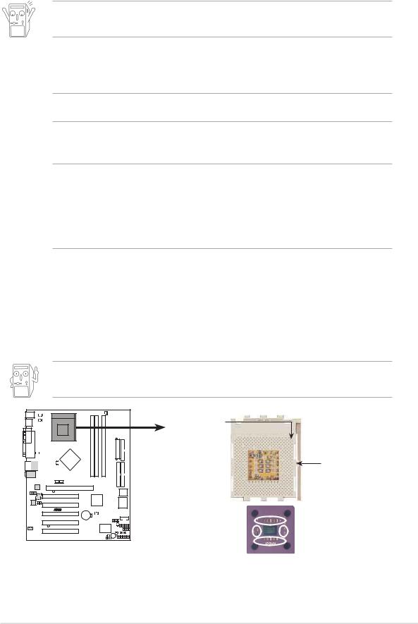
1.6Central Processing Unit (CPU)
The motherboard provides a Socket A (462) for CPU installation. AMD processors offer gigahertz speeds to support all the latest computing platforms and applications. The A7N8X supports Athlon™ XP processors with “QuantiSpeed” data processing, large data caches, 3D enhancements and 400/333/266Mhz bus speeds.
Do not use processors with core speeds of less than 1GHz on this motherboard.
CPU NOTCH
TO INNER
CORNER
A7N8X |
AMD™ CPU |
LOCK
 LEVER
LEVER
 CPU NOTCH
A7N8X Socket 462
Each AMD CPU has a “marked” corner. This corner is usually indicated with a notch, and/or a golden square or triangle. Refer to this indicator while orienting the CPU.
ASUS A7N8X Motherboard |
1-7 |
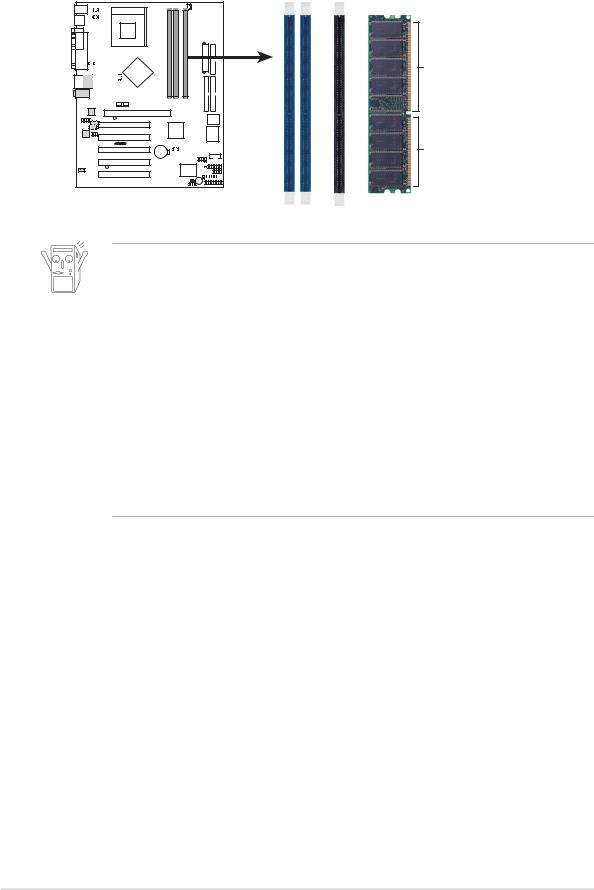
1.7System memory
The motherboard has three Double Data Rate (DDR) DIMM sockets that supports up to 3GB non-ECC PC3200/2700/2100/1600 DDR..
104 Pins
A7N8X |
80 Pins |
A7N8X 184-Pin DDR
DIMM Sockets
1.To enhance system performance, utilize dual-channel feature when installing additional DIMMs. Install the DIMMs in any of the following sequence: Sockets 1 & 3 or Sockets 2 & 3 or Sockets 1, 2 & 3.
2.DIMMs with more than 8 devices on each side of the module are not supported.
3.Make sure the memory frequency and bus frequency setting in the BIOS are the same or set to [Auto] ensure system stability.
4.A DDR DIMM is keyed with a notch so that it fits in only one direction. DO NOT force a DIMM into a socket to avoid damaging the DIMM.
5.Visit ASUS website (www.asus.com) for latest DDR400 Qualified Vendor List.
1.7.1Installing a DIMM
1.Unlock a DIMM socket by pressing the retaining clips outward.
2.Align a DIMM on the socket. Make sure the notches on the DIMM exactly match the notches in the socket.
3.Firmly insert the DIMM into the socket until the retaining clips lock into place.
1.8Expansion slots
The A7N8X motherboard has six (6) expansion slots. The following sub-sections describe the slots and the expansion cards that they support.
1.8.1Configuring an expansion card
Some expansion cards need an IRQ to operate. Generally, an IRQ must be exclusively assigned to one function at a time. In a standard design configuration, 16 IRQs are available but most are already in use.
1-8 |
Chapter 1: Motherboard Information |
 Loading...