

Page 1
Service Source
Mac Pro
Updated: 4 March 2008
© 2006 Apple Computer, Inc. All rights reserved.
Page 2

Mac Pro
Contents
Basics
Overview 6
Serial Number Location 7
Take Apart
General Information 9
Opening the Computer 10
Hard Drives 12
Optical Drive Carrier and Optical Drives 15
Memory (FB-DIMMs) and Memory Riser Cards 19
PCI Express/Graphics Card 23
Power Supply 29
Power Supply Fan 38
AirPort Extreme Card 47
Bluetooth Card 50
Battery 52
Processor Heatsink Cover 54
Front Fan Assembly 59
Mac Pro RAID Card & Battery 62
Processor Heatsinks 68
Memory Cage with Rear Fan 73
Processors 76
ii
Page 3

Speaker Assembly 83
USB Cable 87
Logic Board 90
Front Panel Board 100
Power Button 105
AirPort Antenna Board with Cables 110
Optical Drive Power Cable 114
Optical Drive Data (Ribbon) Cable 117
Ambient Board 120
Ambient Board Cable 122
Bluetooth Antenna Board and Cable 124
Hard Drive Cable Harness 127
Hard Drive Temperature Sensor Cable 130
Hard Drive Temperature Sensor 133
Power Cable Harness 136
Troubleshooting
General Information 140
Memory 140
PCI Express Cards 141
Internal Cabling Matrix 141
Thermal Calibration 143
Block Diagram 144
Resetting the Logic Board 145
Power-On Self Test: RAM and Processor Verication 146
Diagnostic LEDs 147
Power Supply Verication 152
Mac Pro Firmware Updates 152
Symptom Charts 154
How to Use the Symptom Charts 154
Startup Failures 154
Fans 157
Other Failures 158
iii
Page 4

Upgrades
AirPort Extreme Card 162
Bluetooth Card 165
PCI Express/Graphics Card 167
Views
Exploded View 172
External Views 174
Screw Matrix 176
iv
Page 5
Service Source
Basics
Mac Pro
© 2006 Apple Computer, Inc. All rights reserved.
Page 6
Overview
The Mac Pro form factor is similar to that of earlier Power Mac G5 models. However, the Mac Pro
includes several new hardware features, including:
Two dual-core Intel processors•
All Mac Pro models have two dual-core Intel Xeon processors, eectively making them quad
processor computers.
FB-DIMM memory supporting ECC and up to 16 GB of RAM•
Higher performance memory with support for error correction and greater capacity means
more room to grow when using high-performance computing applications.
Four internal hard drives•
Mac Pro supports up to four serial ATA (SATA) hard drives in easy-to-install drive carriers.
Two optical drives•
Mac Pro oers support for two cable-select optical drives
In addition to the features above, Mac Pro includes logic board diagnostic LEDs that help you
better diagnose hardware issues.
Mac Pro Basics 6
Page 7
Serial Number Location
To identify a particular Mac Pro computer, check the computer’s serial number. You can nd the
serial number within the model’s conguration label, which is located on the computer’s back
panel directly below the video ports.
Mac Pro Basics 7
Page 8

Service Source
Take Apart
Mac Pro
© 2006 Apple Computer, Inc. All rights reserved.
Page 9

General Information
Orientation
For most take-apart procedures, it is recommended that you lay the computer on its side before
removing or installing the part. For proper operation, however, Apple recommends that the
unit be run in the upright position. The computer should never be operated on its side with the
access panel facing down.
Tools
The following tools are required to service all congurations of the computer:
Long-handled magnetized Phillips #1 screwdriver•
Long-handled magnetized 3 mm athead hex screwdriver•
Short-handled, magnetized 2.5 mm hex wrench•
Flat-blade screwdriver•
Magnetized jewelers Phillips #1 screwdriver •
Magnetized jeweler’s Phillips #0 screwdriver•
Jeweler’s at-blade screwdriver•
Socket wrench•
Apple Mac Pro wrench (part number 922-8025)•
Needlenose pliers•
Scissors or wire cutters•
Xacto knife•
Nylon probe tool (black stick)•
Tape (for temporarily holding cables out of the way)•
Small mirror (for seeing small boards inside the enclosure)•
Soft cloth (for protecting the enclosure from scratches)•
Parts Requiring Enclosure Replacement
The following are not separate, orderable parts. To replace them, you must replace the enclosure.
Media shelf•
Rear panel latch•
Mac Pro Take Apart — General Information 9
Page 10

Opening the Computer
Tools
No tools are required for this procedure.
Preliminary Steps
Shut down the computer. 1.
Warning: Always shut down the computer before opening it to avoid damaging its internal
components or the components you are installing. Do not open the computer or attempt to
install items inside it while it is on.
Wait 5 to 10 minutes to allow the computer’s internal components to cool. 2.
Warning: After you shut down the system, the internal components can be very hot. You
must let the computer cool down before continuing.
Unplug all external cables from the computer except the power cord.3.
Touch the metal PCI access covers on the back of the computer to discharge any static 4.
electricity from your body.
Important: Always discharge static before you touch any parts or install any components
inside the computer. To avoid generating static electricity, do not walk around the room until
you have nished working and closed the computer.
Unplug the power cord. 5.
Warning: To avoid damaging its internal components or the components you want to
install, always unplug the computer before attempting any take-apart procedure.
Put on an ESD wrist strap.6.
Mac Pro — Opening the Computer 10
Page 11
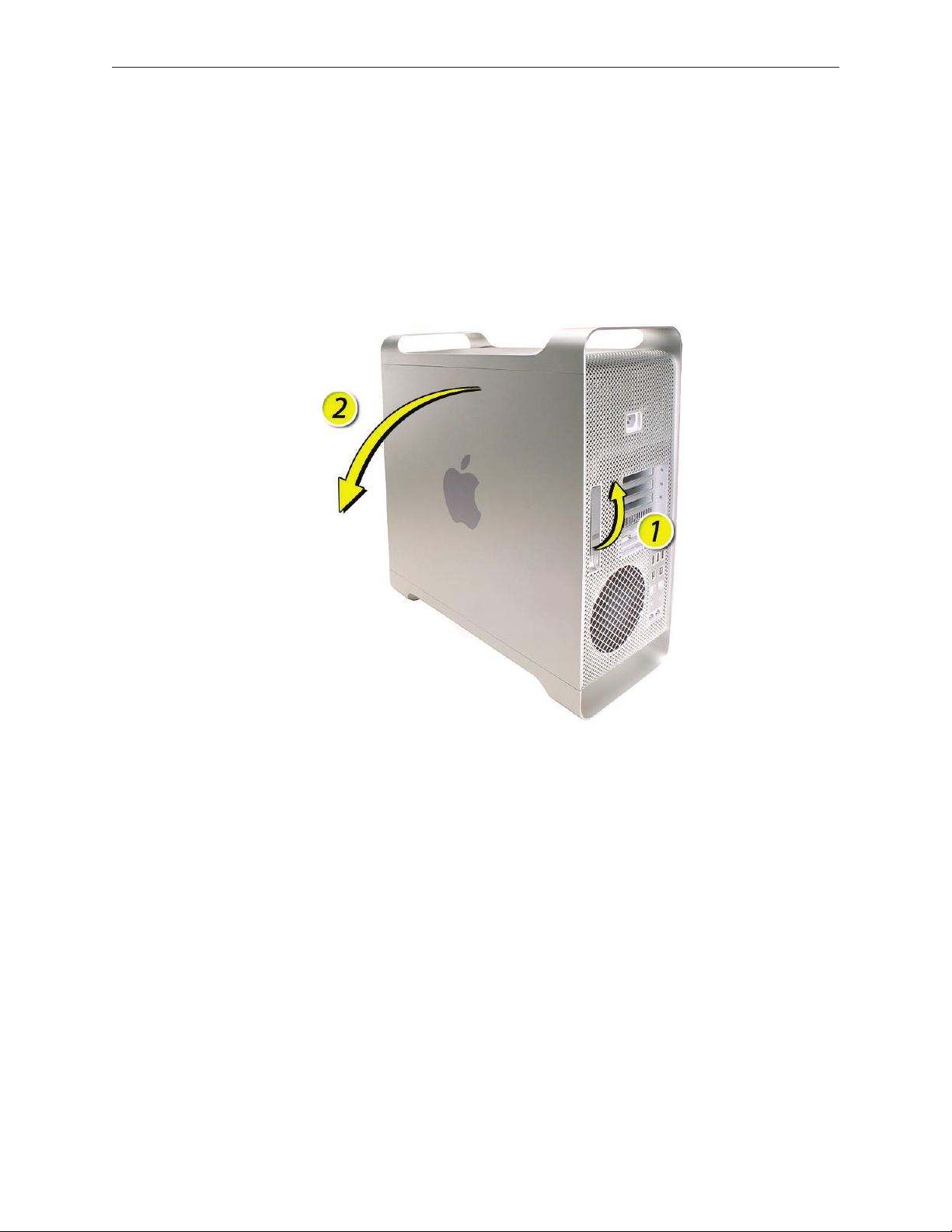
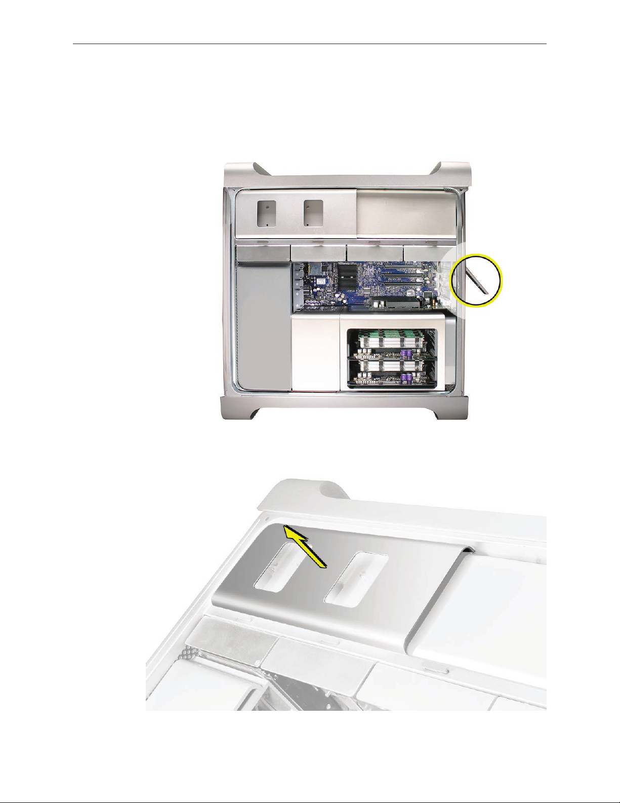
Procedure
Hold the side access panel and lift the latch on the back of the computer. 1.
Warning: The edges of the access panel and the enclosure can be sharp. Be very careful
when handling them.
Remove the access panel and place it on a at surface covered by a soft, clean cloth. 2.
Replacement Note: Make sure the latch is in the up position before replacing the access
panel. If the latch is down, the access panel will not seat correctly in the enclosure.
Mac Pro — Opening the Computer 11
Page 12

Hard Drives
The Mac Pro computer can accommodate four serial ATA (SATA) 3 Gbps hard drives in its four
internal hard drive bays. In most congurations, a single hard drive occupies the far left bay
(bay 1).
The hard drives must meet the following specications:
Type: SATA 3 Gbps•
Width: 3.9 inches (102 mm)•
Depth: 5.7 inches (147 mm)•
Height: 1.0 inch •
Tools
The only tool required for this procedure is a Phillips #1 screwdriver.
Preliminary Steps
Before you begin, open the computer, and lay it on its side with the access side facing up.
Important: Make sure the latch on the back panel is in the up position. When the latch is down,
the hard drives and carriers are locked in place and you will not be able to remove them.
Mac Pro Take Apart — Hard Drives 12
Page 13
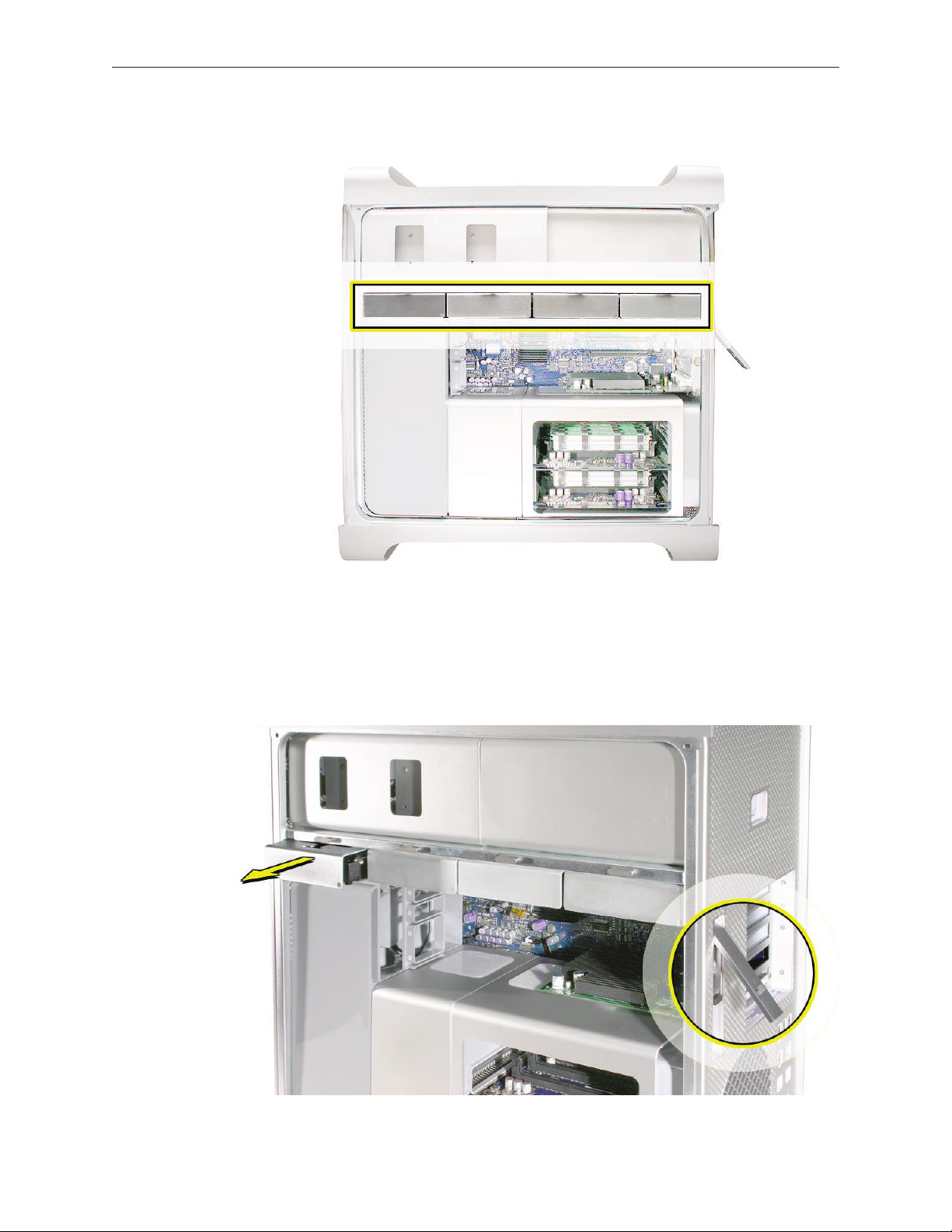
Part Location
Procedure
Make sure the latch on the back panel is up, so that the drives and carriers are unlocked.1.
Pull the hard drive out of the drive bay. 2.
Mac Pro Take Apart — Hard Drives 13
Page 14
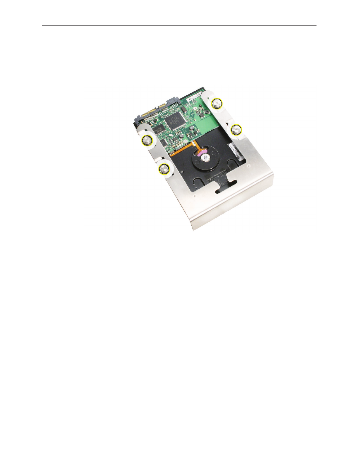
If you are replacing the hard drive with a new drive, remove the four screws that mount the 3.
drive to the carrier and mount the new drive in the carrier.
Important: Hold the drive by its sides. Be careful not to touch the printed circuit board on
the bottom of the drive.
Replacement Note: Slide the carrier and drive over the guides and into the drive bay, until you
feel the drive snap into place.
Note: If you install a new (replacement) drive, format it by following these steps:
Open Disk Utility and select the drive in the list to the left. 1.
Note: If you are formatting the primary drive, use the Disk Utility program on the Install Disk.
Click on the Partition tab.2.
Click on “Options” and verify GUID is selected if this is a bootable drive.3.
Apply the change by clicking on the “Partition” button.4.
Mac Pro Take Apart — Hard Drives 14
Page 15
Optical Drive Carrier and Optical Drives
The Mac Pro computer can accommodate two optical drives in the optical drive bay. If the
computer has only one optical drive, it is installed in the top position.
Note: To eject the drives, use the following:
Top drive: Press the Eject key.•
Bottom drive: Press the Option and Eject keys.•
Tools
The only tool required for this procedure is a Phillips #1 screwdriver.
Preliminary Steps
Before you begin, open the computer, and lay it on its side with the access side facing up.
Important: Make sure the latch on the back panel is in the up position. When the latch is down,
the optical drives and carrier are locked in place and you will not be able to remove them.
Part Location
Mac Pro Take Apart — Optical Drive Carrier and Optical Drives 15
Page 16
Procedure
Removing the Optical Drive Carrier and Optical Drives
Make sure the latch on the back panel is up, so that the drives and carriers are unlocked. 1.
Pull the optical drive carrier part way out of the computer. 2.
Mac Pro Take Apart — Optical Drive Carrier and Optical Drives 16
Page 17
Disconnect the power and ribbon cables from the optical drive(s) and remove the carrier. 3.
If you are replacing the optical drive with a new optical drive, do the following:4.
Remove the four mounting screws and remove the optical drive from the carrier.•
Use the four screws to mount the replacement drive in the carrier.•
Note: If you are adding a second drive to the carrier, use the four screws stored on the back of
the drive carrier to secure the drive to the carrier.
Mac Pro Take Apart — Optical Drive Carrier and Optical Drives 17
Page 18
Replacing the Optical Drive Carrier and Optical Drives
Important: Use the original Apple cables that came with the computer when you install or
replace the optical drives. If just one optical drive is installed, tuck the cables for the second drive
out of the way.
Attach the power and ribbon cables to the back of the drive(s). 1.
Important: Attach the connector on the end of the optical drive ribbon cable and the
connector in the middle of the optical drive power cable to the top drive. If there is a second
drive in the carrier, attach the remaining optical drive ribbon and power connectors to the
bottom drive.
Slide the optical drive carrier over the guides and into place in the optical drive bay.2.
Mac Pro Take Apart — Optical Drive Carrier and Optical Drives 18
Page 19
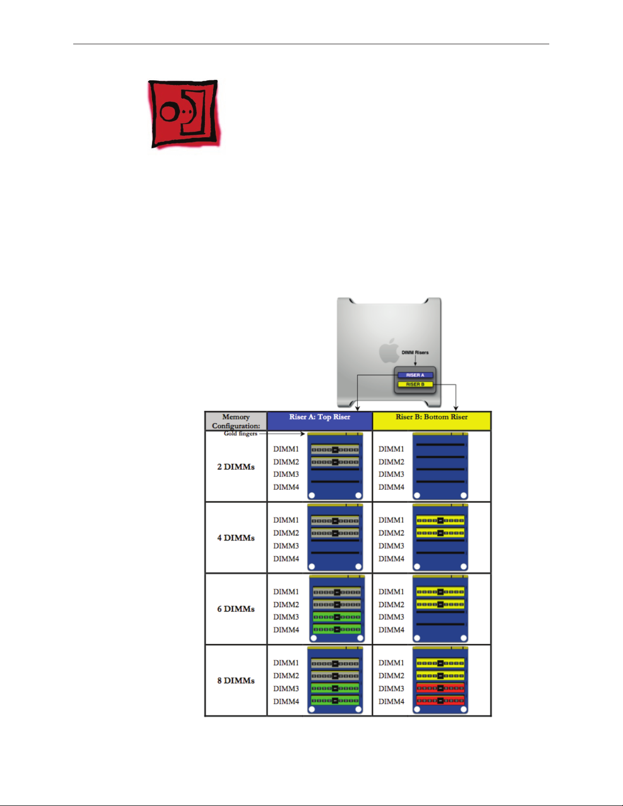
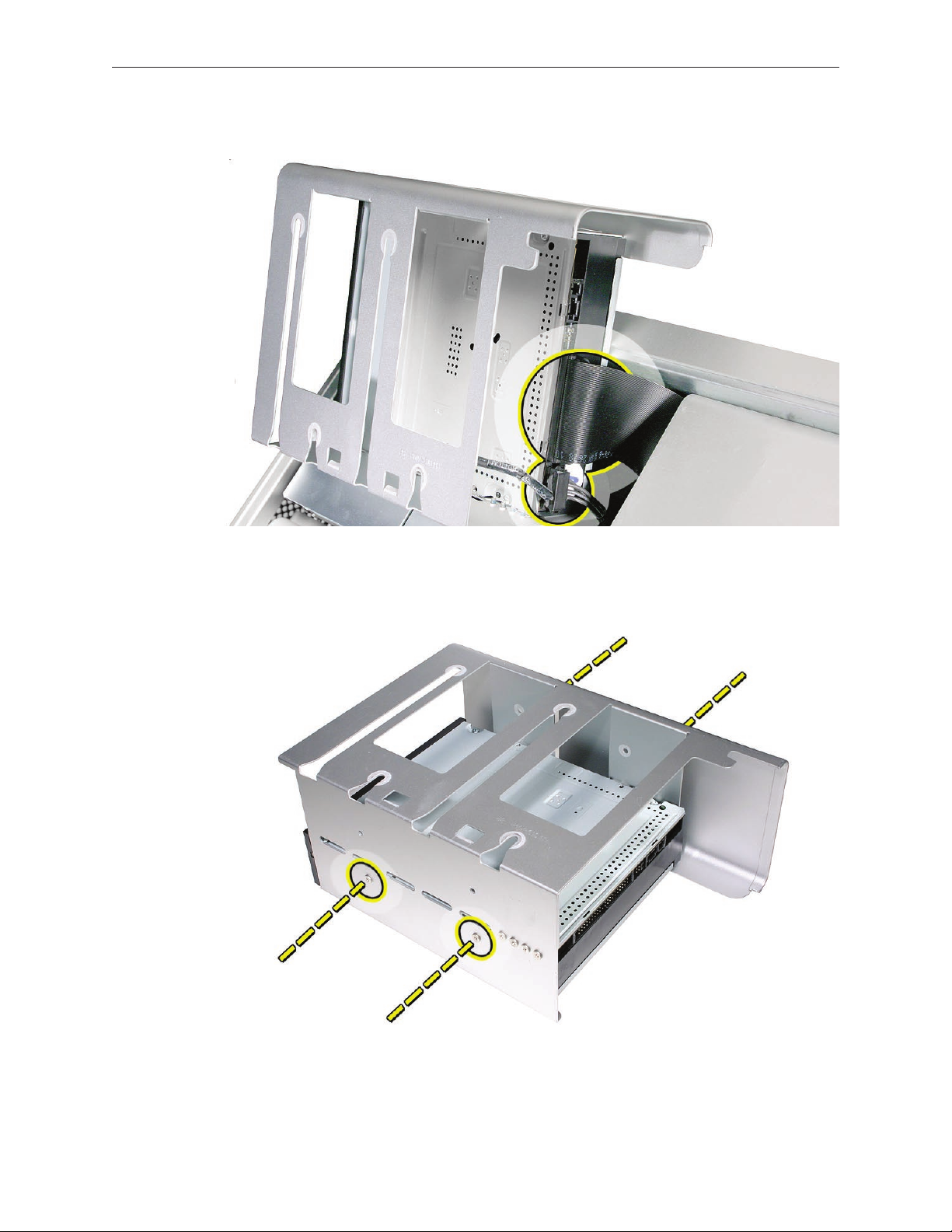
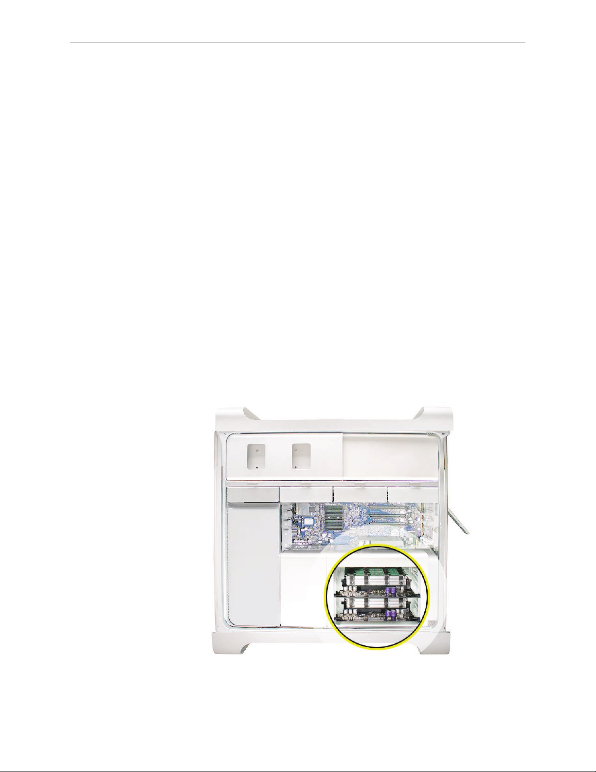
Memory (FB-DIMMs) and Memory Riser Cards
The Mac Pro computer has two memory riser cards with a total of 8 memory slots. On each card,
the slots are arranged as two banks of two slots each. The computer comes with a minimum of
1 GB of memory, installed as a pair of 512 MB fully buered, dual inline memory modules (FB-
DIMMs) in two of the DIMM slots. Additional DIMMs can be installed in the open DIMM slots, as
illustrated below.
Note: DIMMs must be installed in pairs of equal size from the same vendor. In the illustration
below, DIMMs in one colored pair do not need to match DIMMs in a dierent colored pair.
Mac Pro Take Apart — Memory (DIMMs) and Memory Riser Cards 19
Page 20
DIMMs for Mac Pro must t these specications:
667 MHz, FB-DIMMs•
72-bit wide, 240-pin modules•
36 devices maximum per DIMM•
Error-correcting code (ECC)•
Memory from older Macintosh computers is not compatible with Mac Pro.
Important: For proper operation of Mac Pro computers, Apple recommends using only Appleapproved Mac Pro FB-DIMMs. Refer to GSX for Apple FB-DIMMs service part numbers.
Tools
No tools are required for this procedure.
Preliminary Steps
Before you begin, open the computer, and lay it on its side with the access side facing up.
Warning: Always wait 5–10 minutes for the computer to cool down before you remove or install
memory. The DIMMs may be very hot.
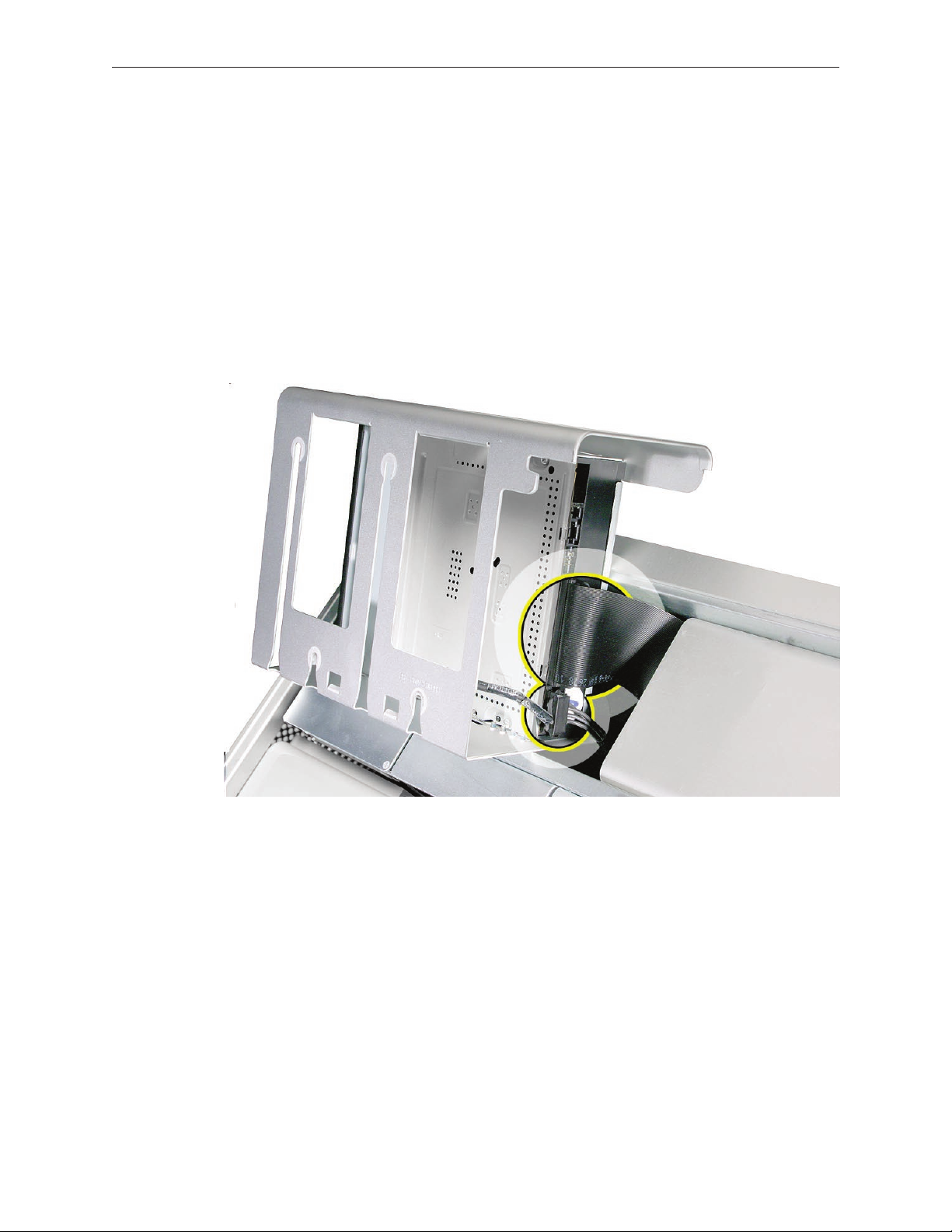
Part Location
Mac Pro Take Apart — Memory (DIMMs) and Memory Riser Cards 20
Page 21
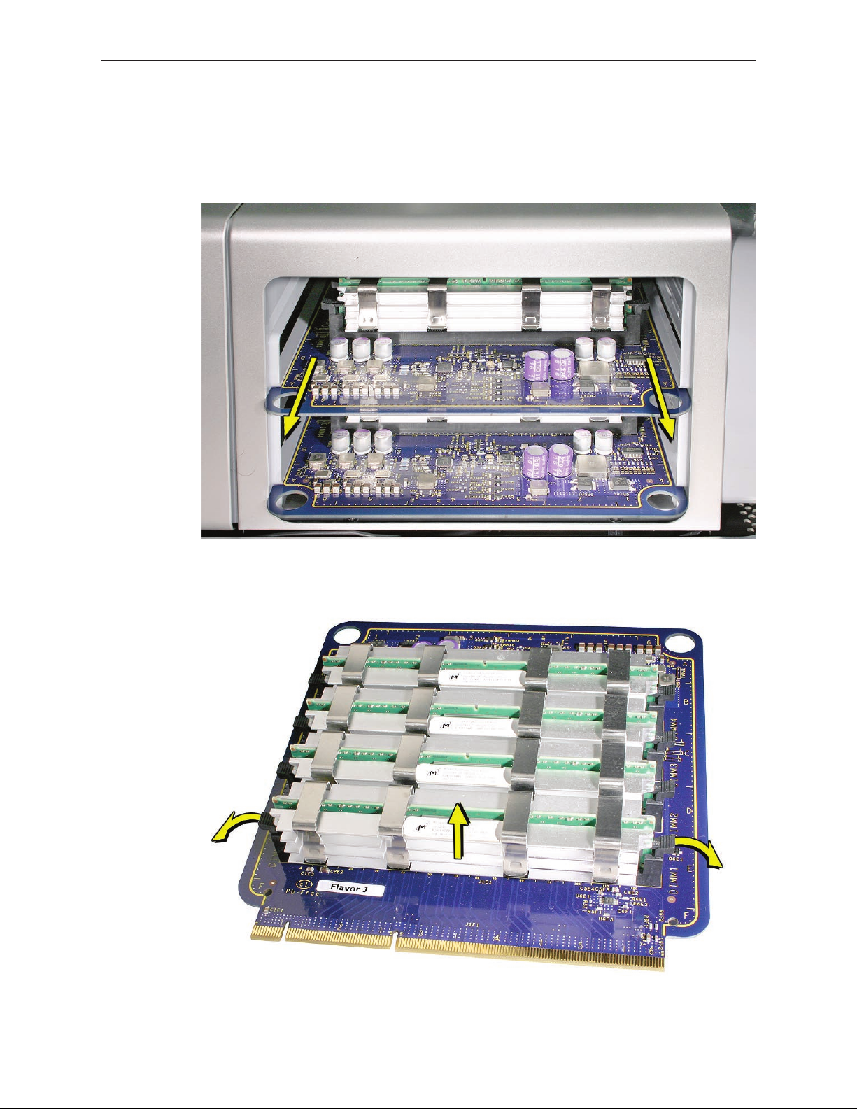
Procedure
Holding the memory riser card by the two nger holes, pull it out of the memory cage and 1.
place the card DIMM side up on a soft, clean cloth.
Open the ejectors on the DIMM slot by pushing them out to the sides, and remove the 2.
DIMM from the riser card.
Mac Pro Take Apart — Memory (DIMMs) and Memory Riser Cards 21
Page 22
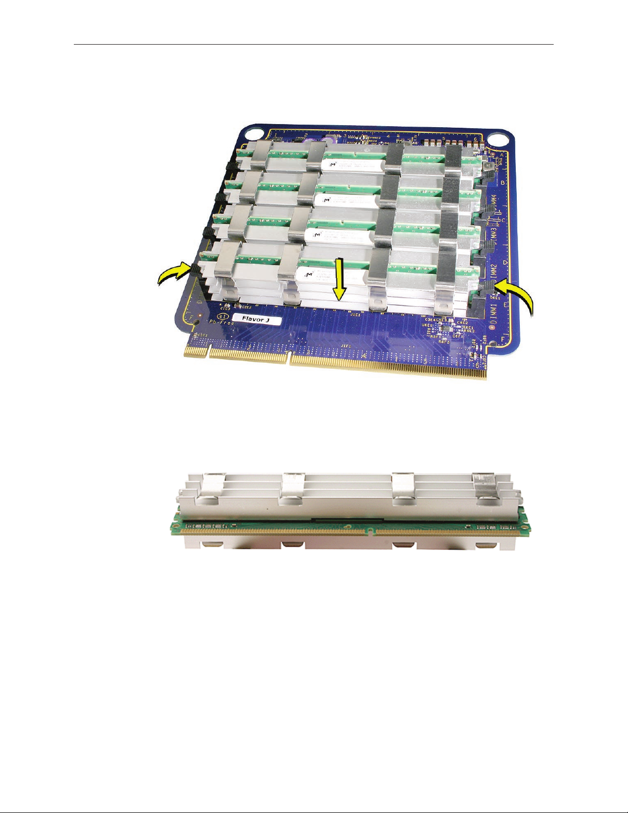
Replacement Note: Align the DIMM in the slot on the riser card and push both ends of the
DIMM down until the ejectors snap back up into place.
Warning: FB-DIMMs carry heatsinks on either side of the DIMM. Never attempt to remove the
heatsinks from the DIMMs. Doing so could damage the DIMM.
Mac Pro Take Apart — Memory (DIMMs) and Memory Riser Cards 22
Page 23
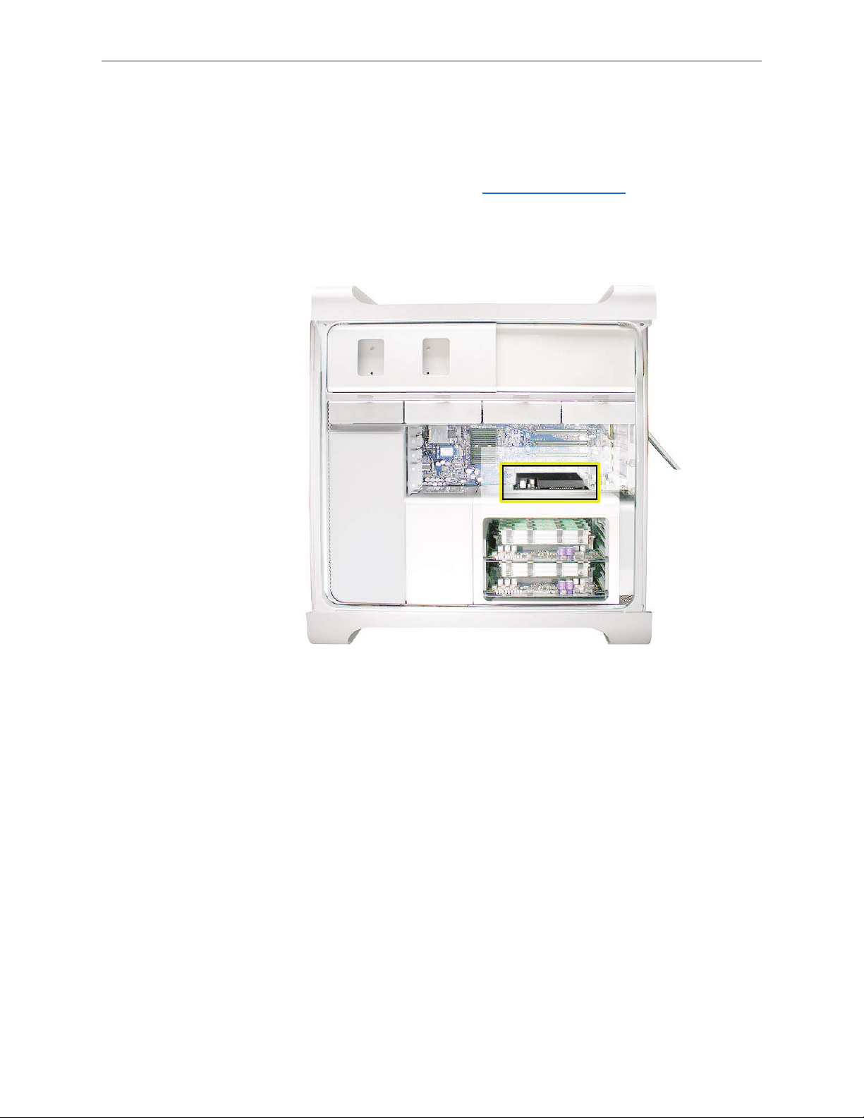
PCI Express/Graphics Card
Slot 1: Double-wide
PCI Express graphics
(graphics card installed)
Slots 2–4: PCI Express
The Mac Pro logic board includes one double-wide PCI Express graphics slot and three PCI
Express expansion slots, for a total of four slots. The computer comes with a graphics card
installed in slot 1. You can install additional PCI Express graphics and expansion cards in the
remaining three PCI Express expansion slots.
Important: Graphics cards from previous Power Mac G5 models are not compatible with Mac
Pro models. In addition, Mac Pro graphics cards are not compatible with Power Mac G5 models.
Important: Combined maximum power consumption for all four PCI Express slots must not
exceed 300 W.
Note: Port 2 of the ATI Radeon X1900 XT graphics card is compatible with the Apple DVI-to-video
adapter. See KnowledgeBase article 304910.
Tools
The only tool required for this procedure is a Phillips #1 screwdriver.
Mac Pro Take Apart — PCI Express/Graphics Card 23
Page 24
Preliminary Steps
Before you begin, open the computer, and lay it on its side with the access side facing up.
Note: You may also nd it helpful to remove the hard drives and carriers and any adjacent PCI
Express cards before beginning this procedure.
Part Location
Mac Pro Take Apart — PCI Express/Graphics Card 24
Page 25
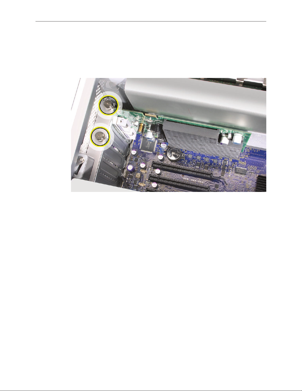
Procedure
This procedure explains how to remove a standard card and a card that includes a booster cable.
Before you can remove either type of card, however, you must rst loosen the two captive screws
that secure the PCI bracket to the enclosure and remove the bracket.
Warning: When removing or installing a card, handle it only by the edges. Do not touch its
connectors or any of the components on the card. Lift the card straight out from the connector
to remove it, and insert it straight into the connector to install it. Do not rock the card from side
to side and don’t force the card into the slot. Once the replacement card is installed, pull on it
gently to check that it is properly connected.
Mac Pro Take Apart — PCI Express/Graphics Card 25
Page 26
Standard Card
Release the small locking clip at the front of the card’s logic board connector by pushing the 1.
clip up toward the media shelf.
Holding the card by the top corners, pull up the card and remove it from its expansion slot.2.
Replacement Note: Align the card’s connector with the expansion slot and press until the
connector is inserted all the way into the slot. If you’re installing a 12-inch card, make sure the
card engages the appropriate slot in the PCI card guide.
Don’t rock the card from side to side; instead, press the card straight into the slot. •
Don’t force the card. If you meet a lot of resistance, pull the card out. Check the connector •
and the slot for damage or obstructions, then try inserting the card again.
Pull the card gently to see if it is properly connected. If it resists and stays in place and its •
gold connectors are barely visible, the card is connected.
Mac Pro Take Apart — PCI Express/Graphics Card 26
Page 27
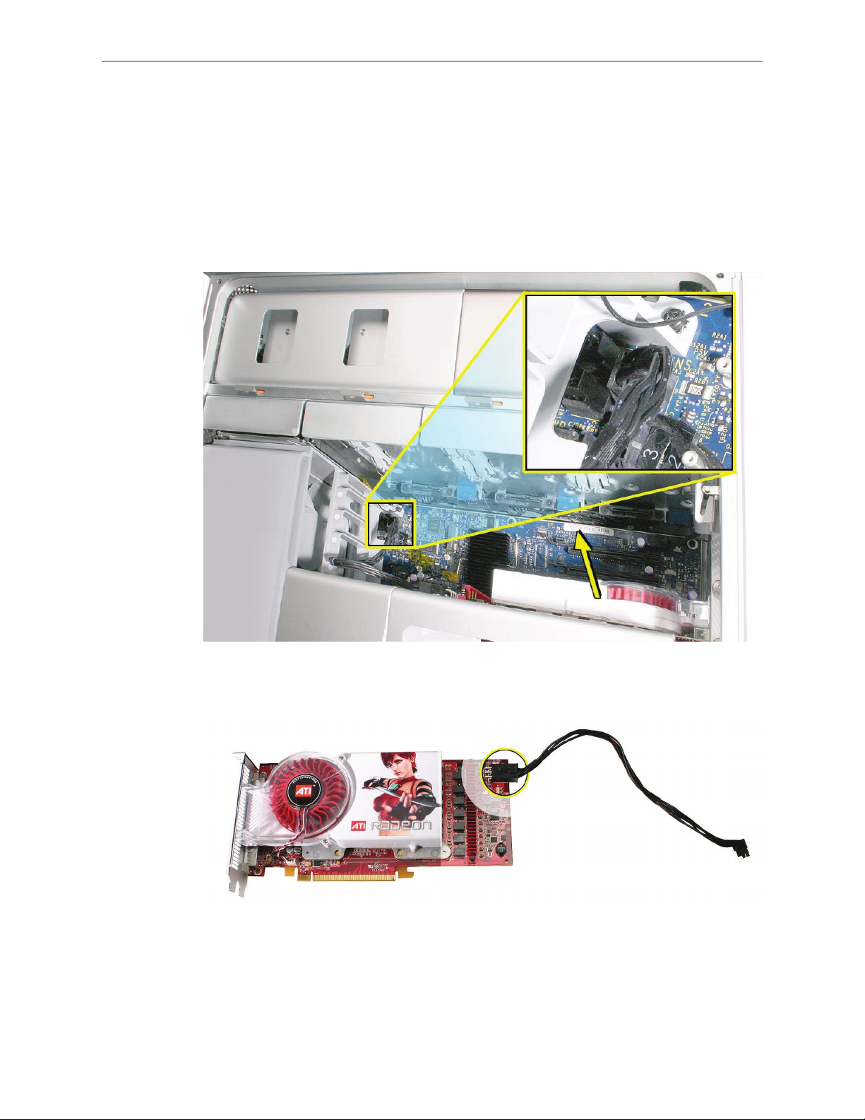
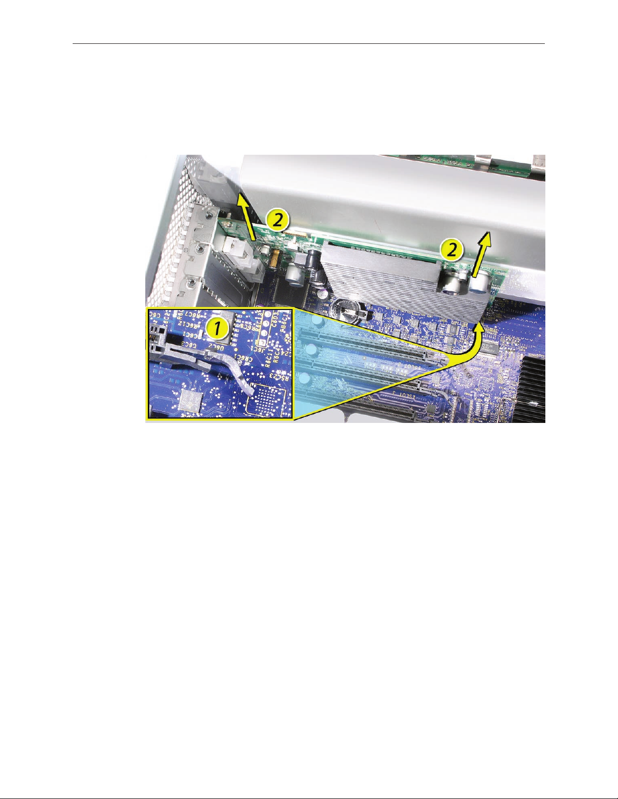
Card with Booster Cable
Disconnect the booster cable from the logic board.1.
Release the small locking clip at the front of the card’s logic board connector by pushing the 2.
clip up toward the media shelf.
Holding the card by the top corners, gently pull up the card and remove it from its 3.
expansion slot.
If you are replacing the booster cable with a new booster cable, disconnect the cable from 4.
the card.
Mac Pro Take Apart — PCI Express/Graphics Card 27
Page 28
Replacement Note: There are two logic board connectors for booster cables. Connect the
booster cable for a card in PCI slot 1 to the lower connector. Connect the booster cable for a card
in PCI slot 2 to the upper connector.
Mac Pro Take Apart — PCI Express/Graphics Card 28
Page 29
Power Supply
Tools
The only tool required for this procedure is a magnetized 2.5 mm hex wrench. You may also nd
a at-blade screwdriver helpful in releasing some cable connectors.
Preliminary Steps
Before you begin, open the computer, lay it on its side with the access side facing up, and remove
the following:
Hard drives and hard drive carriers in drive bays 3 and • 4
Optical drive carrier and optical drive• s
Any PCI Express cards that block access to the power supply mounting screw• s
Part Location
Mac Pro Take Apart — Power Supply 29
Page 30
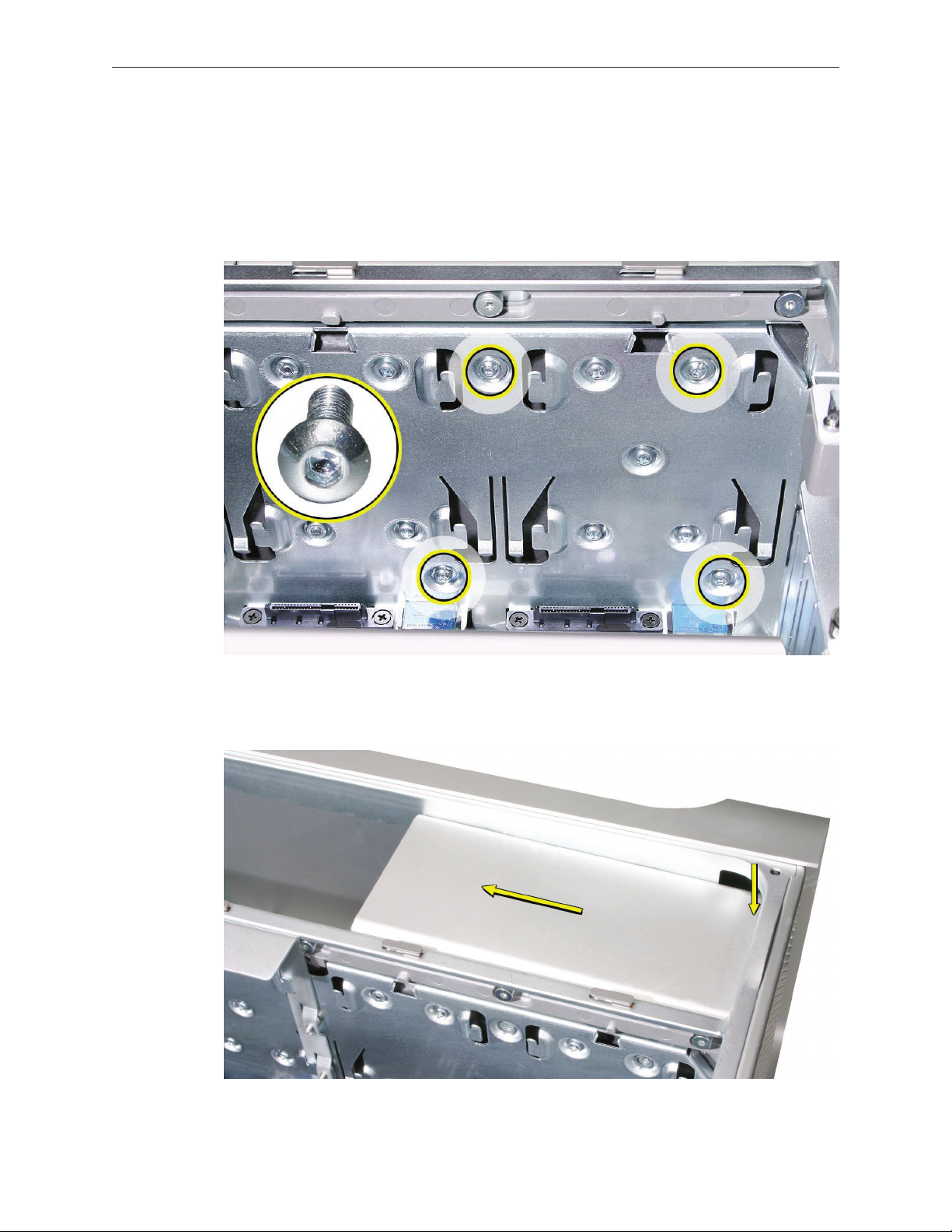
Procedure
Removing the Power Supply
Using a magnetized 2.5 mm hex wrench remove the four power supply mounting screws 1.
from the bottom of the media shelf.
Depress the upper right corner of the power supply and slide the power supply toward the 2.
front of the computer.
Mac Pro Take Apart — Power Supply 30
Page 31

Note: Before beginning the next step, place a soft cloth over the edge of the enclosure to
prevent scratches from the power supply.
Lift the power supply a short distance and rest it on the edge of the enclosure. 3.
Note: The power supply is still connected to the enclosure by its cable. To remove the power
supply entirely from the enclosure, you must disconnect the power supply cable’s four
connectors, which mate with four power harness connectors threaded through openings in
the media shelf’s vertical divider.
Mac Pro Take Apart — Power Supply 31
Page 32

Starting with the top connector and working down, disconnect the four connectors on the 4.
power supply cable from the four connectors on the power harness cable.
Note: You must release the locking latch on each power supply cable connector before
detaching the connector.
Remove the power supply from the enclosure.5.
Mac Pro Take Apart — Power Supply 32
Page 33

Replacing the Power Supply
Note: To protect against scratches, make sure a soft cloth covers the edge of the enclosure next
to the power supply bay.
Rest the power supply on the edge of the enclosure so that its cable can reach the media 1.
shelf divider.
Note: The following four steps explain how to reconnect the power supply cable connectors
with the power harness connectors. When the power harness connectors are in their original
position in the media shelf divider, it is not possible to see where they mate with the power
supply cable connectors. Therefore, the next step shows how to temporarily remove the
power harness connectors from the divider for a better line of sight.
Mac Pro Take Apart — Power Supply 33
Page 34

Starting with the top connector and working down, release the four power harness cable 2.
connectors from their openings in the media shelf divider.
Note: Each connector has two locking latches that hold it to the divider. To release the
connector, depress the bottom latch rst and then the top latch. You may nd a at-blade
screwdriver useful in depressing the latches.
Placing a hand on either side of the media shelf divider, thread the J1 connector on the 3.
power supply cable through the top connector opening in the media shelf divider and
connect it to the PS1 connector on the power harness.
Mac Pro Take Apart — Power Supply 34
Page 35

Repeat for the other three power supply cable connectors.
Important: 4. The rst three connectors on the power supply cable are marked J1, J2, and J3;
the fourth connector is not marked. The four connectors on the power harness cable are
marked PS1, PS2, PS3, and PS4. You must connect J1 to PS1, J2 to PS2, etc.
Starting at the bottom connector and working up, depress the locking latches on each 5.
power harness connector and reinsert it into its opening in the media shelf divider.
Mac Pro Take Apart — Power Supply 35
Page 36

Important: Test that all power supply cable connectors and power harness connectors are
fully seated by tugging on the cables on both sides of each of the four paired connectors.
Fold the power supply cable on the bottom of the power supply bay.6.
Lift the power supply and remove the soft cloth from the edge of the enclosure.7.
Holding the power supply at an angle, as illustrated, lower it into the enclosure until its 8.
upper right corner slides under the corner lip of the enclosure.
Mac Pro Take Apart — Power Supply 36
Page 37

Slide the power supply toward the back of the computer as far as possible. 9.
Make sure the power receptacle aligns with the opening in the enclosure’s back panel and 10.
the four screw holes in the power supply align with the screw holes in the media shelf.
Replace the four power supply mounting screws.11.
Mac Pro Take Apart — Power Supply 37
Page 38

Power Supply Fan
Tools
The only tools required for this procedure are a magnetized 2.5 mm hex wrench and needlenose
pliers. You may also nd scissors or wire cutters helpful.
Preliminary Steps
Before you begin, open the computer, lay it on its side with the access side facing up, and remove
the following:
Hard drives and hard drive carriers in drive bays 3 and • 4
Optical drive carrier and optical drive• s
Any PCI Express cards that block access to the power supply mounting screw• s
Part Location
Mac Pro Take Apart — Power Supply Fan 38
Page 39

Procedure
Note: To remove the power supply fan, you must rst move the power supply out of the way; you
do not, however, have to remove the power supply entirely from the enclosure.
Using a magnetized 2.5 mm hex wrench, remove the four power supply mounting screws 1.
from the bottom of the media shelf.
Depress the upper right corner of the power supply and slide the power supply toward the 2.
front of the computer.
Mac Pro Take Apart — Power Supply Fan 39
Page 40

Note: Before beginning the next step, place a soft cloth over the edge of the enclosure to
prevent scratches from the power supply.
Lift the power supply a short distance and rest it on the edge of the enclosure. 3.
Note: The power supply is still connected to the enclosure by its cable. When moving the
power supply to the edge of the enclosure, be careful not to put too much tension on the
cable.
Mac Pro Take Apart — Power Supply Fan 40
Page 41

Disconnect the power supply fan cable from the logic board and thread the cable through 4.
the opening in the media shelf.
Using needlenose pliers, pull out the four grommets that mount the power supply fan to the 5.
media shelf divider.
Note: You may nd scissors or wire cutters useful in snipping o the grommet heads.
Mac Pro Take Apart — Power Supply Fan 41
Page 42

Rotate the fan and remove it from the enclosure.6.
Mac Pro Take Apart — Power Supply Fan 42
Page 43

Replacing the Power Supply Fan
Place the power supply fan in the media shelf and thread the fan’s cable through the 1.
opening in the shelf.
Connect the cable to the logic board.2.
Rotate the fan into place ush against the media shelf divider. Make sure the back of the fan 3.
faces the divider, as illustrated.
Mac Pro Take Apart — Power Supply Fan 43
Page 44

Note: To secure the power supply fan to the divider, use the long-tailed grommets enclosed
with the replacement fan.
Thread the rst grommet, tail rst, through one of the four grommet holes in the divider 4.
and on through the corresponding grommet hole in the fan bracket. Then pull to secure the
grommet and detach the excess threading tail. (The tail is notched to break o at the correct
place.)
Repeat for the other three grommets. 5.
Mac Pro Take Apart — Power Supply Fan 44
Page 45

Fold the power supply cable on the bottom of the power supply bay.6.
Holding the power supply at an angle, as illustrated, lower it into the enclosure until its 7.
upper right corner slides under the corner lip of the enclosure.
Slide the power supply toward the back of the computer as far as possible. 8.
Mac Pro Take Apart — Power Supply Fan 45
Page 46

Make sure the power receptacle aligns with the opening in the enclosure’s back panel and 9.
the four screw holes in the power supply align with the screw holes in the media shelf.
Replace the four power supply mounting screws.10.
Mac Pro Take Apart — Power Supply Fan 46
Page 47

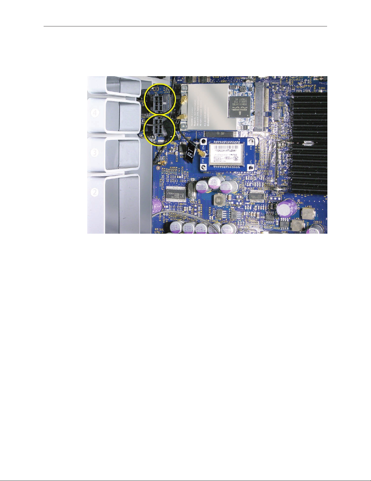
AirPort Extreme Card
Important: The computer enclosure includes AirPort antenna wires and a Bluetooth antenna
wire. The Bluetooth antenna wire looks similar to the AirPort antenna wires, except that it
includes a “BT” label. For proper operation, be careful not to connect the Bluetooth antenna wire
to the AirPort card or any AirPort antenna wire to the Bluetooth card.
Note: You may connect the AirPort antenna wires to either AirPort card connector.
Tools
The only tool required for this procedure is a magnetized jewelers Phillips #1 screwdriver.
Preliminary Steps
Before you begin, open the computer, and lay it on its side with the access side facing up.
Part Location
Mac Pro Take Apart — AirPort Extreme Card 47
Page 48

Procedure
Remove the two AirPort Extreme card mounting screws.1.
Lift the AirPort Extreme card a short distance from the logic board.2.
Disconnect the AirPort antenna wires from the card. 3.
Mac Pro Take Apart — AirPort Extreme Card 48
Page 49

Remove the card from the enclosure.4.
Replacement Note: To replace the AirPort Extreme card, do the following:
Connect the antenna wires to the card. •
Important: Be sure to connect the wires that are marked 1 and 3 to the card; the antenna
wire that is marked 2 should be taped out of the way.
Insert the card into its logic board connector at an angle, as illustrated. •
Lower the screw end of the card down to the standos on the logic board and replace the •
two mounting screws.
Note: If you are not replacing the AirPort card, cover the connectors on the AirPort antenna wires
with Kapton or other non-conductive tape to prevent them from shorting out components on
the logic board.
Mac Pro Take Apart — AirPort Extreme Card 49
Page 50

Bluetooth Card
Important: The computer enclosure includes one Bluetooth antenna wire, which looks similar
to the AirPort antenna wires, except that it includes a “BT” label. For proper operation, be careful
not to connect the Bluetooth antenna wire to the AirPort card or any AirPort antenna wire to the
Bluetooth card.
Tools
The only tool required for this procedure is a magnetized jewelers Phillips #1 screwdriver.
Preliminary Steps
Before you begin, open the computer, and lay it on its side with the access side facing up.
Part Location
Mac Pro Take Apart — Bluetooth Card 50
Page 51

Procedure
Remove the two Bluetooth card mounting screws. 1.
Lift the Bluetooth card a short distance from the logic board.2.
Disconnect the Bluetooth antenna wire from the card.3.
Remove the card from the enclosure. 4.
Note: If you are not replacing the Bluetooth card, cover the connector on the Bluetooth antenna
wire with Kapton or other non-conductive tape to prevent it from shorting out components on
the logic board.
Mac Pro Take Apart — Bluetooth Card 51
Page 52

Battery
Tools
No tools are required for this procedure. You may, however, nd a at-blade screwdriver useful in
removing the battery from its holder.
Preliminary Steps
Before you begin, open the computer, lay it on its side with the access side facing up, and remove
any PCI Express cards that block access to the battery.
Part Location
Mac Pro Take Apart — Battery 52
Page 53

Procedure
Slide the battery out from underneath the battery holder’s metal clip.1.
Remove the battery from its holder. 2.
Replacement Note: Insert the new battery into the holder, making sure the battery’s positive
symbol (+) faces up.
Warning: Installing the battery incorrectly may cause an explosion. Be sure the battery’s positive
and negative sides are correctly oriented in the holder. Use only the same type of battery or an
equivalent recommended by the manufacturer of the original.
Important: Batteries contain chemicals, some of which may be harmful to the environment.
Please dispose of used batteries according to your local environmental laws and guidelines.
Mac Pro Take Apart — Battery 53
Page 54

Processor Heatsink Cover
Tools
The only tools required for this procedure are the following:
Long-handled, magnetized #1 Phillips screwdriver•
Short-handled, magnetized jeweler’s #1 Phillips screwdriver or right-angle, magnetized #1 •
Phillips screwdriver
Apple Mac Pro wrench (part number 922-8025)•
Flat-blade screwdriver•
Preliminary Steps
Before you begin, open the computer, lay it on its side with the access side facing up, and remove
the following:
PCI Express card installed in slot • 1
Top and bottom memory card• s
Part Location
Mac Pro Take Apart — Processor Heatsink Cover 54
Page 55

Procedure
Note: To remove the heatsink cover, you must rst slide the memory cage toward the back panel.
Using a long-handled, magnetized #1 Phillips screwdriver, remove the two long screws that 1.
mount the memory cage to the logic board.
Using a short-handled, magnetized jeweler’s #1 Phillips screwdriver or right-angle, 2.
magnetized #1 Phillips screwdriver, carefully remove the two short screws that mount the
memory cage to the bottom panel of the enclosure.
Important: As you start to unscrew each short screw, look directly below the cage for the
screw’s stando. If the stando starts to turn as you turn the screwdriver, use the Apple Mac
Pro wrench (part number 922-8025) to hold the stando in place while you turn the screw.
Mac Pro Take Apart — Processor Heatsink Cover 55
Page 56

If either of the two short mounting screws for the memory cage strip while you are
attempting to remove it, the screw will stay attached to its hex stando located below the
cage and you will be unable to remove the screw. In this case, do the following.
Note: To avoid scratching the enclosure in the following step, place a piece of sticky note
paper or removable masking tape over the enclosure edge where you insert the wrench.
• Insert the Apple Mac Pro wrench (part number 922-8025) around the hex stando located
directly below the stripped screw, as illustrated. Turn the wrench to separate the hex stando
from the enclosure. If both screws are stripped, alternate turning the wrench between the
two standos so that the memory cage rises evenly.
• Using a at-blade screwdriver, lift the cage over both standos and slide the cage as
described in step 3.
See also the replacement note for cages with stripped screws in “Memory Cage with
Rear Fan.” In addition, order screw 922-7703 to replace any stripped, short screws used in
securing the memory cage.
Mac Pro Take Apart — Processor Heatsink Cover 56
Page 57

Slide the memory cage toward the rear panel of the computer. 3.
Lift the heatsink cover slightly, rotate it as illustrated, and remove the cover from the
enclosure.
Mac Pro Take Apart — Processor Heatsink Cover 57
Page 58

Replacement Note: When reinstalling the processor heatsink cover, do the following:
Make sure the heatsink cover slides below slot #1 on the PCI card guide, which is attached to •
the front fan assembly.
Align the four slots on the underside of the heastink cover’s left edge with the four tabs on •
the front fan before snapping the heatsink cover into place. (The slots on the underside of
the cover’s right edge should automatically align with the tabs on the memory cage, once
you slide the cage back into its original position.)
Slide the memory cage back into place and secure it with the four mounting screws, making •
sure you do not over-torque the screws.
Mac Pro Take Apart — Processor Heatsink Cover 58
Page 59

Front Fan Assembly
Tools
The only tools required for this procedure are a long-handled, magnetized #1 Phillips screwdriver
and the cover from a PCI Express card slot.
Preliminary Steps
Before you begin, open the computer, lay it on its side with the access side facing up, and remove
the following:
Hard drives and hard drive carriers in drive bays 1 and • 2
PCI Express card installed in slot • 1
Any 12-inch PCI Express card• s
Top and bottom memory card• s
Processor heatsink cove• r
Part Location
Mac Pro Take Apart — Front Fan Assembly 59
Page 60

Procedure
Using a long-handled, magnetized #1 Phillips screwdriver, remove the front fan assembly 1.
mounting screw.
Insert the right-angle end of a cover for one of the PCI Express card slots between the 2.
enclosure and the lower left edge of the front fan, and using force, lift straight up. Then
gripping the front fan by the upper right edge and the lower left edge, lift straight up and
remove the fan from the enclosure.
Note: You may have to use some force when lifting the fan assembly from the enclosure.
Mac Pro Take Apart — Front Fan Assembly 60
Page 61

Replacement Note: When lowering the front fan into the enclosure, slide the guide on the base
of the fan assembly into the channel on the speaker assembly.
Also make sure the latch on the inside top left edge of the fan assembly engages with the slot
on the inside lip of the enclosure. Then press down until you hear the fan click into place in the
connector on the logic board
Replacement Note: Be careful not to crimp any AirPort or Bluetooth antenna wires under the fan
assembly. Also make sure that the fan cables are routed in the fan channel.
Mac Pro Take Apart — Front Fan Assembly 61
Page 62

Mac Pro RAID Card & Battery
Note: If a Mac Pro RAID Card is installed in a Mac Pro, the standard iPass cable routing has been
changed so that the cable connects to the card, rather than to the logic board.
Tools
The only tool required for this procedure is a Phillips #1 screwdriver. You might also nd a small
at-blade screwdriver helpful in releasaing the iPass cable connector.
Preliminary Steps
Before you begin, open the computer, lay it on its side with the access side facing up, and remove
the following:
All h• ard drives and hard drive carriers
PCI Express card installed in slot 1 and a• ny 12-inch PCI Express cards
Top and bottom memory cards•
Processor heatsink cove• r
Front fan assembl• y
Part Location
Mac Pro Take Apart — Mac Pro RAID Card and Battery 62
Page 63

Procedure
If you have not already done so, loosen the two captive screws that secure the PCI bracket to 1.
the enclosure and remove the bracket.
Warning: When removing or installing a card, handle it only by the edges. Do not touch its
connectors or any of the components on the card. Lift the card straight out from the
connector to remove it, and insert it straight into the connector to install it. Do not rock the
card from side to side and don’t force the card into the slot. Once the replacement card is
installed, pull on it gently to check that it is properly connected.
Mac Pro Take Apart — Mac Pro RAID Card and Battery 63
Page 64

Release the small locking clip at the front of the card’s logic board connector by pushing the 2.
clip up toward the media shelf.
Holding the card by the top corners, gently pull up the card and remove it from its 3.
expansion slot.
Note: The Mac Pro RAID Card must always be installed in slot 4.
Mac Pro Take Apart — Mac Pro RAID Card and Battery 64
Page 65

Disconnect iPass cable from the Mac Pro RAID Card. 4.
Note: You may nd it helpful to use a small, at-blade screwdriver to release the cable
connector. Depress the rear edge of the silver-colored latch on top of the connector.
Remove the card from the enclosure.5.
Mac Pro Take Apart — Mac Pro RAID Card and Battery 65
Page 66

The Mac Pro RAID Card includes its own battery. 6.
If you are replacing the battery on the card, do the following:
• Disconnect the battery cable from the card.
• Remove the four mounting screws and lift the battery from the card.
Important: Do not drop, disassemble, crush, incinerate, or expose the battery to temperatures
above 212° F (100° C). Stop using the battery if it appears damaged in any way. Replace the
battery only with an Apple-authorized battery for this product. Dispose of used batteries
promptly according to your local environmental guidelines.
Mac Pro Take Apart — Mac Pro RAID Card and Battery 66
Page 67

Replacing the Mac Pro RAID Card
Connect the iPass cable to the Mac Pro RAID Card.1.
Align the card’s connector with expansion slot 4 and press until the connector is inserted all 2.
the way into the slot. Make sure the card also engages slot 4 in the PCI card guide.
Note:
Don’t rock the card from side to side; instead, press the card straight into the slot. •
Don’t force the card. If you meet a lot of resistance, pull the card out. Check the connector •
and the slot for damage or obstructions, then try inserting the card again.
Pull the card gently to see if it is properly connected. If it resists and stays in place and its •
gold connectors are barely visible, the card is connected.
Note: System Proler does not display the serial number for the Mac Pro RAID Card. You can nd
the serial number by checking the serial number sticker on the back of the card.
Mac Pro Take Apart — Mac Pro RAID Card and Battery 67
Page 68

Processor Heatsinks
Note: The processor heatsink requires thermal grease for proper operation. Every time you
remove the processor heatsink, you must replace the thermal grease. New grease and alcohol
wipes for cleaning o the previous grease are included with replacement processors and
logic boards. Instructions for applying the grease are included with this procedure. Note that
replacement processor heatsinks come with the grease already applied.
Tools
The only tool required for this procedure is a long-handled, magnetized 3 mm athead hex
screwdriver.
Preliminary Steps
Before you begin, open the computer, lay it on its side with the access side facing up, and remove
the following:
Hard drives and hard drive carriers in drive bays 1 and • 2
PCI Express card installed in slot • 1
Any 12-inch PCI Express card• s
Top and bottom memory card• s
Processor heatsink cove• r
Front fan assembl• y
Mac Pro Take Apart — Processor Heatsinks 68
Page 69

Part Location
Procedure
Disconnect the 2-pin cable for the upper processor (CPU A) heatsink from the logic board. 1.
Mac Pro Take Apart — Processor Heatsinks 69
Page 70

Using a long-handled, magnetized 3 mm athead hex screwdriver, loosen the four captive 2.
mounting screws for the upper processor heatsink in the order indicated below.
Lift the heatsink straight up and out of the enclosure.3.
Move the memory cage out of the way so that you can locate the cable connector for the 4.
lower processor heatsink.
Disconnect the cable. 5.
Repeat steps 2 and 3 for the lower processor (CPU B) heatsink.6.
Mac Pro Take Apart — Processor Heatsinks 70
Page 71

Replacement Note: Before reinstalling an existing processor heatsink, follow these directions for
applying new thermal grease to the underside of the heatsink.
Using the alcohol pad included with the logic board or processor replacement part, clean o •
any used thermal grease from the processor and the bottom of the heatsink.
Using the thermal grease included with the logic board or processor replacement part, apply •
one dot of fresh grease to the raised square area on the bottom of the heatsink.
Spread the grease evenly across the square to a thickness of approximately 1 mm. •
Warning: Do not apply more grease than recommended. The grease must not overow the
heatsink and come in contact with the processor connector.
Carefully align the posts on the heatsink with the mounting holes in the logic board, and •
lower the heatsink straight down onto the processor.
To ensure the grease spreads evenly over the processor, lightly tighten the heatsink •
mounting screws in the order indicated below.
To ax the heatsink to the processor, again tighten the screws in the order indicated.•
Mac Pro Take Apart — Processor Heatsinks 71
Page 72

Note: If you are replacing a processor heatsink with a new heatsink, do not reapply thermal
grease. The new heatsink comes with thermal grease already in place, covered by a cap over the
bottom of the heatsink. Before installing the heatsink, remove the cap.
Replacement Note: If you are replacing either the upper or lower processor heatsink with a new
heatsink, apply the enclosed gasket to the top of the heatsink, as illustrated below.
Replacement Note: If you are replacing the lower processor (CPU B) heatsink with a new
heatsink, install the enclosed bumpers on either side of the heatsink, as illustrated below. Do not
add bumpers to the heatsink for the upper processor (CPU A).
Mac Pro Take Apart — Processor Heatsinks 72
Page 73

Memory Cage with Rear Fan
The rear fan is part of the memory cage assembly. If you need to replace the rear fan, you must
replace the entire memory cage assembly.
Note: Every time you remove the memory cage, you must replace the thermal grease on
the processor heatsinks. New grease and alcohol wipes for removing the previous grease are
available as a separate kit (part number 076-1225). Instructions for applying the grease are
included with the processor heatsinks procedure.
Tools
The only tools required for this procedure are pliers, wirecutters, and a socket wrench.
Preliminary Steps
Before you begin, open the computer, lay it on its side with the access side facing up, and remove
the following:
Hard drives and hard drive carriers in drive bays 1 and • 2
PCI Express card installed in slot • 1
Any 12-inch PCI Express card• s
Top and bottom memory card• s
Processor heatsink cove• r
Front fan assembl• y
Processor heatsink• s
Mac Pro Take Apart — Memory Cage with Rear Fan 73
Page 74

Part Location
Procedure
Disconnect the rear fan cable from the logic board.1.
Lift the memory cage out of the enclosure.2.
Replacement Note: When installing the memory cage, make sure all cables are out of the way so
that the cage sits properly and the cable harness below it is not pinched or damaged when you
tighten the screws.
Mac Pro Take Apart — Memory Cage with Rear Fan 74
Page 75

Replacement Note for Cages with Stripped Screws: If either of the two short mounting
screws for the memory cage stripped while you were attempting to take out the heatsink cover
(see step 2 in “Processor Heatsink Cover,” the screw and hex stando will stay attached to
the memory cage when you remove it. In this case, before replacing the memory cage in the
enclosure, do the following.
• Using pliers and a socket wrench, separate the hex stando from the mounting screw.
• Replace the hex stando in the enclosure.
Note: To avoid future problems, make sure both standos are securely fastened before you
reinstall the memory cage.
Note: Order screw 922-7703 to replace any stripped, short screws used in securing the memory
cage..
Mac Pro Take Apart — Memory Cage with Rear Fan 75
Page 76

Processors
This procedure illustrates how to remove the lower processor (CPU B). The instructions are the
same for removing the upper processor (CPU A). You may, however, want to use a at-blade
screwdriver to release the latch on the upper processor.
Note: Every time you remove a processor, you must replace the thermal grease on the processor
heatsink. New grease and alcohol wipes for removing the previous grease are included with
replacement processors. Instructions for applying the grease are included with the processor
heatsinks procedure.
Identifying Version 1 and Version 2 Processors
There are two versions of the processor, Version 1 and Version 2, which must be replaced like-forlike. In addition, both processors in a dual conguration must be the same version, either
Version 1 or Version 2. Dierent versions in the same computer could cause a system failure.
Note: You may still replace a single processor, but you must replace it like for like. There is no
performance advantage to either version of the processor.
To identify the correct processor for the computer you are repairing, please check its
conguration code (the last three alphanumeric characters in the serial number for the
computer). The following table lists the conguration codes that use Version 2 processors; all
other conguration codes use Version 1 processors. If you do not have the correct processor,
please order it from GSX.
Conguration Code Version 2 Processor
0KW, 0L0, 0L5, 0L7, 0LD, 0LE, 0LH, 0GP 2.0 GHz (661-4612)
0KT, 0GN, 0KY, 0KZ, 0L1, 0L2, 0L4, 0L6, 0L9, 0LA, 0LC, 0GP 2.66 GHz (661-4613)
0KV, 0KU, 0HA, 0KX, 0L3, 0L8, 0LB, 0LL, 0LM, 0LP, 0GP 3.0 GHz (661-4614)
Tools
No tools are required for this procedure. However, you may nd a at-blade screwdriver helpful in
releasing the processor holder latch.
Mac Pro Take Apart — Processors 76
Page 77

Preliminary Steps
Before you begin, open the computer, lay it on its side with the access side facing up, and remove
the following:
Hard drives and hard drive carriers in drive bays 1 and • 2
PCI Express card installed in slot • 1
Any 12-inch PCI Express card• s
Top and bottom memory card• s
Processor heatsink cove• r
Front fan assembl• y
Processor heatsink• s
Memory cag• e
Part Location
Mac Pro Take Apart — Processors 77
Page 78

Procedure
Release the latch on the metal processor holder. 1.
Note: You may want to use a at-blade screwdriver to release the latch on the upper
processor.
Rotate the top of the holder to the open position. 2.
Mac Pro Take Apart — Processors 78
Page 79

Lift the processor out of the holder.3.
Important: When removing or installing a processor, always hold the processor by the edges.
Be extremely careful not to touch the gold pins on the bottom of the processor, as this type of
connector is very sensitive to contamination. Also be careful not to touch the gold pins in the
processor socket on the logic board.
Mac Pro Take Apart — Processors 79
Page 80

Note: You can identify the processor by the speed etched on the processor can, as illustrated
below. You must clean o the thermal grease from installed processors to see the speed.
Replacement Note: Before installing a replacement processor, remove the protective cap
covering the new processor’s connector.
Mac Pro Take Apart — Processors 80
Page 81

Replacement Note: When installing the processor on the logic board, align the processor notch
with the tab on the processor holder, as illustrated. Then lower the processor straight down onto
the socket.
Replacement Note: Make sure the two logic board bumpers by the upper processor are in place
before you reinstall the heatsinks.
Note: Unlike in earlier Power Mac G5 computers, replacing a processor in Mac Pro does not
require running Apple Service Diagnostic for thermal calibration..
Mac Pro Take Apart — Processors 81
Page 82

Important: For the new processor to perform properly, the logic board must be upgraded to the
latest version of the BootROM. You can download the latest version from the Apple support web
site: http://www.apple.com/support/downloads/
Specically, see KnowledgeBase article 303880, “Firmware Updates for Intel-based Macs.”
Mac Pro Take Apart — Processors 82
Page 83

Speaker Assembly
Tools
The only tools required for this procedure are a magnetized #1 Phillips screwdriver and a
magnetized jeweler’s #0 Phillips screwdriver.
Preliminary Steps
Before you begin, open the computer, lay it on its side with the access side facing up, and remove
the following:
Hard drives and hard drive carriers in drive bays 1 and • 2
PCI Express card installed in slot • 1
Any 12-inch PCI Express card• s
Top and bottom memory card• s
Processor heatsink cove• r
Front fan assembl• y
Mac Pro Take Apart — Speaker Assembly 83
Page 84

Part Location
Mac Pro Take Apart — Speaker Assembly 84
Page 85

Procedure
Remove the three speaker assembly mounting screws.1.
Carefully pivot the speaker assembly a short distance away from the enclosure. 2.
Disconnect the speaker assembly cable from the logic board. 3.
Remove the speaker assembly from the computer. 4.
Mac Pro Take Apart — Speaker Assembly 85
Page 86

If you are replacing the speaker in the assembly bracket, do the following: 5.
• Slide the speaker cable through the opening in the speaker bracket.
• Using a magnetized jeweler’s #0 Phillips screwdriver, remove the four mounting screws.
Remove the speaker and cable from the bracket.6.
Mac Pro Take Apart — Speaker Assembly 86
Page 87

USB Cable
Tools
No tools are required for this procedure.
Preliminary Steps
Before you begin, open the computer, lay it on its side with the access side facing up, and remove
the following:
Hard drives and hard drive carriers in drive bays 1 and • 2
PCI Express card installed in slot • 1
Any 12-inch PCI Express card• s
Top and bottom memory card• s
Processor heatsink cove• r
Front fan assembl• y
Mac Pro Take Apart — USB Cable 87
Page 88

Part Location
Mac Pro Take Apart — USB Cable 88
Page 89

Procedure
Disconnect the USB cable from connector J201 on the front panel board.1.
Disconnect the USB cable from connector J2D1 on the logic board. 2.
Remove the cable from the enclosure.3.
Mac Pro Take Apart — USB Cable 89
Page 90

Logic Board
Note: Every time you remove the logic board, you must replace the thermal grease on the
processor heatsinks. New grease and alcohol wipes for removing the previous grease are
included with replacement logic boards. Instructions for applying the grease are included with
the processor heatsinks procedure.
Tools
The only tool required for this procedure is a magnetized Phillips #1 screwdriver.
Preliminary Steps
Before you begin, open the computer, lay it on its side with the access side facing up, and remove
the following:
All hard drives and hard drive carrier• s
All PCI Express card• s
Top and bottom memory card• s
Processor heatsink cove• r
Front fan assembl• y
Processor heatsink• s
Memory cag• e
Speaker assembl• y
USB cabl• e
AirPort Ex• treme card (if installed)
Bluetooth card (if installed• )
Mac Pro Take Apart — Logic Board 90
Page 91

Part Location
Mac Pro Take Apart — Logic Board 91
Page 92

Procedure
To keep them out of the way, temporarily tape the antenna cables to the bottom of the 1.
media shelf.
Important: Be sure to disconnect all cables from the logic board before you remove the
logic board mounting screws.
Mac Pro Take Apart — Logic Board 92
Page 93

Starting at the back panel side of the logic board and working clockwise around the board, 2.
disconnect all cables from the logic board.
Note: There are 14 cables you will be disconnecting from the logic board.
Mac Pro Take Apart — Logic Board 93
Page 94

Using a magnetized #1 Phillips screwdriver, remove the eight black logic board mounting 3.
screws.
Mac Pro Take Apart — Logic Board 94
Page 95

Slide the logic board back a short distance from the port openings in the back panel. Make 4.
sure the ports clear the openings.
Tilt the top edge of the logic board up and maneuver the board out of the enclosure.5.
Mac Pro Take Apart — Logic Board 95
Page 96

Replacement Note: Before replacing the logic board, check the underside of the board to be
sure that all bumpers are in place. Replace any missing bumpers.
Replacement Note: Also check that the two bumpers are in place by the upper processor on the
top side of the logic board. Replace any missing bumpers.
Mac Pro Take Apart — Logic Board 96
Page 97

Replacement Note: If you are replacing the logic board with a new logic board, do the following:
Remove the protective caps from the new logic board’s processor holders and transfer the •
caps to the original logic board’s processor holders. Note that logic boards returned to Apple
without the protective caps may be rejected.
Warning: Be careful not to touch the gold pins in the processor socket on the logic board.
Mac Pro Take Apart — Logic Board 97
Page 98

T• ransfer the following to the new board:
Processors•
DIMMs•
PCI Express/graphics cards•
AirPort Extreme card (if installed)•
Bluetooth card (if installed)•
You must also transfer the back ports EMI shield to the new board.•
Replacement Note: To replace the logic board, tilt the board as illustrated and lower it into the
enclosure.
Note: Unlike in earlier Power Mac G5 computers, replacing a logic board in Mac Pro does not
require running Apple Service Diagnostic for thermal calibration.
Mac Pro Take Apart — Logic Board 98
Page 99

Important: For proper performance, all logic boards in Intel-based desktop computers and
servers must be upgraded to the latest version of the BootROM. You can download the latest
version from the Apple support web site:
http://www.apple.com/support/downloads/
Mac Pro Take Apart — Logic Board 99
Page 100

Front Panel Board
Tools
The only tool required for this procedure is a long-handled, magnetized Phillips #1 screwdriver.
Preliminary Steps
Before you begin, open the computer, lay it on its side with the access side facing up, and remove
the following:
Hard drives and hard drive carriers in drive bays 1 and • 2
PCI Express card installed in slot • 1
Any 12-inch PCI Express card• s
Top and bottom memory card• s
Processor heatsink cove• r
Front fan assembl• y
Mac Pro Take Apart — Front Panel Board 100
 Loading...