


DB2E 1500
DSB2E 1500
GB |
Instructions for use |
|
Please read and save these |
|
instructions. |
D |
Gebrauchsanleitung |
|
Bitte lesen und aufbewahren. |
F |
Instruction d’utilisation |
|
Prière de lire et de conserver. |
I |
Istruzioni d’uso |
|
Si prega di leggere le istruzioni e |
|
di conservarle. |
E |
Instrucciones de uso |
|
Lea y conserve estas |
|
instrucciones por favor. |
P |
Instruções de serviço |
|
Por favor leia e conserve em seu |
|
poder. |
NL |
Gebruiksaanwijzing |
1 |
2 |
|
DK Brugsanvisning
Vær venlig at læse og opbevare.
S Bruksanvisning
Var god läs och tag tillvara dessa instruktioner.
FIN Käyttöohje
Lue ja säilytö
TR Kullanøm kølavuzu
Lütfen okuyun ve saklayin
RUS Инструкция по использованию
Пожалуйста, прочтите и сохраните настоящую инструкцию
Lees en let goed op deze adviezen.

Introduction |
|
You have high standards and expect to purchase quality goods – quality offered by |
|||||||
|
|
AEG. |
|
|
|
|
|
|
|
|
|
We have built a durable and reliable electric power tool for you. |
|
|
|||||
|
|
Please read the instructions for use before first operation so you can handle your |
|||||||
|
|
power tool effectively and safely. |
|
|
|
|
|
|
|
|
|
We are sure that buying an Electric Power Tool from AEG was the right choice! |
|
||||||
|
|
|
|
|
|
|
|
||
Technical Data |
|
|
DB2E 1500 |
|
|
DSB2E 1500 |
|
||
|
|
Connecting voltage . . . . . . . |
220–240 |
V . . . |
|
220–240 |
V . . . |
. . . . . . 110 |
V |
|
|
|
50 |
Hz |
|
50 |
Hz |
50 |
Hz |
|
|
Nominal power . . . . . . . . . . . |
. . . . 1500 |
W . . . |
. |
. . . 1500 |
W . . . |
. . . . 1100 |
W |
|
|
No-load speed |
|
min-1 |
|
|
min-1 . . 0–1100 |
min-1 |
|
|
|
1st gear . . . . . . . . . . . . . . . . |
. 0–1100 |
. . 0–1100 |
|||||
|
|
2nd gear . . . . . . . . . . . . . . . . |
. 0–3000 |
min-1 |
. . 0–3000 |
min-1 . . 0–3000 |
min-1 |
||
|
|
Speed under load max. |
|
min-1 |
|
|
min-1 |
|
min-1 |
|
|
1st gear . . . . . . . . . . . . . . . . |
. . . . 725 |
. . . . . 725 |
. . . . . 650 |
||||
|
|
2nd gear . . . . . . . . . . . . . . . . |
. . . 2000 |
min-1 |
. . . . 2000 |
min-1 . . . . 1900 |
min-1 |
||
|
|
Percussion rate . . . . . . . . . . . |
. . . . . . – |
. . . . . . |
. 48000. . |
min-1 |
. . . 48000 |
min-1 |
|
|
|
Drilling capacity in |
|
|
|
|
|
|
|
|
|
1st gear . . . . . . . . . . . . . . . . |
. 80–162 |
mm . |
. . 80–162 |
mm . . . 80–152 |
mm |
||
|
|
2nd gear . . . . . . . . . . . . . . . . |
. . 32–90 |
mm . |
. . . 32–90 |
mm . . . . 32–90 |
mm |
||
|
|
Drill opening range . . . . . . . . |
. . . . . . – |
. . . . . . |
. |
. . . . . . – |
mm . . . . . 3–16 |
mm |
|
|
|
Drive shank . . . . . . . . . . . . . . . |
. . . M18 |
. . . . . |
. |
. . . . M18 |
. . . . . |
. . . . . M18 |
|
|
|
Chuck neck diameter . . . . . . |
. . . . . 57 |
mm . |
. 57. . . . . |
mm . |
. . . . . . . 57 |
mm |
|
|
|
Weight . . . . . . . . . . . . . . . . . . . |
. . . . . 3,3 |
kg . . . |
. 3,3. . . . . |
kg . . |
. . . . . . 3,3 |
kg |
|
|
|
|
|
|
|
||||
Advice for your |
J Please pay attention to the safety instructions in the attached leaflet! |
|
|||||||
safety |
J Dust that arises when working on material containing asbestos or stonework |
|
|||||||
|
|
containing crystalline silicic acid is harmful to the health. Please follow accident |
|
||||||
|
|
prevention regulations. |
|
|
|
|
|
|
|
JAlways wear goggles when using the machine. It is recommended to wear gloves, sturdy non slipping shoes and apron.
JDo not pierce the motor housing as this could damage the double insulation (use adhesives).
JAlways disconnect the plug from the socket before carrying out any work on the machine.
Only plug-in when machine is switched off.
JKeep mains lead clear from working range of the machine. Always lead the cable away behind you.
JAlways use the auxiliary handle.
JWhen drilling in walls ceiling, or floor, take care to avoid electric cables and gas or waterpipes.
Measured sound |
|
Typically the A-weighted noise levels of the tool are: |
|
|
value |
|
Sound pressure level = 102 dB (A). Sound power level = 115 dB (A). |
|
|
|
|
Wear ear protectors! Measured values determined according to EN 50 144. |
|
|
Measured |
|
DB2E 1500: Typically the hand-arm vibration is below 2.5 m/s2. |
|
|
vibration value |
|
DSB2E 1500: Typically the weighted acceleration is 12 m/s2. |
|
|
|
|
Measured values determined according to EN 50 144. |
|
|
Use |
|
Both the electronic drill DB2E 1500 as well as the electronic percussion drill DSB2E |
|
|
|
|
1500 are specially designed for drilling with diamond dry core cutters. |
|
|
|
|
Do not use this product in another way as stated for normal use. |
|
|
Mains |
|
Connect only to a single-phase AC current supply and only to the mains voltage |
|
|
connection |
|
specified on the rating plate. Connection to sockets without earth protection is |
|
|
|
|
possible as the appliance features protective insulation to DIN 57 740/ VDE 0740 |
|
|
|
|
and CEE 20. Radio suppression complies with the European standard EN 55014. |
|
|
|
|
When fitting the plug, make sure that the brown (live) wire of this appliance is |
|
|
|
|
connected to the plug terminal marked L or coloured red, and the blue (neutral) wire |
|
|
|
|
of this appliance is connected to the plug terminal marked N or coloured black. |
|
|
|
|
Under no circumstances must the wires of this appliance be connected to the earth |
|
|
|
|
terminal of the plug marked either E, with the earth symbol or coloured green or |
|
|
|
|
green/yellow. |
|
|
|
|
|
|
|
ENGLISH |
4 |
DB2E 1500, DSB2E 1500 |
|
|
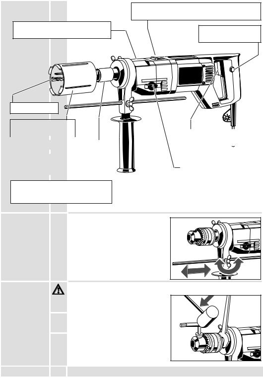
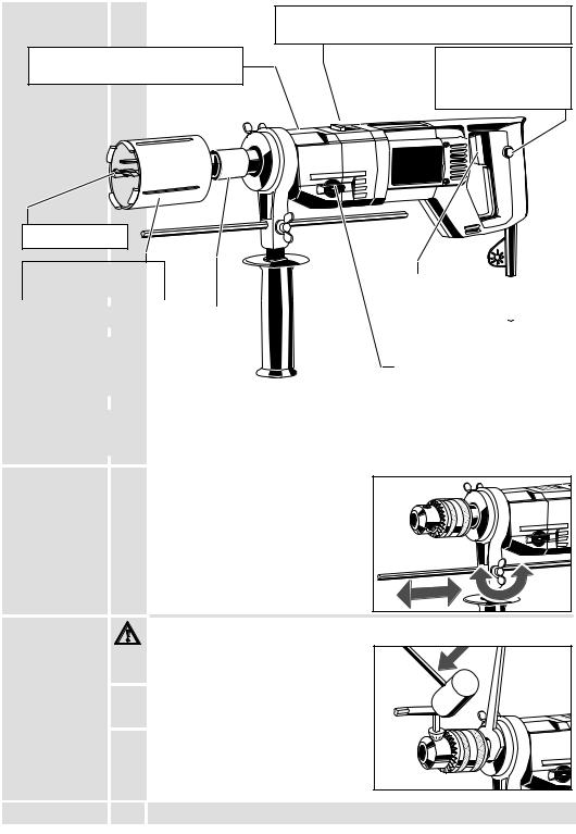
Brief description
Selector lever for switching between drilling and percussion drilling. (only applicable for DSB2E 1500)
Metal gear box ensures long service life.
Centre bit |
1
2 
Lock button for switch locking
Dry diamond core |
|
|
|
|
|
|
cutter |
|
|
Switch trigger for switching the |
|||
|
|
|
|
|||
|
|
|
|
machine on and off, and for |
||
Adaptor reducer |
|
|||||
|
|
smooth starting and varying |
||||
|
|
|
|
speed. |
||
|
|
|
||||
Built–in safety clutch in both gear |
|
|
|
|
||
|
|
|
|
|||
stages prevents rotating of the machine |
|
Gear lever for switching |
||||
in case the core cutter is jammed. |
|
|||||
|
between 1st and 2nd gear. |
|||||
|
|
|
|
|||
|
|
|
|
|
|
|
|
|
|
|
|
|
|
Motor protection device controlled by |
|
|
|
motor load – heat controlled shut-off if |
Modifications: Text, diagrams and data are |
||
overloading is great. |
|
correct at the time of printing. In the interest of |
|
|
continuous improvement of our products, technical |
||
|
|
||
|
|
specifications are subject to alteration without prior |
|
|
|
notice. |
|
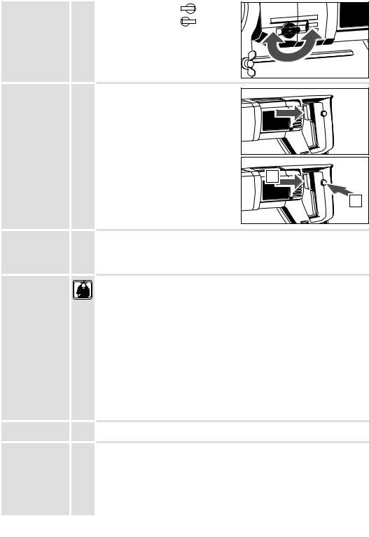
Depth gauge |
For drilling to specific depth, slide the |
|
|
|
depth gauge into the hole provided in the |
|
|
|
handle and fasten it at the required drilling |
|
|
|
depth. |
|
|
|
|
1 |
2 |
Changing the |
Always disconnect the plug from the socket before carrying out any work on the |
three jaw chuck |
machine. |
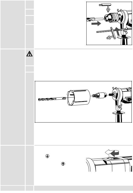
1. Hold the drive shank with the open-jaw spanner.
2. Insert the drill chuck key in the drill chuck and loosen the drill chuck to the left by tapping it lightly with a rubber hammer.
3. Mount the chuck in reverse order.
1
2
ENGLISH |
5 |
DB2E 1500, DSB2E 1500 |
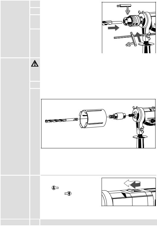
Fitting the working |
1. |
Open chuck by turning. |
tools |
|
|
|
2. |
Insert the working tool |
3. Insert chuck key successively into all 3 holes at the chuck month and tighten clockwise.
4. Insert the hexagonal end of the key into the hexagonal hole in the eccentric cam and rotale clockwise until tight. The chuck is now locked.
Removal of the |
Rotate eccentric cam anticlockwise using |
||
working tools |
key. Open chuck with toothed end of key. |
|
|
|
|||
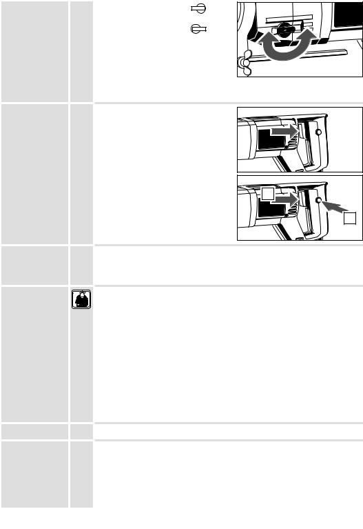
Mounting the |
|
|
|
Always disconnect the plug from the socket before carrying out any work on the |
|||
core cutter |
machine. |
||
(Standard |
|
|
|
system) |
|
|
|
1.Screw down the SDS–plus adapter on the work spindle.
2.Screw down the diamond core cutter on the SDS–plus adapter.
3.Pull back metal sleeve of the SDS–plus adaptor. Push in centre bit (SDS–plus drill bit) rotating it and let go of metal sleeve.
1 |
2 |
|
 Check that the centre bit is bolted properly. It should be movable 5 mm in longitudinal direction.
 The centre bit should surpass the core cutter by at least 5 mm.
 Use SDS–plus drill bits with a diameter of 8 mm.
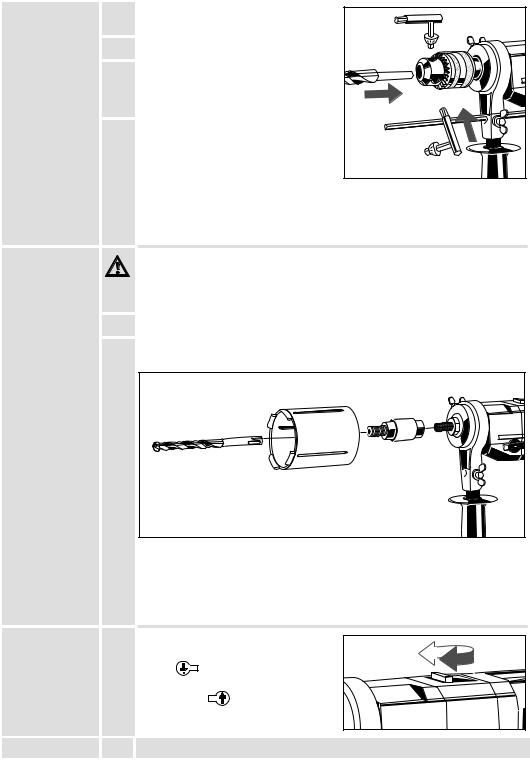
Switching over |
Changeover drilling/hammer drilling with |
|||
drilling |
switch |
|
|
|
percussion |
Drilling: |
Turn arrow towards handle |
||
drilling |
||||
(only applicable |
Hammer Drilling: |
Turn arrow towards |
||
for DSB2E 1500) |
||||
chuck |
|
|
||
|
|
|
||
ENGLISH |
6 |
DB2E 1500, DSB2E 1500 |
Changing gear
Switching the machine on and off
Protection of motor in case of overload
Advice for operation
Maintenance
Gear change lever in position |
2 |
1 : 1st |
|
|
|
gear |
|
|
|
|
|
Gear change lever in position |
1 |
2 |
: 2nd |
1 |
2 |
|
|
||||
|
|
|
|
||
gear. |
|
|
|
|
|
Only change over when machine is slowing down.
Intermittent use
Switching on: Press On-/off switch
Switching off: Release On-/off switch
Continuous use
Switching on: Press the On-/off switch and then the locking button, after that release on-off switch.
Switching off: Press the On-/off switch and then release.
1 |
2 |
Motor protection device controlled by motor load – heat controlled shut-off if overloading is great.
The machine will slowly continue to run in order to cool the motor down. After sufficient cooling machine can be restarted by switching off and on again.
Only switch the percussion mechanism for piercing. Switch off percussoin mechanism as soon as the core cutter grips completely into the material.
To gain a better drill progress take out the centre bit after having reached a depth of about 10–15 mm. Insert core cutter into the existing groove and let machine run up smoothly.
Bore–holes which don’t have to be applied exactly can be drilled without a centre bit. For that purpose apply the core cutter slantingly and put the machine slowly straight when a depth of about 5 mm has been reached. (This is only possible when using short core cutters!)
If drill cores should come loose, take core cutter from the material and remove drill cores.
For best performance the diamond segments should be ”roughed-up” to expose the fragments of diamond:
To expose the diamond fragments rub surface of segments with stone
Further accessories with part numbers are shown in our catalogues.
The ventilation slots of the machine must be kept clear at all times.
Use only AEG accessories and spare parts. Should components need to be exchanged which have not been described, please contact one of our AEG service agents (see our list of guarantee/service addresses).
ENGLISH |
7 |
DB2E 1500, DSB2E 1500 |

Vorwort |
|
Sie sind anspruchsvoll und erwarten Qualität, die Ihnen AEG bietet. |
|
|
|
||||||
|
|
Für Sie haben wir ein haltbares und möglichst sicheres Elektrowerkzeug gebaut. |
|
||||||||
|
|
Bitte lesen Sie vor Inbetriebnahme Ihres Gerätes die Gebrauchsanleitung, um Ihr |
|
||||||||
|
|
Elektrowerkzeug effektiv und gefahrlos nutzen zu können. |
|
|
|
|
|
||||
|
|
Wir sind sicher, daß Sie mit AEG Elektrowerkzeugen von Atlas Copco Ihre richtige |
|
||||||||
|
|
Wahl getroffen haben. |
|
|
|
|
|
|
|
|
|
|
|
|
|
|
|
|
|
|
|
||
Technische |
|
|
DB2E 1500 |
|
|
DSB2E 1500 |
|
|
|
||
Daten |
|
Anschlußspannung |
220–240 |
V . . . |
|
220–240 |
V |
110 |
V |
|
|
|
|
|
|
||||||||
|
|
|
50 |
Hz |
|
50 |
Hz |
50 |
Hz |
|
|
|
|
Nennaufnahme . . . . . . . . . . . |
. . . 1500 |
W . . . |
. |
. . . 1500 |
W . . . |
. . . . 1100 |
W |
|
|
|
|
Leerlaufdrehzahl |
|
min-1 |
|
|
min-1 . . 0–1100 |
min-1 |
|
||
|
|
1. Gang . . . . . . . . . . . . . . . . . |
. 0–1100 |
. . 0–1100 |
|
||||||
|
|
2. Gang . . . . . . . . . . . . . . . . . |
. 0–3000 |
min-1 |
. . 0–3000 |
min-1 . . 0–3000 |
min-1 |
|
|||
|
|
Lastdrehzahl max. |
|
min-1 |
|
|
min-1 |
|
min-1 |
|
|
|
|
1. Gang . . . . . . . . . . . . . . . . . |
. . . . 725 |
. . . . . 725 |
. . . . . 650 |
|
|||||
|
|
2. Gang . . . . . . . . . . . . . . . . . |
. . . 2000 |
min-1 |
. . . . 2000 |
min-1 . . . . 1900 |
min-1 |
|
|||
|
|
Schlagzahl max. . . . . . . . . . . . . . . . . – |
. . . . . . |
. 48000. . |
min-1 |
. . . 48000 |
min-1 |
|
|||
|
|
Bohr-ø in |
|
|
|
|
|
|
|
|
|
|
|
1. Gang . . . . . . . . . . . . . . . . |
. 80–162 |
mm . |
. . 80–162 |
mm . . . 80–152 |
mm |
|
|||
|
|
2. Gang . . . . . . . . . . . . . . . . . |
. . 32–90 |
mm . |
. . . 32–90 |
mm . . . . 32–90 |
mm |
|
|||
|
|
Bohrfutterspannbereich . . . . |
. . . . . . – . |
. . . . . |
. |
. . . . . . – |
mm . . . . . 3–16 |
mm |
|
||
|
|
Bohrspindel . . . . . . . . . . . . . . . |
. . . M18 |
. . . . . |
. |
. . . . M18 |
. . . . . . |
. . . . M18 |
|
|
|
|
|
Spannhals-ø . . . . . . . . . . . . . . |
. . . . . 57 |
mm . |
. 57. . . . . |
mm . . |
. . . . . . 57 |
mm |
|
||
|
|
Gewicht . . . . . . . . . . . . . . . . . . |
. . . . . 3,3 |
kg . . . |
. 3,3. . . . . |
kg . . . |
. . . . . 3,3 |
kg |
|
||
|
|
|
|
|
|
|
|
|
|
|
|
Hinweise für |
J |
Sicherheitshinweise der beiliegenden Broschüre beachten! |
|
|
|
|
|||||
Ihre Sicherheit |
J |
Staub der bei der Bearbeitung von asbesthaltigen Materialien und Gestein mit |
|
||||||||
|
|
||||||||||
|
|
kristalliner Kieselsäure entsteht, ist gesundheitsschädlich. Beachten Sie die |
|
|
|
||||||
|
|
Unfallverhütungsvorschriften VBG 119 der Berufsgenossenschaft. |
|
|
|
|
|||||
|
J |
Beim Arbeiten mit der Maschine stets Schutzbrille tragen. Schutzhandschuhe, festes |
|
||||||||
|
|
und rutschsicheres Schuhwerk und Schürze werden empfohlen. |
|
|
|
|
|||||
|
J |
Gehäuse der Maschine nicht anbohren, da sonst die Schutzisolierung unterbrochen |
|
||||||||
|
|
wird (Klebeschilder verwenden). |
|
|
|
|
|
|
|
|
|
|
J |
Vor allen Arbeiten an der Maschine Stecker aus der Steckdose ziehen. |
|
|
|
||||||
|
|
Maschine nur ausgeschaltet an die Steckdose anschließen. |
|
|
|
|
|||||
|
J |
Anschlußkabel stets vom Wirkungsbereich der Maschine fernhalten. Kabel immer |
|
||||||||
|
|
nach hinten von der Maschine wegführen. |
|
|
|
|
|
|
|
||
|
J |
Stets den Zusatzhandgriff verwenden. |
|
|
|
|
|
|
|
|
|
|
J |
Beim Bohren in Wand, Decke oder Fußboden auf elektrische Kabel, Gasund |
|
||||||||
|
|
Wasserleitungen achten. |
|
|
|
|
|
|
|
|
|
Geräusch- |
|
Der A-bewertete Geräuschpegel des Gerätes beträgt typischerweise: |
|
|
|
||||||
meßwerte |
|
Schalldruckpegel = 102 dB (A). Schalleistungspegel = 115 dB (A). |
|
|
|
||||||
|
|
Gehörschutz tragen! |
|
|
|
|
|
|
|
|
|
|
|
Meßwerte ermittelt entsprechend EN 50 144. |
|
|
|
|
|
|
|
||
Vibrations- |
|
DB2E 1500: Die Hand-Arm Vibration ist typischerweise niedriger als 2,5 m/s2. |
|
||||||||
meßwerte |
|
DSB2E 1500: Die bewertete Beschleunigung beträgt typischerweise 12 m/s2. |
|
|
|
||||||
|
|
Meßwerte ermittelt entsprechend EN 50 144. |
|
|
|
|
|
|
|
||
Verwendung |
|
Der Elektronik-Bohrer DB2E 1500 und der Elektronik-Schlagbohrer DSB2E 1500 ist |
|
||||||||
|
|
speziell einsetzbar zum Bohren mit Diamant-Trockenbohrkronen. |
|
|
|
|
|||||
|
|
Dieses Gerät darf nur wie angegeben bestimmungsgemäß verwendet werden. |
|
||||||||
Netzanschluß |
|
Nur an Einphasen-Wechselstrom und nur an die auf dem Leistungsschild |
|
|
|
||||||
|
|
angegebene Netzspannung anschließen. Anschluß ist auch an Steckdosen ohne |
|
||||||||
|
|
Schutzkontakt möglich, da eine Schutzisolierung nach DIN 57 740/ VDE 0740 bzw. |
|
||||||||
|
|
CEE 20 vorliegt. Die Funkentstörung entspricht der Europanorm EN 55014. |
|
|
|
||||||
|
|
|
|
|
|
|
|
|
|
||
|
|
|
|
|
|
|
|
|
|
|
|
DEUTSCH |
8 |
|
|
|
|
|
DB2E 1500, DSB2E 1500 |
|
|||

Kurzbeschreibung
Metallgetriebekasten für lange
Lebensdauer.
Zentrierbohrer |
Diamantbohrkrone |
SDS-plus Adapter
Eingebaute Sicherheitskupplung in beiden Getriebestufen, verhindert ein Mitdrehen der Maschine bei Verklemmen der Bohrers.
Belastungsabhängiger Motorschutz – thermisch ausgelöstes Abschalten bei hoher Motorüberlastung
Schalthebel zum Umschalten zwischen Bohren und Schlagbohren. (nur bei DSB2E 1500)
Arretierknopf zum
Feststellen des
Schalterdrückers.
12 
Schalterdrücker zum Einund Ausschalten der Maschine und stufenlosem elektronischem ”Gasgeben”.
Schalthebel zum Umschalten zwischen 1. Gang und 2. Gang.
Änderungen: Text, Bild und Daten entsprechen dem technischen Stand zur Zeit des Drucktermins. Änderungen im Sinne der Weiterentwicklung unserer Produkte sind vorbehalten.
Tiefenanschlag |
|
Zum Bohren auf eine bestimmte Tiefe |
|
|
|
|
Tiefenanschlag in die Bohrung am |
|
|
|
|
Handgriff schieben und um die |
|
|
|
|
gewünschte Bohrtiefe (versetzt zum |
|
|
|
|
Bohrer) festklemmen. |
|
|
|
|
1 |
2 |
|
Zahnkranzbohr- |
|
Vor allen Arbeiten an der Maschine Stecker aus der Steckdose ziehen. |
|
|
futter wechseln |
|
|
|
|
|
|
1. Bohrspindel mit Maulschlüssel festhalten. |
|
|
|
|
2. Bohrfutterschlüssel in Bohrfutter stecken |
|
|
|
|
und durch leichten Schlag mit dem |
|
|
|
|
Gummihammer Bohrfutter linksdrehend |
|
|
|
|
lösen. |
|
|
|
|
3. Die Montage des Bohrfutters erfolgt in |
|
|
|
|
umgekehrter Reihenfolge. |
|
|
|
|
|
1 |
2 |
DEUTSCH |
9 |
DB2E 1500, DSB2E 1500 |
||
Einsetzen der |
1. Bohrfutter von Hand durch Verdrehen |
Arbeitswerkzeuge |
öffnen. |
2. Arbeitswerkzeug einsetzen
3. Bohrfutterschlüssel nacheinander in alle drei Bohrungen am Bohrfutterkopf einsetzen und rechtsdrehend festspannen.
4. Mit dem Sechskant des
Borfutterschlüssels den Exzenter rechtsdrehend bis zum Anschlag drehen . Dadurch ist die Spannkraft des Bohrfutters gesichert.
Herausnehmen der Exzenter mit Sechskant des
Arbeitswerkzeuge Bohrfutterschlüssels durch Linksdrehen lösen und Bohrfutter mit Verzahnung des Bohrutterschlüssels öffnen.
Diamantbohr- |
Vor allen Arbeiten an der Maschine Stecker aus der Steckdose ziehen. |
krone montieren |
|
(Standardsystem) |
|
1.SDS-plus-Adapter auf die Arbeitspindel schrauben.
2.Diamantbohrkrone auf den SDS-plus-Adapter schrauben.
3.Metallhülse des SDS-plus-Adapters zurückziehen, Zentrierbohrer (SDS-plus
Bohrer) drehend einschieben und Metallhülse loslassen.
1 |
2 |
 Prüfen ob Zentrierbohrer richtig verriegelt ist, er muß sich in Längsrichtung ca. 5 mm bewegen lassen.
 Der Zentriebohrer sollte die Diamantbohrkrone um mindestens 5 mm überragen.
 SDS-plus Bohrer mit ø 8 mm verwenden.
Umschalten: |
|
Umschalten Bohren-Schlagbohren mit |
Bohren |
|
Schalthebel: |
Schlagbohren |
|
Bohren: |
(nur bei |
|
|
DSB2E 1500) |
|
Pfeilspitze in Richtung Griff stellen |
|
|
Schlagbohren: |
|
|
Pfeilspitze in Richtung Bohrfutter stellen |
DEUTSCH |
10 |
DB2E 1500, DSB2E 1500 |
Gangschaltung
Ein-/Ausschalten
Belastungsabhängiger Motorschutz
Arbeitshinweise
Wartung
Gangschalter in Stellung |
2 |
1 |
: 1. Gang |
Gangschalter in Stellung |
1 |
2 |
: 2. Gang |
1 |
2 |
Nur im Auslauf der Maschine umschalten.
Momentschaltung
Einschalten: Ein-/Ausschalter drücken.
Ausschalten: Ein-/Ausschalter loslassen.
Dauerschaltung |
Einschalten: Ein-/Ausschalter drücken und |
dann Arretierknopf drücken, |
Ein-/Ausschalter loslassen. |
Ausschalten: Ein-/Ausschalter drücken |
und loslassen. |
1 |
2 |
Bei hoher Motorüberlastung wird der thermische Überlastschutz ausgelöst. Die Maschine läuft langsam weiter zum Kühlen der Motorwicklung. Erst nach ausreichender Kühlung ist ein Einschalten der Maschine möglich, hierzu Maschine ausund wieder einschalten.
Das Schlagwerk nur beim Anbohren zuschalten, sobald die Diamantbohrkrone im
Material greift, Schlagwerk abschalten.
Zum Erreichen eines größeren Bohrfortschritts nach ca 10–15 mm Bohrtiefe den Zentrierbohrer herausnehmen, Bohrkrone in vorhandene Rille einsetzen und Maschine langsam anlaufen lassen.
Bohrungen welche nicht exakt angesetzt werden müssen, können ohne
Zentrierbohrer durchgeführt werden.
Hierzu die Bohrkrone schräg ansetzen und ab einer Bohrtiefe von ca. 5 mm die Maschine langsam gerade richten. (Nur bei kurzen Bohrkronen möglich).
Sollten sich Bohrkerne lösen, Bohrkrone aus dem Material herausziehen und Bohrkerne entfernen.
Eine geschärfte Bohrkrone erleichtert die Anwendung und den Bohrfortschritt.
Schärfmöglichkeiten: In Kalksandstein oder in einer Schärfplatte
Weiteres Zubehör mit den Bestellnummern ersehen Sie bitte aus unseren Katalogen.
Stets die Lüftungsschlitze der Maschine sauber halten.
Nur AEG Zubehör und Ersatzteile verwenden. Bauteile, deren Austausch nicht beschrieben wurde, bei einer AEG Kundendienststelle auswechseln lassen
(Broschüre Garantie/Kundendienstadressen beachten).
DEUTSCH |
11 |
DB2E 1500, DSB2E 1500 |

Introduction |
|
Vous avez des exigences et vous voulez de la qualité – une qualité que vous offre |
|||||||
|
|
AEG. |
|
|
|
|
|
|
|
|
|
Nous avons mis au point pour vous un outil électrique de longue durée vous offrant |
|||||||
|
|
un maximum de sécurité. Avant la mise en service de votre appareil, veuillez lire |
|||||||
|
|
attentivement le mode d’emploi afin d’en tirer le plus d’efficacité et d’éviter tout risque |
|||||||
|
|
de danger. |
|
|
|
|
|
|
|
|
|
Nous sommes convaincus qu’avec les outils électriques AEG vous avec fait le choix |
|||||||
|
|
qu’il fallait. |
|
|
|
|
|
|
|
|
|
|
|
|
|
|
|
||
Caractéristiques |
|
|
DB2E 1500 |
|
|
DSB2E 1500 |
|
||
techniques |
|
Tension d’alimentation . . . . 220–240 |
V . . . |
|
220–240 |
V |
110 |
V |
|
|
|
|
|||||||
|
|
|
50 |
Hz |
|
50 |
Hz |
50 |
Hz |
|
|
Puissance absorbée . . . . . . . . |
. . 1500 |
W . . . |
. |
. . . 1500 |
W . . . |
. . . . 1100 |
W |
|
|
Régime à vide |
|
min-1 |
|
|
min-1 . . 0–1100 |
min-1 |
|
|
|
1ère vitesse . . . . . . . . . . . . . . |
0–1100 |
. . 0–1100 |
|||||
|
|
2ème vitesse . . . . . . . . . . . . . |
0–3000 |
min-1 |
. . 0–3000 |
min-1 |
. . 0–3000 |
min-1 |
|
|
|
Vitesse en charge |
|
min-1 |
|
|
min-1 |
|
min-1 |
|
|
1ère vitesse . . . . . . . . . . . . . . |
. . . 725 |
. . . . . 725 |
. . . . . 650 |
||||
|
|
2ème vitesse . . . . . . . . . . . . . |
. . 2000 |
min-1 |
. . . . 2000 |
min-1 . . . . 1900 |
min-1 |
||
|
|
Perçage à percussion . . . . . . . |
. . . . . – |
. . . . . . |
. 48000. . |
min-1 |
. . . 48000 |
min-1 |
|
|
|
Ø de perçage dans |
|
|
|
|
|
|
|
|
|
1ère vitesse . . . . . . . . . . . . . |
80–162 |
mm . |
. . 80–162 |
mm . . . 80–152 |
mm |
||
|
|
2ème vitesse . . . . . . . . . . . . . |
. 32–90 |
mm . |
. . . 32–90 |
mm . . . . 32–90 |
mm |
||
|
|
Plage de serrage du mandrin |
. . . . . – |
. . . . . . |
. |
. . . . . . – |
mm . . . . . 3–16 |
mm |
|
|
|
Arbre de forage . . . . . . . . . . . . |
. . M18 |
. . . . . |
. |
. . . . M18 |
. . . . . |
. . . . . M18 |
|
|
|
Ø du collier de serrage . . . . . . |
. . . . 57 |
mm . |
. 57. . . . . |
mm . |
. . . . . . . 57 |
mm |
|
|
|
Poids . . . . . . . . . . . . . . . . . . . . . |
. . . . 3,3 |
kg . . . |
. 3,3. . . . . |
kg . . |
. . . . . . 3,3 |
kg |
|
|
|
|
|
|
|
|
|
|
|
Conseils de |
J Respecter les instructions de sécurité se trouvant dans le prospectus ci-joint. |
|
|||||||
sécurité |
J La poussière qui se dégage lors de l’usinage des matériaux contenant de l’amiante |
||||||||
|
|||||||||
|
|
et des pierres contenant de l’acide silicique cristallin porte atteinte à la santé. |
|
||||||
JToujours porter des lunettes protectrices lorsqu’on travaille avec la machine. Des gants de sécurité et un masque de protection sont recommandés.
JNe pas percer le carter de la machine; ceci pourrait entraîner une détérioration de l’isolation de protection (utiliser des autocollants).
JAvant tous travaux sur la machine extraire la fiche de la prise de courant.
Ne raccorder la machine au réseau que si l’interrupteur est en position arrêt.
JLe câble d’alimentation doit toujours se trouver en dehors du champ d’action de la machine. Toujours maintenir le câble d’alimentation à l’arrière de la machine.
JUtiliser toujours la poignée complémentaire.
JLors du perçage dans les murs, les plafonds ou les planchers, toujours faire attention aux câbles électriques et aux conduites de gaz et d’eau.
Mesure de bruit |
|
Les mesures réelles (A) des niveaux de bruit de la machine sont: |
|
|
|
|
Intensité de bruit = 102 dB (A). Niveau de bruit = 115 dB (A). |
|
|
|
|
Toujours porter des casques protecteurs! |
|
|
|
|
Valeurs de mesures obtenues conformément à la norme européenne 50 144. |
|
|
Valeur de |
|
DB2E 1500: La vibration de l’avant–bras est en–dessous de 2,5 m/s2. |
|
|
vibration |
|
DSB2E 1500: L’accélération réelle mesurée est 12 m/s2. |
|
|
mesurée |
|
Valeurs de mesures obtenues conformément à la norme européenne 50 144. |
|
|
Utilisation |
|
La perceuse électronique DB2E 1500 et la perceuse électronique à percussion |
|
|
|
|
DSB2E 1500 sont particulièrement appropriées pour les travaux de perçage avec |
|
|
|
|
couronnes diamantées de perçage à sec. |
|
|
|
|
Comme déjà indiqué, cette machine n’est conçue que pour une utilisation normale. |
|
|
Branchement |
|
Nos machines fonctionnent uniquement sur courant alternatif monophasé. S’assurer |
|
|
secteur |
|
que la tension du réseau correspond effectivement à celle indiquée sur la plaque |
|
|
|
|
signalétique de la machine. Le branchement sur une prise de courant sans mise à |
|
|
|
|
terre est possible du fait de la double isolation selon normes DIN 57 740/VDE 0740 |
|
|
|
|
et CEE 20. Antiparasitage selon normes européennes EN 55014. |
|
|
|
|
|
|
|
FRANÇAIS |
12 |
DB2E 1500, DSB2E 1500 |
|
|
Description |
Commutateur de sélection entre perçage et perçage à |
||||
|
|
|
percussion. (uniquement sur DSB2E 15000) |
||
|
|
|
|
|
|
|
Carter d’engrenage en métal pour |
|
|
Bouton de blocage de |
|
|
|
||||
|
une longue durée de vie. |
|
|
l’interrupteur |
|
Foret de |
centrage |
1
2 
Couronne diamantée |
|
|
|
|
|
|
|
|
Commutateur marche/arrêt et |
|
|
Adaptateur SDS–Plus |
|
pour démarrage doux réglable |
|
||
|
|
|
|
||
Accouplement de sécurité intégré |
|
|
|
||
pour les deux vitesses, empêche que la |
Sélecteur de vitesse 1 et 2 . |
|
|||
machine tourne lorsque la couronne de |
|
||||
|
|
|
|||
perçage se trouve coincée. |
|
|
|
||
Protection du moteur des surcharges – |
Modifications: Les textes, les illustrations et les |
|
|||
déclenchement thermique en cas d’une |
données techniques correspondent à la situation |
|
|||
au moment de l’impression. Toutes modifications |
|
||||
trop grande surcharge du moteur. |
|
||||
techniques sont réservées dans le cadre du |
|
||||
|
|
|
développement technique permanent. |
|
|
Butée de |
|
Afin d’effectuer des perçages d’une |
|
|
|
profondeur |
|
profondeur déterminée, introduire la butée |
|
|
|
|
|
de profondeur dans l’alésage se trouvant |
|
|
|
|
|
sur la poignée et la serrer dans la position |
|
|
|
|
|
désirée (par rapport au foret). |
|
|
|
|
|
|
1 |
2 |
|
Remplacement |
|
Avant tous travaux sur la machine extraire la fiche de la prise de courant. |
|
|
|
du mandrin de |
|
|
|
|
|
serrage à |
1. |
Maintenir l’arbre moteur à l’aide de la clé à |
|
|
|
couronne dentée |
|
|
|
||
|
|
fourche. |
|
|
|
|
2. Introduire la clé dans le mandrin et le |
|
|
|
|
|
|
débloquer en frappant dessus légèrement |
|
|
|
|
|
(vers la gauche) avec un maillet en |
|
|
|
|
|
caoutchouc. |
|
|
|
|
3. Le montage du mandrin de serrage |
|
|
|
|
|
|
s’effectue dans l’ordre inverse. |
|
|
|
|
|
|
|
1 |
2 |
FRANÇAIS |
13 |
|
DB2E 1500, DSB2E 1500 |
||
Emploi des |
1. Ouvrir le mandrin manuellement par |
différents outils |
déblocage. |
2. Mettre en place l’outil correspondant.
|
3. |
Introduire systématiquement la clé de |
|
|
serrage et serrer en tournant vers la droite. |
|
4. |
Avec l’hexagon de la clé tourner |
|
|
l’excentrique à droite jusqu’à la butée . |
|
|
Ainsi la sécunté de serrage est assurée. |
Enlèvement des |
|
Desserrer l’excentrique en tournant |
outils |
|
l’hexagon de la clé vers la gauche et ouvrir |
|
|
le mandrin par la denture de la clè. |
Montage de la |
|
Avant tous travaux sur la machine extraire la fiche de la prise de courant. |
couronne |
|
|
diamantée |
|
|
(Système |
1. |
Visser l’adaptateur SDS–Plus sur l’arbre moteur. |
standard) |
|
|
2.Visser la couronne diamantée sur l’adaptateur SDS–Plus.
3.Retirer la douille métallique de l’adaptateur SDS–Plus, introduire par un mouvement de rotation le foret de centrage (foret SDS–Plus) et relâcher la douille métallique.
1 |
2 |
|
 S’assurer que l’outil est effectivement verrouillé correctement. On doit pouvoir le faire bouger d’environ 5 mm dans le sens longitudinal.
 Le foret de centrage devrait dépasser la couronne diamantée de 5 mm au moins.
 Utiliser foret SDS–Plus ø 8 mm.
Commutation |
Commutation perçage / perçage |
|
|
|
|||||||
perçage |
percussion avec commutateur |
|
|
|
|||||||
perçage à |
Percage: |
|
|
Pointe de flèche en |
|
|
|
||||
percussion |
|
|
|
|
|
||||||
(uniquement sur |
direction de la poignée |
|
|
|
|
||||||
DSB2E 1500) |
Perçage percussion: |
|
|
|
Pointe de flèche |
|
|
|
|||
|
|
|
|
|
|
|
|||||
|
en direction du mandrin |
|
|
|
|
||||||
|
|
|
|
|
|
|
|
|
|
|
|
FRANÇAIS |
14 |
DB2E 1500, DSB2E 1500 |

Changement de vitesse
Mise en marche/arrêt
Protection de surcharge du moteur
Conseils pratiques
Entretien
Sélecteur de vitesse en position |
2 |
1 : |
|
|
|
première |
|
|
|
|
|
Sélecteur de vitesse en position |
1 |
2 |
: |
1 |
2 |
|
|
||||
|
|
|
|
||
deuxième |
|
|
|
|
|
Ne commuter que lorsque la machine est |
|
|
|||
en fin de rotation. |
|
|
|
|
|
Marche momentanée |
|
|
|
|
|
Mise en marche: appuyer sur l’interrupteur |
|
|
|||
Marche/Arrêt |
|
|
|
|
|
Arrêt: lâcher l’interrupteur Marche/Arrêt |
|
|
|||
Marche continue
Mise en marche: appuyer d’abord sur l’interrupteur marche/arrêt puis sur le
bouton de blocage, lâcher l’interrupteur marche/arrêt.
Arrêt: appuyer sur l’interrupteur marche/arrêt et lâcher.
1
2
Surcharge de courte durée du moteur.
La machine continue à marcher lentement pour refroidir le bobinage du moteur. Il n’est possible de remettre la machine en marche qu’après un refroidissement suffisant; pour cela, arrêter et remettre la machine en marche.
Enclencher le mécanisme de percussion seulement au départ de l’opération de perçage; dès que la couronne diamantée prend dans le matériau, déclencher le mécanisme de percussion.
Afin d’obtenir une progression de perçage plus élevée, enlever le foret de centrage après avoir atteint une profondeur d’alésage d’environ 10 à 15 mm, ensuite introduire la couronne de forage dans la rainure existante et mettre la machine en marche à une vitesse modérée.
Pour des perçages sans précision particulière, il est possible de travailler sans foret de centrage. Pour cela, incliner légèrement la couronne diamantée au départ de l’opération, puis, dès que la profondeur de 5 mm est atteinte, redresser lentement la machine. (Ceci n’est possible que pour des couronnes diamantées courtes.)
Lorsqu’il y a des carottes se détachant du matériau, retirer la couronne diamantée du matériau et enlever celles–ci..
Une couronne diamantée affûtée facilite l’utilisation de la machine et la progression du travail. Affûtage possible dans des briques de sable calcaire ou dans une plaque d’affûtage.
Pour d’autres accessoires, consulter notre catalogue.
Tenir toujours propre les orifices de ventilation de la partie moteur.
N’utiliser que des pièces et accessoires AEG. Pour des pièces dont l’échange n’est pas décrit, s’adresser de préférence aux stations de service après-vente Atlas
Copco (voir brochure Garantie/Adresses des stations de service après-vente).
FRANÇAIS |
15 |
DB2E 1500, DSB2E 1500 |

Premessa |
|
La vostra richiesta ed aspettativa è quella di acquistare merce d’elevata qualità - |
|||||||
|
|
qualità offerta da AEG. |
|
|
|
|
|
|
|
|
|
Noi costruiamo per voi utensili elettrici durevoli e affidabili. |
|
|
|
||||
|
|
Si prega di leggere attentamente le istruzione al primo utilizzo cosicché si possa |
|||||||
|
|
utilzzare l’utensile elettrico in modo più sicuro e corretto. |
|
|
|
||||
|
|
Siamo sicuri che acquistare gli utensili elettrici di AEG sia la scelta migliore. |
|
||||||
|
|
|
|
|
|
|
|
||
Dati tecnici |
|
|
DB2E 1500 |
|
|
DSB2E 1500 |
|
||
|
|
Gamma di tensione . . . . . . |
220–240 |
V . . . |
|
220–240 |
V . . . |
. . . . . . 110 |
V |
|
|
|
50 |
Hz |
|
50 |
Hz |
50 |
Hz |
|
|
Potenza assorbita . . . . . . . . . |
. . . 1500 |
W . . . |
. |
. . . 1500 |
W . . . |
. . . . 1100 |
W |
|
|
Numero di giri a vuoto |
|
min-1 |
|
|
min-1 . . 0–1100 |
min-1 |
|
|
|
1. velocità . . . . . . . . . . . . . . . |
. 0–1100 |
. . 0–1100 |
|||||
|
|
2. velocità . . . . . . . . . . . . . . . |
. 0–3000 |
min-1 |
. . 0–3000 |
min-1 |
. . 0–3000 |
min-1 |
|
|
|
Numero di giri a carico, max. |
|
min-1 |
|
|
min-1 |
|
min-1 |
|
|
1. velocità . . . . . . . . . . . . . . . |
. . . . 725 |
. . . . . 725 |
. . . . . 650 |
||||
|
|
2. velocità . . . . . . . . . . . . . . . |
. . . 2000 |
min-1 |
. . . . 2000 |
min-1 . . . . 1900 |
min-1 |
||
|
|
Percussione a pieno carico . |
. . . . . . – |
. . . . . . |
. 48000. . |
min-1 |
. . . 48000 |
min-1 |
|
|
|
ø Foratura in |
|
|
|
|
|
|
|
|
|
1. velocità . . . . . . . . . . . . . . |
. 80–162 |
mm . |
. . 80–162 |
mm . . . 80–152 |
mm |
||
|
|
2. velocità . . . . . . . . . . . . . . . |
. . 32–90 |
mm . |
. . . 32–90 |
mm . . . . 32–90 |
mm |
||
|
|
Capacità mandrino . . . . . . . . |
. . . . . . – . |
. . . . . |
. |
. . . . . . – |
mm . . . . . 3–16 |
mm |
|
|
|
Attaco mandrino . . . . . . . . . . . |
. . . M18 |
. . . . . |
. |
. . . . M18 |
. . . . . |
. . . . . M18 |
|
|
|
ø collarino di fissaggio . . . . . |
. . . . . 57 |
mm . |
. 57. . . . . |
mm . |
. . . . . . . 57 |
mm |
|
|
|
Peso . . . . . . . . . . . . . . . . . . . . |
. . . . . 3,3 |
kg . . . |
. 3,3. . . . . |
kg . . |
. . . . . . 3,3 |
kg |
|
|
|
|
|
|
|||||
Norme di |
J Si prega di leggere con attenzione le istruzioni riguardanti la sicurezza, nel volantino |
||||||||
sicurezza |
|
allegato. |
|
|
|
|
|
|
|
JTenere presente che la polvere che si solleva durante la lavorazione di materiali con amianto, pietra silice cristallizzata, é dannosa alla salute. Attenersi sempre alle prescrizioni di sicurezza vigenti in materia.
JDurante l’uso dell’apparecchio utilizzare sempre gli occhiali di protezione. Inoltre si consiglia di usare sistemi di protezione per la respirazione e per l’udito, oltre ai guanti di protezione.
JEvitare di forare la carcassa dell’utensile per non danneggiare l’isolamento. (Utilizzare placchette adesive).
JPrima di effettuare qualsiasi lavoro sulla macchina togliere la spina dalla presa di corrente.
Inserire la spina solo con interruttore su posizione “OFF”.
JTenere sempre lontano il cavo di collegamento dall’area di lavoro dell’attrezzo.
JUtilizzare sempre l’impugnatura laterale.
JForando pareti, soffitti o pavimenti, si faccia attenzione ai cavi elettrici e alle condutture dell’acqua e del gas.
Livello di |
|
La misurazione A del livello di rumorosità di un utensile è di solito: |
|
|
rumorosità |
|
Livello di rumorosità = 102 dB (A). Potenza della rumorosità = 115 dB (A). |
|
|
|
|
Utilizzare le protezioni per l’udito! |
|
|
|
|
Valori misurati conformemente alla norma EN 50 144. |
|
|
Livello di |
|
DB2E 1500: Le vibrazioni sull’elemento mano-braccio di solito sono inferiori |
|
|
vibrazione |
|
a 2.5 m/s2. |
|
|
|
|
DSB2E 1500: La misurazione dell’accellerazione di solito è 12 m/s2. |
|
|
|
|
Valori misurati conformemente alla norma EN 50 144. |
|
|
Possibilità’ di |
|
Tanto il trapano elettronico DB2E 1500 quanto il trapano elettronico a percussione |
|
|
utilizzo |
|
DSB2E 1500 sono disegnati per trapanare con punte diamantate per tagli a secco. |
|
|
|
|
Utilizzare il prodotto solo per l’uso per cui è previsto. |
|
|
Collegamento |
|
Alimentazione dell’utensile: corrente alternata monofase. Importante: la tensione |
|
|
alla rete |
|
della rete deve corrispondere a quella riportata sulla targhetta dell’utensile. Il |
|
|
|
|
collegamento é possibile anche con prese non munite di contatto di protezione: é |
|
|
|
|
previsto infatti un isolamento di protezione conforme a norme DIN 57740/VDE 0740 |
|
|
|
|
(CEE 20). La schermatura contro i radiodisturbi é conforme alla norma |
|
|
|
|
europea EN 55014. |
|
|
|
|
|
|
|
ITALIANO |
16 |
DB2E 1500, DSB2E 1500 |
|
|
Breve indicazione
Levetta di commutazione per selezionare:
foratura, foratura a percussione. (solo per DSB2E 1500)
La carcassa ingranaggi in metallo assicura una lunga durata dell’utensile.
Punta da centri |
1
2 
Pulsante di arresto in posizione dell’interruttore principale a grilletto.
Corona a forare |
|
|
|
|||
diamantata |
|
|
Interruttore principale a |
|||
|
|
|
|
|
grilletto per accendere e |
|
|
|
|
|
|||
Adattatore SDS Plus |
|
|
spegnere l’utensile e per |
|||
|
|
un’accelerazione elettronica |
||||
|
|
|
|
|
||
|
|
|
|
|
continua. |
|
Frizione di sicurezza in entrambe le |
||||||
|
|
|||||
|
|
|||||
parti degli ingranaggi per prevenire la |
|
Levetta di commutazione per il |
||||
rotazione della macchina nel caso in cui |
|
|||||
|
passaggio dalla 1ª alla 2ª |
|||||
la punta si blocchi. |
|
|||||
|
velocità. |
|||||
|
|
|
|
|
||
|
|
|
|
|
||
|
|
|
||||
|
|
|
|
|
|
|
Protezione del motore contro il |
Modifiche: Testo, figure e dati corrispondono allo |
|||||
sovraccarico, disinserimento termico in |
standard tecnico aggiornato all’epoca della |
|||||
stampa. Ci riserviamo pertanto eventuali modifiche |
||||||
caso di sovraccarico del motore. |
||||||
tecniche dovute all’ulteriore sviluppo dei nostri |
||||||
|
|
|
|
prodotti. |
||
|
|
|
|
|
|
|
Limitatore di |
Per trapanare all profondità desiderata, |
|
profondità |
inserire il misuratore della profondità |
|
|
nell’apposita fessura nell’impugnatura e |
|
|
fissare la profondità desiderata. |
|
|
1 |
2 |
Sostituzione del |
Prima di effettuare qualsiasi lavoro sulla macchina togliere la spina dalla presa di |
mandrino con |
corrente. |
chiave a |
1. Tenere fermo con la chiave fissa SW 17 |
cremagliera |
|
|
l’albero portamandrino. |
2. Tenere con la chiave il mandrino e batterre leggermente con un martelletto di gomma ruotando verso sinistra e svitando.
3. Il montaggio avviene effettuando le stesse operazioni in sequenza inversa.
1
2
ITALIANO |
17 |
DB2E 1500, DSB2E 1500 |
 Loading...