


BKS 18BL
Original instructions Originalbetriebsanleitung Notice originale Istruzioni originali Manual original
Manual original
Oorspronkelijke gebruiksaanwijzing
Original brugsanvisning Original bruksanvisning Bruksanvisning i original Alkuperäiset ohjeet Πρωτότυπο οδηγιών χρήσης Orijinal işletme talimatı Původním návodem k používání Pôvodný návod na použitie
Instrukcją oryginalną Eredeti használati utasítás Izvirna navodila Originalne pogonske upute Instrukcijām oriģinālvalodā Originali instrukcija Algupärane kasutusjuhend
Оригинальное руководство по эксплуатации
Оригинално ръководство за експлоатация
Instrucţiuni de folosire originale
Оригинален прирачник за работа Оригінал інструкції з експлуатації
ﺔﻳﻠﺻﻷﺍ ﺕﺎﻣﻳﻠﻌﺗﻟﺍ
1

ENGLISH |
1 |
2 |
3 |
Picture section |
|
|
|
with operating description and functional description |
|
DEUTSCH |
1 |
2 |
3 |
Bildteil |
|
|
|
mit Anwendungsund Funktionsbeschreibungen |
|
FRANÇAIS |
1 |
2 |
3 |
Partie imagée |
|
|
|
avec description des applications et des fonctions |
|
ITALIANO |
1 |
2 |
3 |
Sezione illustrata |
|
|
|
con descrizione dell'applicazione e delle funzioni |
|
ESPAÑOL |
1 |
2 |
3 |
Sección de ilustraciones |
|
|
|
con descripción de aplicación y descripción funcional |
|
PORTUGUES |
1 |
2 |
3 |
Parte com imagens |
|
|
|
explicativas contendo descrição operacional e funcional |
|
NEDERLANDS |
1 |
2 |
3 |
Beeldgedeelte |
|
|
|
met toepassingsen functiebeschrijvingen |
|
DANSK |
1 |
2 |
3 |
Billeddel |
|
|
|
med anvendelsesog funktionsbeskrivelser |
|
NORSK |
1 |
2 |
3 |
Bildedel |
|
|
|
med bruksog funksjonsbeskrivelse |
|
SVENSKA |
1 |
2 |
3 |
Bilddel |
|
|
|
med användningsoch funktionsbeskrivning |
|
SUOMI |
1 |
2 |
3 |
Kuvasivut |
|
|
|
käyttöja toimintakuvaukset |
|
ΕΛΛΗΝΙΚΑ |
1 |
2 |
3 |
Τμήμα εικόνων |
|
|
|
με περιγραφές χρήσης και λειτουργίας |
|
TÜRKÇE |
1 |
2 |
3 |
Resim bölümü |
|
|
|
Uygulama ve fonksiyon açıklamaları ile birlikte |
|
ČESKY |
1 |
2 |
3 |
Obrazová část |
|
|
|
s popisem aplikací a funkcí |
|
SLOVENSKY |
1 |
2 |
3 |
Obrazová časťs popisom aplikácií a funkcií |
|
|
|
|
|
POLSKI |
1 |
2 |
3 |
Część rysunkowa z opisami zastosowania i działania |
|
|
|
|
|
MAGYAR |
1 |
2 |
3 |
Képes részalkalmazásiés működési leírásokkal |
|
|
|
|
|
SLOVENSKO |
1 |
2 |
3 |
Del slikez opisom uporabe in funkcij |
|
|
|
|
|
HRVATSKI |
1 |
2 |
3 |
Dio sa slikamasa opisima primjene i funkcija |
|
|
|
|
|
LATVISKI |
1 |
2 |
3 |
Attēla daļa ar lietošanas un funkciju aprakstiem |
|
|
|
|
|
LIETUVIŠKAI |
1 |
2 |
3 |
Paveikslėlio dalissu vartojimo instrukcija ir funkcijų aprašymais |
|
|
|
|
|
EESTI |
1 |
2 |
3 |
Pildiosa kasutusjuhendi ja funktsioonide kirjeldusega |
|
|
|
|
|
РУССКИЙ |
1 |
2 |
3 |
Раздел иллюстрацийс описанием эксплуатации и функций |
|
|
|
|
|
БЪЛГАРСКИ |
1 |
2 |
3 |
Част със снимки с описания за приложение и функции |
|
||||
ROMÂNIA |
1 |
2 |
3 |
Secvenţa de imagine cu descrierea utilizării şi a funcţionării |
|
|
|
|
|
МАКЕДОНСКИ |
1 |
2 |
3 |
Дел со сликисо описи за употреба и функционирање |
|
|
|
|
|
УКРАЇНСЬКА |
1 |
2 |
3 |
Частина з зображеннями з описом робіт та функцій |
|
|
|
|
|
ﻲﺑﺭﻋ |
1 |
2 |
3 |
ﻲﻔﻳﻅﻭﻟﺍﻭ ﻲﻠﻳﻐﺷﺗﻟﺍ ﻑﺻﻭﻟﺍ ﻪﺑ ﺩﺟﻭﻳ ﺭﻭﺻﻟﺍ ﻡﺳﻗ |
|
|
|
|
2
4
4
4
4
4
4
4
4
4
4
4
4
4
4
4
4
4
4
4
4
4
4
4
4
4
4
4
4
Text section with Technical Data, important Safety and Working Hints |
|
26 |
and description of Symbols |
||
Textteil mit Technischen Daten, wichtigen Sicherheitsund Arbeitshinweisen |
|
29 |
und Erklärung der Symbole. |
||
Partie textuelle avec les données techniques, les consignes importantes de sécurité et de travail ainsi que |
|
32 |
l’explication des pictogrammes. |
||
Sezione testo con dati tecnici, importanti informazioni sulla sicurezza e sull‘utilizzo, |
|
35 |
spiegazione dei simboli. |
||
Sección de texto con datos técnicos, indicaciones importantes de seguridad y trabajo y explicación de los símbolos. |
|
38 |
Parte com texto explicativo contendo Especifi cações técnicas, Avisos de segurança e de operação e a Descrição |
|
41 |
dos símbolos. |
||
Tekstgedeelte met technische gegevens, belangrijke veiligheidsen arbeidsinstructies en verklaring van de |
|
44 |
symbolen. |
||
Tekstdel med tekniske data, vigtige sikkerhedsog arbejdsanvisninger |
|
47 |
og symbolforklaring. |
||
Tekstdel med tekniske data, viktige sikkerhetsog arbeidsinstruksjoner |
|
50 |
og forklaring av symbolene. |
||
Textdel med tekniska informationer, viktiga säkerhetsoch användningsinstruktioner |
|
53 |
samt symbolförklaringar. |
||
Tekstisivut: tekniset tiedot, tärkeät turvallisuusja työskentelyohjeet |
|
56 |
sekä merkkien selitykset. |
||
Τμήμα κειμένου με τεχνικά χαρακτηριστικά, σημαντικές υποδείξεις ασφαλείας |
|
59 |
και εργασίας και εξήγηση των συμβόλων. |
||
Teknik bilgileri, önemli güvenlik ve çalışma açıklamalarını ve de sembollerin açıklamalarını |
|
62 |
içeren metin bölümü. |
||
Textová část s technickými daty, důležitými bezpečnostními a pracovními pokyny |
|
65 |
a s vysvětlivkami symbolů |
||
Textová časť s technickými dátami, dôležitými bezpečnostnými a pracovnými pokynmi |
|
68 |
a s vysvetlivkami symbolov |
||
Część opisowa z danymi technicznymi, ważnymi wskazówkami dotyczącymi bezpieczeństwa i pracy oraz |
|
71 |
objaśnieniami symboli. |
||
Szöveges rész műszaki adatokkal, fontos biztonságiés munkavégzési útmutatásokkal, valamint a szimbólumok |
|
74 |
magyarázata. |
||
Del besedila s tehničnimi podatki, pomembnimi varnostnimi opozorili in delovnimi navodili |
|
77 |
in pojasnili simbolov. |
||
Dio štiva sa tehničkim podacima, važnim sigurnosnim i radnim uputama |
|
80 |
i objašnjenjem simbola. |
||
Teksta daļa ar tehniskajiem parametriem, svarīgiem drošības un darbības norādījumiem, |
|
83 |
simbolu atšifrējumiem. |
||
Teksto dalis su techniniais duomenimis, svarbiomis saugumo ir darbo instrukcijomis |
|
86 |
bei simbolių paaiškinimais. |
||
Tekstiosa tehniliste näitajate, oluliste ohutusja tööjuhenditega |
|
89 |
ning sümbolite kirjeldustega. |
||
Текстовый раздел, включающий технические данные, важные рекомендации по безопасности и |
|
92 |
эксплуатации, а также описание используемых символов. |
||
Част с текст с технически данни, важни указания за безопасност и работа |
|
95 |
и разяснение на символите. |
||
Porţiune de text cu date tehnice, indicaţii importante privind siguranţa şi modul de lucru |
|
98 |
şi descrierea simbolurilor. |
||
Текстуален дел со Технички карактеристики, важни безбедносни и работни упатства |
|
101 |
и објаснување на симболите. |
||
Текстова частина з технічними даними, важливими вказівками з техніки безпеки та експлуатації |
|
104 |
і поясненням символів. |
||
ﺯﻭﻣﺭﻟﺍ ﻑﺻﻭﻭ ﻝﻣﻌﻟﺍﻭ ﺔﻣﻼﺳﻠﻟ ﺔﻣﺎﻬﻟﺍ ﺢﺋﺎﺻﻧﻟﺍﻭ ﺔﻳﻧﻔﻟﺍ ﺕﺎﻧﺎﻳﺑﻟﺎﺑ ﺩﻭﺯﻣﻟﺍ ﻲﺻﻧﻟﺍ ﻡﺳﻘﻟﺍ |
111 |
|
|
|
|
|
|
|
|
3 |
|
|
||
17 |
12 |
START |
|
|
STOP |
20 |
15 |
|
8 |
14 |
16 |
16 |
90°
10 |
6 |
21
|
|
|
|
|
|
|
|
|
|
|
|
|
|
|
|
4 |
|
|
|
|
5 |
||
|
|
|
|
|
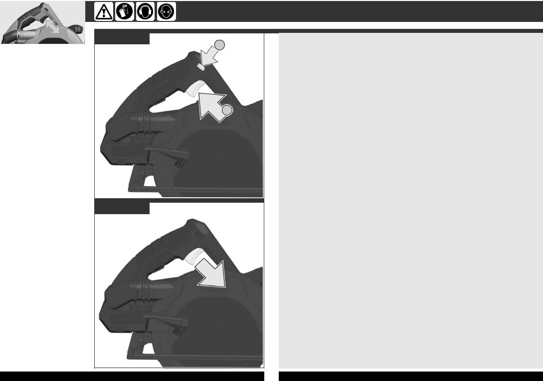
Remove the battery pack before starting any work on the

 machine.


 Vor allen Arbeiten an der
 Maschine den Wechselakku herausnehmen
Avant tous travaux sur la machine retirer l’accu interchangeable.
Prima di iniziare togliere la batteria dalla macchina.
Retire la batería antes de comenzar cualquier trabajo en la máquina.
Antes de efectuar qualquer intervenção na máquina retirar o bloco acumulador.
Voor alle werkzaamheden aan de machine de akku verwijderen.
Ved arbejde inden i maskinen, bør batteriet tages ud.
Ta ut vekselbatteriet før du arbeider på maskinen
Drag ur batteripaket innan arbete utföres på maskinen.
Tarkista pistotulppa ja verkkojohto mahdollisilta vauriolta. Viat saa korjata vain alan erikoismies.
Рсйн брь кЬие есгбуЯб уфз мзчбнЮ бцбйсеЯфе фзн бнфбллбкфйкЮ мрбфбсЯб.
Aletin kendinde bir çalışma yapmadan önce kartuş aküyü çıkarın.
Před zahájením veškerých prací na vrtacím šroubováku vyjmout výměnný akumulátor.
Pred každou prácou na stroji výmenný akumulátor vytiahnuť.
Przed przystąpieniem do jakichkolwiek prac na elektronarzędziu należy wyjąć wkładkę akumulatorową.
Karbantartás, javítás, tisztítás, stb. előtt az akkumulátort ki kell venni a készülékből.
Pred deli na stroju izvlecite izmenljivi akumulator.
Prije svih radova na stroju izvaditi bateriju za zamjenu.
Pirms mašīnai veikt jebkāda veida apkopes darbus, ir jāizņem ārā akumulātors.
Prieš atlikdami bet kokius darbus įrenginyje, išimkite keičiamą akumuliatorių.
Enne kõiki töid masina kallal võtke vahetatav aku välja.
Bыньте аккумулятор из машины перед проведением с ней каких-либо манипуляций.
Преди започване на каквито е да е работи по машината извадете акумулатора.
Scoateţi acumulatorul înainte de a începe orice intervenţie pe maşină.
Отстранете ја батеријата пред да започнете да ја користите машината.
Перед будь-якими роботами на машині вийняти змінну акумуляторну батарею.
.ﺯﺎﻬﺟﻟﺍ ﻰﻠﻋ ﻝﺎﻣﻋﺃ ﻱﺃ ﻲﻓ ءﺩﺑﻟﺍ ﻝﺑﻗ ﺔﻳﺭﺎﻁﺑﻟﺍ ﺔﻣﺯﺣ ﺔﻟﺍﺯﺈﺑ ﻡﻗ
6
1
2
click
1
2
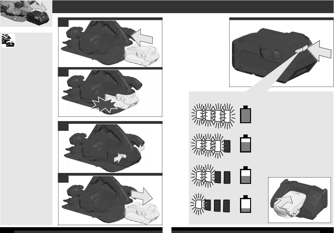
75-100 %
50-75 %
25-50 %
0-25 %
7
1 |
4 |
2 |
5 |
1
2
|
EN 847-1 |
3 |
6 |
8 |
|
|
|
9 |
|
|
1 |
2 |
0 - 64 mm |
3 |
10
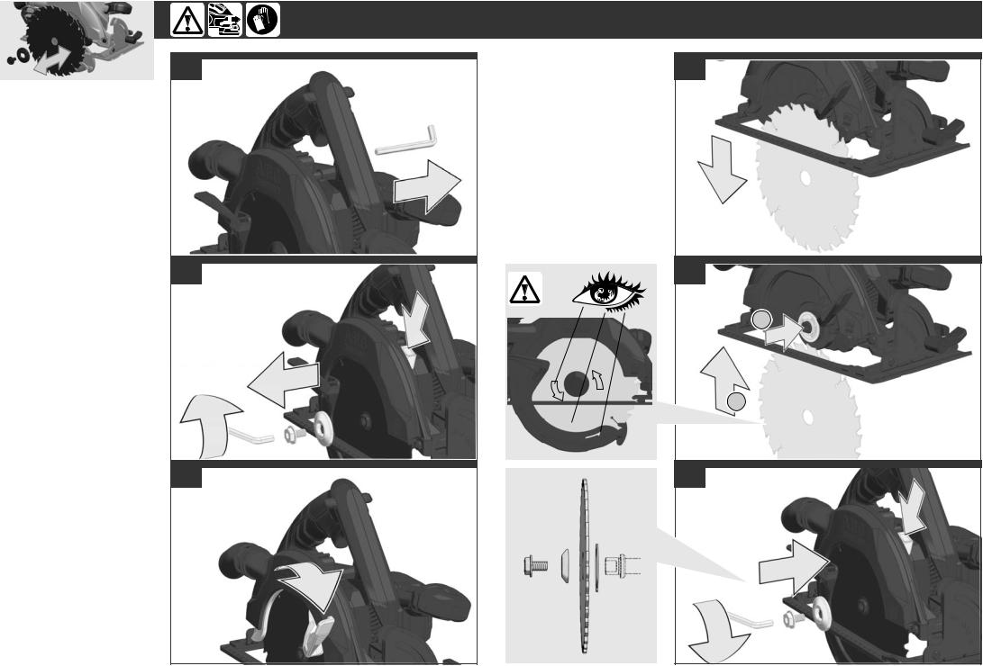
Adjust the cutting depth to the thickness of the workpiece. Less than a full tooth of the blade teeth should be visible below the workpiece.
Passen Sie die Schnitttiefe an die Dicke des Werkstücks an. Es sollte weniger als eine volle Zahnhöhe unter dem Werkstück sichtbar sein.
Adapter la profondeur de coupe à l’épaisseur de la pièce. Moins d’une dent complète devrait apparaître sous la pièce.
Adattare la profondità di taglio allo spessore del pezzo in lavorazione. Nella parte inferiore del pezzo in lavorazione dovrebbe essere visibile meno della completa altezza del dente.
Adaptar la profundidad de corte al grosor de la pieza de trabajo. La hoja de sierra no deberá sobresalir más de un diente de la pieza de trabajo.
Adaptar a profundidade de corte à espessura da peça a ser trabalhada. Deveria estar visível por aproximadamente menos do que uma altura de dente abaixo da peça a ser trabalhada.
Pas de zaagdiepte aan de dikte van het werkstuk aan. Er dient minder dan een volledige tandhoogte onder het werkstuk zichtbaar te zijn.
Tilpas skæredybden efter arbejdsemnets tykkelse. Der må maksimalt være en hel tandhøjde synlig under emnet.
Tilpass skjæredybden til tykkelsen på arbeidsstykket. Det skal være mindre enn en full tannhøyde synlig under arbeidsstykket.
Anpassa sågdjupet till arbetsstyckets tjocklek. Den synliga delen av en tand under arbetsstycket måste vara mindre än en hel tand.
Aseta leikkaussyvyys työkappaleen paksuuden mukaan. Työkappaleen alla tulisi terää näkyä korkeintaan täysi hammaskorkeus.
Προσαρμόστε το βάθος κοπής στο πάχος του υπό κατεργασία τεμαχίου. Κάτω το υπό κατεργασία τεμάχιο πρέπει να φαίνεται λιγότερο από ένα ολόκληρο δόντι του πριονόδισκου.
Kesme derinliğini iş parçasının kalınlığına göre ayarlayın. İş parçası altında tam diş uzunluğunun daha azı görünmelidir.
Přizpůsobte hloubku řezu tloušťce obrobku. Pod obrobkem by měla být viditelná méně než celá výška zubu.
Hrúbku rezu prispôsobte hrúbke obrobka. Pod obrobkom by malo byť vidieť menej pílového listu ako plnú výšku zuba píly.
Głębokość cięcia należy dopasować do grubości obrabianego przedmiotu. Powinno być widoczne mniej jak pełna wysokość zębów pod obrabianym przedmioten.
A vágási mélységet a munkadarab vastagságának megfelelően kell megválasztani. A fűrészlapból a munkadarab alatt kevesebb mind egy teljes fogmagasságnyinak kell kilátszania.
Prosimo, da globino reza prilagodite debelini obdelovanca. Znaša naj manj kot višina zoba, ki je vidna pod obdelovancem.
Prilagodite dubinu rezanja debljini izratka. Ispod izratka treba biti vidljiv manje od jedan puni zub.
Izvçlieties zâìçðanas dziïumu, kas atbilst zâìçjamâ priekðmeta biezumam. Zâìçðanas dziïumam jâbût tik lielam, lai zem zâìçjamâ priekðmeta redzamâs asmens daïas augstums bûtu mazâks par asmens zobu augstumu.
Pjovimo gylá tinkamai nustatykite pagal ruoðinio storá. Ruoðinio apaèioje turi matytis ðiek tiek maþiau, nei per visà pjûklo danties aukðtá, iðlindusi disko dalis.
Kohandage lõikesügavus tooriku paksusega. Saeketas võib tooriku alt vähem kui ühe täishamba võrra välja ulatuda.
Устанавливайте глубину реза в соответствии с толщиной детали. Под деталью пильное полотно не должно высовываться более чем на один зуб.
Винаги настройвайте дълбочината на рязане съобразно дебелината на стената на обработвания детайл. От обратната страна на детайла дискът трябва да се подава на разстояние, по-малко от една височина на зъба.
Adaptaţi adâncimea de tăiere la grosimea piesei de lucru. Sub piesa de lucru ar trebui să se vadă mai puţin de înălţimea întreagă a unui dinte.
Прилагодете ја длабочината на засекот во зависност од густината на обработуваното парче. Нешто помалку од цел забец од сечилото треба да биде видлив под работното парче.
Глибина різання повинна відповідати товщині заготовки. Під заготовкою пилковий диск має виступати не більше, ніж на одну повну висоту зубців.
ﺍﺽﺏﻁ ﻉﻡﻕ ﺍﻝﻕﻁﻉ ﻭﻑﻕًﺍ ﻝﺱُﻡﻙ ﻕﻁﻉﺓ ﺍﻝﻉﻡﻝ. ﻱﺝﺏ ﺃﻥ ﺕﻅﻩﺭ ﺍﻝﺃﺱﻥﺍﻥ ﺃﻕﻝ ﻡﻥ ﻙﺍﻡﻝ ﻁﻭﻝﻩﺍ ﺕﺡﺕ ﻕﻁﻉﺓ ﺍﻝﻉﻡﻝ.
 11
11
START
STOP
1
2
For safety reasons this power tool is fi tted with a switch lock and the On-/Off switch cannot be locked in the "On" position.
Aus Sicherheitsgründen ist das Elektrowerkzeug mit einer Einschaltsperre versehen und der Ein-/Ausschalter läßt sich nicht arretieren.
Pour des raisons de sécurité, l'outil électrique est doté d'un verrouillage de mise en marche et le commutateur de mise en marche et d'arrêt ne peut pas s'enclencher.
Per motivi di sicurezza, questo utensile elettrico é dotato di pulsante d'arresto.
Por razones de seguridad la herramienta electtricatiente un seguro de arranque, el interruptor de arranque no tiene la posibilidad de de enclaviemento.
Por razões de segurança a ferramenta eléctrica possui um encravamento de ligação. Além disso, não é possível fi xar o interruptor.
Uit veiligheidsoverwegingen is de machine van een inschakelvergrendeling voorzien en de aan-uitschakelaar is niet te vergrendelen.
Maskinen er af sikkerhedshensysn forsysnet med en indkoblingsspærre.
Av sikkerhetsgrunner er elektroverktøyet utstyrt med innkoblingssperre, og av-/på-bryteren lar seg ikke låse.
För Din säkerhet är maskinen utrustad med låsknapp så strömbrytaren ej kan tryckas in.
Turvallisuussyistä on ko. sähkötyökalu varustettu kytkemisen estolla ja On-Ei-kytkintä ei voi lukita.
Фп злекфсйкь есгблеЯп еЯнбй еопрлйумЭнп гйб льгпхт буцблеЯбт ме мЯб буцЬлейб енесгпрпЯзузт кбй п дйбкьрфзт енесгпрпЯзузт/бренесгпрпЯзузт ден мрпсеЯ нб буцблйуфеЯ.
Güvenlik nedenleriyle bu alet bir kapama emniyeti ile donatılmış olup, açma/kapama şalteri kilitlenmez.
Z bezpečnostních důvodů nelze zaaretovat vypínač v poloze ZAPNUTO.
Z bezpečnostých dôvodov je toto elektrické náradie vybavené blokovacím zariadením spúšťania a aretácia vypínača nie je možná.
Ze względów bezpieczeństwa to elektronarzędzie jest wyposażone w blokadę wyłącznika, a wyłącznika On/Off nie można zablokować w pozycji On (WŁ).
Biztonsági okokból ez a szerszám egy olyan KI/BE kapcsolóval van szerelve, ami nem rögzíthető “BE” állásban.
Iz varnostnih razlogov je električno orodje opremljeno z zaporo vklopa in stikalo za vklop/izklop se ne da kiksirati.
Iz sigurnosnih razloga električni alat je predviđen jednim zatvaračem za uključivanje i prekidač za uključivanje i isključivanje se ne može aretirati.
Drošības nolūkā elektriskie instrumenti ir aprīkoti ar slēdža bloķētāju un slēdzi nevar nofi ksēt.
Saugumo sumetimais elektros prietaise yra paleidimo blokavimo mechanizmas, ir negalima užfi ksuoti įjungimo/ išjungimo jungiklio.
Turvakaalutlustel on elektritööriist varustatud sisselülitusblokeeringuga ning sisse-välja lülitit pole võimalik fi kseerida.
Из соображений безопасности этот электроинструмент оснащенен блокиратором включения, который служит для предотвращения самопроизвольного или случайного включения.
От съображения за безопасност електрическият инструмент има блокировка на включването и бутонът за включване и изключване не може да се блокира.
Din motive de securitate aceasta scula electrică este dotată cu un blocaj pe comutator iar comutatorul Pornire / Oprire nu poate fi blocat în poziţia „Pornit“
Од безбедносни причини оваа машина е обезбедена со прекинувач кочница така што прекинувачот за вклучување не може да се заклучи во вклучена позиција.
Для цілей безпеки електроінструмент обладнаний механізмом блокування проти включення; вмикач/вимикач неможливо заблокувати.
ﺡﺎﺗﻣ ﻝﻔﻗ ﻥﻛﻣﻳ ﻻ ﺎﻣﻛ ﻝﻔﻗ ﺡﺎﺗﻔﻣﺑ ﺔﻳﺑﺭﻬﻛﻟﺍ ﺓﺍﺩﻷﺍ ﻩﺫﻫ ﺩﻳﻭﺯﺗ ﻡﺗ ﺔﻣﻼﺳﻟﺎﺑ ﻖﻠﻌﺗﺗ ﺏﺎﺑﺳﻷ ﻝﻳﻐﺷﺗ" ﻊﺿﻭﻟﺍ ﻲﻓ ﻑﺎﻘﻳﻹﺍ/ﻝﻳﻐﺷﺗﻟﺍ".
12 
 13
13
1
2
0° ... 56°
3
14 
 15
15
Carry out a test cut Probeschnitt durchführen Effectuer une coupe d‘essai Effettuare un taglio di prova Efectuar corte de prueba Efectuar experiências de corte Proefsnede maken Foretages et prøvesnit Foreta prøvekutt
Gör ett provsnitt!
РсбгмбфпрпйЮуфе мЯб дпкймбуфйкЮ фпмЮ
Deneme kesmesi yapın Proveďte zkušební řez. Vykonať skušobný rez. Wykonac próbę cięcia Végezzen teszvágást Opravite preizkusni rez! Izvesti probno rezanje
Jāveic izmēģinājuma griezums! Atlikite bandomąjį pjūvį!
Teha proovilõige!
Выполните пробный проход Направете пробно рязане! Efectuaţi un test de tăiere
Да се направи пробно сечење Виконати пробне різання
ﺇﺝﺭﺍء ﺍﺥﺕﺏﺍﺭ ﺍﻝﻕﻁﻉ
0° 45°
x cm
16
1
2
3
Accessory
Zubehör
Accessoire
Accessorio
Accessorio
Acessório
Toebehoren
Tilbehør
Tilbehør
Tillbehör
Lisälaite
ЕобсфЮмбфб
Aksesuar
Příslušenství
Príslušenstvo
Element wyposażenia dodatkowego Tartozék
Oprema
Pribor
Papildus aprīkojums Priedas
Tarvikud
Дополнитель
Аксесоар
Accesorii
Комплектуючі
ﺍﻝﻡﻝﺡﻕ
1
2
3
21
4
17
1
2
0°
3
4
18
If a correction of the 90° angle of the guide-plate to the saw blade is necessary, use the correction screw.
Falls eine Korrektur des 90° Winkels der Führungsplatte zum Sägeblatt nötig ist, diese mit der Korrekturschraube durchführen
Si une correction de l'angle à 90° de la plaque de base par rapport à la lame de scie s'avère nécessaire, il convient alors d'avoir recours à la vis de correction.
Nella caso in cui si rendesse necessaria una correzione dell 'angolo di 90° della piastra di base rispetto alla lama, questa potrà essere effettuata agendo sulla vite di correzione.
Si es necesario un ajuste o corrección de perpendicularidad (90°) del disco de sierra actuar sobre el tornillo de ajuste.
Caso se torne necessário corrigir a esquadria da base em relação ao disco de corte, agir sobre o parafuso de afi nação.
Indien een korrektie van de 90° hoek van de bodemplaat ten opzichte van het zaagblad nodig is kan deze worden gekorrigeerd met de korrektieschroef.
Såfremt det er nødvendigt med en korrektion af bundpladens 90° vinkel i forhold til savklingen, gennemføres denne med korrektionsskruen.
Hvis det er nødvendig å foreta en justering av 90°-vinkelen på føringsplaten i forhold til sagbladet, må dette gjøres med justeringsskruen.
Med ställskruv är det möjligt att justera 90°- vinkeln, bottenplatta till sågklingan.
Mikäli pohjalevyn 90°-kulman oikaisu sahanterään nähden on tarpeen, oikaisu suoritetaan oikaisuruuvista.
Уе ресЯрфщуз рпх еЯнбй брбсбЯфзфз мЯб дйьсищуз фзт гщнЯбт фщн 90° фзт рлЬкбт пдЮгзузт рспт фп дЯукп рсйпнЯумбфпт, фьфе рсЭрей бхфЮ нб рсбгмбфпрпйзиеЯ ме фпн кпчлЯб дйьсищузт
Kılavuz levhanın testere bıçağına 90°'lik konumunda bir düzeltme gerekiyorsa, bunu düzeltme vidası ile yapın.
Je-li nutná oprava kolmosti vodicí desky k pilovému kotouči, proveďte to nastavovacím šroubem.
Ak je potrebná korektúra 90° uhlu vodiacej platne k pílovému listu, použite korekčnú skrutku.
Jeżeli konieczne jest skorygowanie kąta ustawienia płytki prowadzącej 90° w stosunku do brzeszczota, należy wykorzystać do tego celu śrubę regulacyjną.
Ha az alaplap és a fűrészlap által bezárt 90 fokos szög korrekcióra szorul, használja az állító csavart.
Če je potrebna korektura 90° kota vodilne plošče k žaginemu listu, to opravite s pomočjo korekturnega vijaka.
Ako je potrebno korektura kuta vodeće ploče od 90° prema listu pile, ovu izvesti sa vijkom za korekturu.
Gadījumā, ja nepieciešama atbalsta plāksnes 90° leņķa korekcija attiecībā pret zāģa ripu, izmantojiet korekcijas skrūvi.
Jei tarp kreipiamosios ir pjūklo reikalinga 90° laipsnių pataisa, tai atlikite pataisos varžtu.
Juhul kui on vaja parandada juhtplaadi 90° nurka saelehe suhtes, siis tehke seda korrigeeriva kruviga.
Для регулировки угла 90 град направляющей шины пильного полотна служит регулировочный винт
Ако е необходима корекция на ъгъла от 90° на водещата плоча спрямо режещия диск, направете я с коригиращия винт.
Dacă este necesară o corecţie în unghi de 90° a plăcii de ghidare faţă de lama ferăstraului, utilizaţi şurubul de corecţie.
Доколку е потребно корегирање на аголот од 90° водечката површина кон сечилото на пилата, користет го шрафот за корекција.
Якщо необхідна корекція кута 90° напрямної пластини пилкового диску, виконати корекцію за допомоги регулювального гвинта
ﺇﺫﺍ ﺕﻁﻝﺏ ﺍﻝﺃﻡﺭ ﺕﺹﺡﻱﺡ ﺍﻝﺯﺍﻭﻱﺓ ﺍﻝﻕﺍﺉﻡﺓ ﻝﻝﻭﺡﺓ ﺍﻝﺕﻭﺝﻱﻩ ﺍﻝﺥﺍﺹﺓ ﺏﺵﻑﺭﺓ ﺍﻝﻡﻥﺵﺍﺭ، ﺍﺱﺕﺥﺩﻡ ﺏﺭﻍﻱ ﺍﻝﺕﺹﺡﻱﺡ ﻝﻝﻕﻱﺍﻡ ﺏﺫﻝﻙ.
90°
19
|
|
|
|
|
|
|
|
|
|
|
|
|
|
|
|
|
|
|
|
|
|
|
|
|
|
|
|
|
|
|
|
|
|
|
|
|
|
|
1 |
|
1 |
||||||
|
|
|
|
|
|
|
|
|
|
||
|
|
|
|
|
|
|
|
|
|
|
|
|
|
|
|
|
|
|
|
|
|
|
|
2
|
|
|
|
|
|
|
|
|
|
|
|
|
|
|
|
|
|
|
|
|
2 |
|
3 |
0°  45°
45°
4
1
START
2
1 STOP
2
20 
 21
21

1
2
3
4
22
0°
1
START
2
max 64 mm
23

24 
 25
25
TECHNICAL DATA |
CORDLESS CIRCULAR SAW |
BKS 18BL |
Production code...................................................................... |
..................... |
4568 70 01... |
No-load speed |
|
...000001-999999 |
....................... |
3800 min-1 |
|
Base plate dimensions (LxW)................................................. |
.................. |
298x160 mm |
Saw blade diameter................................................................ |
......................... |
190 mm |
Sawblade thickness / setting max. ......................................... .......................... |
1,1 mm |
|
Tooth thickness / setting max. |
................................................ .......................... |
1,7 mm |
Tooth thickness / setting min. ................................................. |
.......................... |
1,5 mm |
Sawblade mounting bore ....................................................... |
........................... |
30 mm |
Cutting depth at 90°................................................................ |
........................... |
64 mm |
Cutting depth at 45°................................................................ |
........................... |
46 mm |
Battery voltage........................................................................ |
........................... |
18 V |
Weight according EPTA-Procedure 01/2003 (1.5 Ah) ............ .......................... |
3,7 kg |
|
Weight according EPTA-Procedure 01/2003 (2.0 Ah) ............ .......................... |
3,7 kg |
|
Weight according EPTA-Procedure 01/2003 (3.0 Ah) ............ .......................... |
3,9 kg |
|
Weight according EPTA-Procedure 01/2003 (4.0 Ah) ............ .......................... |
3,9 kg |
|
Weight according EPTA-Procedure 01/2003 (5.0 Ah) ............ ........................ |
3,95 kg |
|
Weight according EPTA-Procedure 01/2003 (6.0 Ah) ............ .......................... |
4,1 kg |
|
Noise/vibration information |
|
|
Measured values determined according to EN 60 745. |
|
|
Typically, the A-weighted noise levels of the tool are: |
80 dB (A) |
|
Sound power level (Uncertainty K=3dB(A))......................... ........................... |
||
Sound pressure level (Uncertainty K=3dB(A))..................... ........................... |
91 dB (A) |
|
Wear ear protectors! |
|
|
Total vibration values (vector sum in the three axes) |
|
|
determined according to EN 60745. |
|
|
Vibration emission value ah |
|
< 2,5 m/s2 |
Cutting wood........................................................................ |
....................... |
|
Uncertainty K....................................................................... |
.......................... |
1,5 m/s2 |
WARNING
The vibration emission level given in this information sheet has been measured in accordance with a standardised test given in EN 60745 and may be used to compare one tool with another. It may be used for a preliminary assessment of exposure.
The declared vibration emission level represents the main applications of the tool. However if the tool is used for different applications, with different accessories or poorly maintained, the vibration emission may differ. This may signifi cantly increase the exposure level over the total working period.
An estimation of the level of exposure to vibration should also take into account the times when the tool is switched off or when it is running but not actually doing the job. This may signifi cantly reduce the exposure level over the total working period.
Identify additional safety measures to protect the operator from the effects of vibration such as: maintain the tool and the accessories, keep the hands warm, organisation of work patterns.
 WARNING! Read all safety warnings and all instructions. Failure to follow the warnings and instructions may result in electric shock, fi re and/or serious injury.
Save all warnings and instructions for future reference. 
 CIRCULAR SAW SAFETY WARNINGS
Cutting procederes
 Danger: Keep hands away from cutting area and the blade. Keep your second hand on auxiliary handle, or motor housing. If both hands are holding the saw, they cannot be cut by the blade.
Do not reach underneath the workpiece. The guard cannot protect you from the blade below the workpiece.
Adjust the cutting depth to the thickness of the workpiece. Less than a full tooth of the blade teeth should be visible below the workpiece.
Never hold piece being cut in your hands or across your leg. Secure the workpiece to a stable platform. It is important to support the work properly to minimize body exposure, blade binding, or loss of control.
Hold the power tool by insulated gripping surfaces, only when performing an operation where the cutting tool may contact hidden wiring. Cutting accessory contacting a „live“ wire may make exposed metal parts of the power tool „live“ and could give the operator an electric shock.
When ripping always use a rip fence or straight edge guide. This improves the accuracy of cut and reduces the chance of blade binding.
Always use blades with correct size and shape (diamond versus round) of arbour holes. Blades that do not match the mounting hardware of the saw will run eccentrically, causing loss of control.
Never use damaged or incorrect blade washers or bolt.
The blade washers and bolt were specially designed for your saw, for optimum performance and safety of operation.
Kickback causes and related warnings:
-kickback is a sudden reaction to a pinched, bound or misaligned saw blade, causing an uncontrolled saw to lift up and out of the workpiece toward the operator;
-when the blade is pinched or bound tightly by the kerf closing down, the blade stalls and the motor reaction drives the unit rapidly back toward the operator;
-if the blade becomes twisted or misaligned in the cut, the teeth at the back edge of the blade can dig into the top surface of the wood causing the blade to climb out of the kerf and jump back toward the operator.
Kickback is the result of saw misuse and/or incorrect operating procedures or conditions and can be avoided by taking proper precautions as given below.
Maintain a firm grip with both hands on the saw and position your arms to resist kickback forces. Position your body to either side of the blade, but not in line with the blade. Kickback could cause the saw to jump backwards, but kickback forces can be controlled by the operator, if proper precautions are taken.
When blade is binding, or when interrupting a cut for any reason, release the trigger and hold the saw
motionless in the material until the blade comes to a complete stop. Never attempt to remove the saw from the work or pull the saw backward while the blade is in motion or kickback may occur. Investigate and take corrective actions to eliminate the cause of blade binding.
When restarting a saw in the workpiece, centre the saw blade in the kerf and check that saw teeth are not engaged into the material. If saw blade is binding, it may walk up or kickback from the workpiece as the saw is restarted.
Support large panels to minimise the risk of blade pinching and kickback. Large panels tend to sag under their own weight. Supports must be placed under the panel on both sides, near the line of cut and near the edge of the panel.
Do not use dull or damaged blades. Unsharpened or improperly set blades produce narrow kerf causing excessive friction, blade binding and kickback.
Blade depth and bevel adjusting locking levers must be tight and secure before making cut. If blade adjustment shifts while cutting, it may cause binding and kickback.
Use extra caution when sawing into existing walls or other blind areas. The protruding blade may cut objects that can cause kickback.
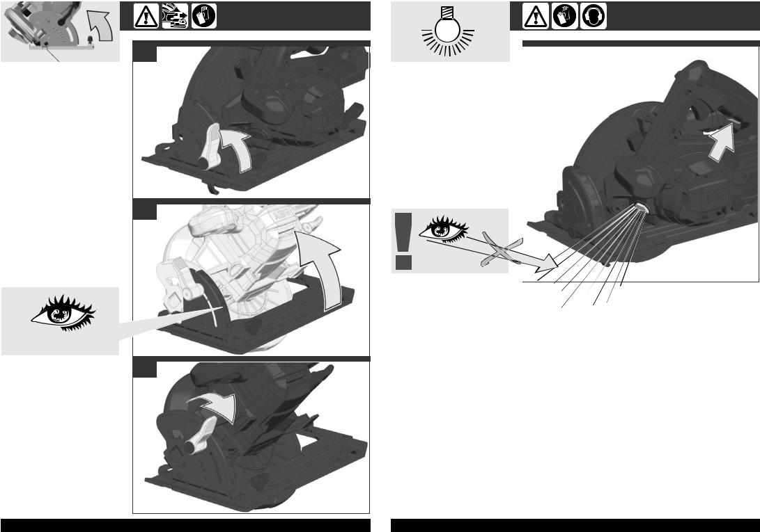
Lower guard function
Check lower guard for proper closing before each use. Do not operate the saw if lower guard does not move freely and close instantly. Never clamp or tie the lower guard into the open position. If saw is accidentally dropped, lower guard may be bent. Raise the lower guard with the retracting handle and make sure it moves freely and does not touch the blade or any other part, in all angles and depths of cut.
Check the operation of the lower guard spring. If the guard and the spring are not operating properly, they must be serviced before use. Lower guard may operate sluggishly due to damaged parts, gummy deposits, or a build-up of debris.
Lower guard may be retracted manually only for special cuts such as “plunge cuts” and “compound cuts.” Raise lower guard by retracting handle and as soon as blade enters the material, the lower guard must be released. For all other sawing, the lower guard should operate automatically.
Always observe that the lower guard is covering the blade before placing saw down on bench or floor. An unprotected, coasting blade will cause the saw to walk backwards, cutting whatever is in its path. Be aware of the time it takes for the blade to stop after switch is released.
ADDITIONAL SAFETY AND WORKING INSTRUCTIONS
Do not use saw blades not corresponding to the key data given in these instructions for use.
The dust produced when using this tool may be harmful to health. Do not inhale the dust. Wear a suitable dust protection mask.
Wear ear protectors. Exposure to noise can cause hearing loss.
Please do not use abrasion disks in this machine!
Remove the battery pack before starting any work on the machine.
Do not dispose of used battery packs in the household refuse or by burning them. AEG Distributors offer to retrieve old batteries to protect our environment.
Do not store the battery pack together with metal objects (short circuit risk).
Use only System GBS chargers for charging System GBS battery packs. Do not use battery packs from other systems.
Never break open battery packs and chargers and store only in dry rooms. Keep dry at all times.
Battery acid may leak from damaged batteries under extreme load or extreme temperatures. In case of contact with battery acid wash it off immediately with soap and water. In case of eye contact rinse thoroughly for at least 10 minutes and immediately seek medical attention.
Adapt the feed speed to avoid overheating the blade tips.
SPECIFIED CONDITIONS OF USE
This cordless circular saw is intended to be used to cut lengthways and mitre accurately in wood.
Do not use this product in any other way as stated for normal use.
EC-DECLARATION OF CONFORMITY
We declare under our sole responsibility that the product described under “Technical Data” fulfi lls all the relevant provisions of the directives 2011/65/EU (RoHs), 2014/30/ EU, 2006/42/EC and the following harmonized standards have been used:
EN 60745-1:2009 + A11:2010 EN 60745-2-5:2010
EN 55014-1:2006 + A1:2009 + A2:2011
EN 55014-2:1997 + A1:2001 + A2:2008 EN 50581:2012
Winnenden, 2016-03-29
Alexander Krug
Managing Director
Authorized to compile the technical fi le.
Techtronic Industries GmbH Max-Eyth-Straße 10 71364 Winnenden Germany
BATTERIES
Battery packs which have not been used for some time should be recharged before use.
Temperatures in excess of 50°C (122°F) reduce the performance of the battery pack. Avoid extended exposure to heat or sunshine (risk of overheating).
The contacts of chargers and battery packs must be kept clean.
For an optimum life-time, the battery packs have to be fully charged, after used.
To obtain the longest possible battery life remove the battery pack from the charger once it is fully charged.
For battery pack storage longer than 30 days:
Store the battery pack where the temperature is below 27°C and away from moisture
Store the battery packs in a 30% - 50% charged condition Every six months of storage, charge the pack as normal.
BATTERY PACK PROTECTION LI-ION BATTERY
The battery pack has overload protection that protects it from being overloaded and helps to ensure long life. Under extreme stress the battery electronics switch off the machine automatically. To restart, switch the machine off and then on again. If the machine does not start up again, the battery pack may have discharged completely. In this case it must be recharged in the battery charger.
TRANSPORTING LITHIUM BATTERIES
Lithium-ion batteries are subject to the Dangerous Goods Legislation requirements.
Transportation of those batteries has to be done in accordance with local, national and international provisions and regulations.
•The user can transport the batteries by road without further requirements.
26 |
ENGLISH |
|
ENGLISH |
27 |
•Commercial transport of Lithium-Ion batteries by third parties is subject to Dangerous Goods regulations. Transport preparation and transport are exclusively to be carried out by appropriately trained persons and the process has to be accompanied by corresponding experts.
When transporting batteries:
•Ensure that battery contact terminals are protected and insulated to prevent short circuit.
•Ensure that battery pack is secured against movement within packaging.
•Do not transport batteries that are cracked or leak.
Check with forwarding company for further advice
MAINTENANCE
The ventilation slots of the machine must be kept clear at all times.
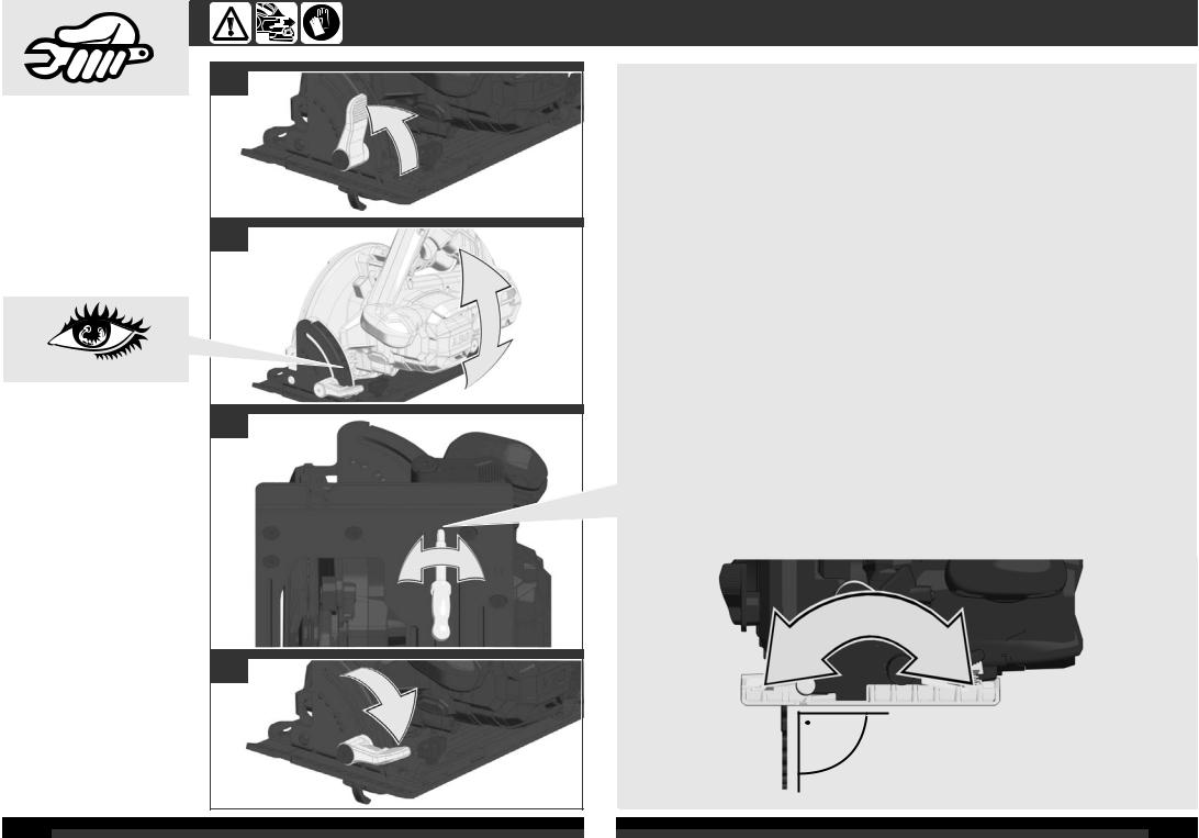
Be sure to disconnect the tool from the power supply before attaching or removing the saw blade.
Clean tool and guarding system with dry cloth. Certain cleaning agents and solvents are harmful to plastics and other insulated parts. Keep the apparatus handle clean, dry and free of spilt oil or grease. Check the function of guards. Regular maintenance and cleaning provide for a long service life and safe handling.
Use only AEG accessories and AEG spare parts. Should components need to be replaced which have not been described, please contact one of our AEG service agents (see our list of guarantee/service addresses).
If needed, an exploded view of the tool can be ordered. Please state the machine type printed as well as the six-digit No. on the label and order the drawing at your local service agents or directly at: Techtronic Industries GmbH, Max-Eyth-Straße 10, 71364 Winnenden, Germany.
SYMBOLS
CAUTION! WARNING! DANGER!
Remove the battery pack before starting any work on the machine.
Please read the instructions carefully before starting the machine.
Wear gloves!
Wear ear protectors!
Always wear goggles when using the machine.
Accessory - Not included in standard equipment, available as an accessory.
Do not dispose of electric tools together with household waste material.
Electric tools and electronic equipment that have reached the end of their life must be collected separately and returned to an environmentally compatible recycling facility.
Check with your local authority or retailer for recycling advice and collection point.

 European Conformity Mark
National mark of conformity Ukraine
EurAsian Conformity Mark.
TECHNISCHE DATEN |
AKKU-KREISSÄGE |
BKS 18BL |
...............................................................Produktionsnummer |
..................... |
4568 70 01... |
Leerlaufdrehzahl |
|
...000001-999999 |
....................... |
3800 min-1 |
|
Bodenplatte Größe (LxB).............................................................. |
.................. |
298x160 mm |
Sägeblattdurchmesser.................................................................. |
......................... |
190 mm |
Sägeblattdicke / Schränkung, max............................................... |
.......................... |
1,1 mm |
Sägezahndicke / Schränkung, max.............................................. |
.......................... |
1,7 mm |
Sägezahndicke / Schränkung, min............................................... |
.......................... |
1,5 mm |
Sägeblatt Bohrungsdurchmesser................................................. |
........................... |
30 mm |
Schnitttiefe bei 90°......................................................................... |
........................... |
64 mm |
Schnitttiefe bei 45°......................................................................... |
........................... |
46 mm |
Spannung Wechselakku .............................................................. |
........................... |
18 V |
Gewicht nach EPTA-Prozedur 01/2003 (1,5Ah).......................... .......................... |
3,7 kg |
|
Gewicht nach EPTA-Prozedur 01/2003 (2,0Ah).......................... .......................... |
3,7 kg |
|
Gewicht nach EPTA-Prozedur 01/2003 (3,0Ah).......................... .......................... |
3,9 kg |
|
Gewicht nach EPTA-Prozedur 01/2003 (4,0Ah).......................... .......................... |
3,9 kg |
|
Gewicht nach EPTA-Prozedur 01/2003 (5,0Ah).......................... ........................ |
3,95 kg |
|
Gewicht nach EPTA-Prozedur 01/2003 (6,0Ah).......................... .......................... |
4,1 kg |
|
Geräusch/Vibrationsinformation |
|
|
Messwerte ermittelt entsprechend EN 60 745. |
|
|
DerA-bewertete Geräuschpegel des Gerätes beträgt typischerweise: |
80 dB (A) |
|
Schalldruckpegel (Unsicherheit K=3dB(A))................................ ........................... |
||
Schallleistungspegel (Unsicherheit K=3dB(A))........................... ........................... |
91 dB (A) |
|
Gehörschutz tragen! |
|
|
Schwingungsgesamtwerte (Vektorsumme dreier Richtungen) |
|
|
ermittelt entsprechend EN 60745. |
|
|
Schwingungsemissionswert ah |
|
< 2,5 m/s2 |
Sägen von Holz.......................................................................... |
....................... |
|
Unsicherheit K =......................................................................... |
.......................... |
1,5 m/s2 |
WARNUNG
Der in diesenAnweisungen angegebene Schwingungspegel ist entsprechend einem in EN 60745 genormten Messverfahren gemessen worden und kann für den Vergleich von Elektrowerkzeugen miteinander verwendet werden. Er eignet sich auch für eine vorläufige Einschätzung der Schwingungsbelastung.
Der angegebene Schwingungspegel repräsentiert die hauptsächlichenAnwendungen des Elektrowerkzeugs. Wenn allerdings das Elektrowerkzeug für andereAnwendungen, mit abweichenden Einsatzwerkzeugen oder ungenügender Wartung eingesetzt wird, kann der Schwingungspegel abweichen. Dies kann die Schwingungsbelastung über den gesamtenArbeitszeitraum deutlich erhöhen.
Für eine genaueAbschätzung der Schwingungsbelastung sollten auch die Zeiten berücksichtigt werden, in denen das Gerät abgeschaltet ist oder zwar läuft, aber nicht tatsächlich im Einsatz ist. Dies kann die Schwingungsbelastung über den gesamten Arbeitszeitraum deutlich reduzieren.
Legen Sie zusätzliche Sicherheitsmaßnahmen zum Schutz des Bedieners vor der Wirkung von Schwingungen fest wie zum Beispiel: Wartung von Elektrowerkzeug und Einsatzwerkzeugen, Warmhalten der Hände, Organisation derArbeitsabläufe.
 WARNUNG! Lesen Sie alle Sicherheitshinweise und Anweisungen. Versäumnisse bei der Einhaltung der Sicherheitshinweise und Anweisungen können elektrischen Schlag, Brand und/oder schwere Verletzungen verursachen.
Bewahren Sie alle Sicherheitshinweise und Anweisungen für die Zukunft auf.

 SICHERHEITSHINWEISE FÜR KREISSÄGEN
Sägeverfahren
 Gefahr: Kommen Sie mit Ihren Händen nicht in den Sägebereich und an das Sägeblatt. Halten Sie mit Ihrer zweiten Hand den Zusatzgriff oder das Motorgehäuse.
Wenn beide Hände die Kreissäge halten, kann das Sägeblatt diese nicht verletzen.
Greifen Sie nicht unter das Werkstück. Die Schutzhaube kann Sie unter dem Werkstück nicht vor dem Sägeblatt schützen.
Passen Sie die Schnitttiefe an die Dicke des Werkstücks an. Es sollte weniger als eine volle Zahnhöhe unter dem Werkstück sichtbar sein.
Halten Sie das zu sägende Werkstück niemals in der Hand oder über dem Bein fest. Sichern Sie das Werkstück an einer stabilen Unterlage. Es ist wichtig, das Werkstück gut zu befestigen, um die Gefahr von Körperkontakt, Klemmen des Sägeblattes oder Verlust der Kontrolle zu minimieren.
Fassen Sie das Elektrowerkzeug an den isolierten Griffflächen an, wenn Sie Arbeiten ausführen, bei denen das Einsatzwerkzeug verborgene Stromleitungen treffen kann.
Kontakt mit einer spannungsführenden Leitung setzt auch die Metallteile des Elektrowerkzeugs unter Spannung und führt zu einem
elektrischen Schlag.
Verwenden Sie beim Längsschneiden immer einen Anschlag oder eine gerade Kantenführung. Dies verbessert die Schnittgenauigkeit und verringert die Möglichkeit, dass das Sägeblatt klemmt.
Verwenden Sie immer Sägeblätter in der richtigen Größe und mit passender Aufnahmebohrung (z.B. sternförmig oder rund). Sägeblätter, die nicht zu den Montageteilen der Säge passen, laufen unrund und führen zum Verlust der Kontrolle.
Verwenden Sie niemals beschädigte oder falsche Sägeblatt-Unterlegscheiben oder -schrauben. Die Sägeblatt-Unterlegscheiben und -schrauben wurden speziell für Ihre Säge konstruiert, für optimale Leistung und Betriebssicherheit.
Ursachen und Vermeidung eines Rückschlags:
–ein Rückschlag ist die plötzliche Reaktion infolge eines hakenden, klemmenden oder falsch ausgerichteten Sägeblattes, die dazu führt, dass eine unkontrollierte Säge abhebt und sich aus dem Werkstück heraus in Richtung der Bedienperson bewegt;
–wenn sich das Sägeblatt in dem sich schließenden Sägespalt verhakt oder verklemmt, blockiert es, und die Motorkraft schlägt das Gerät in Richtung der Bedienperson zurück;
28 |
ENGLISH |
|
DEUTSCH |
29 |
– wird das Sägeblatt im Sägeschnitt verdreht oder falsch ausgerichtet, können sich die Zähne der hinteren Sägeblattkante in der Oberfläche des Werkstücks verhaken, wodurch sich das Sägeblatt aus dem Sägespalt herausbewegt und die Säge in Richtung der Bedienperson zurückspringt.
Ein Rückschlag ist die Folge eines falschen oder fehlerhaften Gebrauchs der Säge. Er kann durch geeignete Vorsichtsmaßnahmen, wie nachfolgend beschrieben, verhindert werden.
Halten Sie die Säge mit beiden Händen fest und bringen Sie Ihre Arme in eine Stellung, in der Sie den Rückschlagkräften standhalten können. Halten Sie sich immer seitlich des Sägeblattes, nie das Sägeblatt in eine Linie mit Ihrem Körper bringen. Bei einem Rückschlag kann die Kreissäge rückwärts springen, jedoch kann die Bedienperson die Rückschlagkräfte beherrschen, wenn geeignete Maßnahmen getroffen wurden.
Falls das Sägeblatt klemmt oder das Sägen aus einem anderen Grund unterbrochen wird, lassen Sie den Ein-Aus-Schalter los und halten Sie die Säge im Werkstoff ruhig, bis das Sägeblatt vollständig stillsteht. Versuchen Sie niemals, die Säge aus dem Werkstück zu entfernen oder sie rückwärts zu ziehen, solange das Sägeblatt sich bewegt oder sich ein Rückschlag ereignen könnte. Finden Sie die Ursache für das Klemmen des Sägeblattes und beseitigen Sie diese durch geeignete Maßnahmen.
Wenn Sie eine Säge, die im Werkstück steckt, wieder starten wollen, zentrieren Sie das Sägeblatt im Sägespalt und überprüfen Sie, ob die Sägezähne nicht im Werkstück verhakt sind. Klemmt das Sägeblatt, kann es sich aus dem Werkstück heraus bewegen oder einen Rückschlag verursachen, wenn die Säge erneut gestartet wird.
Stützen Sie große Platten ab, um das Risiko eines Rückschlags durch ein klemmendes Sägeblatt zu vermindern. Große Platten können sich unter ihrem Eigengewicht durchbiegen. Platten müssen auf beiden Seiten, sowohl in Nähe des Sägespalts als auch am Rand, abgestützt werden.
Verwenden Sie keine stumpfen oder beschädigten Sägeblätter. Sägeblätter mit stumpfen oder falsch ausgerichteten Zähnen verursachen durch einen zu engen Sägespalt eine erhöhte Reibung, Klemmen des Sägeblattes und Rückschlag.
Ziehen Sie vor dem Sägen die Schnitttiefenund Schnittwinkeleinstellungen fest. Wenn sich während des Sägens die Einstellungen verändern, kann sich das Sägeblatt verklemmen und ein Rückschlag auftreten.
Seien Sie besonders vorsichtig, wenn Sie einen Schnitt in einen verborgenen Bereich, z.B. eine bestehende Wand, ausführen. Das eintauchende Sägeblatt kann beim Sägen in verborgene Objekte blockieren und einen Rückschlag verursachen.
Funktion der unteren Schutzhaube
Überprüfen Sie vor jeder Benutzung, ob die untere Schutzhaube einwandfrei schließt. Verwenden Sie die Säge nicht, wenn die untere Schutzhaube nicht frei beweglich ist und sich nicht sofort schließt. Klemmen oder binden Sie die untere Schutzhaube niemals in geöffneter Position fest. Sollte die Säge unbeabsichtigt zu Boden fallen, kann die untere Schutzhaube verbogen werden. Öffnen Sie die Schutzhaube mit dem Rückziehhebel und stellen Sie sicher, dass sie sich frei bewegt und bei allen Schnittwinkeln und -tiefen weder Sägeblatt noch andere Teile berührt.
Überprüfen Sie die Funktion der Feder für die untere Schutzhaube. Lassen Sie das Gerät vor dem Gebrauch warten, wenn untere Schutzhaube und Feder nicht einwandfrei arbeiten. Beschädigte Teile, klebrige Ablagerungen oderAnhäufungen von Spänen lassen die untere Schutzhaube verzögert arbeiten.
Öffnen Sie die untere Schutzhaube von Hand nur bei besonderen Schnitten, wie „Tauch - und Winkelschnitten“. Öffnen Sie die untere Schutzhaube mit dem Rückziehhebel und lassen Sie diesen los, sobald das
Sägeblatt in das Werkstück eingedrungen ist. Bei allen anderen Sägearbeiten muss die untere Schutzhaube automatisch arbeiten.
Legen Sie die Säge nicht auf der Werkbank oder dem Boden ab, ohne dass die untere Schutzhaube das Sägeblatt bedeckt. Ein ungeschütztes, nachlaufendes Sägeblatt bewegt die Säge entgegen der Schnittrichtung und sägt, was ihm im Weg ist. Beachten Sie dabei die Nachlaufzeit der Säge.
WEITERE SICHERHEITSUND ARBEITSHINWEISE
Sägeblätter, die nicht den Kenndaten in dieser Gebrauchsanweisung entsprechen, dürfen nicht verwendet werden.
BeimArbeiten entstehender Staub ist oft gesundheitsschädlich und sollte nicht in den Körper gelangen. Geeignete Staubschutzmaske tragen.
Tragen Sie Gehörschutz. Die Einwirkung von Lärm kann Gehörverlust bewirken.
Keine Schleifscheiben einsetzen.
Vor allenArbeiten an der Maschine den Wechselakku herausnehmen
Verbrauchte Wechselakkus nicht ins Feuer oder in den Hausmüll werfen.AEG bietet eine umweltgerechteAlt- Wechselakku-Entsorgung an; bitte fragen Sie Ihren Fachhändler.
Wechselakkus nicht zusammen mit Metallgegenständen aufbewahren (Kurzschlussgefahr).
Wechselakkus des Systems GBS nur mit Ladegeräten des Systems GBS laden. Keine Akkus aus anderen Systemen laden.
Wechselakkus und Ladegeräte nicht öffnen und nur in trockenen Räumen lagern. Vor Nässe schützen.
Unter extremer Belastung oder extremer Temperatur kann aus beschädigten Wechselakkus Batterieflüssigkeit auslaufen. Bei Berührung mit Batterieflüssigkeit sofort mit Wasser und Seife abwaschen. BeiAugenkontakt sofort mindestens 10 Minuten gründlich spülen und unverzüglich einenArzt aufsuchen.
Vermeiden Sie durch eine angepasste Vorschubgeschwindigkeit die Überhitzung der Sägeblattzähne.
BESTIMMUNGSGEMÄSSE VERWENDUNG
DieAkku-Kreissäge ist bestimmt zum Sägen von exakten Längsund Gehrungsschnitten in Holz.
Dieses Gerät darf nur wie angegeben bestimmungsgemäß verwendet werden.
CE-KONFORMITÄTSERKLÄRUNG
Wir erklären in alleiniger Verantwortung, dass das unter „Technische Daten“ beschriebene Produkt mit alle relevanten Vorschriften der Richtline 2011/65/EU (RoHs), 2014/30/EU, 2006/42/EG und den folgenden harmonisierten normativen Dokumenten übereinstimmt:
EN 60745-1:2009 + A11:2010 EN 60745-2-5:2010
EN 55014-1:2006 + A1:2009 + A2:2011
EN 55014-2:1997 + A1:2001 + A2:2008 EN 50581:2012
Winnenden, 2016-03-29
Alexander Krug
Managing Director
Bevollmächtigt die technischen Unterlagen zusammenzustellen
Techtronic Industries GmbH Max-Eyth-Straße 10 71364 Winnenden Germany
AKKUS
Längere Zeit nicht benutzte Wechselakkus vor Gebrauch nachladen.
Eine Temperatur über 50°C vermindert die Leistung des Wechselakkus. Längere Erwärmung durch Sonne oder Heizung vermeiden.
Die Anschlusskontakte an Ladegerät und Wechselakku sauber halten.
Für eine optimale Lebensdauer müssen nach dem Gebrauch die Akkus voll geladen werden.
Für eine möglichst lange Lebensdauer sollten die Akkus nach dem Aufl aden aus dem Ladegerät entfernt werden.
Bei Lagerung des Akkus länger als 30 Tage: Akku bei ca. 27°C und trocken lagern.
Akku bei ca. 30%-50% des Ladezustandes lagern. Akku alle 6 Monate erneut aufl aden.
AKKUÜBERLASTSCHUTZ LI-ION AKKU
Der Akkupack ist mit einem Überlastschutz ausgestattet, der den Akku vor Überlastung schützt und eine hohe Lebensdauer sicherstellt.
Bei extrem starker Beanspruchung schaltet die Akkuelektronik die Maschine automatisch ab. Zum Weiterarbeiten Maschine Ausund wieder Einschalten. Sollte die Maschine nicht wieder anlaufen, ist der Akkupack möglicherweise entladen und muss im Ladegerät wieder aufgeladen werden.
TRANSPORT VON LITHIUM-IONEN-AKKUS
Lithium-Ionen-Akkus fallen unter die gesetzlichen Bestimmungen zum Gefahrguttransport.
Der Transport dieser Akkus muss unter Einhaltung der lokalen, nationalen und internationalen Vorschriften und Bestimmungen erfolgen.
•Verbraucher dürfen diese Akkus ohne Weiteres auf der Straße transportieren.
•Der kommerzielle Transport von Lithium-Ionen-Akkus durch Speditionsunternehmen unterliegt den Bestimmungen des Gefahrguttransports. Die Versandvorbereitungen und der Transport dürfen ausschließlich von entsprechend geschulten Personen durchgeführt werden. Der gesamte Prozess muss fachmännisch begleitet werden.
Folgende Punkte sind beim Transport von Akkus zu beachten:
•Stellen Sie sicher, dass die Kontakte geschützt und isoliert sind, um Kurzschlüsse zu vermeiden.
•Achten Sie darauf, dass der Akkupack innerhalb der Verpackung nicht verrutschen kann.
•Beschädigte oder auslaufende Akkus dürfen nicht transportiert werden.
Wenden Sie sich für weitere Hinweise an Ihr
Speditionsunternehmen.
WARTUNG
Stets die Lüftungsschlitze der Maschine sauber halten.
Stellen Sie sicher, dass das Gerät von der Stromversorgung getrennt ist, bevor Sie das Sägeblatt anbringen oder abnehmen.
Reinigen Sie Gerät und Schutzeinrichtung mit einem trockenen Tuch. Manche Reinigungsmittel beschädigen Kunststoff oder andere isolierte Teile. Das Gerät sauber und trocken sowie frei von ausgetretenem Öl und Fett halten. Überprüfen Sie die Funktion der Schutzhauben. Regelmäßige Wartung und Reinigung sorgen für eine lange Lebensdauer und sichere Handhabung.
NurAEG Zubehör undAEG Ersatzteile verwenden. Bauteile, derenAustausch nicht beschrieben wurde, bei einerAEG Kundendienststelle auswechseln lassen (Broschüre Garantie/ Kundendienstadressen beachten).
Bei Bedarf kann eine Explosionszeichnung des Gerätes unter Angabe der Maschinen Type und der sechsstelligen
Nummer auf dem Leistungsschild bei Ihrer Kundendienststelle oder direkt bei Techtronic Industries GmbH, Max-Eyth-Straße 10, 71364 Winnenden, Germany angefordert werden.
SYMBOLE
ACHTUNG! WARNUNG! GEFAHR!
Vor allen Arbeiten an der Maschine den
Wechselakku herausnehmen
Bitte lesen Sie die Gebrauchsanweisung vor
Inbetriebnahme sorgfältig durch.
Schutzhandschuhe tragen!
Gehörschutz tragen!
Beim Arbeiten mit der Maschine stets
Schutzbrille tragen.
Zubehör - Im Lieferumfang nicht enthalten, empfohlene Ergänzung aus dem Zubehörprogramm.
Elektrogeräte dürfen nicht zusammen mit dem Hausmüll entsorgt werden.
Elektrische und elektronische Geräte sind getrennt zu sammeln und zur umweltgerechten Entsorgung bei einem Verwertungsbetrieb abzugeben.
Erkundigen Sie sich bei den örtlichen Behörden oder bei Ihrem Fachhändler nach Recyclinghöfen und Sammelstellen.

 CE-Zeichen
Nationales Konformitätszeichen Ukraine
EurAsian Konformitätszeichen
30 |
DEUTSCH |
|
DEUTSCH |
31 |

CARACTÉRISTIQUES TECHNIQUES SCIE CIRCULAIRE SANS FIL |
BKS 18BL |
..................................................................... .....................Numéro de série |
4568 70 01... |
Vitesse de rotation à vide |
...000001-999999 |
3800 min-1 |
|
Dimensions plateau base (LxP) ................................................ .................. |
298x160 mm |
Diamètre lame ........................................................................... ......................... |
190 mm |
Épaisseur lame / avoyage, max................................................. .......................... |
1,1 mm |
Épaisseur dents / avoyage, max................................................ .......................... |
1,7 mm |
Épaisseur dents / avoyage, min................................................. .......................... |
1,5 mm |
Diamètre trou montage lame .................................................... ........................... |
30 mm |
Profondeur de coupe à 90°........................................................ ........................... |
64 mm |
Profondeur de coupe à 45°........................................................ ........................... |
46 mm |
Tension accu interchangeable................................................... ........................... |
18 V |
Poids suivant EPTA-Procedure 01/2003 (1,5 Ah).................... .......................... |
3,7 kg |
Poids suivant EPTA-Procedure 01/2003 (2,0 Ah).................... .......................... |
3,7 kg |
Poids suivant EPTA-Procedure 01/2003 (3,0 Ah).................... .......................... |
3,9 kg |
Poids suivant EPTA-Procedure 01/2003 (4,0 Ah).................... .......................... |
3,9 kg |
Poids suivant EPTA-Procedure 01/2003 (5,0 Ah).................... ........................ |
3,95 kg |
Poids suivant EPTA-Procedure 01/2003 (6,0 Ah).................... .......................... |
4,1 kg |
Informations sur le bruit et les vibrations |
|
Valeurs de mesure obtenues conformément à la EN 60 745. |
|
La mesure réelle (A) du niveau de bruit de l’outil est |
80 dB (A) |
Niveau de pression acoustique (Incertitude K=3dB(A))............ ........................... |
|
Niveau d'intensité acoustique (Incertitude K=3dB(A))............... ........................... |
91 dB (A) |
Toujours porter une protection acoustique! |
|
Valeurs totales des vibrations (somme vectorielle de trois |
|
sens) établies conformément à EN 60745. |
|
Valeur d’émission vibratoire ah |
< 2,5 m/s2 |
Sciage du bois..................................................................... ....................... |
|
Incertitude K=.......................................................................... .......................... |
1,5 m/s2 |
AVERTISSEMENT
Le niveau vibratoire indiqué dans ces instructions a été mesuré selon un procédé de mesure normalisé dans la norme EN 60745 et peut être utilisé pour comparer des outils électriques entre eux. Il convient aussi à une estimation provisoire de la sollicitation par les vibrations.
Le niveau vibratoire indiqué représente les applications principales de l’outil électrique. Toutefois, si l’outil électrique est utilisé pour d’autres applications, avec des outils rapportés qui diffèrent ou une maintenance insuffi sante, il se peut que le niveau vibratoire diverge. Cela peut augmenter nettement la sollicitation par les vibrations sur tout l’intervalle de temps du travail.
Pour une estimation précise de la sollicitation par les vibrations, on devrait également tenir compte des temps pendant lesquels l’appareil n’est pas en marche ou tourne sans être réellement en service. Cela peut réduire nettement la sollicitation par les vibrations sur tout l’intervalle de temps du travail.
Défi nissez des mesures de sécurité supplémentaires pour protéger l’utilisateur contre l’infl uence des vibrations, comme par exemple : la maintenance de l’outil électrique et des outils rapportés, le maintien au chaud des mains, l’organisation des déroulements de travail.
 AVIS! Lire complètement les instructions et les indications de sécurité. Le non-respect des avertissements et instructions indiqués ci après peut entraîner un choc électrique, un incendie et/ou de graves blessures sur les personnes.
Bien garder tous les avertissements et instructions.
 CONSIGNES DE SÉCURITÉ CONCERNANT LES SCIES CIRCULAIRES
Procédures de coupe
 DANGER: Bien garder les mains à distance de la zone de sciage et de la lame de scie. Tenir la poignée supplémentaire ou le carter du moteur de l’autre main. Si vous tenez la scie circulaire des deux mains, celles-ci ne peuvent pas être blessées par la lame de scie.
Ne pas passer les mains sous la pièce à travailler. Sous la pièce à travailler, le capot de protection ne peut pas vous protéger de la lame de scie.
Adapter la profondeur de coupe à l’épaisseur de la pièce.
Moins d’une dent complète devrait apparaître sous la pièce.
Ne jamais tenir la pièce à scier dans la main ou par-dessus la jambe. Fixer la pièce sur un support stable. Il est important de bien fixer la pièce, afin de réduire au minimum les dangers causés par le contact physique, quand la lame de scie se coince ou lorsqu’on perd le contrôle.
Maintenez l’appareil par les surfaces de poignée isolées lorsque vous exécutez des travaux pendant lesquels l’outil
de coupe peut toucher des lignes électriques dissimulées.
Le contact avec un câble sous tension met les parties métalliques de l’appareil sous tension et provoque une décharge électrique.
Toujours utiliser une butée ou un guidage droit de bords pour des coupes longitudinales. Ceci améliore la précision de la coupe et réduit le danger de voir la lame de scie se coincer.
Toujours utiliser des lames de scie de la bonne taille qui ont une forme appropriée à l’alésage de fixation (par ex. en étoile ou rond). Les lames de scie qui ne conviennent pas aux parties montées de la scie sont comme voilées et entraînent une perte de contrôle.
Ne jamais utiliser de rondelles ou de vis endommagées ou qui ne conviennent pas à la lame de scie. Les rondelles et vis pour la lame de scie ont spécialement été construites pour votre scie, pour une performance et une sécurité de fonctionnement optimales.
Causes de contrecoups et comment les éviter:
–un contrecoup est une réaction soudaine d’une lame de scie qui est restée accrochée, qui s’est coincée ou qui est mal orientée qui fait que la scie incontrôlée sort de la pièce à travailler et se dirige vers la personne travaillant avec l’appareil;
–si la lame de scie reste accrochée ou se coince dans la fente sciée qui se ferme, elle se bloque et la force du moteur entraîne l’appareil vers la personne travaillant avec l’appareil;
–si la lame de scie est tordue ou mal orientée dans le tracé de la coupe, les dents du bord arrière de la lame de scie risquent de se coincer dans la surface de la pièce, ce qui fait que la lame
de scie saute brusquement de la fente et qu’elle est propulsée vers l’arrière où se trouve la personne travaillant avec l’appareil.
Un contrecoup est la suite d’une mauvaise utilisation ou une utilisation incorrecte de la scie. Il peut être évité en prenant les mesures de précaution comme elles sont décrites ci-dessous.
Bien tenir la scie des deux mains et mettre vos bras dans une position vous permettant de résister à des forces de contrecoup. Toujours positionner votre corps latéralement à la lame de scie, ne jamais positionner la lame de scie de façon qu’elle fasse une ligne avec votre corps. Lors d’un contrecoup, la scie circulaire risque d’être propulsée vers l’arrière, la personne travaillant avec l’appareil peut cependant contrôler les forces de contrecoup, quand des mesures appropriées ont été prises au préalable.
Si la lame de scie se coince ou que l’opération de sciage est interrompue pour une raison quelconque, lâcher l’interrupteur Marche/Arrêt et tenir la scie dans la pièce sans bouger, jusqu’à ce que la lame de scie se soit complètement arrêtée. Ne jamais essayer de sortir la scie de la pièce ou de la tirer vers l’arrière tant que la lame de scie bouge ou qu’un contrecoup pourrait se produire.
Déterminer la cause pour laquelle la scie s’est coincée et en remédier au problème.
Si une scie qui s’est bloquée dans une pièce, doit être remise en marche, centrer la lame de scie dans la fente et contrôler que les dents de la scie ne soient pas restées accrochées dans la pièce. Si la lame de scie est coincée, elle peut sortir de la pièce ou causer un contrecoup quand la scie est remise en marche.
Soutenir des grands panneaux afin d’éliminer le risque d’un contrecoup causé par une lame de scie coincée. Les grand panneaux risquent de s’arquer sous leur propre poids. Les panneaux doivent être soutenus des deux côtés par des supports, près de la fente de scie ainsi qu’aux bords des panneaux.
Ne pas utiliser de lames de scie émoussées ou endommagées. Les lames de scie dont les dents sont émoussées ou mal orientées entrainent une fente trop étroite et par conséquent une friction élevée, un coinçage de la lame de scie et un contrecoup.
Resserrer les réglages de la profondeur de coupe ainsi que de l’angle de coupe avant le sciage. La lame de scie risque de se coincer et un contrecoup de se produire si les réglages se modifient lors de l’opération de sciage.
Faire preuve d’une prudence particulière lorsqu’une „coupe en plongée“ est effectuée dans un endroit caché, par ex. un mur. Lors du sciage, la lame de scie plongeante risque de scier des objets cachés et de causer un contrecoup.
Fonction du capot de protection inférieur
Contrôler avant chaque utilisation que le capot inférieur de protection ferme parfaitement. Ne pas utiliser la scie quand le capot inférieur de protection ne peut pas librement bouger et ne se ferme pas tout de suite. Ne jamais coincer ou attacher le capot inférieur de protection dans le but de la laisser dans sa position ouverte. Si, par mégarde, la scie tombe par terre, le capot inférieur de protection risque d’être déformé. Ouvrir le capot de protection à l’aide du levier et s’assurer qu’il peut encore bouger librement et ne touche ni la lame de scie ni d’autres éléments de l’appareil, et ceci pour tous les angles de coupe ainsi que pour toutes les profondeurs de coupe.
Contrôler le bon fonctionnement du ressort du capot inférieur de protection. Faire effectuer un entretien de l’appareil avant de l’utiliser, si le capot inférieur de protection et le ressort ne travaillent pas impeccablement.
Les parties endommagées, des restes de colle ou des accumulations de copeaux font que le capot inférieur de protection travaille plus lentement.
N’ouvrir le capot inférieur de protection manuellement que pour des coupes spéciales telles que les “coupes en plongée et coupes angulaires”. Ouvrir le capot inférieur de protection à l’aide du levier et le lâcher dès que la lame de scie soit entrée dans la pièce. Pour toutes les autres
opérations de sciage, le capot inférieur de protection doit travailler automatiquement.
Ne pas placer la scie sur l’établi ou le sol sans que le capot inférieur de protection couvre la lame des scie. Une lame de scie non protégée et qui n’est pas encore à l’arrêt total fait bouger la scie dans le sens contraire à la direction de coupe et scie tout ce qui est sur son chemin. Tenir compte du temps de ralentissement de la scie.
AVIS COMPLÉMENTAIRES DE SÉCURITÉ ET DE TRAVAIL
Ne pas utiliser de lames de scie qui ne correspondent pas aux caractéristiques indiquées dans ces instructions d’utilisation.
Les poussières qui sont dégagées pendant les travaux sont souvent nocives pour la santé et ne devraient pas pénétrer dans le corps. Porter un masque de protection approprié contre les poussières.
Portez une protection acoustique. L’influence du bruit peut provoquer la surdité.
Ne pas utiliser de disques de meulage!
Avant tous travaux sur la machine retirer l’accu interchangeable.
Ne pas jeter les accus interchangeables usés au feu ou avec les déchets ménagers.AEG offre un système d’évacuation écologique des accus usés.
Ne pas conserver les accus interchangeables avec des objets métalliques (risque de court-circuit)
Ne charger les accus interchangeables du système GBS qu’avec le chargeur d’accus du système GBS . Ne pas charger des accus d’autres systèmes.
Ne pas ouvrir les accus interchangeables et les chargeurs et ne les stocker que dans des locaux secs. Les protéger contre l’humidité.
En cas de conditions ou températures extrêmes, du liquide caustique peut s’échapper d’un accu interchangeable endommagé. En cas de contact avec le liquide caustique de la batterie, laver immédiatement avec de l’eau et du savon. En cas de contact avec les yeux, rincer soigneusement avec de l’eau et consulter immédiatement un médecin.
Conformer la vitesse d’avancement afi n d’éviter la surchauffe des dents de la lame.
UTILISATION CONFORME AUX PRESCRIPTIONS
Cette scie circulaire à batterie est destinée à réaliser des coupes longitudinales et obliques de précision sur bois.
Comme déjà indiqué, cette machine n’est conçue que pour être utilisée conformément aux prescriptions.
DECLARATION CE DE CONFORMITÉ
Nous déclarons sous notre propre responsabilité que le produit décrit aux „Données techniques“ est conforme à toutes les dispositions des directives 2011/65/EU (RoHs), 2014/30/UE, 2006/42/CE et des documents normatifs harmonisés suivants:
EN 60745-1:2009 + A11:2010 EN 60745-2-5:2010
EN 55014-1:2006 + A1:2009 + A2:2011
EN 55014-2:1997 + A1:2001 + A2:2008 EN 50581:2012
Winnenden, 2016-03-29
Alexander Krug
Managing Director
Autorisé à compiler la documentation technique.
Techtronic Industries GmbH Max-Eyth-Straße 10 71364 Winnenden Germany
32 |
FRANÇAIS |
|
FRANÇAIS |
33 |
ACCUS
Recharger les accus avant utilisation après une longue période de non utilisation.
Une température supérieure à 50°C amoindrit la capacité des accus. Eviter les expositions prolongées au soleil ou au chauffage.
Tenir propres les contacts des accus et des chargeurs.
Après l‘usage, les accus doivent être chargés entièrement pour une durée de vie optimale.
Pour une plus longue durée de vie, enlever les batteries du chargeur de batterie quand celles-ci seront chargées.
En cas d'entreposage de la batterie pour plus de 30 jours: Entreposer la batterie à 27°C environ dans un endroit sec. Entreposer la batterie avec une charge d'environ 30% - 50%.
Recharger la batterie tous les 6 mois.
PROTECTION DE L’ACCU CONTRE LES SURCHARGES
Le bloc d’accus est équipé d’un dispositif de protection contre la surcharge qui protège l’accu contre une surcharge et qui assure une longue durée de vie.
En cas de sollicitation extrêmement élevée, l’unité électronique de l’accu éteint la machine automatiquement. Pour continuer le travail, il convient d’éteindre la machine et de l’enclencher à nouveau. Si la machine ne redémarre pas, il se peut que le bloc d’accus soit déchargé et qu’il doive être rechargé dans le chargeur.
TRANSPORT DE BATTERIES LITHIUM-ION
Les batteries lithium-ion sons soumises aux dispositions législatives concernant le transport de produits dangereux.
Le transport de ces batteries devra s'effectuer dans le respect des dispositions et des normes locales, nationales et internationales.
•Les utilisateurs peuvent transporter ces batteries sans restrictions.
•Le transport commercial de batteries lithium-ion est réglé par les dispositions concernant le transport de produits dangereux. La préparation au transport et le transport devront être effectués uniquement par du personnel formé de façon adéquate. Tout le procédé devra être géré d‘une manière professionnelle.
Durant le transport de batteries il faut respecter les consignes suivantes :
•S‘assurer que les contacts soient protégés et isolés en vue d‘éviter des courts-circuits.
•S‘assurer que le groupe de batteries ne puisse pas se déplacer à l‘intérieur de son emballage.
•Des batteries endommagées ou des batteries perdant du liquide ne devront pas être transportées.
Pour tout renseignement complémentaire veuillez vous adresser à votre transporteur professionnel.
ENTRETIEN
Tenir toujours propres les orifi ces de ventilation de la machine.
Assurez-vous de débrancher l‘outil du secteur avant de monter ou de démonter la lame de scie.
Nettoyer l‘appareil et le dispositif de protection avec un chiffon sec. Certains détergents endommagent les matériaux synthétiques ou d’autres parties isolantes. Maintenir l‘appareil nettoyé, sec et libre d‘huiles et graisses écoulées. Contrôler le fonctionnement des protecteurs. Un entretien et un nettoyage réguliers permettent une longue vie utile et un emploi sûr.
Utiliser uniquement les accessoires AEG et les pièces détachées AEG. Faire remplacer les composants dont le remplacement n‘a pas été décrit, par un des centres de service après-vente AEG (observer la brochure avec les adresses de garantie et de service après-vente).
En cas de besoin il est possible de demander un dessin éclaté du dispositif en indiquant le modèle de la machine et
le numéro de six chiffres imprimé sur la plaquette de puissance et en s'adressant au centre d'assistance technique ou directement à Techtronic Industries GmbH, Max-Eyth-Straße 10, 71364 Winnenden, Germany.
SYMBOLES
ATTENTION! AVERTISSEMENT! DANGER!
Avant tous travaux sur la machine retirer l’accu interchangeable.
Veuillez lire avec soin le mode d'emploi avant la mise en service
Porter des gants de protection!
Toujours porter une protection acoustique!
Toujours porter des lunettes protectrices en travaillant avec la machine.
Accessoires - Ces pièces ne font pas partie de la livraison. Il s'agit là de compléments recommandés pour votre machine et énumérés dans le catalogue des accessoires.
"Les dispositifs électriques ne sont pas à éliminer dans les déchets ménagers.
Les dispositifs électriques et électroniques sont à collecter séparément et à remettre à un centre de recyclage en vue de leur élimination dans le respect de l'environnement.
S'adresser aux autorités locales ou au détaillant spécialisé en vue de connaître l'emplacement des centres de recyclage et des points de collecte."

 Marque CE
Symbole national de conformité Ukraine.
Marque de qualité EurAsian
DATI TECNICI |
SEGACIRCOLAREA BATTERIA |
BKS 18BL |
Numero di serie...................................................................... |
..................... |
4568 70 01... |
Numero di giri a vuoto |
|
...000001-999999 |
....................... |
3800 min-1 |
|
Dimensioni piastra base (LxP) .............................................................. |
.................. |
298x160 mm |
Diametro lama........................................................................................ |
......................... |
190 mm |
Spessore lama / allicciamento, max...................................................... .......................... |
1,1 mm |
|
Spessore denti / allicciamento, max...................................................... .......................... |
1,7 mm |
|
Spessore denti / allicciamento, min....................................................... .......................... |
1,5 mm |
|
Diametro foro montaggio lama .............................................................. |
........................... |
30 mm |
Profondita di taglio a 90°........................................................................ |
........................... |
64 mm |
Profondita di taglio a 45°........................................................................ |
........................... |
46 mm |
Tensione batteria.................................................................................... |
........................... |
18 V |
Momento torcente con Batteria (1,5Ah) ............................................... .......................... |
3,7 kg |
|
Momento torcente con Batteria (2,0Ah) ............................................... .......................... |
3,7 kg |
|
Momento torcente con Batteria (3,0Ah) ............................................... .......................... |
3,9 kg |
|
Momento torcente con Batteria (4,0Ah) ............................................... .......................... |
3,9 kg |
|
Momento torcente con Batteria (5,0Ah) ............................................... ........................ |
3,95 kg |
|
Momento torcente con Batteria (6,0Ah) ............................................... .......................... |
4,1 kg |
|
Informazioni sulla rumorosità/sulle vibrazioni |
|
|
Valori misurati conformemente alla norma EN 60 745. La misurazione |
|
|
Adella pressione del livello sonoro di un utensile di solito deve essere |
80 dB (A) |
|
Livello di rumorosità (Incertezza della misura K=3dB(A))..................... ........................... |
||
Potenza della rumorosità (Incertezza della misura K=3dB(A))............. ........................... |
91 dB (A) |
|
Utilizzare le protezioni per l’udito! |
|
|
Valori totali delle oscillazioni (somma di vettori in tre direzioni) misurati |
|
|
conformemente alla norma EN 60745 |
|
|
Valore di emissione dell’oscillazione ah |
< 2,5 m/s2 |
|
Segatura di legno................................................................................ |
....................... |
|
Incertezza della misura K=................................................................. |
.......................... |
1,5 m/s2 |
AVVERTENZA
Il livello di vibrazioni indicato nelle presenti istruzioni è stato misurato in conformità con un procedimento di misurazione codificato nella EN 60745 e può essere utilizzato per un confronto tra attrezzi elettrici. Inoltre si può anche utilizzare per una valutazione preliminare della sollecitazione da vibrazioni.
Il livello di vibrazioni indicato rappresenta le applicazioni principali dell’attrezzo elettrico. Se viceversa si utilizza l’attrezzo elettrico per altri scopi, con accessori differenti o con una manutenzione insufficiente, il livello di vibrazioni può risultare diverso. E questo può aumentare decisamente la sollecitazione da vibrazioni lungo l’intero periodo di lavorazione.
Ai fini di una valutazione precisa della sollecitazione da vibrazioni si dovrebbero tenere presente anche i periodi in cui l’apparecchio rimane spento oppure, anche se acceso, non viene effettivamente utilizzato. Ciò può ridurre notevolmente la sollecitazione da vibrazioni lungo l’intero periodo di lavorazione.
Stabilite misure di sicurezza supplementari per la tutela dell’operatore dall’effetto delle vibrazioni, come ad esempio: manutenzione dell’attrezzo elettrico e degli accessori, riscaldamento delle mani, organizzazione dei processi di lavoro.
 AVVERTENZA! Leggere tutte le istruzioni ed indicazioni di sicurezza. In caso di mancato rispetto delle avvertenze di pericolo e delle istruzioni operative si potrà creare il pericolo di scosse elettriche, incendi e/o incidenti gravi.
Conservare tutte le avvertenze di pericolo e le istruzioni operative per ogni esigenza futura.

 INDICAZIONI DI SICUREZZA PER SEGHE CIRCOLARI
Processo di taglio
 PERICOLO: Mai avvicinare le mani alla zona operativa e neppure alla lama di taglio. Utilizzare la seconda mano per afferrare l’impugnatura supplementare oppure la carcassa del motore. Afferando la sega circolare con entrambe le mani, la lama di taglio non potrà costituire una fonte di pericolo per le stesse.
Mai afferrare con le mani la parte inferiore del pezzo in lavorazione.Nella zona al di sotto del pezzo in lavorazione la calotta di protezione non presenta alcuna protezione contro la lama di taglio.
Adattare la profondità di taglio allo spessore del pezzo in lavorazione. Nella parte inferiore del pezzo in lavorazione dovrebbe essere visibile meno della completa altezza del dente.
Mai tenere con le mani il pezzo in lavorazione che si intende tagliare e neppure appoggiarlo sulla gamba. Assicurare il pezzo in lavorazione su una base di sostegno che sia stabile. Per ridurre al minimo possibile il pericolo di un contatto con il corpo, la possibilità di un blocco della lama di taglio oppure la perdita del controllo, è importante fi ssare bene il pezzo in lavorazione.
Impugnare l’apparecchio sulle superfici di tenuta isolate mentre si eseguono lavori durante i quali l’utensile da taglio potrebbe entrare in contatto con cavi di corrente. L’eventuale contatto
dell’utensile da taglio con un cavo sotto tensione potrebbe mettere sotto tensione le parti metalliche dell’apparecchio e provocare una folgorazione.
In caso di taglio longitudinale utilizzare sempre una battuta oppure una guida angolare diritta. In questo modo è possibile migliorare la precisone del taglio riducendo il pericolo che la lama di taglio possa incepparsi.
Utilizzare sempre lame per segatrice che abbiano la misura corretta ed il foro di montaggio adatto (p.es. a stella oppure rotondo. In caso di lame per segatrice inadatte ai relativi pezzi di montaggio non hanno una rotazione perfettamente circolare e comportano il pericolo di una perdita del controllo.
Mai utilizzare rondelle oppure viti per lama di taglio che non dovessero essere in perfetto stato o che non dovessero essere adatte. Le rondelle e le viti per lama di taglio sono appositamente previste per la Vostra segatrice e sono state realizzate per raggiungere ottimali prestazioni e massima sicurezza di utilizzo.
Possibile causa ed accorgimenti per impedire un contraccolpo:
–Un contraccolpo è la reazione improvvisa provocata da una lama di taglio rimasta agganciata, che si blocca oppure che non è stata regolata correttamente comportando un movimento incontrollato della sega che sbalza dal pezzo in lavorazione e si sposta in direzione dell’operatore.
–Quando la lama di taglio rimane agganciata oppure si inceppa nella fessura di taglio che si restringe, si provoca un blocco e la potenza del motore fa balzare la macchina indietro in direzione dell’operatore;
–Torcendo la lama nella fessura di taglio oppure regolandola in maniera non appropriata vi è il pericolo che i denti del bordo posteriore della lama restano agganciati nella superficie del pezzo in lavorazione
34 |
FRANÇAIS |
|
ITALIANO |
35 |
 Loading...