


 Loading...
Acer Altos G310 Mk2
series
Copyright © 2005 Acer Incorporated
All Rights Reserved.
Acer Altos G310 Mk2 series
User's Guide
1st Issue: February 2005
Changes may be made periodically to the information in this publication without obligation to notify any person of such revisions or changes. Such changes will be incorporated in new editions of this manual or supplementary documents and publications. This company makes no representations or warranties, either expressed or implied, with respect to the contents hereof and specifically disclaims the implied warranties of merchantability or fitness for a particular purpose.
Record the model number, serial number, purchase date, and place of purchase information in the space provided below. The serial number and model number are recorded on the label affixed to your computer. All correspondense concerning your unit should include the serial number, model number, and purchase information.
No part of this publication may be reproduced, stored in a retrieval system, or transmitted, in any form or by any means, electronically, mechanically, by photocopy, recording, or otherwise, without the prior written permission of Acer Incorporated.
Model Number: _________________________________
Serial Number: ___________________________________
Purchase Date: ___________________________________
Place of Purchase: ________________________________
Acer and the Acer logo are registered trademarks of Acer Inc. Other companies' product names or trademarks are used herein for identification purposes only and belong to their respective companies.
iii
Notices
FCC notice
Class A devices do not have an FCC logo or FCC IDE on the label. Class B devices have an FCC logo or FCC IDE on the label. Once the class of the device is determined, refer to the following corresponding statement.
Class B equipment
This device has been tested and found to comply with the limits for a Class B digital device pursuant to Part 15 of the FCC Rules. These limits are designed to provide reasonable protection against harmful interference in a residential installation. This device generates, uses, and can radiate radio frequency energy, and if not installed and used in accordance with the instructions, may cause harmful interference to radio communications.
However, there is no guarantee that interference will not occur in a particular installation. If this device does cause harmful interference to radio or television reception, which can be determined by turning the device off and on, the user is encouraged to try to correct the interference by one or more of the following measures:
•Reorient or relocate the receiving antenna
•Increase the separation between the device and receiver
•Connect the device into an outlet on a circuit different from that to which the receiver is connected
•Consult the dealer or an experienced radio/television technician for help

iv
Notice: Shielded cables
All connections to other computing devices must be made using shielded cables to maintain compliance with FCC regulations.
Notice: Peripheral devices
Only peripherals (input/output devices, terminals, printers, etc.) certified to comply with the Class A or Class B limits may be attached to this equipment. Operation with noncertified peripherals is likely to result in interference to radio and TV reception.
Caution! Changes or modifications not expressly approved by the manufacturer could void the user's authority, which is granted by the Federal Communications Commission, to operate this server.
Use conditions
This part complies with Part 15 of the FCC Rules. Operation is subject to the following two conditions: (1) this device may not cause harmful interference, and (2) this device must accept any interference received, including interference that may cause undesired operation.
Notice: Canadian users
This Class A/Class B digital apparatus meets all requirements of the Canadian Interference-Causing Equipment Regulations.
Laser compliance statement
The CD-ROM drive in this server is a laser product. The CD-ROM drive's classification label (shown below) is located on the drive.
CLASS 1 LASER PRODUCT
CAUTION: INVISIBLE LASER RADIATION WHEN OPEN. AVOID EXPOSURE TO BEAM.
v
Important safety instructions
Read these instructions carefully. Save these instructions for future reference.
1Follow all warnings and instructions marked on the product.
2Unplug this product from the power outlet before cleaning. Use a soft, moist cloth for cleaning. Do not use liquid cleaners or aerosol cleaners.
3Do not use this product near water. Do not spill water or any other liquid on the product
4Do not place this product on an unstable cart, stand, or table. The product may fall, causing serious damage to the product.
5Slots and openings on the back or bottom side of the chassis are provided for ventilation; to ensure reliable operation of the product and to protect it from overheating, these openings must not be blocked or covered. The openings should never be blocked by placing the product on a bed, sofa, rug, or other similar surface. This product should never be placed near or over a radiator or heat register, or in a built-in installation unless proper ventilation is provided.
6This product should be operated from the type of power source indicated on the label. If you are unsure of the type of power source available, consult your dealer or local power company before use.
7Do not allow anything to rest on the power cord. Carefully route the power cord and any cables away from foot traffic.
8If an extension cord is used with this product, make sure that the total ampere rating of the equipment plugged into the extension cord does not exceed the extension cord ampere rating. Also, make sure that the total rating of all products plugged into the wall outlet does not exceed the fuse rating.
9Never push objects of any kind into this product through chassis slots as they may touch dangerous voltage points or short out parts that could result in a fire or electric shock.
10Do not attempt to service this product yourself, as opening or removing covers may expose you to dangerous voltage points or other risks. Refer all servicing to qualified service personnel.
11Unplug this product from the wall outlet and refer servicing to qualified service personnel under the following conditions:
a When the power cord or plug is damaged or frayed b If liquid has been spilled into the product
c If the product has been exposed to rain or water
vi
dIf the product does not operate normally when the operating instructions are followed. Adjust only those controls that are covered by the operating instructions since improper adjustment of other controls may result in damage and will often require extensive work by a qualified technician to restore the product to normal condition.
eIf the product has been dropped or the cabinet has been damaged
fIf the product exhibits a distinct change in performance, indicating a need for service.
12Replace the battery with the same type as the product's battery we recommend. Use of another battery may present a risk of fire or explosion. Refer battery replacement to a qualified service technician.
13Warning! Batteries may explode if not handled properly. Do not disassemble or dispose of them in fire. Keep them away from children and dispose of used batteries promptly.
14Use only the proper type of power supply cord set (provided in your accessories box) for this unit. It should be a detachable type: UL listed/CSA certified, type SPT-2, rated 7A 125V minimum, VDE approved or its equivalent. Maximum length is 15 feet (4.6 meters).
Notices |
iii |
FCC notice |
iii |
Class B equipment |
iii |
Laser compliance statement |
iv |
Important safety instructions |
v |
1 System information |
1 |
Product briefing |
3 |
Processor |
3 |
Memory subsystem |
3 |
Storage |
4 |
Graphics interface |
4 |
Networking |
4 |
I/O ports |
4 |
Serial ATA ports |
4 |
PCI I/O |
4 |
Caring features |
5 |
Product specification summary |
7 |
2 System tour |
9 |
System board |
11 |
Mainboard layout |
11 |
Jumper settings and CMOS clear |
13 |
External and internal structure |
14 |
Front bezel |
14 |
Front panel |
16 |
Rear panel |
18 |
Internal components |
20 |
3 Getting Started |
21 |
Setting up the system |
23 |
Preinstallation requirements |
23 |
Selecting a site |
23 |
Checking the package contents |
23 |
System startup |
24 |
Turning on the system |
24 |
Turning off the system |
25 |
Power-on problems |
25 |
4 Configuring the system |
27 |
Contents
Upgrading the system |
29 |
Installation precautions |
29 |
Contents
ESD precautions |
29 |
Preinstallation instructions |
30 |
Post-installation instructions |
30 |
Opening the server |
31 |
Before opening the server |
31 |
To remove the side panel |
32 |
To remove the front panel |
33 |
Installing and removing storage devices |
34 |
To install a 5.25-inch storage device |
34 |
Installing and replacing the processor |
36 |
To install the Processor |
36 |
To install the processor fan heat sink |
39 |
Connecting the processor fan heat sink cable |
39 |
To remove a Processor |
40 |
Upgrading the system memory |
41 |
Memory configuration |
41 |
To remove a DIMM |
43 |
To install a DIMM |
44 |
Reconfiguring the system memory |
44 |
Installing an expansion card |
45 |
To install an expansion card |
45 |
Installing and removing a hard disk |
47 |
To remove a hard disk |
47 |
To install a hard disk |
47 |
5 BIOS setup |
49 |
BIOS setup |
51 |
Entering BIOS setup |
52 |
Main |
54 |
Advanced |
55 |
PCI Configuration |
56 |
Boot Configuration |
57 |
Peripheral Configuration |
58 |
Drive Configuration |
59 |
Floppy Configuration |
61 |
Event Log Configuration |
62 |
Video Configuration |
63 |
USB Configuration |
64 |
PCI Express Configuration |
65 |
Chipset Configuration |
66 |
Fan Control Configuration |
67 |
Hardware Monitoring |
68 |
Remote Access Configuration |
69 |
Security |
70 |
Power |
71 |
Boot |
72 |
Boot Device Priority |
73 |
Hard disk Drives |
74 |
Removable Devices |
75 |
ATAPI CD-ROM Drives |
76 |
Exit |
77 |
6 Troubleshooting |
79 |
Troubleshooting |
81 |
Resetting the system |
81 |
Problems following initial system installation |
82 |
First steps checklist |
82 |
Hardware diagnostic testing |
83 |
Verifying proper operation of key system lights |
84 |
Confirming loading of the operating system |
84 |
Specific problems and corrective actions |
84 |
Power light does not light |
85 |
No characters appear on screen |
86 |
Characters are distorted or incorrect |
87 |
System cooling fans do not rotate properly |
87 |
Floppy disk drive activity light does not light |
88 |
CD-ROM drive or DVD-ROM drive activity light does |
|
not light |
88 |
Cannot connect to a server |
88 |
Problems with the network |
89 |
The server hangs when the drivers are loaded. |
89 |
Diagnostics pass but the connection fails. |
89 |
The controller stopped working when an add-in |
|
adaptor was installed. |
89 |
The add-in adaptor stopped working without |
|
apparent cause. |
89 |
System boots when installing PCI card |
90 |
Problems with newly installed application software |
90 |
Problems with application software that ran correctly |
|
earlier |
90 |
Devices are not recognized under device manager |
|
(Windows Operating System) |
91 |
Hard drive(s) are not recognized |
91 |
Bootable CD-ROM is not detected |
92 |
LED information |
93 |
BIOS POST Beep Codes |
95 |
Contents
BIOS Beep Codes |
95 |
BIOS Error Messages |
95 |
Appendix A: Embedded SATA RAID |
|
Technology for the Altos G310 Mk2 |
99 |
SATA ports |
101 |
BIOS Features |
101 |
Driver Features |
102 |
Manageability/Disk console |
102 |
Configuring arrays |
104 |
Configuration strategies |
104 |
Assigning RAID levels |
104 |
Performing a quick configuration |
105 |
Configuring arrays and logical drives |
106 |
Starting the BIOS configuration utility |
106 |
Selecting a configuration method |
106 |
Configuring physical arrays and logical drives |
106 |
Physical drive parameters |
106 |
Logical drive parameters |
107 |
Easy configuration |
107 |
Configuration menu screen |
108 |
Logical drive configuration screen |
109 |
New configuration and view/add configuration 109 |
|
Initializing logical drives |
111 |
Logical drive submenu |
112 |
Rebuilding failed disks |
112 |
Inserting a previously removed drive from a |
|
RAID 1 array |
113 |
Checking data consistency |
113 |
Troubleshooting |
115 |
Problems and suggested solutions |
115 |
Appendix B: Configuring SCSI/SCSI RAID HBA 117 |
|
Configuring the SCSI/SCSI RAID HBA |
119 |
How to use SCSI HBA setup utility |
119 |
Loading HBA default settings |
119 |
How to use SCSI RAID HBA setup utility |
119 |
How To Create RAID 1 (Mirror) volume with a |
|
Hot Spare Disk |
119 |
RAID volume initialization |
120 |
Exit and Restart the server |
120 |
MegaRAID configuration utility |
121 |
Load RAID card default setting |
121 |
Create RAID1 volume |
121 |
Assign hot spare disk |
122 |
Initialize RAID volume |
122 |
Save and exit MegaRAID configuration utility |
122 |
Contents
1 System
information
The Acer Altos G310 Mk2 server is an entry level single-processor general purpose system. The system offers a new standard for flexible productivity ideal for small business or workgroup applications.
3
Product briefing
This section provides basic information concerning the configuration of your Altos G310 Mk2 system.
Processor
•Support for an Intel Pentium 4 processor in an LGA775 socket
•Intel Pentium 4 Processors Extreme Edition
•Intel Pentium 4 Processors
•Intel Celeron D Processors
•800 and 533 MHz system bus
•Intel Hyper-Threading Technology support
•Intel EM64T support
Memory subsystem
•Four (240 - pin) DIMM slots
•DDR2 400/533 MHz unbuffered ECC memory modules supported
•Dual memory channel support
•Maximum upgrade - 4 GB
•Two-way interleaving support
Warning! Functionality issues may be encountered if mixed memory types are installed on the same server board. DIMM modules of identical type, banking and stacking technology, and vendor should be installed in the Altos G310 Mk2.
Caution! When using multiple memory modules it is recommended that you AVOID using modules from different manufacturers or that run at different speeds from each other.
The table below shows the relationship between processor type and
memory speed.
CPU |
FSB (MHz) |
Memory Type |
Memory Speed (MHz) |
|
|
|
|
Pentium 4 |
800 |
DDR2 400 |
400 |
|
|
|
|
|
800 |
DDR2 533 |
533 |
|
|
|
|
Celeron D |
533 |
DDR2 400 |
400 |
|
|
|
|
|
533 |
DDR2 533 |
400 |
|
|
|
|
4 |
1 System information |
Storage
•5.25 inch IDE CD-ROM drive
•3.5 inch Floppy disk drive
•Support for three (max) hard disk drives
•Three additional 5.25 inch device bays for add-on options such as:
•DAT72 36/72 GB tape backup drive
•AIT1 35/91 GB tape backup drive
•DVD-ROM, DVD-RW, DVD-Dual or other optical drive
Graphics interface
•Integrated PCI Express™ x8 graphics controller
Networking
•Integrated dual-port Ethernet
•Marvell® 88E8050 Gigabit Ethernet LAN controller
•Intel® 82551QM 10/100 Ethernet LAN controller
I/O ports
•Front
•Two USB 2.0 ports
•Rear
•Four USB 2.0 ports
•Two PS/2 ports (keyboard/mouse)
•Two LAN ports (RJ-45)
•One parallel port
•One serial port
•One VGA port
Serial ATA ports
•Four Serial ATA ports supporting RAID 0 or RAID 1
PCI I/O
•Six PCI slots
•Three 32-bit/33 MHz PCI slots
•Two x4 PCI Express slots (w/ x1 throughput)
•One x8 PCI Express slot
5
Caring features
Part of Acer's mission, as a company that cares about its end users, is to provide features that make operation, maintenance, and upgrading your system simpler and faster. The Altos G310 Mk2 is no exception to this rule. The following features and options are provided.
•Cost efficient operation in a value oriented package.
•Tool-less design.
•Front accessible USB ports.
•Integrated graphics.
•Acer EasyBUILDTM (optional) for efficient system setup and installation.
•Acer Server Manager (ASM) suite of comprehensive management tools (optional).
6 |
1 System information |
7
Product specification summary
Highlighted below are the system's key features:
•Single Intel® Pentium® 4 processor supporting Hyper-Threading technology and EM64T
•533/800 MHz FSB supports processor speeds from 2.8 GHz to 3.8 GHz or higher
•Intel® 7221 Chipset
•Intel® E7221MC Memory Controller Hub (GMCH)
•Intel® 82801FR I/O Controller Hub (ICH6-R)
•Four DIMM sockets supporting DDR2 400/533 MHz ECC modules for a maximum memory capacity of 4 GB
•Intel® E7221MC GMCH integrated PCI Express x8 Graphics Controller
•Integrated dual-port Ethernet
•Marvell® 88E8050 Gigabit Ethernet LAN controller
•Intel® 82551QM 10/100 Ethernet LAN controller
•Three PCI 32-bit/33 MHz slots
•Two PCI Express x4 slot (with x1 throughput)
•One PCI Express x8 slot
•Media storage
•One 3.5 inch, 1.44 MB floppy drive
•One 5.25 inch high speed CD-ROM drive
•Additional media storage capacity
•Support for three 3.5 inch S-ATA or SCSI hard disk drives
•Three additional 5.25 inch half-height bays
•External ports
• PS/2-compatible keyboard and |
• |
One serial port |
|
|
mouse ports |
|
|
• |
Six USB ports (2 front, 4 rear) |
• |
Parallel/printer port |
• |
Two LAN ports |
• |
One VGA port |
•Power supply unit (PSU)
• One 350W ATX12, auto-switching power supply
8 |
1 System information |
•Operating Systems supported
•Microsoft® Windows® Server 2003
•Red Hat® Enterprise Linux 3.0
•Novell Netware 6.5
2 System tour
This chapter provides locations of various components and ports, and instructions on how to set up the system. Procedures on how to connect peripherals are also explained.
11
System board
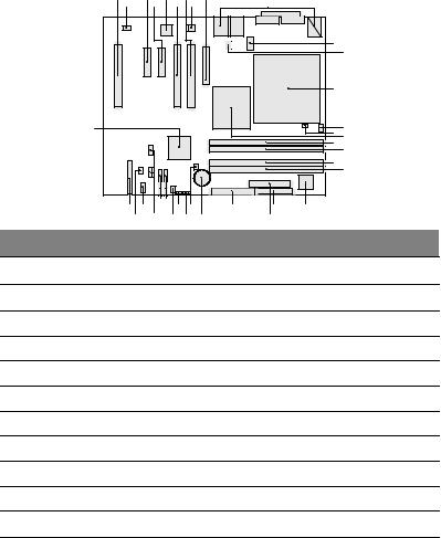
Mainboard layout
The mainboard becomes accessible once you open the system. It should look like the figure shown below
A |
C |
E |
G |
I |
|
B |
D |
F |
H |
J |
|
|
|
|
|
K |
|
|
|
|
|
|
L |
|
|
|
|
M |
|
II |
|
|
|
O |
N |
|
|
|
|
P |
|
|
|
|
|
Q |
R |
|
|
|
|
|
|
|
|
|
|
S |
T |
|
|
|
|
|
HH FF |
|
|
|
|
X |
V |
U |
DD BB Z |
|||||||
GG EE |
|
|
|
CC AA |
Y |
W |
|
Item Description
APCI 32-bit/33 MHz slot 3
BRear fan connector
CPCI Express x4 (w/ x1 throughout) slot 2
DPCI Express x4 (w/ x1 throughout) slot 1
EIntel 82551QM LAN controller
FPCI 32-bit/33 MHz slot 2
GPCI 32-bit/33 MHz slot 1
HMarvell 88E8050 PCI Express Gigabit Ethernet Controller
IPCI Express x8 slot 1
JBack Panel I/O
KTwo x 4 power connector

12 |
2 System tour |
Item Description
LV reg fan connector
MCPU socket
NCPU fan connector
OHardware Management controller
PIntel E7221MC GMCH
QChannel A DIMM 0 (Blue) Socket
RChannel A DIMM 1 (Black) Socket
SChannel B DIMM 0 (Blue) Socket
TChannel B DIMM 1 (Black) Socket
UI/O controller
VFloppy disk drive connector
WTwo x12 Power connector
XParallel ATA IDE connector
YCMOS battery
ZChassis intrusion connector
AABIOS configuration jumper
BBClear CMOS jumper
CCFront fan connector
DDSerial ATA connectors
EEFront panel USB connectors
FFSerial B connector
GGSCSI status LED connector
HHFront panel connector
IIIntel 82801FR ICH6R I/O Controller Hub

13
Jumper settings and CMOS clear
1 |
3 |
|
J6J3 |
|
|
Function/Mode |
Jumper setting |
Configuration |
Normal |
1-2 |
|
The BIOS uses current configuration |
|
|
|
information and passwords for |
|
|
|
booting. |
Configure |
2-3 |
|
After the POST runs, Setup runs |
|
1 |
3 |
automatically. The maintenance menu |
|
|
|
is displayed. |
Recovery |
None |
|
The BIOS attempts to recover the BIOS |
|
1 |
3 |
configuration. A recovery floppy disk is |
|
|
|
required. |
Function/Mode |
Jumper Setting |
|
Configuration |
Normal 1-2
1 |
3 |
The BIOS uses current configuration information.
Clear CMOS |
2-3 |
|
During POST, the CMOS configuration |
|
1 |
3 |
is reset to default values. |
No Jumper |
None |
|
Normal operation, BIOS uses current |
|
1 |
3 |
configuration information. |
14 |
2 System tour |
External and internal structure
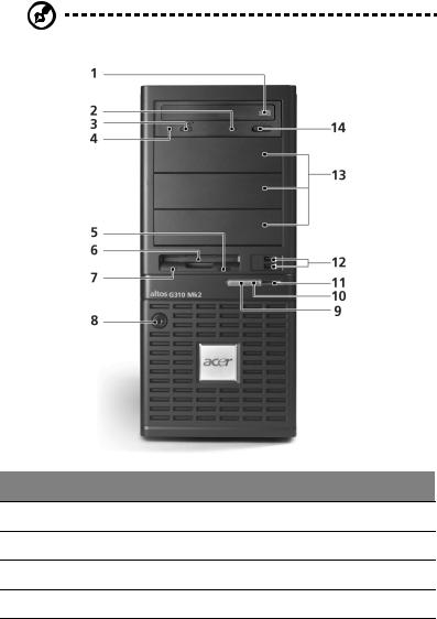
Front bezel
Note: One pair of system keys are provided (attached to the rear panel of the system).
No. Description
1CD-ROM drive
2CD-ROM headphone port
3CD-ROM volume control
4CD-ROM activity indicator

15
No. Description
5FDD eject button
6FDD (floppy disk drive)
7FDD activity indicator
8Security keylock
9HDD activity indicator
10System power indicator
11System power button
12USB 2.0 ports (two)
135.25-inch device bays
14CD-ROM stop/eject button
16 |
2 System tour |
Front panel
No. Description
1CD-ROM drive
2CD-ROM headphone port
3CD-ROM volume control
4CD-ROM activity indicator
5FDD eject button
6FDD (floppy disk drive)
7FDD activity indicator
8Security keylock
17
No. Description
9HDD activity indicator
10System power indicator
11System power button
12USB 2.0 ports (two)
135.25-inch device bays
14CD-ROM stop/eject button
18 |
2 System tour |
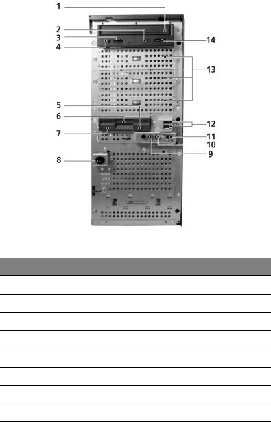
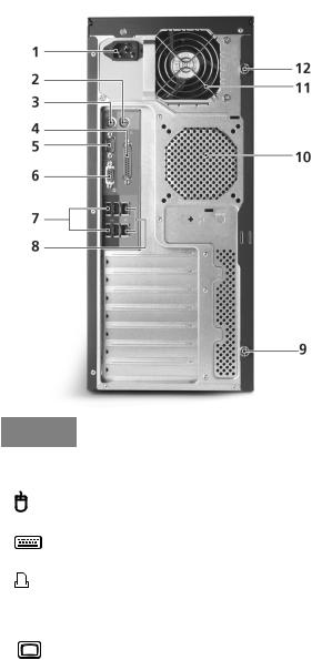
Rear panel
No. |
Icon |
Description |
||||
|
|
|
|
|
|
|
1 |
|
|
|
|
|
Main power supply unit |
|
|
|
|
|
|
|
2 |
|
|
|
|
|
PS/2 mouse port |
|
|
|
|
|
||
|
|
|
|
|
||
|
|
|
|
|
|
|
3 |
|
|
|
|
|
PS/2 keyboard port |
|
|
|
|
|
|
|
4 |
|
|
|
|
|
Parallel/printer port |
|
|
|
|
|
|
|
|
|
|
|
|
|
|
5 |
|
|
|
|
|
Serial port |
|
|
|
|
|
|
|
6 |
|
|
|
|
|
VGA port |
|
|
|
|
|
|
|
Loading...