


Acer AL1711
Service Guide
Service guide files and updates are
available
on the CSD web; for more
Copyright
Copyright © 2003 by Acer Incorporated. All rights reserved. No part of this publication may be reproduced, transmitted, transcribed, stored in a retrieval system, or translated into
any language or computer language, in any form or by any means, electronic, mechanical, magnetic, optical, chemical, manual or otherwise,without the prior written permission of Acer Incorporated.
Disclaimer
The information in this guide is subject to change without notice. Acer Incorporated makes no representations or warranties, either expressed or implied, with respect to the contents hereof and specifically disclaims any warranties of merchantability or fitness for any particular purpose. Any Acer Incorporated software described in this manual is sold or licensed "as is". Should the programs prove defective following their purchase, the buyer (and not Acer Incorporated, its distributor, or its dealer) assumes the entire cost of all necessary servicing, repair, and any incidental or consequential damages resulting from any defect in the software.
Acer is a registered trademark of Acer Corporation.
Intel is a registered trademark of Intel Corporation.
Pentium and Pentium II/III are trademarks of Intel Corporation.
Other brand and product names are trademarks and/or registered trademarks of their respective holders.
|
|
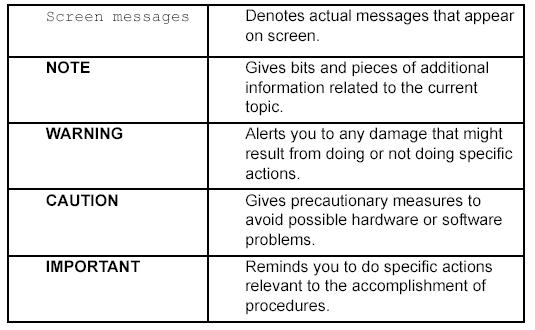
Conventions
The following conventions are used in this manual
:
|
|
Preface
Before using this information and the product it supports, please read the following general
information.
1.This Service Guide provides you with all technical information relating to the BASIC CONFIGURATION
decided for Acer's "global" product offering. To better fit local market requirements and enhance product competitiveness, your regional office MAY have decided to extend the
functionality of a machine (e.g.add-on card, modem, or extra memory capability).
These LOCALIZED FEATURES will NOT be covered in this generic service guide. In such cases, please contact your regional offices or the responsible personnel/channel to
provide you with further technical details.
2.Please note WHEN ORDERING FRU PARTS, that you should check the most up-to-date information available on your regional web or channel. If, for whatever reason, a part number change is made, it will not be noted in the printed Service Guide.
For ACER-AUTHORIZED SERVICE PROVIDERS, your Acer office may have a DIFFERENT part number code to those given in the FRU list of this printed Service Guide.
You MUST use the list provided by your regional Acer office to order FRU parts for repair and service of customer machines.
|
|
!
!
! "
! #
$ ! !
%! # ! &! !
'! ( ) * !
! ( +
!
%! ,-!
- ./. 01 ,-
!
!
|
|
!" " "
" "
! 2 !# 3
! 4 !
# 5 5
!
! , 5 !
5 ! 2
! 2 ! 2
5 !
! ! #
!
!" # "$ %
" "
#"
!& " "
" "
! 2 ( ! 6 5!
! / 3 ! # 5! / !
! 2 7 (
8 !
! 49
5 :: ; %':*-< ! &!-!
! 5 !
! = %* 2 >
|
|
" " '(
•2 5 ! ,
5 5 !
•1 5 !
•9 2 ( ??!??@ ! # :!: @
( ( !
•2 9 2
! #
, !
|
|

Table of Contents
Chapter 1 Monitor Features |
8 |
Monitor Features . . . . . . . . . . . . . . . . . . . . . . . . . . . . . . . . . . . . . . . . . . . . . .8
Factory Preset Timing Table . . . . . . . . . . . . . . . . . . . . . . . . . . . . . . . . . . . .10
Block Diagram . . . . . . . . . . . . . . . . . . . . . . . . . . . . . . . . . . . . . . . . . . . . . . . 11
Mainboard Diagram . . . . . . . . . . . . . . . . . . . . . . . . . . . . . . . . . . . . . . . . . . 12
Software Flowchart . . . . . . . . . . . . . . . . . . . . . . . . . . . . . . . . . . . . . . . . . . . 13
Mainboard Layout . . . . . . . . . . . . . . . . . . . . . . . . . . . . . . . . . . . . . . . . . . . . 15
Invertor Board Layout . . . . . . . . . . . . . . . . . . . . . . . . . . . . . . . . . . . . . . . . . 17
Front Bezel View . . . . . . . . . . . . . . . . . . . . . . . . . . . . . . . . . . . . . . . . . . . . . 18
Rear Bezel View . . . . . . . . . . . . . . . . . . . . . . . . . . . . . . . . . . . . . . . . . . . . . 19
Chapter 2 Operating Instructions |
20 |
External Controls . . . . . . . . . . . . . . . . . . . . . . . . . . . . . . . . . . . . . . . . . . . . 20
Front Panel Control . . . . . . . . . . . . . . . . . . . . . . . . . . . . . . . . . . . . . . . . . . . 20
OSD Menu . . . . . . . . . . . . . . . . . . . . . . . . . . . . . . . . . . . . . . . . . . . . . . . . . 22
Hot-Key Menu . . . . . . . . . . . . . . . . . . . . . . . . . . . . . . . . . . . . . . . . . . . . . . . 25
OSD Message . . . . . . . . . . . . . . . . . . . . . . . . . . . . . . . . . . . . . . . . . . . . . . 26
LOGO . . . . . . . . . . . . . . . . . . . . . . . . . . . . . . . . . . . . . . . . . . . . . . . . . . . . 27
Chapter 3 Machine Disassembly and Replacement |
28 |
|
Chapter 4 |
Troubleshooting |
31 |
Chapter 5 |
Connector Information |
34 |
Chapter 6 |
FRU (Field Replaceable Unit) List |
35 |
Exploded Diagram . . . . . . . . . . . . . . . . . . . . . . . . . . . . . . . . . . . . . . . . . |
35 |
|
Chapter 7 |
Schematic Diagram |
40 |
Analog Input . . . . . . . . . . . . . . . . . . . . . . . . . . . . . . . . . . . . . . . . . . . . . . . 40 Input . . . . . . . . . . . . . . . . . . . . . . . . . . . . . . . . . . . . . . . . . . . . . . . . . . . . . . 41 Scaler MST 8001A/MST8111A . . . . . . . . . . . . . . . . . . . . . . . . . . . . . . . . . 42 Panel Interface . . . . . . . . . . . . . . . . . . . . . . . . . . . . . . . . . . . . . . . . . . . . . . 43 MCU . . . . . . . . . . . . . . . . . . . . . . . . . . . . . . . . . . . . . . . . . . . . . . . . . . . . . 44
Appendix Online Support Information |
45 |
VII

|
|
|
|
||||
|
|
|
|
|
|||
|
|
|
|
|
|||
|
|
|
|
|
|
|
|
|
|
!"#$%&"'( |
|
!"#$%&"'( |
|||
|
)$* |
'"#+ , ) '"#+ - |
'"#+ , ) '"#+ - |
||||
|
. * |
#/'$01 |
|
$ |
|
!''$01 $ |
|
|
|
|
|||||
|
|
|
|
|
|
|
|
|
|
!/'2%$ |
|
/'2%$ |
|||
|
|
||||||
|
|
|
|
|
|
||
|
-3 4 |
% '° , %#'° - |
|
% '° , %!'° - |
|||
|
|
||||||
|
|
|
|
|
|
||
|
5 |
#/ 6 7 8 9: 8 79%& |
#/ 6 7 9; 1 79%+ |
||||
|
|
|
|
|
|
|
|
|
-0 |
58 8. < 7$ |
|
||||
58 8. < 7$ |
|||||||
|
|
|
|
|
|
||
< = |
$" |
,1- |
|
|
,1- |
||
|
|
|
|
|
|
|
|
|
,> ?=$ |
!'@, A :'@, |
|
!'@, A :'@, |
|||
|
|
|
|
|
|
|
|
|
-> ?=$ |
//>&/, |
|
|
//>&/, |
||
|
|
|
|
|
|
|
|
|
|
%+"# |
|
%+"# |
|||
|
|
|
|
|
|
|
|
$B |
|
%!/ ,C |
|
|
%!/ ,C |
||
|
|
|
|
||||
)" 5 = |
|
%#:' ) %'# D&/, |
%#:' ) %'# D&/, |
||||
|
|
|
|
||||
= E |
|
-F %1#. |
-F %1#. |
||||
|
|
|
|
|
|
|
|
|
0 |
/G |
|
|
|
/G |
|
F F |
|
|
|
|
|
|
|
0 |
!G |
|
|
|
!G |
||
|
|
|
|
||||
|
|
|
|
|
|||
< =$ |
|
> =4 %/ |
|
|
|||
|
|
|
|
|
|||
|
|
|
|
|
|
||
|
|
2'"&-> 0 0 8 |
2'"&-> 0 0 8 |
||||
< =-0 |
|
&/ , 8 |
|
&/ , 8 |
|||
|
|
|
|
|
|
|
|
|
|
|
|
|
|
|
|
|
|
, 2 !!&";# |
, 2 !!&";# |
||||
|
|
|
|||||
) =$ |
|
|
|
|
|||
|
|
|
|
||||
|
|
|
- $2 #&'"! |
||||
|
|
- $2 #&'"! |
|||||
|
|
|
|||||
|
|
|
|
|
|
||
3 =$ |
|
%''H#+ -8 &H+!,C |
%''H#+ -8 &H+!,C |
||||
|
|
|
|
|
|||
|
|
|
|
|
|||
|
|
|
|
||||
F |
|
2 /I /'I |
2 /I /'I |
||||
|
"2 >#'I +/I |
"2 >#'I +/I |
|||||
0 |
|||||||
|
,= 0 2 %'J :/J |
,= 0 2 %'J :/J |
|||||
|
|
||||||
|
|
|
|
|
|||
|
|
!' G K |
/ , K%/# |
|
|||
|
|
|
|
|
|||
G * " G" |
|
/"'B |
|
|
|||
|
|
|
|
|
|
|
|
|
|
|
|
• = 0L= @ |
• = 0L= @ |
|||
|
|
• |
• |
|||
|
3$* |
|
|
|
|
|
|
|
• |
• |
|||
|
|
• 3 .= |
• 3 .= |
|||
|
|
• F 1 F) |
• F 1 F) |
|||
|
|
|
|
|||
|
|
• |
• |
|||
|
|
• . * |
• . * |
|||
|
|
• $= |
• $= |
|||
|
|
• $B |
• $B |
|||
|
|
• ," |
• ," |
|||
|
|
• -" |
• -" |
|||
|
|
• < =$0 |
• < =$0 |
|||
F) 2 |
=$ |
• = |
• = |
|||
• > 0 =$0 |
• > 0 =$0 |
|||||
|
|
|||||
|
|
• G |
• G |
|||
|
|
• |
• |
|||
|
|
• 5 . = |
• 5 . = |
|||
|
|
• 5 |
• 5 |
|||
|
|
• = |
• = |
|||
|
|
• 7 |
• 7 |
|||
|
|
• F) |
• F) |
|||
|
|
|
|
|||
3 = |
) = |
/ G |
/ G |
|||
|
|
|
|
|||
=0 = = |
|
5 0 3 %G$* |
5 0 3 %G$* |
|||
|
|
|
||||
5 =$ |
8 M-1 8 F8 N;;8 |
8 M-1 8 F8 N;;8 |
||||
|
|
|
|
|
|
|
|
|
|
|
|
) |
|
|
|||
|
|
|
+ |
1 |
+ |
1 |
+ |
|
* |
! |
|
, |
2 |
, |
2 |
2 |
|
-.# / 0 ) |
|
-.# 3 ) |
|
( |
||||
|
|
|
|
|
||||
|
|
|
|
|
|
|
$*) % |
|
|
45/ 56/74/) |
6// 080 |
3 549 |
+ |
09 95/ |
+ |
80 3:0 |
|
;< |
|
|
|
|
|
|
|
|
45/ 56/7:8) |
6 8 08/ |
: 643 |
+ |
:8 6/9 |
+ |
3 0// |
||
|
45/ 56/7:0) |
65/ 0// |
: 0// |
+ |
:0 // |
+ |
3 0// |
|
|
|
|
|
|
|
|
|
|
|
6// 4//704) |
3/85 480 |
0 304 |
+.2 |
04 80/ |
+.2 |
4 /// |
|
1 ;< |
6// 4//74/) |
3/04 486 |
: 6:9 |
2 |
4/ 3: |
2 |
5/ /// |
|
|
|
|
|
|
|
|
||
6// 4//7:8) |
3/5/ 444 |
56 /:: |
2 |
:8 366 |
2 |
0/ /// |
||
|
||||||||
|
6// 4//7:0) |
3/04 480 |
54 6:0 |
2 |
:0 /// |
2 |
59 0// |
|
|
|
|
|
|
|
|
|
|
|
3/85 :4674/) |
3 55 6/4 |
56 4 |
+ |
4/ //5 |
+ |
40 /// |
|
=;< |
3/85 :467:/) |
3 86 6/4 |
04 5:4 |
+ |
:/ /49 |
+ |
:0 /// |
|
|
|
|
|
|
|
|
|
|
|
3/85 :467:0) |
3 38 6// |
4/ /8 |
2 |
:0 /89 |
2 |
:6 :0/ |
|
|
3308 6457:0) |
34//=9// |
4: 0 |
2 |
:0 |
2 |
3/6 /// |
|
1=;< |
386/ 3/8574/) |
3466 3/44 |
4 963 |
2 |
4/ /8/ |
2 |
3/6 /// |
|
386/ 3/857:0) |
3466 3/44 |
:9 9:4 |
2 |
:0 /80 |
2 |
3 0 /// |
||
|
||||||||
|
|
|
) |
|
|
|
||
>1 |
:8/ 5//7:/) |
9// 559 |
3 549 |
+ |
:/ /6: |
|
2 |
86 88 |
|
|
|
|
|
|
|
|
|
>1 |
45/ 0/7:/) |
6// 559 |
3 549 |
2 |
:/ /6: |
|
+ |
80 3:0 |
=;< |
3/85 :467:8) |
3 /5 :96 |
0: 030 |
2 |
:8 3 |
|
2 |
:0 /// |
VGA |
45/ 56/74:) |
645 080 |
0 /// |
+ |
44 44: |
+ |
/ 85/ |
|
1 ;< |
6 8 4857:0) |
3308 44: |
59 :80 |
+ |
:5 003 |
+ |
0: 86 8 |
|
|
||||||||
|
|
|
|
|
|
|
||
|
|
|
|
|
|
|
|
|
=;< |
3/85 :4674/) |
3 38 63 |
56 :6/ |
+ |
4/ //3 |
+ |
45 /// |
|
|
3/85 :467:0) |
3 86 6/5 |
4/ 853 |
+ |
:5 98: |
+ |
6/ /// |
|
|
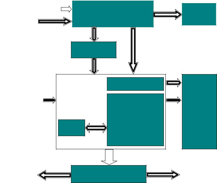
Monitor Block Diagram
! " " " #
" !$ #
% &'($#
|
|
|
|
|
|
|
|
|
|

|
|
|
|
|
|
|
|
|
|
|
|
|
|
|
LCD |
|
|
|
|
|
Controller |
|
MCU |
#1 |
|
#>1 |
|
|
|
|
|
|
#' 1 ( |
|
|
< ( |
'( 2<+?'
12?<@?! |
|
12?<@?! |
|
|
|
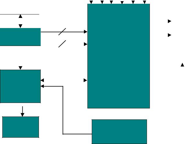
MAIN BOARD DIAGRAM |
|
|
|
|
|
|
|
|
|
|
|
|
|
|
|
||||
|
|
|
|
|
|
|
|
|
|
|
|
|
|
|
|
|
|
|
|
|
|
|
|
|
|
|
|
|
|
|
|
|
|
|
|
|
|
|
|
|
|
|
|
|
|
|
|
|
|
|
|
|||||||||||
|
|
|
|
|
|
|
|
|
|
|
|
|
|
|
|
|
|
|||
|
|
|
|
|
|
|
|
|
|
|||||||||||
|
|
|
|
|
|
|
|
|
|
|
|
|
|
|
|
|
|
|
||
|
|
|
|
|
|
|
|
|
|
|
|
|
|
|
|
|
|
|||
|
|
|
|
|
|
|
|
|
|
|
|
|
|
|
|
|
||||
|
|
|
|
|
|
|
|
|
|
|
|
|
|
|
||||||
|
|
|
|
|
|
|
|
|
|
|
|
|
|
|
|
|
|
|
|
|
|
|
|
|
|
|
|
|
|
|
|
|
|
|
|
|
|
|
|
|
|
|
|
|
|
|
|
|
|
|
|
|
|
|
|
|
|
|
|
|
|
|
|
|
|
|
|
|
|
|
|
|
|
|
|
|
|
|
|
|
|
||
|
|
|
|
|
|
|
|
|
|
|
|
|
|
|
|
|
|
|||
|
|
|
|
|
|
|
|
|
|
|
|
|
|
|
|
|||||
|
|
|
|
|
|
|
|
|
|
|
|
|
|
|
|
|
|
|
|
|
|
|
|
|
|
|
|
|
|
|
|
|
|
|
|
|
|
|
|
||
|
|
|
|
|
|
|
|
|
|
|
|
|
|
|
|
|
|
|
||
|
|
|
|
|
|
|
|
|
|
|
|
|
|
|
|
|
|
|||
|
|
Hsyn /Vsyn |
|
|
|
|
|
|
|
|
|
|
|
|
|
|
||||
|
|
|
|
|
|
|
|
|
|
|
|
|
|
|
|
|
|
|
|
|
|
|
|
|
|
|
|
|
|
|
|
|
|
|
|
|
|
|
|
|
|
|
|
|
|
|
|
|
|
|
|
|
|
|
|
|
|
|
|
|
|
|
|
|
|
|
|
|
)* (* |
|
|
||||||||||||
|
|
|
|
|
|
|
|
|
|
|
|
|
|
|
|
|
|
|
|
|
|
|
|
|
|
|
|
|
|
|
|
|
|
|
|
|
|
|
|
|
|
|
|
|
|
|
|
|
|
|
|
|
|
|||||||||
|
|
|
|
|
|
|
|
|
|
|||||||||||
|
|
|
|
|
|
|
|
|
|
|
||||||||||
|
|
|
|
|
|
|
|
|
|
|
|
|
|
|
|
|
|
|
|
|
|
|
|
|
|
|
|
|
|
|
|
|
|
|
|
|
|
|
|
||
|
|
|
|
|
|
|
|
|
|
|
|
|
|
|
|
|||||
|
|
|
|
|
|
|
|
|
|
|
|
|
|
|
|
|||||
|
|
|||||||||||||||||||

|
|
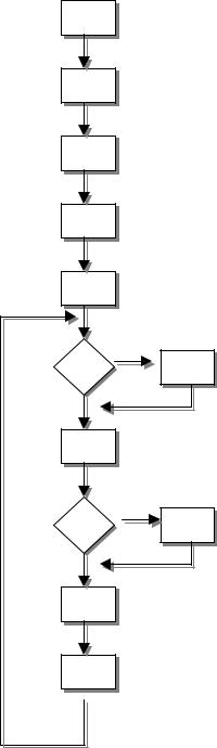
Software Flow Chart
+&, |
|
+', |
Y |
|
|
N |
|
+-, |
|
+., |
Y |
|
|
N+/, |
|
+1, |
+0, |
+2, |
|
+4, |
+&3, |
+&&, |
|
+&', |
|
|
|
1.Initialize MCU settings, including I/O, Timer, ISR and Serial Port settings.
2.Read EEPROM content to recover monitor settings, including brightness, contrast, color temperature and OSD position …. etc.
3.Initialize system variable, including system flag, OSD timeout counter, burin mode status… etc.
4.Initialize OSD menu variable for user operation
5.Initialize device on the board, now only MST scaler chip will be initialized
6.Check if system is in power off status from first AC power up. If yes, then go to 7, else go to 8.
7.If yes, system will be forced to enter power off status
8.Mode detection
9.Check if input timing has been changed, if yes then go to 10, else go to 11
10.Setup MST scaler for display according input timing
11.OSD handler for OSD operation.
12.Debug handler, only debug only
|
|

Monitor Board Layout
|
|
|
! |
|
|
" # |
$%& # '(#) *+*$ |
|
|
" # |
$%& # *+ *$& |
|
|
# |
RT9164-25CG |
|
|
|
|
|
$# ) (($ |
|
|
( # |
$& |
|
|
# |
& )## ,-# ) |
|
|
# |
$$&$#$# |
|
|
$# |
- |
|
|
$( # |
* .$/ |
|
|
$( |
( |
|
|
$0 ( |
* ' 11 |
|
|
$# |
* |
|
|
$ |
-# ' 11 |
|
|
# |
$* ) # / * 2 0 |
|
|
|
$* ) # / * 2 0 |
|
|
|
|

Inverter Board Layout
5 |
|
6 '3& |
|
|
|
6 '3' |
|
|
|
43& |
*712.& 89 *9* 5 |
|
|
43' |
6 &'- 92' |
|
|
43- |
) .-& |
|
|
&3' |
)5% 5 ':16 |
|
|
'3& |
;%<5 |
|
|
'3' |
;%<5 |
|
|
'3- |
#'6 % 20'&3$3'-1 6 |
|
|
'3. |
;%<5 |
|
|
-3& |
6) 5 =% > |
|
|
-3' |
- 6 |
|
|
8 43& |
8 75 '>8631 |
|
|
43& |
2 ) |
|
|
43/ |
&33?< @$'3A .33( |
|
|
43& |
BC< |
|
|
D'&& |
'* /031 6 *% 9 |
|
|
|
|
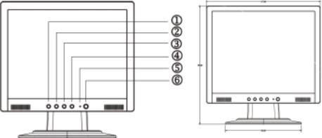
Front Bezel
Item |
Description |
|
|
1 |
Auto Adjust Key/Exit |
|
|
2 |
>/ Volume |
|
|
3 |
</ Volume |
|
|
4 |
MENU/ENTER |
|
|
5 |
LED |
|
|
6 |
POWER |
|
|
|
|
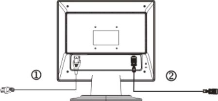
Rear Bezel
Item |
Description |
1 |
AC POWER CORD |
2 |
Signal Cable |
|
|
|
|
* 3 4= = * 77" * *$4=$0 7 7 * " .
$* * 8 *$=$4 0L= 0 = 7$"
• * 3$0 * = 0 4$ $0"
• $* 0$4 7 * * 0$0"
• * 3 4= = * " * 3 0$3 * = "
F) .=
|
! " # |
|
|
|
|
|
$ |
|
% & |
|
' |
( |
) * + |
|
|
|
|
|
|
|
|
|
|
|
|
* 4= = * "
$= 3*$10 >$0L= 7=$3* F) =
3*-= 0L= = "
•
,-. /-, 0 + */ 0 / 12& 133 + 0.-4. /+ 4/ . 0 , 0 */ 0 12& 1 +
. . 5 0, 0 */ 0 5 0, 0 .,-.
|
|
•
,-. /-, 0 + */ 0 / 12& 133 + 0.-4. /+ 4/ . 0 , 0 */ 0 12& 1 +
. . 5 0, 0 */ 0 5 0, 0 .,-.
• !"
%" G* =$= 8 * 4= 3$FO< >@FP
FO< = "
#" G* = 77 = 8 * 4= 7 #$0 $* = 0L= 7=$"
* = 0L= 7=$= 0 * , 8-8$B 0$= "
• # "$%
Q 3 0 "
Q 77 0 "
•*$* =$=$* 0 0=$8$=4L$0$ = * 8 )$0=$*$4 *$B"
• * *$0$B 8 * 3$* 0 7 = * * = "
• ) =$8$B = 3$B 0 * 7$"
•B * B 38 0$ $3 * 7$*" =44 4 0 3 *$* *
0 0 3 * 0 0 = " = =$* * 8 4 8 4$8$ * 3 0 *$4 " 7$= 8 3 = = * 4 7$"
%" * F >4= $* 3 0 3" 7 = " #" $* 0 0 7=$" 7 = "
!" * F >4= $* 7=$* = 3 0L= "
" $* * 7 *$= 7=$"
/" ) 0 8$* ) 7=$" <7 = 3 0L= * 7=$8 #> "
|
|
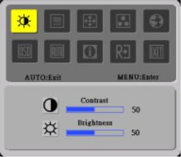
ADJUSTING THE PICTURE
< #> *
|
|
 Loading...