


 S300
S300
Dual Mono Integrated Amplifier
GB |
Owner’s Manual |
F |
|
Manuel d’Installation |
|
D |
|
Bedienungsanleitung |
|
E |
|
Manual del Usuario |
|
I |
|
Manuale delle Istruzioni |
|
P |
|
Manual do Proprietário |
|
S |
|
Bruksanvisning |

IMPORTANT SAFETY INSTRUCTIONS
CAUTION |
|
ATTENTION: |
RISK OF ELECTRIC |
|
RISQUE DE CHOC ELECTRIQUE |
SHOCK DO NOT OPEN |
|
NE PAS OUVRIR |
|
|
|
CAUTION: TO REDUCE THE RISK OF ELECTRIC SHOCK, DO NOT REMOVE COVER (OR BACK). NO USER SERVICEABLE PARTS INSIDE. REFER SERVICING TO QUALIFIED SERVICE PERSONNEL.
Warning: To reduce the risk of fire or electric shock, do not expose this unit to rain or moisture.
The lightning flash with an arrowhead symbol within an equilateral triangle, is intended to alert the user to the presence of uninsulated “dangerous voltage” within the product’s enclosure that may be of sufficient magnitude to constitute a risk of electric shock to persons.
The exclamation point within an equilateral triangle is intended to alert the user to the presence of important operating and maintenance (servicing) instructions in the literature accompanying the product.
Do not place this unit on an unstable cart, stand or tripod, bracket or table. The unit may fall, causing serious injury to a child or adult and serious damage to the unit. Use only with a cart, stand, tripod, bracket or table recommended by the manufacturer or sold with the unit. Any mounting of the device on a wall or ceiling should follow the manufacturer’s instructions and should use a mounting accessory recommended by the manufacturer.
An appliance and cart combination should be moved with care. Quick stops, excessive force and uneven surfaces may cause the appliance and cart combination to overturn.
Read and follow all the safety and operating instructions before connecting or using this unit. Retain this notice and the owner’s manual for future reference.
All warnings on the unit and in its operating instructions should be adhered to.
Do not use this unit near water; for example, near a bath tub, washbowl, kitchen sink, laundry tub, in a wet basement or near a swimming pool.
The unit should be installed so that its location or position does not interfere with its proper ventilation. For example, it should not be situated on a bed, sofa, rug or similar surface that may block the ventilation openings; or placed in a built-in installation, such as a bookcase or cabinet, that may impede the flow of air through its ventilation openings.
The unit should be situated from heat sources such as radiators, heat registers, stoves or other devices (including amplifiers) that produce heat.
The unit should be connected to a power supply outlet only of the voltage and frequency marked on its rear panel.
The power supply cord should be routed so that it is not likely to be walked on or pinched, especially near the plug, convenience receptacles, or where the cord exits from the unit.
Unplug the unit from the wall outlet before cleaning. Never use benzine, thinner or other solvents for cleaning. Use only a soft damp cloth.
The power supply cord of the unit should be unplugged from the wall outlet when it is to be unused for a long period of time.
Care should be taken so that objects do not fall, and liquids are not spilled into the enclosure through any openings.
This unit should be serviced by qualified service personnel when:
A.The power cord or the plug has been damaged; or
B.Objects have fallen, or liquid has been spilled into the unit; or
C.The unit has been exposed to rain or liquids of any kind; or
D.The unit does not appear to operate normally or exhibits a marked change in performance; or
E.The device has been dropped or the enclosure damaged.
DO NOT ATTEMPT SERVICING OF THIS UNIT YOURSELF. REFER SERVICING TO QUALIFIED SERVICE PERSONNEL
ATTENTION
POUR ÉVITER LES CHOC ELECTRIQUES, INTRODUIRE LA LAME LA PLUS LARGE DE LA FICHE DANS LA BORNE CORRESPONDANTE DE LA PRISE ET POUSSER JUSQU’AU FOND.
CAUTION
TO PREVENT ELECTRIC SHOCK, MATCH WIDE BLADE OF PLUG TO WIDE SLOT FULLY INSERT.
If an indoor antenna is used (either built into the set or installed separately), never allow any part of the antenna to touch the metal parts of other electrical appliances such as a lamp, TV set etc.
CAUTION
POWER LINES
Any outdoor antenna must be located away from all power lines.
OUTDOOR ANTENNA GROUNDING
If an outside antenna is connected to your tuner or tunerpreamplifier, be sure the antenna system is grounded so as to provide some protection against voltage surges and built-up static charges. Article 810 of the National Electrical Code, ANSI/NFPA No. 70-1984, provides information with respect to proper grounding of the mast and supporting structure, grounding of the lead-in wire to an antenna discharge unit, size of grounding conductors, location of antenna discharge unit, connection to grounding electrodes and requirements for the grounding electrode.
a.Use No. 10 AWG (5.3mm2) copper, No. 8 AWG (8.4mm2) aluminium, No. 17 AWG (1.0mm2) copper-clad steel or bronze wire, or larger, as a ground wire.
b.Secure antenna lead-in and ground wires to house with stand-off insulators spaced from 4-6 feet (1.22 - 1.83 m) apart.
c.Mount antenna discharge unit as close as possible to where leadin enters house.
d.Use jumper wire not smaller than No.6 AWG (13.3mm2) copper, or the equivalent, when a separate antenna-grounding electrode is used. see NEC Section 810-21 (j).
EXAMPLE OF ANTENNA GROUNDING AS PER NATIONAL ELECTRICAL CODE INSTRUCTIONS CONTAINED IN ARTICLE 810 - RADIO AND TELEVISION EQUIPMENT.
NOTE TO CATV SYSTEM INSTALLER: This reminder is provided to call the CATV system installer’s attention to Article 820-40 of the National Electrical Code that provides guidelines for proper grounding and, in particular, specifies that the ground cable ground shall be connected to the grounding system of the building, as close to the point of cable entry as practical.
Upon completion of any servicing or repairs, request the service shop’s assurance that only Factory Authorized Replacement Parts with the same characteristics as the original parts have been used, and that the routine safety checks have been performed to guarantee that the equipment is in safe operating condition. REPLACEMENT WITH UNAUTHORIZED PARTS MAY RESULT IN FIRE, ELECTRIC SHOCK OR OTHER HAZARDS.
2

REAR PANEL CONNECTIONS
©1998 NAD S300
FRONT PANEL CONTROLS
©1998 NAD S300
3
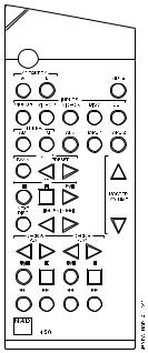
REMOTE CONTROL
4
5

NAD S300 Dual Mono Integrated Amplifier
QUICK START
1.Connect the speakers to the rear Speaker sockets and sources to the relevant rear input sockets.
2.Plug in the AC Mains cable.
3.Press the POWER button to turn the S300 on.
4.Press the required input selector.
A NOTE ON INSTALLATION
This unit may be installed on any level surface that is strong enough to support its weight. Avoid placing the unit in direct sunlight or near sources of heat and damp. Since its power transformers generate a significant magnetic hum field, a turntable (especially one with a moving-coil pick-up cartridge) or a TV should not be located adjacent to the amplifier or directly above it.
The heat-sink fins make it awkward to lift the S300 by grasping the left and right sides. You may find it more practical to place your hands under the front and rear panels. Much of the amplifier’s weight is near the front panel.
CAUTION: The amplifier’s weight must always rest on its bottom feet. Never put the amplifier down on its rear panel, with its front panel facing up. Doing so risks damage to the input/output connectors.
The amplifier generates some heat, even when idling, requiring internal and external ventilation. Allow adequate ventilation. Do not place it in an enclosed position such a bookcase or cabinet that may impede the air-flow through the ventilation slots.
Do not permit the ventilation slots on the top cover to be obstructed by papers or articles of clothing. If you want to locate the amplifier on a carpeted floor, place a board under the amplifier in order to prevent it from sinking into the carpet, blocking the air inlets on its bottom.
CAUTION: To prevent a fire or shock hazard, do not permit liquid or moisture to enter the amplifier. If liquid is accidentally spilled on it,
GB immediately shut off the power and unplug the AC Mains cable. Have the unit inspected by a qualified service technician before attempting to use it again.
Switch the unit off before making any connections. The RCA connectors on your S300 are colour coded for convenience. Red and white are Right and Left audio respectively, and yellow for NAD-Link. Always use high quality leads and connectors for optimum performance and reliability. Ensure that leads and connectors are not damaged in any way and all connectors are firmly pushed home. For best performance, use quality speaker leads of 16 gauge or 2 sq.mm. thickness or more.
If the unit is not going to be used for some time, disconnect the plug from the AC socket.
Do not open the amplifier or attempt to modify or repair it yourself. Refer all servicing to a qualified technician. Do not remove the cover, there are no user-serviceable parts inside.
Use a dry soft cloth to clean the unit. If necessary, lightly dampened the cloth with soapy water. Do not use solutions containing benzol or other volatile agents.
REAR PANEL CONNECTIONS
1. IEC AC MAINS (POWER) INPUT
The S300 comes supplied with a separate AC Mains cable. Before connecting the cable to a live wall socket ensure that it is firmly connected to the NAD S300’s AC Mains input socket first. Always disconnect the AC Mains cable plug from the live wall socket first before disconnecting the cable from the S300 Mains input socket.
VOLTAGE CONVERSION
A notice printed on the rear indicates the AC power-line voltage that the preamplifier requires. However, every model S300 amplifier has a “universal” power supply that can be modified easily for operation in other countries. If you wish to transport your S300 to a nation that employs a different power-line voltage, an authorised NAD dealer or service agency can convert it for such use.
2. BALANCED CD INPUT
Input for a CD or other line-level signal source that uses balanced XLR output connectors, like NAD S500. In case you do not wish to use a CD player featuring balanced outputs, use the AUX input for RCA connectors instead.
The wiring standard used for the balanced connectors is: Pin 1:Chassis Earth (Ground)
Pin 2:Hot (Live)
Pin 3:Signal Ground (Return)
THE BENEFITS OF BALANCED CONNECTIONS
With a conventional (unbalanced) connection, audio signal current flows from the CD player to the amplifier via the cable’s centre conductor. To complete the circuit, audio signal current flows back to the CD player ground via the cable’s outer conductor. The outer conductor also serves as the cable’s shield.
When two audio components are connected together, power-supply noise and “leakage” hum may also flow on the cable shields, combining with the return audio current. The resulting distortion and noise may depend on the orientation of AC power plugs in their sockets. Designers of some audiophile cables combat this contamination by leaving the shield unconnected at one end. Since the shield is grounded at only one end, the performance of such a cable may depend on the direction of its connection, i.e. whether the shield is grounded at the CD player or at the amplifier.
A three-wire balanced connection avoids all of these uncertainties. The signal “hot” and return currents are both carried on inner conductors. The separate cable shield, connected to the amplifier chassis at both ends, protects the audio signal from all forms of interference and power-supply noise.
3. VIDEO INPUT
Input for the audio signal from a stereo VCR (or stereo TV/Satellite/Cable receiver) or other line-level audio source. Using twin RCA-to-RCA leads, connect to the left and right ‘Audio Outputs’ of the unit to these inputs.
NOTE: These are audio inputs only.
6

4. AUX INPUT
Input for additional line level input signals or a CD player with no balanced output. Use a twin RCA-to-RCA lead to connect the auxiliary unit’s left and right ‘Audio Outputs’ to these inputs.
5. TUNER INPUT
Input for a Tuner or other line-level signal source. Use a twin RCA-to- RCA lead to connect the Tuner left and right ‘Audio Outputs’ to these inputs.
6. TAPE, TAPE RECORD
Connections for analogue recording and playback to an audio tape recorder of any type. Using twin RCA-to-RCA leads, connect the left and right ‘Audio Outputs’ of the tape machine to the TAPE connectors for playback and tape monitoring. Connect the left and right ‘Audio Inputs’ of the tape machine to the TAPE REC connectors for recording.
7. NAD-LINK IN, OUT
The NAD-Link connector is used to pass commands from the remote control handset to and from other units fitted with NAD-Link connectors. This allows centralised control of a complete system or gives system control from more than one room. To function with other units, connect the S300’s NAD-Link OUT to the NAD-Link IN on the other unit. NAD-Link connectors can be daisy-chained, IN to OUT, so that a whole system can be controlled from the remote control facilities of one unit.
A single NAD-Link connection from a hi-fi system in a second room will allow remote control of Multi Room systems.
8. SPEAKERS
Speaker terminals for speakers with an impedance of 4 ohms or more. Connect the right speaker to the terminals market ‘R +’ and ‘R-’ ensuring that the ‘R+’ is connected to the ‘+’ terminal on your loudspeaker and the ‘R-’ is connected to the loudspeaker’s ‘-’ terminal.
Connect the terminals marked ‘L+’ and ‘L-’ to the left speaker in the same way.
Always use heavy duty (16 gauge/2 sq.mm. or thicker) stranded wire to connect loudspeakers to your S300.
The high current binding post terminals can be used as a screw terminal for cables terminating in spade or pin connectors or for cables with bare wire ends.
SPADE CONNECTORS
These should be slotted under the terminal’s screw bushing, which is then fully tightened. Ensure the connector is tightly secured and there is no danger of bare metal from spade connectors touching the back panel or another connector as this may cause damage.
BARE WIRES AND PIN CONNECTORS
Bare wires and pin connectors should be inserted into the hole in the shaft of the terminal. Unscrew the speaker terminal’s plastic bushing until the hole in the screw shaft is revealed. Insert the pin or bare cable end into the hole and secure the cable by tightening down the terminal’s bushing.
Avoid any danger of bare metal from the speaker cables touching the back panel or another connector. Ensure that there is only 1/2” (1cm) of bare cable or pin and no loose strands of speakers wire.
9. GROUND CONNECTOR
The S300 is provided with a GROUND terminal on the rear panel. This terminal is connected directly to the chassis of the S300. In the event of radio hum or radio interference, this terminal can be connected to a ‘true earth’ such as a copper plated rod driven several feet into the ground.
FRONT PANEL CONTROLS
1. POWER
Pressing the POWER button turns the unit On. The blue LED above the POWER button lights up. After a pause to stabilise all circuits, the relays click on to open for the signal to the loudspeakers, and the LED goes off. Pressing the POWER button again will turn the amplifier Off.
The Power LED is dark when the amplifier is on, and lights up blue when it is in Standby mode and during the start-up procedure. In case of a short-circuit of the speaker cables, the LED flashes to indicate that the protection mode is active.
When you switch on the unit by pressing the POWER button, CD is always selected as the active input, indicated by the LED above the CD button lighting up.
Pressing the Standby button on the remote handset while the S300 is On will switch it into Standby mode and the LED above the POWER button lights up. This shows that power is being supplied to the S300, but the system is currently in the Standby mode. The next time you switch the S300 on with the Standby button, the internal memory selects the input that was active when you switched it to Standby mode. If you switch off and on with the front panel POWER button, this memory is deleted, and the unit starts in CD mode.
When in Standby mode, you may press any of the input selector |
|
buttons on the front panel to “wake up” your S300 with that input |
|
active. |
GB |
CAUTION: When in Standby mode , power is still supplied to your |
|
S300. You should switch it off using the front panel POWER button |
|
when it is not being used for long periods of time. |
|
2. INPUT SELECTORS |
|
These buttons select the active input to the S300 and the signal sent |
|
to the loudspeakers and the Tape Rec output. |
|
LED’s above each button will indicate which input is currently |
|
selected. |
|
CD Selects the (balanced only) CD input (or other line-level source) |
|
connected to the balanced CD sockets as the active input. |
|
VIDEO Selects the VCR (or stereo TV/Satellite/Cable receiver) |
|
connected to the VCR sockets as the active input. |
|
AUX Selects a line-level source connected to the AUX sockets, such |
|
as a CD player without balanced outputs as the active input. |
|
TUNER Selects the tuner (or other line-level source) connected to the |
|
Tuner sockets as the active input. |
|
7

TAPE FUNCTIONS
3. TAPE MONITOR
Selects the output from a tape recorder when playing back tapes or monitoring recordings being made through the Tape sockets. Press the TAPE MONITOR button once to select it and again to return to the normal input selection.
TAPE MONITOR is a monitor function which does not override the current input selection. For example, if the CD is the active input when TAPE MONITOR is selected, then the CD signal will continue to be selected and sent to the TAPE REC sockets, but it is the sound from recorder connected to TAPE will be heard from the loudspeakers.
To show which input is active when in tape monitor mode, its indicator light will stay lit.
TO MAKE A RECORDING
When any source is selected, its signal is also fed directly to any tape machine connected to the TAPE REC outputs for recording.
Please note that the S300 has no built-in RIAA phono amplification. If you wish to listen to LP records, it is necessary to add a separate phono preamplifier, such as an NAD PP1. The phono preamplifier may then be connected to the AUX or VIDEO input.
STANDBY Switches the S300 between On and Standby modes. (Caution: Switch the S300 off using the front panel POWER button when it is not being used for long periods of time.)
MUTE Press the MUTE button to temporarily switch off the sound to the speakers. Press MUTE button again to restore sound.
VIDEO 1 Selects VIDEO as the active input.
VIDEO 2 and 3 Not active with S300.
DISC Not active with S300.
CD Selects CD as the active input.
TUNER FM Selects the TUNER input of the S300 and the FM waveband on a separate NAD Tuner.
TUNER AM Also selects TUNER input on the S300 and the AM waveband on a separate NAD Tuner.
AUX Selects AUX as the active input.
TAPE 1 Selects TAPE MONITOR as the active input. Press it to select, press it again to revert to normal input selection.
TAPE 2 Not active with S300.
MASTER VOLUME  or
or  respectively increases or decreases the Volume setting. The motorised Volume Control on the front panel will indicate the level set.
Other than the commands relating to the NAD S300 amplifier itself, there are other buttons which will operate most NAD CD players, Tuners and Cassette decks equipped with NAD Link.
BALANCE AND VOLUME
BALANCE
The S300 is designed with no balance control. As most serious listening takes place in the optimum position between the speakers, we have decided to leave out this potentially detrimental control.
4. VOLUME
The VOLUME control adjusts the overall loudness of the signals being fed to the loudspeakers. It is motor driven and can be adjusted from the remote control handset. The VOLUME control does not affect recordings made using the Tape output.
GB 5. IR
Sensor for receiving the infra-red signals from your remote handset. The LED above the sensor will flash when a signal is being received from the remote handset, even if the signal goes to another NAD unit, e.g. through NAD-LINK.
REMOTE CONTROL HANDSET
The Remote control handset handles all the key functions of the S300 and has additional controls to remotely operate NAD Tuners, Cassette and CD machines. Alkaline batteries are recommended for maximum operating life. Two AAA (LR03) batteries should be fitted in the battery compartment of the Remote control handset. When replacing batteries, check that they have been put in the right way round, as indicated on the base of the battery compartment. Please refer to previous sections of the manual for a full description of individual functions.
NOTE: The remote control handset supplied is the NAD universal remote and can be used on any remote controllable NAD system. Not every function on it is available on your S300.
TUNER CONTROL
(for use with NAD Tuner).
BANK Selects a bank of preset stations.
PRESET |
or |
Selects respectively lower or higher number |
station preset. |
|
|
CD PLAYER CONTROL
(for use with NAD CD Player).
engages Pause. engages Stop.
engages Play or toggles between Play and Pause.

 or
or 
 engages Track skip; Press once respectively to return to
the start of the current or previous track or to go to the next track. NEXT DISC Go to next disc (for NAD CD changers).
CASSETTE DECK CONTROL
(For use with single (DECK B) or double transport (A and B) NAD Cassette Decks).
or  engages Reverse Play or Forward Play.


 Record / Pause. Press to put cassette deck into record-pause. Press Play to start recording.
stops Play or Recording.
 engages Rewind.
  engages Fast Forward.
NOTE: Direct sunlight or very bright ambient lighting may affect the operating range and angle for the remote control handset.
8

TROUBLESHOOTING
Problem |
Cause |
Solution |
|
|
|
NO SOUND |
• Power AC Mains cable unplugged or |
• Check if AC Mains cable is plugged in and |
|
power not switched on |
power switched on |
|
• TAPE MONITOR is selected |
• De-select TAPE MONITOR mode |
|
• Mute on |
• Switch off Mute |
|
• Internal fuse blown |
• Consult dealer |
|
|
|
NO SOUND IN ONE CHANNEL |
• Speaker not properly connected or |
• Check connections and speakers |
|
damaged |
|
|
• Input lead disconnected or damaged |
• Check leads and connections |
|
|
|
WEAK BASS / POOR STEREO IMAGE |
• Speakers wired out of phase |
• Check connections to all speakers |
|
|
in the system |
|
|
|
REMOTE CONTROL HANDSET NOT |
• Batteries flat, or incorrectly inserted. |
• Check or replace batteries |
WORKING |
• IR transmitter or receiver windows |
• Remove obstruction |
|
obstructed |
|
|
|
|
GB
9

Amplificateur Double Mono Integre NAD S300
DEMARRAGE RAPIDE
1.Brancher les haut-parleurs sur les prises pour haut-parleurs à l’arrière et les sources sur les prises d’entrée correspondantes à l’arrière.
2.Brancher le cordon d’alimentation CA.
3.Appuyer sur le bouton-poussoir “Marche/Arrêt” [POWER] pour mettre le S300 sous tension.
4.Appuyer sur le sélecteur d’entrée requis.
Pour obtenir les meilleures performances, utiliser des câbles pour haut-parleurs d’une épaisseur de calibre 16 ou 2 mm2 ou plus.
Si l’appareil doit rester inutilisé pendant un certain temps, débrancher le cordon d’alimentation de la prise de secteur murale.
Ne pas ouvrir l’amplificateur ou essayer de le modifier ou de le réparer vous-même. Confier tout travail d’entretien à un technicien qualifié. Ne pas retirer le couvercle. A l’intérieur, il n’y a aucun élément sur lequel l’utilisateur peut intervenir.
UN MOT SUR L’INSTALLATION
Cet appareil peut être posé sur n’importe quelle surface suffisamment robuste pour supporter son poids. Eviter les rayons directs du soleil et les sources de chaleur et d’humidité. Etant donné que les transformateurs de puissance de cet appareil engendrent un champ magnétique à ronflement considérable, nous recommandons de ne jamais mettre de tourne-disques (surtout un à cartouche de lecteur à bobine mobile) ou de téléviseur à côté de l’amplificateur ou juste au-dessus.
A cause des fentes de dissipation de chaleur sur le côté droit et gauche, ce n’est pas facile de soulever le S300 de cette manière. Il est plus pratique de placer vos mains en-dessous des faces parlante et arrière. Une grande partie du poids de l’amplificateur se trouve devant, auprès de la face parlante.
ATTENTION: Le poids de l’amplificateur doit toujours se reposer sur les pieds. Ne jamais poser l’amplificateur sur sa face arrière avec la face parlante vers le haut. Ceci risque d’endommager les connecteurs d’entrée et de sortie.
L’amplificateur engendre un certain montant de chaleur, même lorsqu’il marche à vide. De ce fait, l’amplificateur doit être ventilé à l’intérieur et à l’extérieur. Assurer une bonne ventilation. Ne pas le placer dans un endroit confiné (sur une étagère de bibliothèque ou derrière des portes vitrées), où le flux d’air à travers les fentes de ventilation risque d’être entravé. Toujours veiller de ne pas obstruer la grille de sortie d’air du couvercle avec des papiers, des objets quelconques ou des vêtements. Si vous désirez poser l’amplificateur par terre sur la moquette, il sera
F nécessaire de mettre une planche au-dessous de l’amplificateur afin de prévenir que l’appareil ne s’enfonce dans la moquette et que les fentes de ventilation du dessous ne se bloquent.
ATTENTION: Afin d’éviter tout risque d’incendie et de chocs électriques, veiller de ne pas laisser pénétrer de liquide ou d’humidité dans l’amplificateur. Si par hasard un liquide est déversé sur l’amplificateur, il est impératif de mettre l’appareil hors tension [OFF] immédiatement et de débrancher le cordon d’alimentation CA de la prise murale. Faire contrôler l’appareil par un technicien de service après-vente qualifié, avant toute tentative de remise en service.
Mettre l’appareil hors tension avant de réaliser les connexions. Les connecteurs RCA de votre S300 sont codés couleur pour en faciliter le branchement. Rouge pour l’audio droite, blanc pour l’audio gauche, et jaune pour la Liaison-NAD.
Toujours utiliser des câbles et des connecteurs de haute qualité afin d’optimaliser les performances et la fiabilité. Vérifier que les câbles et les connecteurs ne présentent aucune détérioration, et que tous les connecteurs sont bien enfoncés jusqu’en butée.
Utiliser un chiffon doux sec et propre pour nettoyer l’appareil. Si nécessaire, humecter le chiffon avec un peu d’eau savonneuse. Ne pas utiliser de solution contenant du benzol ou quelconque autre agent volatile.
LIAISONS SUR LA FACE ARRIERE
1. ENTREE ALIMENTATION EN CA I.E.C.
L’appareil S300 est livré avec un cordon d’alimentation CA détaché. Avant de brancher le cordon dans une prise de secteur murale sous tension, il faut vérifier en premier lieu que le cordon soit bien enfoncé jusqu’en butée dans la prise d’entrée d’alimentation CA du NAD S300. Toujours débrancher le cordon de la prise de secteur murale sous tension avant de débrancher le cordon de la prise d’entrée d’alimentation sur le S300.
TRANSFORMATION DE TENSION
A l’arrière de l’appareil se trouve une notice imprimée qui indique la tension secteur CA nécessaire au préamplificateur. Toutefois, chaque amplificateur du modèle S300 dispose d’un bloc d’alimentation “universel” qui se laisse facilement modifier pour que l’appareil puisse fonctionner dans d’autres pays. Si vous désirez transporter votre S300 dans un pays où la tension secteur est différente, un concessionnaire NAD ou une agence de service après-vente homologuée peut effectuer cette conversion pour vous.
2. ENTREE CD EQUILIBREE
Il s’agit de l’entrée pour un lecteur de CD ou une autre source de niveau ligne à connecteurs de sortie XLR équilibrés, comme le NAD S500. Si vous ne désirez pas utiliser un lecteur de CD à sorties équilibrées, vous pouvez utiliser l’entrée AUX pour les connecteurs RCA.
La spécification du câblage pour les connecteurs équilibrés est: Broche 1: Mise à terre du logement [Ground]
Broche 2: Chaud “Sous tension” [Live]
Broche 3: Signal Terre “Retour” [Return]
LES AVANTAGES DES CONNEXIONS EQUILIBREES
Dans le cas d’une connexion traditionnelle (sans équilibrage), le flux de courant du signal audio va du lecteur de CD vers l’amplificateur via le conducteur central du câble. Pour compléter le circuit, le flux de courant du signal retourne vers la mise à terre du lecteur de CD via le conducteur extérieur du câble. Le conducteur extérieur sert également de blindage du câble.
10
Lorsque deux composantes audio sont reliées, le bruit de l’alimentation et le ronflement de “fuite” peut également s’épandre sur le blindage des câbles, et s’assimiler avec le courant audio de retour. La distorsion et le bruit qui en résultent peut dépendre de l’orientation des fiches CA dans leurs prises. Les concepteurs de certains câbles audiophiles luttent contre cette contamination en ne pas branchant le blindage à une extrémité. Puisque le blindage est uniquement mis à terre à une extrémité, le rendement d’un tel câble peut dépendre de la direction de la connexion, c’est-à-dire si le blindage est mis à terre au lecteur de CD ou à l’amplificateur.
Une connexion équilibrée à trois conducteurs évite toutes ces incertitudes. Le signal “chaud” et les courants de retour sont tous les deux transmis par les conducteurs intérieurs. Le blindage du câble séparé, qui est relié aux deux extrémités du logement de l’amplificateur, protège le signal audio contre toute interférence et contre le bruit de secteur.
3. ENTREE VIDEO
Il s’agit de l’entrée pour le signal audio provenant d’un magnétoscope stéréo (ou TV stéréo/ Récepteur Satellite/Télédistribution) ou une autre source audio de niveau ligne. A l’aide de câbles RCA vers RCA, relier les “Sorties Audio” gauche et droite de l’appareil à ces entrées.
NOTA: Ce sont uniquement des entrées audio.
4. ENTREE AUX
Il s’agit de l’entrée pour des signaux d’entrée de niveau ligne supplémentaires ou un lecteur de CD qui n’est pas pourvu d’une sortie équilibrée. Utiliser un câble jumelé RCA vers RCA pour relier les “Sorties Audio” gauche et droite de l’appareil accessoire à ces entrées.
5. ENTREE TUNER
Il s’agit de l’entrée pour un tuner ou pour une autre source de signal de niveau ligne. Utiliser un câble jumelé RCA vers RCA pour relier les “Sorties Audio” gauche et droite du tuner à ces entrées.
6. MAGNETOPHONE, ENREGISTREMENT MAGNETOPHONE [TAPE, TAPE RECORD]
Il s’agit des branchements pour l’enregistrement et la lecture analogiques sur un magnétophone audio de type quelconque. Utiliser des câbles jumelés RCA vers RCA pour relier les “Sorties Audio” gauche et droite du magnétophone aux connecteurs [TAPE] pour assurer les fonctions de lecture et suivi-cassettes. Relier les “Entrées Audio” gauche et droite du magnétophone aux connecteurs [TAPE REC] pour assurer la fonction d’enregistrement.
7. ENTREE/SORTIE LIAISON-NAD [NAD-LINK IN, OUT]
Le connecteur de liaison-NAD [NAD-Link] sert à relayer les commandes émises par la télécommande vers et en provenance d’autre appareils équipés de connecteurs de liaison-NAD. Cela permet d’assurer une commande centralisée pour tout un réseau, ou permet de télécommander la chaîne depuis plusieurs pièces. Afin que l’appareil puisse fonctionner avec d’autres équipements, brancher la sortie de liaison NAD du S300 [NAD-Link OUT] à l’entrée de liaison NAD [NAD-Link IN] de l’autre appareil. Il est possible de relier les connecteurs de Liaison-NAD en chaîne, ENTREE vers SORTIE, et donc de commander tout un réseau d’appareils à l’aide de la télécommande d’un seul d’entre eux.
Un simple branchement de Liaison-NAD en provenance d’une chaîne Hi-fi située dans une autre pièce permettra de télécommander les réseaux Multi-Salles.
8. HAUT-PARLEURS
Il s’agit des bornes connecteurs pour haut-parleurs d’une impédance de 4 ohms ou plus.
Brancher le haut-parleur droit sur les bornes repérées “R+” et “R-”, en s’assurant que le “R+” soit relié à la borne “+” de votre hautparleur et que “R-” soit relié à la borne “-” de votre haut-parleur. Brancher les bornes repérées “L+” et “L-” au haut-parleur gauche en procédant de la même manière.
Toujours utiliser un câble de haute qualité (d’une épaisseur de calibre 16/2 mm2 ou plus) pour brancher les haut-parleurs sur votre S300. Les bornes de haute intensité peuvent servir comme bornes à vis pour des câbles qui se terminent en connecteurs à cosses ou à broches et pour des câbles qui se terminent en fils nus.
COSSES PLATES
On intercale ces cosses sous la bague à visser de la borne, avant de la serrer. Vérifier que le connecteur soit bien serré et qu’il n’y ait aucun danger que le métal nu de la cosse touche le panneau arrière ou d’autres connecteurs, sous peine de provoquer des dégâts.
FILS NUS ET CONNECTEURS A BROCHES
Les fils nus et les connecteurs à broches s’insèrent dans le trou diamétral percé dans la tige de la borne. Desserrer la bague en plastique de la borne pour haut-parleur jusqu’à ce que le trou axial dans la tige soit visible. Insérer la broche ou le fil nu dans le trou, puis fixer le câble en vissant la bague de la borne.
S’assurer qu’il n’y ait aucun danger que le métal nu des câbles des haut-parleurs ne touche le panneau arrière ou d’autres connecteurs. Veiller qu’il n’y ait que 1 cm (1/2”) de fil nu ou de broche et qu’il n’y ait aucun toron libre aux fils des haut-parleurs.
9. CONNECTEUR DE MISE A TERRE [GROUND]
Sur le panneau arrière du S300 se trouve une borne de mise à terre [GROUND]. Cette borne est reliée directement au logement du S300. En cas de ronflement ou de brouillage, il est recommandé de relier cette borne à une “véritable mise à terre”, comme par exemple une
barre cuivrée dont 1 mètre est enfoncé dans la terre. |
F |
|
|
COMMANDES SUR LA FACE PARLANTE |
|
1. MARCHE/ARRET [POWER] |
|
L’appareil est mis sous tension par une simple impulsion sur le |
|
bouton-poussoir “Marche/Arrêt” [POWER]. Le voyant DEL bleu au- |
|
dessus du bouton [POWER] s’allume. Après un petit délai au cours |
|
duquel tous les circuits se stabilisent, les relais s’activent et font |
|
passer le signal vers les haut-parleurs. Le voyant DEL s’éteint. |
|
L’amplificateur est mis hors tension par une nouvelle impulsion sur le |
|
bouton-poussoir [POWER]. |
|
Le voyant LED [POWER] est noir lorsque l’amplificateur est mis sous |
|
tension; il s’allume en bleu lorsque l’amplificateur est en mode |
|
“Veille” [Standby] et au cours du procédé de démarrage. Si un court- |
|
circuit se produit dans les câbles des haut-parleurs, le voyant DEL |
|
clignote pour signaler que le mode “Protection” est actif. |
|
11
 Loading...