


OWNER'S MANUAL 2008
450 SMR
ART. NO. 3211243en
DEAR KTM CUSTOMER |
1 |
Congratulations on your decision to purchase a KTM motorcycle. You are now the owner of a state-of-the-art sports motorcycle that will give you enormous pleasure if you service and maintain it accordingly.
We wish you great pleasure riding the vehicle!
Enter the serial numbers of your vehicle below.
Chassis number ( P. 9) |
Dealer's stamp |
Engine number ( P. 9)
P. 9)
The owner's manual corresponded to the latest state of this series at the time of printing. Slight deviations resulting from continuing development and design of our motorcycles can however not be completely excluded.
All specifications are not binding. KTM Sportmotorcycle AG in particular reserves the right to modify or delete technical specifications, prices, colors, forms, materials, services, designs, equipment, etc., without prior notice and without specifying reasons, to adapt these to local conditions, as well as to stop prudction of a particular model without prior notice. KTM accepts no liability for delivery options, deviations from illustrations and descriptions, as well as printing and other errors. The models portrayed partly contain special equipment that does not belong to the regular scope of delivery.
© 2007 by KTM-Sportmotorcycle AG, Mattighofen Austria All rights reserved
Reproduction, even in part, is permitted only with the express written permission of the copyright owner.
ISO 9001(12 100 6061)
Within the meaning of the international quality management standard ISO 9001, KTM uses quality assurance processes that lead to the maximum possible quality of the products.
Issued by: TÜV Management Service
KTM-Sportmotorcycle AG
5230 Mattighofen, Austria

CONTENTS |
2 |
MEANS OF REPRESENTATION ............................................ |
4 |
IMPORTANT NOTES............................................................ |
5 |
VIEW OF VEHICLE............................................................... |
7 |
View of vehicle, front left side........................................... |
7 |
View of vehicle, rear right side .......................................... |
8 |
LOCATION OF SERIAL NUMBERS ........................................ |
9 |
Chassis number............................................................... |
9 |
Type label....................................................................... |
9 |
Engine number................................................................ |
9 |
Fork part number............................................................. |
9 |
Shock absorber part number............................................. |
9 |
OPERATING ELEMENTS.................................................... |
10 |
Clutch lever .................................................................. |
10 |
Hot start lever ............................................................... |
10 |
Hand brake lever ........................................................... |
10 |
Short circuit button ....................................................... |
10 |
Electric starter button .................................................... |
10 |
Fuel tap........................................................................ |
11 |
Opening filler cap.......................................................... |
11 |
Closing filler cap ........................................................... |
11 |
Choke........................................................................... |
11 |
Shift lever..................................................................... |
12 |
Foot brake pedal ........................................................... |
12 |
Plug-in stand ................................................................ |
12 |
GENERAL TIPS AND HINTS ON PUTTING INTO |
|
OPERATION...................................................................... |
13 |
Advice on first use......................................................... |
13 |
Running in the engine.................................................... |
14 |
RIDING INSTRUCTIONS .................................................... |
15 |
Checks before putting into operation ............................... |
15 |
Starting ........................................................................ |
15 |
Starting up ................................................................... |
16 |
Shifting, riding.............................................................. |
16 |
Braking ........................................................................ |
16 |
Stopping, parking .......................................................... |
16 |
Refueling...................................................................... |
17 |
GREASING AND SERVICE TABLE ....................................... |
18 |
Important maintenance work to be carried out by an |
|
authorized KTM workshop. ............................................. |
18 |
Important maintenance work to be carried out by an |
|
authorized KTM workshop. (as additional order)................ |
19 |
Important checks and maintenance work to be carried |
|
out by the rider. ............................................................ |
19 |
MAINTENANCE WORK ON CHASSIS AND ENGINE.............. |
21 |
Jacking up the motorcycle.............................................. |
21 |
Removing the motorcycle from the work stand.................. |
21 |
Checking the basic chassis setting with the rider's |
|
weight .......................................................................... |
21 |
Compression damping of shock absorber.......................... |
21 |
Adjusting high-speed compression damping of the shock |
|
absorber ....................................................................... |
21 |
Adjusting the low-speed compression damping of the |
|
shock absorber .............................................................. |
22 |
Adjusting rebound damping of the shock absorber ............ |
22 |
Measuring rear wheel sag unloaded ................................. |
23 |
Checking static sag of the shock absorber ........................ |
23 |
Check the riding sag of the shock absorber. ..................... |
23 |
Adjusting spring preload of the shock absorber x............ |
24 |
Adjusting riding sag x.................................................. |
24 |
Removing the shock absorber x..................................... |
25 |
Installing shock absorber x........................................... |
25 |
Checking basic setting of fork ......................................... |
25 |
Adjusting compression damping of fork ........................... |
25 |
Adjusting rebound damping of fork.................................. |
26 |
Bleeding fork legs.......................................................... |
26 |
Cleaning dust boots of fork legs ...................................... |
26 |
Removing the fork protector............................................ |
27 |
Installing the fork protector ............................................ |
27 |
Checking play of steering head bearing............................ |
27 |
Adjusting play of steering head bearing x....................... |
28 |
Fork offset .................................................................... |
28 |
Setting the fork offset x ............................................... |
29 |
Removing the fork legs x.............................................. |
29 |
Installing the fork legs x............................................... |
29 |
Removing the lower triple clamp x................................ |
30 |
Installing the lower triple clamp x................................. |
30 |
Greasing the steering head bearing x............................. |
31 |
Dismounting the front fender .......................................... |
31 |
Installing the front fender............................................... |
31 |
Dismount the start number plate..................................... |
32 |
Fitting the start number plate ......................................... |
32 |
Handlebar position ........................................................ |
32 |
Adjusting handlebar position x...................................... |
32 |
Checking gas Bowden cable route ................................... |
33 |
Checking play in the gas Bowden cable ........................... |
33 |
Adjusting the gas Bowden cable play x.......................... |
33 |
Checking chain dirt ....................................................... |
34 |
Cleaning the chain......................................................... |
34 |
Checking the chain tension ............................................ |
34 |
Checking the chain tension when fitting rear wheel........... |
35 |
Checking the rear sprocket / engine sprocket for wear ....... |
35 |
Checking chain wear...................................................... |
35 |
Adjusting the chain tension ............................................ |
36 |
Adjusting chain tension - after checking .......................... |
37 |
Adjusting chain tension - fitting rear wheel ...................... |
37 |
Adjusting chain guide x ............................................... |
38 |
Brake fluid reservoir....................................................... |
38 |
Brake calipers ............................................................... |
38 |
Checking brake discs ..................................................... |
38 |
Checking free play of hand brake lever............................. |
39 |
Adjusting basic position of handbrake lever...................... |
39 |
Checking front brake fluid level....................................... |
39 |
Topping up the front brake fluid x................................. |
40 |
Checking the front brake linings...................................... |
40 |
Removing front brake linings x...................................... |
41 |
Mounting front brake linings x...................................... |
41 |
Changing the front brake linings x................................. |
42 |
Checking free play of foot brake lever .............................. |
43 |
Adjusting basic position of footbrake lever x................... |
43 |
Checking the rear brake fluid level .................................. |
43 |
Adding rear brake fluid x.............................................. |
44 |
Checking rear brake linings ............................................ |
44 |
Removing rear brake linings x....................................... |
45 |
Installing the rear brake linings x.................................. |
45 |
Changing the rear brake linings x.................................. |
46 |
Removing front wheel x................................................ |
46 |
Fitting front wheel x .................................................... |
47 |
Removing rear wheel x................................................. |
48 |
Fitting rear wheel x...................................................... |
48 |
Tire condition checking.................................................. |
49 |
Checking tire air pressure............................................... |
49 |
Checking spoke tension.................................................. |
50 |
Removing the battery x................................................ |
50 |

CONTENTS |
3 |
Installing the battery x................................................. |
50 |
Recharging the battery x.............................................. |
51 |
Removing a fuse............................................................ |
52 |
Replacing the fuse......................................................... |
52 |
Ignition curve plug connection........................................ |
52 |
Changing the ignition curve ............................................ |
52 |
Removing the seat ......................................................... |
53 |
Mounting the seat ......................................................... |
53 |
Dismounting the fuel tank x ......................................... |
53 |
Installing the fuel tank x.............................................. |
54 |
Cooling system .............................................................. |
55 |
Checking antifreeze and coolant level .............................. |
55 |
Checking the coolant level.............................................. |
55 |
Draining coolant x....................................................... |
56 |
Refilling coolant x....................................................... |
56 |
Removing main silencer ................................................. |
57 |
Fitting the main silencer ................................................ |
57 |
Glass fiber yarn filling of main silencer ............................ |
57 |
Removing glass fiber yarn filling of main silencer x......... |
57 |
Fitting glass fiber yarn filling of main silencer x.............. |
58 |
Changing glass fiber yarn filling of main silencer x.......... |
58 |
Dismounting the air filter box lid..................................... |
58 |
Installing the air filter box lid.......................................... |
58 |
Removing the air filter x............................................... |
58 |
Installing the air filter x ............................................... |
59 |
Cleaning air filter x...................................................... |
59 |
Adjusting basic position of clutch lever............................ |
59 |
Checking fluid level of hydraulic clutch ........................... |
60 |
Changing fluid level of hydraulic clutch x ...................... |
60 |
Carburetor - idle ............................................................ |
61 |
Carburetor - adjusting idle x......................................... |
61 |
Emptying the carburetor float chamber x....................... |
62 |
Checking engine oil level................................................ |
62 |
Changing engine oil and oil filter, cleaning oil screen x... |
63 |
Draining engine oil x.................................................... |
63 |
Cleaning the oil screen x.............................................. |
63 |
Removing the oil filter x............................................... |
64 |
Mounting oil filter x..................................................... |
64 |
Filling up with engine oil x........................................... |
64 |
Topping up engine oil .................................................... |
65 |
TROUBLESHOOTING......................................................... |
66 |
CLEANING........................................................................ |
68 |
Cleaning motorcycle ...................................................... |
68 |
STORAGE ......................................................................... |
69 |
Storage......................................................................... |
69 |
Putting into operation after storage ................................. |
69 |
TECHNICAL DATA - ENGINE.............................................. |
70 |
Capacity - engine oil ...................................................... |
70 |
Capacity - coolant.......................................................... |
70 |
TECHNICAL DATA - ENGINE TIGHTENING TORQUES.......... |
71 |
TECHNICAL DATA - CARBURETOR..................................... |
73 |
TECHNICAL DATA - CHASSIS ............................................ |
74 |
Capacity - fuel............................................................... |
75 |
TECHNICAL DATA - FORK.................................................. |
76 |
Capacity - fork oil .......................................................... |
76 |
TECHNICAL DATA - SHOCK ABSORBER ............................. |
77 |
TECHNICAL DATA - CHASSIS TIGHTENING TORQUES ........ |
78 |
WIRING DIAGRAM ............................................................ |
80 |
Wiring diagram.............................................................. |
80 |
SUBSTANCES................................................................... |
82 |
AUXILIARY SUBSTANCES.................................................. |
84 |
STANDARDS..................................................................... |
86 |
INDEX .............................................................................. |
87 |
MEANS OF REPRESENTATION |
4 |
Symbols used
The symbols used are explained in the following.
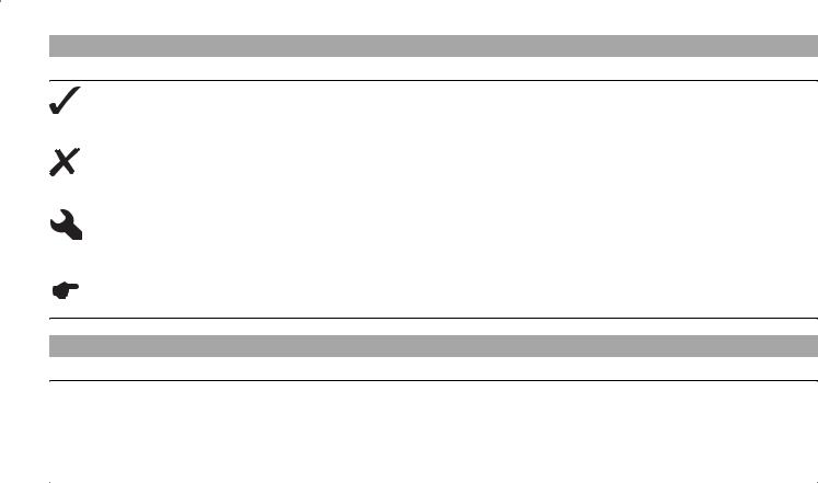
Indicates an expected reaction (e.g. of a work step or a function).
Indicates an unexpected reaction (e.g. of a work step or a function).
All work marked with this symbol requires specialist knowledge and technical understanding. In the interest of your own safety, have these jobs done in an authorized KTM workshop! There, your motorcycle will be serviced optimally by specially trained experts using the specialist tools required.
Identifies a page reference (more information is provided on the specified page).
Formats used
The typographical and other formats used are explained in the following.
Specific name |
Identifies a specific name. |
Name® |
Identifies a protected name. |
Brand™ |
Identifies a brand in merchandise traffic. |
|
|
IMPORTANT NOTES |
5 |
Use definition
KTM sport motorcycles are designed and built to withstand the normal stresses and strains of competitive use. The motorcycles comply with currently valid regulations and categories of the top international motorsport organizations.
Info
The motorcycle must be used only on secluded property remote from public road traffic.
Maintenance
A prerequisite for perfect operation and prevention of wear is that the engine and chassis maintenance and adjustment work described in the owner's manual are properly carried out. Poor adjustment and tuning of the engine and chassis can lead to damage and breakage of components.
Using the motorcycle in extreme conditions such as very muddy or wet terrain can lead to above-average wear of components such as the transmission train or the brakes. For this reason, it may be necessary to service or replace worn parts before the limit specified in the greasing and service table is reached.
Pay careful attention to the prescribed running-in period, inspection and maintenance intervals. If you observe these exactly, you will ensure a much longer service life for your motorcycle.
Warranty
The maintenance work prescribed in the greasing and service table must be carried out in an authorized KTM workshop and confirmed in the customer's service record, since otherwise no warranty claims will be recognized. No warranty claims can be considered for damage resulting from manipulations and alterations to the motorcycle.
Fuel, oils, etc.
You should use the fuels, oils and greases according to specifications as listed in the owner's manual.
Spare parts, accessories
For your own safety, use only spare parts and accessories approved by KTM. KTM accepts no liability for other products and any resulting damage or loss.
Transport
Note
Danger of damage Danger of damage by the vehicle running away or falling over.
Always place the vehicle on a firm and even surface.
Note
Fire hazard Some components (engine, radiator and exhaust system) get very hot when the engine is running.
Do not place the vehicle where there are flammable or explosive substances.
switch off engine.
Turn the handle of the fuel tap to the OFF position.
Use straps or other suitable devices to secure the motorcycle against accidents or falling over.
Environment
Offroad motorcycling is a wonderful sport and we naturally hope that you will be able to enjoy it to the fullest. However, it is a potential problem for the environment and can lead to conflicts with other persons. But if you use your motorcycle responsibly, you can ensure that such problems and conflicts do not have to occur. To protect the future of motorcycle sport, make sure that you use your motorcycle legally, display environmental consciousness, and respect the rights of others.
Warning notes
In your own interest, read the specified warning notes.
Info
Various warning labels are attached to your vehicle. Do not remove any warning labels. If they are missing, you or others may not recognize dangers and may therefore be injured.
IMPORTANT NOTES |
6 |
Grades of risks
Danger
Danger that leads immediately and certainly to severe and permanent injury or death.
Warning
Danger that will probably lead to severe and permanent injury or death.
Note
Danger of serious damage to machine or material.
Warning
Risk of environmental damage.
OWNER'S MANUAL
Read this owner's manual carefully and completely before making your first trip. It contains a lot of information and tips to help you operate and handle your motorcycle. Only then will you find out how to customize the motorcycle ideally for your own use and how you can protect yourself from injury. The owner's manual also contains important information on servicing the motorcycle.
The owner's manual is an important component of the motorcycle and should be handed over to the new owner if the vehicle is sold.
|
VIEW OF VEHICLE |
7 |
|
|
|
|
|
|
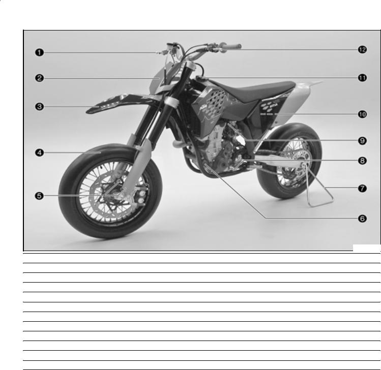
View of vehicle, front left side |
|
|
|
|
|
|
500182-10
1Hand brake lever
2Start number plate
3Front fender
4Front wheel
5Fork part number
6Oil filter cover
7Plug-in stand
8Shift lever
9Choke button
10Air filter
11Filler cap
12Clutch lever
|
VIEW OF VEHICLE |
8 |
|
|
|
|
|
|
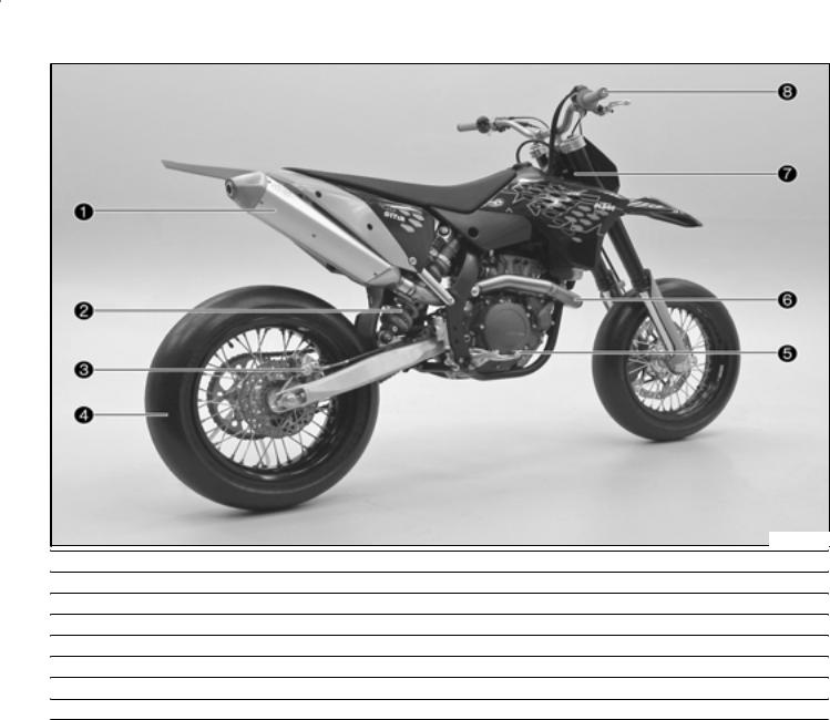
View of vehicle, rear right side |
|
|
|
|
|
|
500183-10
1Main silencer
2Shock absorber
3Brake caliper of rear wheel brake
4Rear wheel
5Foot brake pedal
6Manifold
7Chassis number/type label
8Throttle grip
LOCATION OF SERIAL NUMBERS |
9 |
Chassis number
The chassis number is stamped on the steering head on the right.
400193-10
Type label
The type label is fixed to the front of the steering head.
400284-10
Engine number
The engine number is stamped on the left side of the engine under the engine sprocket.
400194-10
Fork part number
The fork part number is stamped on the inner side of the fork stub.
500175-10
Shock absorber part number
The shock absorber part number is stamped on the top of the shock absorber above the adjusting ring on the engine side.
500083-10
OPERATING ELEMENTS |
10 |
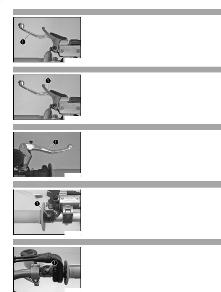
Clutch lever
The clutch lever is fitted on the left side of the handlebar.
The clutch is hydraulically operated and self-adjusting.
400195-10
Hot start lever
The hot start lever is fitted on the left side of the handlebar.
If you pull the hot start lever to the handlebar during the start procedure, a bore is opened in the carburetor through which the engine can draw in extra air. This gives a leaner fuel-air mixture, which is needed for a hot start.
Possible states
•Hot start function activated Hot start lever is pulled out to the stop.
•Hot start function deactivated Hot start lever is pushed back to the stop.
400195-12
Hand brake lever
The hand brake lever is located on the right side of the handlebar and operates the front wheel brake.
500176-10
Short circuit button
The short circuit button is fitted on the left side of the handlebar.
Possible states
•Short circuit button  in basic position In this position, the ignition circuit is closed, and the engine can be started.
•Short circuit button  pressed In this position, the ignition circuit is interrupted, a running engine stops, and a non-running engine will not start.
400197-10
Electric starter button
The electric starter button is fitted on the right side of the handlebar.
Possible states
•Electric starter button  in basic position
•Electric starter button  pressed In this position, the electric starter is actuated.
500177-10
OPERATING ELEMENTS |
11 |
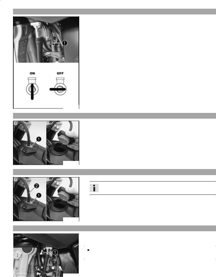
Fuel tap
With the tap handle on the fuel tap, you can open or close the supply of fuel to the carburetor.
Possible states
•Fuel supply closed OFF No fuel can flow from the tank to the carburetor.
•Fuel supply open ON Fuel can flow from the tank to the carburetor. The fuel tank empties completely.
500178-10
Opening filler cap
Press release button , turn filler cap counterclockwise and lift it free.
400199-10
Closing filler cap
Replace the filler cap and turn clockwise until the release button locks in place.
Info
Run the fuel tank breather hose without kinks.
400199-11
Choke
|
|
The choke is fitted on the left side of the carburetor. |
|||
|
|
Activating the choke function frees an opening through which the engine can draw ex- |
|||
|
|
tra fuel. This gives a richer fuel-air mixture, which is needed for a cold start. |
|||
|
|
|
|
|
|
|
|
|
|
|
Info |
|
|
|
|
|
|
|
|
|
|
|
If the engine is warm, the choke function must be deactivated. |
|
|
|
|||
|
|
Possible states |
|||
|
|
• Choke function activated The choke lever is pulled out to the stop. |
|||
500179-10 |
|
• Choke function activated The choke lever is pushed in to the stop. |
|||
|
|
|
|
|
|
|
|
|
|
|
|
OPERATING ELEMENTS |
12 |
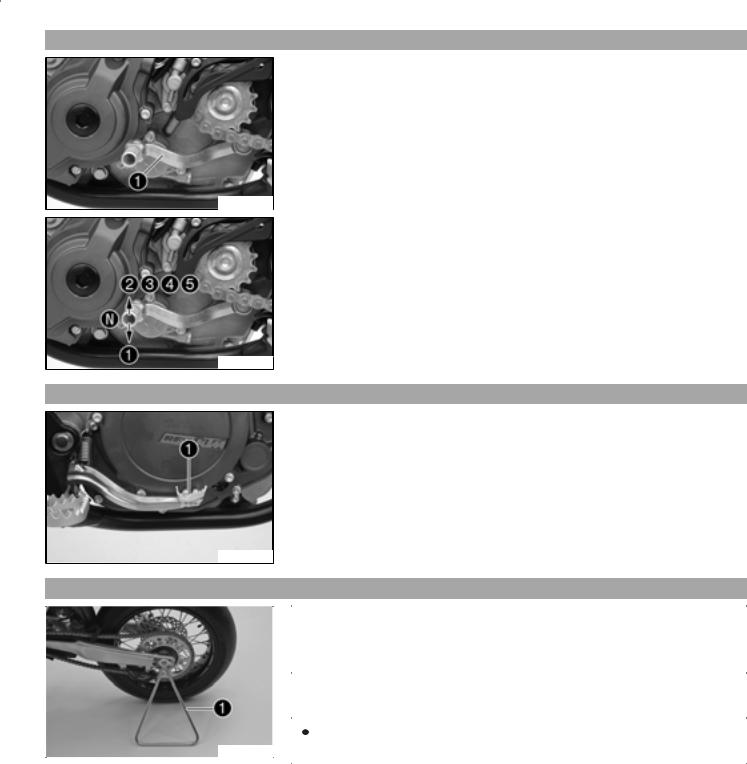
Shift lever
The shift lever is mounted on the left side of the engine.
400204-12
The gear positions can be seen in the photograph.
The neutral or idle position is between the first and second gears.
400204-11
Foot brake pedal
The foot brake pedal is located in front of the right footrest and operates the rear wheel brake.
400205-10
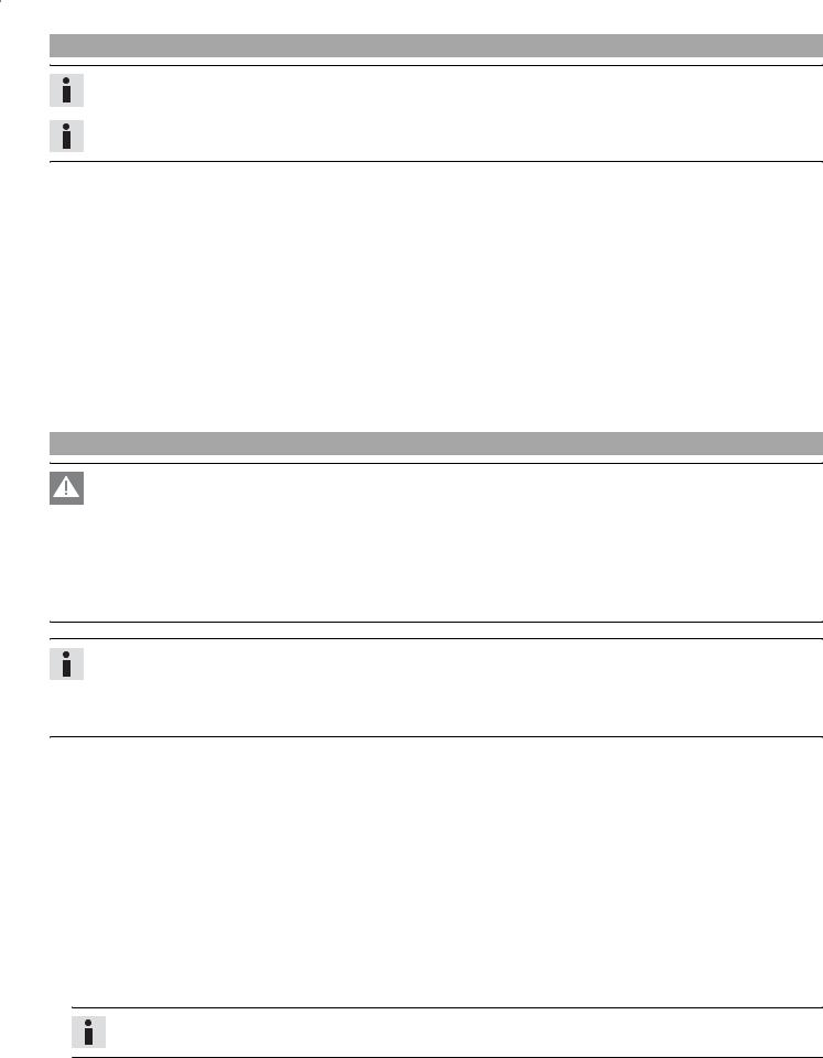
Plug-in stand
|
|
Note |
|||
|
|
Danger of damage Danger of damage by the vehicle running away or falling over. |
|||
|
|
Always place the vehicle on a firm and even surface. |
|||
|
|
|
|||
|
|
To stand the motorcycle, plug the plug-in stand into the left side of the wheel spin- |
|||
|
|
dle. |
|||
|
|
|
|
|
|
|
|
|
|
|
Info |
|
|
|
|
|
|
500180-10 |
|
|
|
|
Before riding, remove the plug-in stand. |
|
|
|
|
|
|
|
|
|
|
|
|
GENERAL TIPS AND HINTS ON PUTTING INTO OPERATION |
13 |
Advice on first use
Danger
Danger of accidents Danger from inadequate traffic experience.
Do not use the vehicle if you are inexperienced or if you have consumed alcohol or drugs.
Warning
Risk of injury Risk of injury by missing/inadequate protective clothing.
Wear protective clothing (helmet, boots, gloves, pants and jacket with protectors) every time you ride the vehicle.
Warning
Danger of accidents Critical riding behavior due to inappropriate riding.
Adapt your riding speed to the road conditoins and your riding ability.
Warning
Danger of accidents Accident risk caused by presence of a passenger.
Your vehicle is not designed to carry passengers. Do not ride with a passenger.
Warning
Danger of accidents Brake system failure.
If the foot brake pedal is not released, the brake linings drag permanently. The rear brake can fail due to overheating. Take your foot off the foot brake pedal if you do not want to brake.
Warning
Danger of accidents Unstable riding behavior.
Do not exceed the maximum permitted weight and axle loads.
Warning
Risk of misappropriation Usage by unauthorized persons.
Never leave the vehicle while the engine is running. Secure the vehicle against use by unauthorized persons.
Info
When using your motorcycle, remember that others may feel disturbed by excessive noise.
Make sure that the pre-delivery inspection work has been carried out by an authorized KTM workshop. You receive a delivery certificate and the service record at vehicle handover.
Before your first trip, read the entire operating instructions carefully.
Get to know the operating elements.
adjust the basic position of clutch lever. ( P. 59)
adjust the basic position of handbrake lever. ( P. 39)
Adjust the basic position of the footbrake lever. ( P. 43)
Get used to handling the motorcycle on a suitable piece of land before making a longer trip.
Info
Your motorcycle is not licensed for use on public roads.
Try also to ride as slowly as possible and in a standing position to get a better feeling for the vehicle.
Do not make any trips that over-stress your ability and experience.
Hold the handlebar firmly with both hands and keep your feet on the footrests when riding.
Do not make any changes to the motorcycle, and use only KTM approved parts.
Do not carry any baggage.
Info
Motorcycles react sensitively to any changes of weight distribution.
Do not exceed the overall maximum permitted weight and the axle loads. Specification
Maximum permissible overall weight |
335 kg (738.54 lb.) |
|
|
Maximum permissible front axle load |
145 kg (319.67 lb.) |
|
|
Maximum permissible rear axle load |
190 kg (418.87 lb.) |
|
|
Run the engine in.
GENERAL TIPS AND HINTS ON PUTTING INTO OPERATION |
14 |
Running in the engine
During the running-in phase, do not exceed the specified engine speed and engine performance. Specification
|
Maximum engine speed |
|
|
|
|
|
During the first 3 service hours |
7000 rpm |
|
|
|
|
Maximum engine performance during the running-in period |
|
|
|
|
|
During the first 3 service hours |
50 % |
|
|
|
|
During the next 12 service hours |
75 % |
|
|
|
Avoid fully opening the throttle! |
|
|
RIDING INSTRUCTIONS |
15 |
Checks before putting into operation
Info
Make sure that the motorcycle is in a perfect technical condition before use.
Info
In the interests of riding safety, make a habit of making a general check before you ride.
Check the engine oil level. ( P. 62)
Check the chain tension. ( P. 34)
Check the chain dirt accumulation. ( P. 34)
Check the tire condition. ( P. 49)
Checking the tire air pressure. ( P. 49)
Check the front brake brake fluid level. ( P. 39)
Check the rear brake fluid level. ( P. 43)
Check the front brake linings. ( P. 40)
Check the rear brake linings. ( P. 44)
Check brake system function.
Check the coolant level. ( P. 55)
Check that all operating elements are correctly adjusted and free to move.
Starting
Danger
Danger of poisoning Exhaust gases are poisonous and can result in unconsciousness and/or death.
When running the engine, always make sure there is sufficient ventilation, and do not start or run the engine in a closed space.
Note
Engine failure High engine speeds in cold engines have a negative effect on the service life of the engine.
Always warm up the engine at low engine speeds.
Info
If the motorcycle is unwilling to start, the cause can be old fuel in the float chamber. The flammable elements of the fuel evaporate after a long time of standing.
If the float chamber is filled with fresh fuel, the engine starts immediately.
Press the starter for a maximum of 5 seconds. Wait for a least 5 seconds until trying again.
Conditions
Motorcycle standing still: 1 week
Empty the carburetor float chamber. ( P. 62)
Turn the handle of the fuel tap to the ON position. (Figure 500178-10  P. 11)
  Fuel can flow from the tank to the carburetor.
Remove the motorcycle from the stand.
Shift gear to neutral.
Conditions
Engine cold
Pull choke lever out as far as possible.
Conditions
Engine warm
Pull the hot start lever out to the stop.
Press the electric starter button. 
Info
Don't open the throttle.
Conditions
Engine hot and running
Push back the hot start lever to the stop with the engine running.
RIDING INSTRUCTIONS |
16 |
Starting up
Pull the clutch lever, engage 1st gear, release the clutch lever slowly and simultaneously open the throttle carefully.
Shifting, riding
Warning
Danger of accidents If you change down at high engine speed, the rear wheel can lock up.
Do not change into a low gear at high engine speed. The engine races and the rear wheel can block.
Info
If you hear unusual noises while riding, stop immediately, switch off the engine and contact an authorized KTM workshop. First gear is used for starting off or for steep inclines.
When conditions allow (incline, road situation, etc.), you can shift into a higher gear. To do so, release the throttle while simultaneously pulling the clutch lever, shift into the next gear, release the clutch and open the throttle.
If the choke function was activated, deactivate it after the engine has warmed up.
When you reach maximum speed after fully opening the throttle, turn back the throttle to about 3/4 of its range; the speed hardly drops, but the fuel consumption falls considerably.
Always open the throttle only as much as the engine can handle abrupt throttle opening increases fuel consumption.
To shift down, brake if necessary and close the throttle at the same time.
Pull the clutch lever and shift into a lower gear, release the clutch lever slowly and open the throttle or shift again.
Switch off the engine if you expect to be standing for a long time. Specification

 2 min
2 min
Avoid frequent and longer slipping of the clutch. This heats the engine oil, the engine and the cooling system.
Ride with a lower engine speed instead of with a high engine speed and a slipping clutch.
Braking
Warning
Danger of accidents If you brake too hard, the wheels can lock.
Adapt your braking to the traffic situation and the road conditions.
Warning
Danger of accidents Reduced braking caused by spongy pressure point of front or rear brake.
Have the brake system checked in an authorized KTM workshop, and do not ride any further.
Warning
Danger of accidents Reduced braking due to wet or dirty brakes.
Clean or dry dirty or wet brakes by riding and braking gently.
On sandy, wet or slippery surfaces, use the rear brake.
Braking should always be completed before you go into a bend. Change down to a lower gear appropriate to your road speed.
On long downhill stretches, use the braking effect of the engine. Change down one or two gears, but do not overstress the engine. In this way, you have to brake far less and the brakes do not overheat.
Stopping, parking
Warning
Danger of burns Some vehicle components get very hot when the machine is driven.
Do not touch hot components such as exhaust system, radiator, engine, shock absorber and brakes. Allow these components to cool down before starting work on them.
Note
Danger of damage Danger of damage by the vehicle running away or falling over.
Always place the vehicle on a firm and even surface.
RIDING INSTRUCTIONS |
17 |
Note
Fire hazard Some components (engine, radiator and exhaust system) get very hot when the engine is running.
Do not place the vehicle where there are flammable or explosive substances.
Brake the motorcycle.
Shift gear to neutral.
Press the short circuit button  when the engine is idling until the engine stops.
Turn the handle of the fuel tap to the OFF position. (Figure 500178-10  P. 11)
Stand the motorcycle on a hard surface.
Refueling
Danger
Fire hazard Fuel can easily catch fire.
Never fill up the vehicle near open flames or burning cigarettes, and always switch off the engine first. Be careful that no fuel is spilt, especially on hot vehicle components. Clean up spilt fuel immediately.
Fuel in the fuel tank expands when warm and can escape if the tank is overfilled. See specifications on filling up with fuel.
Warning
Danger of poisoning Fuel is poisonous and a health hazard.
Avoid contact between fuel and skin, eyes and clothing. Do not inhale fuel vapors. If fuel gets into your eyes, rinse immediately with water and contact a doctor. Wash affected skin areas immediately with soap and water. If fuel is swallowed, contact a doctor immediately. Change clothing that has come into contact with fuel.
Warning
Environmental hazard Improper handling of fuel is a danger to the environment.
Do not allow fuel to get into the ground water, the ground, or the sewage system.
Open the filler cap. ( P. 11)
Fill the fuel tank with fuel up to measurement . Specification
|
Measurement of |
|
35 mm (1.38 in) |
|
A |
|
|
|
|
|
|
|
||
Tank capacity |
8.2 l |
Super unleaded (ROZ 95 / RON 95 / |
||
|
||||
|
|
(2.17 US gal) |
PON 91) ( P. 82) |
|
|
|
|
|
Close the filler cap. ( P. 11)
400382-10
GREASING AND SERVICE TABLE |
18 |
Important maintenance work to be carried out by an authorized KTM workshop.
|
|
|
|
|
|
|
S3N |
S10A |
S30A |
|
|
|
|
|
|||||
Engine |
Change the engine oil and oil filter, and clean the oil screen. ( P. 63) |
• |
• |
|
|||||
|
|
|
|
|
|
|
|
|
|
|
Replace spark plug. |
|
|
|
|
|
|
|
• |
|
|
|
|
|
|
|
|
||
|
Check and adjust valve clearance. |
|
|
|
• |
• |
|
||
|
|
|
|
|
|
||||
|
Check engine mounting screws for tightness. |
|
• |
• |
|
||||
|
|
|
|
|
|||||
|
Clean spark plug connectors and check for tightness. |
• |
• |
|
|||||
|
|
|
|
|
|
|
|||
|
Check screw of shift lever for tightness. |
|
|
• |
• |
|
|||
|
|
|
|
|
|||||
Carburetor |
Check carburetor connection boots for cracks and leakage. |
|
• |
|
|||||
|
|
|
|
|
|||||
|
Check vent hoses for damage and routing without sharp bends. |
• |
• |
|
|||||
|
|
|
|
|
|
|
|
|
|
|
Check idle. |
|
|
|
|
|
• |
• |
|
|
|
|
|
|
|
|
|||
Attachments |
Check the cooling system for leakage. |
|
|
• |
• |
|
|||
|
|
|
|
|
|
||||
|
Check the antifreeze and coolant level. ( |
P. 55) |
• |
• |
|
||||
|
|
|
|
|
|||||
|
Check the exhaust system for leakage and looseness. |
|
• |
|
|||||
|
|
|
|
|
|||||
|
Check Bowden cables for damage, smooth operation and routing without sharp |
• |
• |
|
|||||
|
bends. |
|
|
|
|
|
|
||
|
|
|
|
|
|
|
|
|
|
|
|
|
|
|
|
||||
|
Check the fluid level of the hydraulic clutch. ( |
P. 60) |
• |
• |
|
||||
|
|
|
|
|
|
|
|
||
|
Clean the air filter. ( P. 59) |
|
|
|
• |
• |
|
||
|
|
|
|
|
|||||
|
Check cables for damage and routing without sharp bends. |
|
• |
|
|||||
|
|
|
|
|
|
|
|
||
Brakes |
Check the front brake linings. ( |
P. 40) |
|
|
• |
• |
|
||
|
|
|
|
|
|
|
|||
|
Check the rear brake linings. ( P. 44) |
|
|
• |
• |
|
|||
|
|
|
|
|
|
|
|
|
|
|
Check the brake discs. ( |
P. 38) |
|
|
|
• |
• |
|
|
|
|
|
|
|
|
||||
|
Check the front brake brake fluid level. ( |
P. 39) |
• |
• |
|
||||
|
|
|
|
|
|
|
|||
|
Check the rear brake fluid level. ( |
P. 43) |
|
• |
• |
|
|||
|
|
|
|
|
|
||||
|
Check brake lines for damage and leakage. |
|
• |
• |
|
||||
|
|
|
|
|
|
||||
|
Check the free play of the hand brake lever. ( |
P. 39) |
• |
• |
|
||||
|
|
|
|
|
|
||||
|
Check the free play of the foot brake lever. ( |
P. 43) |
• |
• |
|
||||
|
|
|
|
|
|
|
|
||
|
Check brake system function. |
|
|
|
• |
• |
|
||
|
|
|
|
|
|||||
|
Check screws and guide bolts of brake system for tightness. |
• |
• |
|
|||||
|
|
|
|
|
|||||
Chassis |
Check shock absorber and fork for leakage and functioning. |
• |
• |
|
|||||
|
|
|
|
|
|
|
|
||
|
Clean dust boots of fork legs. ( |
P. 26) |
|
|
|
• |
|
||
|
|
|
|
|
|
|
|
|
|
|
Bleed fork legs. ( |
P. 26) |
|
|
|
|
|
• |
|
|
|
|
|
|
|
|
|
|
|
|
Check swingarm bearing. |
|
|
|
|
|
• |
|
|
|
|
|
|
|
|
||||
|
Check play of steering head bearing. ( |
P. 27) |
• |
• |
|
||||
|
|
|
|
|
|
|
|||
|
Check all screws to see if they are tight. |
|
|
• |
• |
|
|||
|
|
|
|
|
|
|
|
||
Wheels |
Check the spoke tension. ( |
P. 50) |
|
|
• |
• |
|
||
|
|
|
|
|
|
|
|
|
|
|
Check rim run-out. |
|
|
|
|
|
• |
• |
|
|
|
|
|
|
|
|
|
||
|
Check the tire condition. ( |
P. 49) |
|
|
• |
• |
|
||
|
|
|
|
|
|
|
|||
|
Checking the tire air pressure. ( |
P. 49) |
|
• |
• |
|
|||
|
|
|
|
|
|
|
|
|
|
|
Check the chain wear. ( |
P. 35) |
|
|
|
• |
• |
|
|
|
|
|
|
|
|
|
|
||
|
Check the chain tension. ( |
P. 34) |
|
|
• |
• |
|
||
|
|
|
|
|
|
|
|
|
|
|
Clean the chain. ( |
P. 34) |
|
|
|
• |
• |
|
|
|
|
|
|
|
|
|
|
||
|
Check wheel bearing for play. |
|
|
|
• |
• |
|
||
|
|
|
|
|
|||||
|
Clean and grease adjusting screws of chain adjuster. |
• |
• |
|
|||||
|
|
|
|
|
|
|
|
|
|
S3N: After 3 service hours - corresponds to about 21 liters of fuel
S10A: Every 10 service hours - corresponds to about 70 liters of fuel / after every race
S30A: Every 30 service hours - corresponds to about 210 liters of fuel
GREASING AND SERVICE TABLE |
19 |
Important maintenance work to be carried out by an authorized KTM workshop. (as additional order)
|
S10A |
S20N |
S40N |
J1A |
J2A |
|
|
|
|
|
|
Carry out a complete fork service. |
|
|
|
• |
|
|
|
|
|
|
|
Carry out a complete shock absorber service. |
|
|
|
|
• |
|
|
|
|
|
|
Grease the steering head bearing. ( P. 31) |
|
|
|
• |
|
|
|
|
|
|
|
Clean and adjust carburetor. |
|
|
|
• |
|
|
|
|
|
|
|
Treat electric contacts with contact spray. |
|
|
|
• |
|
|
|
|
|
|
|
Change hydraulic clutch fluid. |
|
|
|
• |
|
|
|
|
|
|
|
Change brake fluid. |
|
|
|
• |
|
|
|
|
|
|
|
Check wear of clutch discs. |
|
• |
|
|
|
|
|
|
|
|
|
Check long clutch springs. |
|
• |
|
|
|
|
|
|
|
|
|
Check clutch slave cylinder for dents. |
|
• |
|
|
|
|
|
|
|
|
|
Check outer clutch hub for dents. |
|
• |
|
|
|
|
|
|
|
|
|
Check cylinder wear and change pistons. |
|
|
• |
|
|
|
|
|
|
|
|
Check camshaft wear. (visual check) |
|
|
• |
|
|
|
|
|
|
|
|
Check wear of valve spring seat. |
|
|
• |
|
|
|
|
|
|
|
|
Check wear of valve guides. |
|
|
• |
|
|
|
|
|
|
|
|
Change valves. |
|
|
• |
|
|
|
|
|
|
|
|
Change valve springs. |
|
|
• |
|
|
|
|
|
|
|
|
Check the timing-chain tensioner function. |
|
|
• |
|
|
|
|
|
|
|
|
Check crankshaft and crankshaft journal for run-out. |
|
|
• |
|
|
|
|
|
|
|
|
Change conrod bearing. |
|
|
• |
|
|
|
|
|
|
|
|
Check piston pin bearing. |
|
|
• |
|
|
|
|
|
|
|
|
Change the crankshaft main bearing. |
|
|
• |
|
|
|
|
|
|
|
|
Check wear of all transmission components including shafts and bearings. |
|
|
• |
|
|
|
|
|
|
|
|
Check the spring length of the oil pressure regulator valve. |
|
|
• |
|
|
|
|
|
|
|
|
Change glass fiber yarn filling of main silencer. ( P. 58) |
• |
|
|
|
|
|
|
|
|
|
|
Replace foot brake cylinder seals. |
|
• |
|
|
|
|
|
|
|
|
|
Check carburetor components. |
|
|
• |
|
|
|
|
|
|
|
|
S10A: Every 10 service hours - corresponds to about 70 liters of fuel / after every race |
|
|
|
|
|
S20N: After 20 service hours - corresponds to about 140 liters of fuel |
|
|
|
|
|
S40N: After 40 service hours - corresponds to about 280 liters of fuel |
|
|
|
|
|
J1A: annually |
|
|
|
|
|
J2A: every 2 years |
|
|
|
|
|
Important checks and maintenance work to be carried out by the rider.
|
|
|
|
NB1A |
|
|
|
||
Check the engine oil level. ( |
P. 62) |
• |
||
|
|
|||
Check the front brake brake fluid level. ( P. 39) |
• |
|||
|
|
|
||
Check the rear brake fluid level. ( |
P. 43) |
• |
||
|
|
|
||
Check the front brake linings. ( |
P. 40) |
• |
||
|
|
|||
Check the rear brake linings. ( P. 44) |
• |
|||
|
|
|
||
Check and adjust Bowden cables. |
|
• |
||
|
|
|
|
|
Bleed fork legs. ( |
P. 26) |
|
|
• |
|
|
|
||
Clean dust boots of fork legs. ( |
P. 26) |
• |
||
|
|
|
|
|
Clean the chain. ( |
P. 34) |
|
|
• |
|
|
|
||
Check the chain tension. ( |
P. 34) |
• |
||
|
|
|
||
Check the chain wear. ( P. 35) |
|
• |
||
|
|
|||
Check the rear sprocket / engine sprocket for wear. ( P. 35) |
• |
|||
|
|
|
||
Clean the air filter. ( P. 59) |
|
• |
||
|
|
|
||
Checking the tire air pressure. ( |
P. 49) |
• |
||
|
|
|
||
Check the tire condition. ( |
P. 49) |
• |
||
|
|
|
|
|
|
GREASING AND SERVICE TABLE |
20 |
|
|
|
|
|
|
|
NB1A |
|
|
|
|
|
|
Check the coolant level. ( P. 55) |
• |
|
|
|
|
|
|
Empty the carburetor float chamber. ( P. 62) |
• |
|
|
|
|
|
|
Check that all operating elements for smooth operation. |
• |
|
|
|
|
|
|
Check braking. |
• |
|
|
|
|
|
|
Check all screws, nuts and hose clamps regularly for tightness. |
• |
|
|
|
|
|
|
NB1A: Depending on conditions of use according to requirements. |
|
|
MAINTENANCE WORK ON CHASSIS AND ENGINE |
21 |
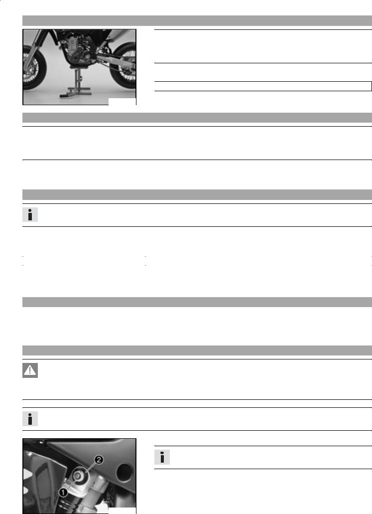
Jacking up the motorcycle
Note
Danger of damage Danger of damage by the vehicle running away or falling over.
Always place the vehicle on a firm and even surface.
Jack up the motorcycle underneath the engine. The wheels must no longer touch the ground.

 Work stand (59229055000)
Secure the motorcycle against falling over.
500181-01
Removing the motorcycle from the work stand
Note
Danger of damage Danger of damage by the vehicle running away or falling over.
Always place the vehicle on a firm and even surface.
Remove the motorcycle from the work stand.
Remove the work stand.
Checking the basic chassis setting with the rider's weight
Info
When adjusting the basic chassis setting, first adjust the shock absorber and then the fork.
For optimal motorcycle riding characteristics and to avoid damage to forks, shock absorbers, swing arm and frame, the basic settings of the suspension components must match your body weight.
As delivered, KTM motorcycles are adjusted for a standard rider weight (with full protective clothing).
Standard rider weight |
75… 85 kg (165.34… 187.39 lb.) |
|
|
If your weight is above or below the standard range, you have to adjust the basic setting of the suspension components accordingly. Small weight differences can be compensated by adjusting the spring preload, but in the case of large weight differences, the springs must be replaced.
Compression damping of shock absorber
The shock absorber can regulate compression damping in lowand high-speed range separately (Dual Compression Control).
The term low and high speed refers to the movement of the shock absorber during compression and not the riding speed of the motorcycle.
The lowand high-speed technology works non-specifically.
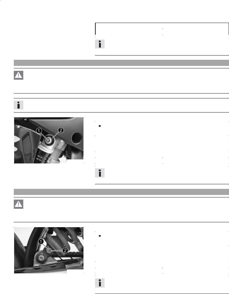
Adjusting high-speed compression damping of the shock absorber
Danger
Danger of accidents The shock absorber is under high pressure.
The shock absorber is filled with highly compressed nitrogen, so never dismantle the shock absorber or carry out any maintenance on it yourself.
Info
The high-speed setting can be seen during the fast compression of the shock absorber.
Turn the adjusting screw clockwise with a ring wrench until it stops.
Info
Do not loosen nut !
500184-10
MAINTENANCE WORK ON CHASSIS AND ENGINE |
22 |
Turn back counterclockwise the number of turns corresponding to the shock absorber type.
Specification
Compression damping, high-speed
Standard |
1.5 turns |
|
|
|
|
Info
Turn clockwise to increase damping, turn counterclockwise to reduce suspension damping.
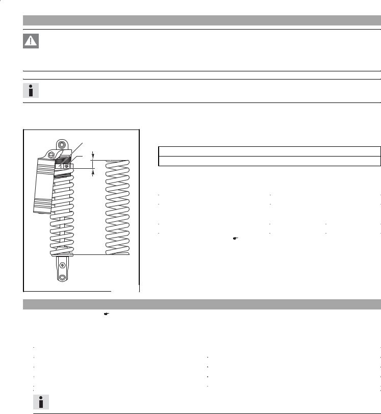
Adjusting the low-speed compression damping of the shock absorber
Danger
Danger of accidents The shock absorber is under high pressure.
The shock absorber is filled with highly compressed nitrogen, so never dismantle the shock absorber or carry out any maintenance on it yourself.
Info
The low-speed setting can be seen during the slow to normal compression of the shock absorber.
|
Turn the adjusting screw clockwise with a screwdriver until it stops. |
|||||
|
|
|
|
|
|
|
|
|
|
|
|
Info |
|
|
|
|
|
|
|
|
|
|
|
|
|
Do not loosen nut ! |
|
|
|
|
|
|||
|
Turn back counterclockwise the number of clicks corresponding to the shock ab- |
|||||
|
|
sorber type. |
|
|||
|
|
Specification |
|
|||
|
|
|
|
|||
|
|
Compression damping, low-speed |
|
|||
|
|
|
|
|
|
|
500184-11 |
|
|
|
Standard |
10 clicks |
|
|
|
|
|
|
|
|
|
|
|
|
|
|
|
Info
Turn clockwise to increase damping, turn counterclockwise to reduce suspension damping.
Adjusting rebound damping of the shock absorber
Danger
Danger of accidents The shock absorber is under high pressure.
The shock absorber is filled with highly compressed nitrogen, so never dismantle the shock absorber or carry out any maintenance on it yourself.
|
Turn the adjusting screw clockwise until it stops. |
|||||
|
|
|
|
|
|
|
|
|
|
|
|
Info |
|
|
|
|
|
|
|
|
|
|
|
|
|
Do not loosen nut ! |
|
|
|
|
|
|||
|
Turn back counterclockwise the number of clicks corresponding to the shock ab- |
|||||
|
|
sorber type. |
|
|||
|
|
Specification |
|
|||
|
|
|
|
|||
|
|
Rebound damping |
|
|||
|
|
|
|
|
|
|
500185-10 |
|
|
|
Standard |
20 clicks |
|
|
|
|
|
|
|
|
Info
Turn clockwise to increase damping, turn counterclockwise to reduce suspension damping.

MAINTENANCE WORK ON CHASSIS AND ENGINE |
23 |
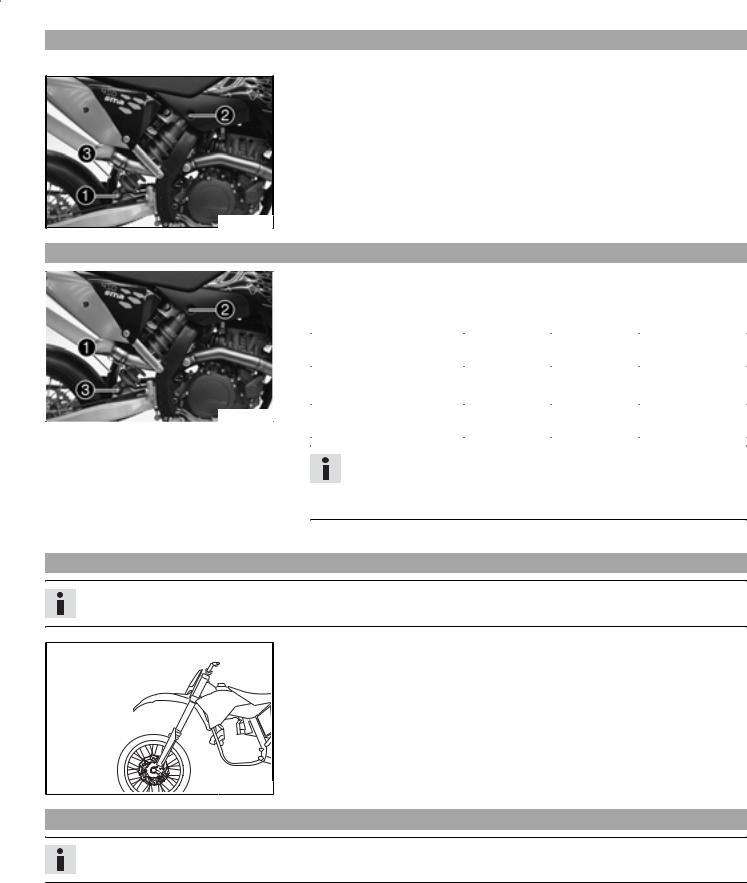
Measuring rear wheel sag unloaded
Jack up the motorcycle. ( P. 21)
0A |
400389-10 |
Measure the distance as vertical as possible between the rear axle and a fixed point, for example, a mark on the side cover.
Make a note of the value as measurement .
Remove the motorcycle from the work stand. ( P. 21)
Checking static sag of the shock absorber
0A |
0B |
400383-10 |
Measure distance of rear wheel unloaded. ( P. 23)
Ask someone to help you by holding the motorcycle upright.
Measure the distance between the rear axle and the fixed point again.
Make a note of the value as measurement .
Info
The static sag is the difference between measurements and .
Check the static sag.
Static sag |
15… 20 mm (0.59… 0.79 in) |
|
|
»If the static sag is less or more than the specified value:
Adjust the spring preload of the shock absorber. ( P. 24)
Check the riding sag of the shock absorber.
0A |
C |
400384-10 |
Measure distance of rear wheel unloaded. ( P. 23)
With another person holding the motorcycle, sit on the saddle with full protective clothing in a normal sitting position (feet on footrests) and bounce up and down a few times until the rear suspension levels out.
The other person now has to measure the distance between the rear axle and a fixed point.
Make a note of the value as measurement .
Info
The riding sag is the difference between measurements and .
Check the riding sag.
Riding sag |
80… 90 mm (3.15… 3.54 in) |
|
|
»If the riding sag differs from the specified measurement:Adjust the riding sag. ( P. 24)
MAINTENANCE WORK ON CHASSIS AND ENGINE |
24 |
Adjusting spring preload of the shock absorber x
Danger
Danger of accidents The shock absorber is under high pressure.
The shock absorber is filled with highly compressed nitrogen, so never dismantle the shock absorber or carry out any maintenance on it yourself.
Info
Before changing the spring preload, make a note of the present setting, e.g., by measuring the length of the spring.
2 |
1 |
A |
400216-10 |
Remove shock absorber. ( P. 25)
After removing the shock absorber, clean it thoroughly.
Loosen screw .
Turn adjusting ring until the spring is no longer under tension. Combination wrench (50329080000)
Hook wrench (T106S)
Measure the overall spring length when not under tension.
Tighten the spring by turning adjusting ring to measurement . Specification
|
Spring preload |
11 mm (0.43 in) |
|
|
|
|
|
|
Tighten screw . |
|
|
|
Specification |
|
|
|
|
|
|
|
Screw, shock absorber adjusting ring |
M6 |
5 Nm (3.69 lbf ft) |
|
|
|
|
|
Installing shock absorber. ( P. 25) |
|
|
Adjusting riding sag x
|
Remove shock absorber. ( P. 25) |
After removing the shock absorber, clean it thoroughly. |
|
|
Choose and fit a suitable spring. |
Specification |
|
Spring rate |
|
|
|
Weight of rider: 65… 75 kg (143.3… 165.34 lb.) |
76 N/mm (433.97 lb/in) |
|
|
Weight of rider: 75… 85 kg (165.34… 187.39 lb.) |
80 N/mm (456.81 lb/in) |
|
|
Weight of rider: 85… 95 kg (187.39… 209.44 lb.) |
84 N/mm (479.65 lb/in) |
|
|
|
|
Info
The spring rate is shown on the outside of the spring.
Installing shock absorber. ( P. 25)
Check the static sag of the shock absorber. ( P. 23)
Adjust the rebound damping of the shock absorber. ( P. 22)
MAINTENANCE WORK ON CHASSIS AND ENGINE |
25 |
Removing the shock absorber x
Jack up the motorcycle. ( P. 21)
Remove screw and lower the rear wheel with the swing arm as far as possible without blocking the rear wheel. Fix the rear wheel in this position.
Remove screw , push splash protector to the side, and remove the shock absorber.
500186-10
Installing shock absorber x
|
Check parts for damage and wear. Replace damaged or worn parts. |
||||
|
Push splash protector to the side and position the shock absorber. Mount and |
||||
|
|
tighten screw . |
|
|
|
|
|
Specification |
|
|
|
|
|
|
|
|
|
|
|
Screw, top shock absorber |
M12 |
80 Nm |
Loctite® 243™ |
|
|
|
|
(59.01 lbf ft) |
|
|
|
|
|
|
|
|
Mount and tighten screw . |
|
|
|
|
|
|
Specification |
|
|
|
|
|
|
|
|
|
500186-11 |
|
Screw, bottom shock ab- |
M12 |
80 Nm |
Loctite® 243™ |
|
|
sorber |
|
(59.01 lbf ft) |
|
|
|
|
|
|
|
|
|
|
|
|
|
Info
The heim joint for the shock absorber at the swing arm is Teflon coated. It must not be greased with grease or with other lubricants. Lubricants dissolve the Teflon coating, thereby drastically reducing the service life.
Remove the motorcycle from the work stand. ( P. 21)
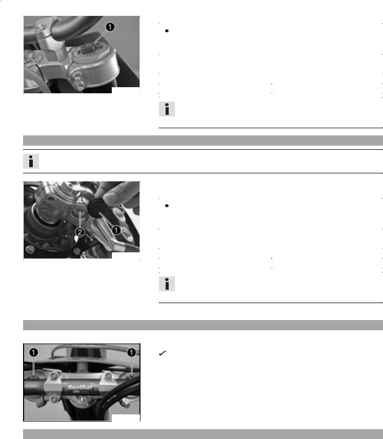
Checking basic setting of fork
Info
For various reasons, no exact riding sag can be determined for the forks.
As with the shock absorber, smaller weight differences can be compensated by the spring preload.
However, if your fork is often overloaded (hard end stop on compression), you must fit harder springs to avoid damage to the fork and frame.
400386-01
Adjusting compression damping of fork
Info
The hydraulic compression damping determines the fork suspension behavior.
MAINTENANCE WORK ON CHASSIS AND ENGINE |
26 |
|
Turn adjusting screws clockwise until they stop. |
|||||
|
|
|
|
|
|
|
|
|
|
|
|
Info |
|
|
|
|
|
|
|
|
|
|
|
|
|
The adjusting screws are located at the top end of the fork legs. |
|
|
|
|
|
|
Make the same adjustment on both fork legs. |
|
|
|
|
|
|||
|
Turn back counterclockwise the number of clicks corresponding to the fork type. |
|||||
|
|
Specification |
|
|||
|
|
|
|
|||
|
|
Compression damping |
|
|||
|
|
|
|
|
|
|
400206-10 |
|
|
|
Standard |
15 clicks |
|
|
|
|
|
|
|
|
|
|
|
|
|
|
|
Info
Turn clockwise to increase damping, turn counterclockwise to reduce suspension damping.
Adjusting rebound damping of fork
Info
The hydraulic rebound damping determines the fork suspension behavior.
|
Remove protection covers . |
|
||||
|
Turn adjusting screws clockwise until they stop. |
|||||
|
|
|
|
|
|
|
|
|
|
|
|
Info |
|
|
|
|
|
|
|
|
|
|
|
|
|
The adjusting screws are located at the bottom end of the fork legs. |
|
|
|
|
|
|
Make the same adjustment on both fork legs. |
|
|
|
|
|
|||
|
Turn back counterclockwise the number of clicks corresponding to the fork type. |
|||||
|
|
Specification |
|
|||
|
|
|
|
|||
500189-10 |
|
Rebound damping |
|
|||
|
|
|
|
|
|
|
|
|
|
|
Standard |
15 clicks |
|
|
|
|
|
|
|
|
|
|
|
|
|
|
|
Info
Turn clockwise to increase damping, turn counterclockwise to reduce suspension damping.
Mount protection covers .
Bleeding fork legs
Jack up the motorcycle. ( P. 21)
Remove bleeder screws briefly.
Any excess pressure escapes from the interior of the fork.
Mount and tighten bleeder screws.
Remove the motorcycle from the work stand. ( P. 21)
400248-10
Cleaning dust boots of fork legs
Jack up the motorcycle. ( P. 21)
Remove the fork protector. ( P. 27)
 Loading...