


 Loading...
OWNER'S MANUAL 2008
690 ENDURO EU
690 ENDURO AUS/UK
ART. NO. 3211239en
DEAR KTM CUSTOMER |
1 |
Congratulations on your decision to purchase a KTM motorcycle. You are now the owner of a state-of-the-art sports motorcycle that will give you enormous pleasure if you service and maintain it accordingly.
We wish you great pleasure riding the vehicle!
Enter the serial numbers of your vehicle below.
Chassis number ( P. 16) |
Dealer's stamp |
Engine number ( P. 17)
Key number ( P. 17)
The owner's manual corresponded to the latest state of this series at the time of printing. However, it is never possible to exclude small deviations arising from further development in design and construction.
All specifications are not binding. KTM Sportmotorcycle AG in particular reserves the right to modify or delete technical specifications, prices, colors, forms, materials, services, designs, equipment, etc., without prior notice and without specifying reasons, to adapt these to local conditions, as well as to stop production of a particular model without prior notice. KTM accepts no liability for delivery options, deviations from illustrations and descriptions, as well as printing and other errors. The models portrayed partly contain special equipment that does not belong to the regular scope of delivery.

DEAR KTM CUSTOMER |
2 |
© 2008 by KTM-Sportmotorcycle AG, Mattighofen Austria All rights reserved
Reproduction, even in part, is permitted only with the express written permission of the copyright owner.
ISO 9001(12 100 6061)
Within the meaning of the international quality management standard ISO 9001, KTM uses quality assurance processes that lead to the maximum possible quality of the products.
Issued by: TÜV Management Service
KTM-Sportmotorcycle AG
5230 Mattighofen, Austria
CONTENTS |
3 |
MEANS OF REPRESENTATION ............................................... |
7 |
IMPORTANT NOTES............................................................... |
8 |
VIEW OF VEHICLE................................................................ |
12 |
View of vehicle, front left side............................................ |
12 |
View of vehicle, rear right side ........................................... |
14 |
LOCATION OF SERIAL NUMBERS ......................................... |
16 |
Chassis number................................................................ |
16 |
Type label........................................................................ |
16 |
Key number ..................................................................... |
17 |
Engine number................................................................. |
17 |
Fork part number.............................................................. |
18 |
Shock absorber part number.............................................. |
18 |
OPERATING ELEMENTS....................................................... |
19 |
Clutch lever ..................................................................... |
19 |
Hand brake lever .............................................................. |
19 |
Light switch ..................................................................... |
20 |
Light switch ..................................................................... |
20 |
Headlight flasher switch.................................................... |
21 |
Flasher switch.................................................................. |
21 |
Flasher switch.................................................................. |
22 |
Horn ............................................................................... |
22 |
Horn ............................................................................... |
23 |
Emergency OFF switch...................................................... |
23 |
Electric starter button ....................................................... |
24 |
Ignition/steering lock ........................................................ |
24 |
Combination instrument.................................................... |
25 |
Combination instrument - function buttons ......................... |
25 |
Combination instrument - tachometer................................. |
26 |
Combination instrument - control lamps ............................. |
26 |
Combination instrument - Display ...................................... |
27 |
Combination instrument - speed display ............................. |
28 |
Setting kilometers or miles ................................................ |
28 |
Combination instrument - time .......................................... |
29 |
Setting the clock .............................................................. |
29 |
Combination instrument - ODO display ............................... |
30 |
Combination instrument - setting/resetting TRIP 1 display.... |
30 |
Combination instrument - setting/resetting TRIP 2 display.... |
31 |
Combination instrument - TRIP F display ............................ |
32 |
Combination instrument - coolant temperature indicator ...... |
32 |
Opening filler cap............................................................. |
33 |
Closing filler cap .............................................................. |
33 |
Handrails......................................................................... |
34 |
Seat release ..................................................................... |
34 |
Passenger footrests........................................................... |
35 |
Shift lever........................................................................ |
35 |
Foot brake pedal .............................................................. |
36 |
Side stand ....................................................................... |
37 |
GENERAL TIPS AND HINTS ON PUTTING INTO |
|
OPERATION......................................................................... |
38 |
Advice on first use............................................................ |
38 |
Running in the engine....................................................... |
40 |
Loading the vehicle .......................................................... |
40 |
RIDING INSTRUCTIONS ....................................................... |
42 |
Checks before putting into operation .................................. |
42 |
Starting ........................................................................... |
43 |
Starting up ...................................................................... |
45 |
Shifting, riding................................................................. |
45 |
Braking ........................................................................... |
48 |
CONTENTS |
4 |
Stopping, parking ............................................................. |
49 |
Refueling......................................................................... |
51 |
GREASING AND SERVICE TABLE .......................................... |
53 |
Important maintenance work to be carried out by an |
|
authorized KTM workshop. ................................................ |
53 |
Important maintenance work to be carried out by an |
|
authorized KTM workshop. (as additional order)................... |
55 |
MAINTENANCE WORK ON CHASSIS AND ENGINE................. |
56 |
Jacking up the motorcycle ................................................. |
56 |
Removing the motorcycle from the work stand..................... |
56 |
Fork/shock absorber.......................................................... |
57 |
Adjusting compression damping of fork .............................. |
57 |
Adjusting rebound damping of fork..................................... |
58 |
Compression damping of shock absorber............................. |
59 |
Adjusting the low-speed compression damping of the shock |
|
absorber .......................................................................... |
59 |
Adjusting high-speed compression damping of the shock |
|
absorber .......................................................................... |
60 |
Adjusting rebound damping of the shock absorber ............... |
62 |
Bleeding fork legs............................................................. |
62 |
Cleaning dust boots of fork legs ......................................... |
63 |
Loosening the fork protection............................................. |
64 |
Positioning the fork protection ........................................... |
64 |
Checking play of steering head bearing x.......................... |
65 |
Adjusting play of steering head bearing x.......................... |
66 |
Adjusting the handlebar angle x....................................... |
67 |
Handlebar position ........................................................... |
67 |
Adjusting handlebar position x........................................ |
68 |
Checking chain dirt .......................................................... |
69 |
Cleaning the chain............................................................ |
69 |
Checking the chain tension ............................................... |
70 |
Adjusting chain tension..................................................... |
71 |
Checking rear sprocket / engine sprocket for wear ................ |
73 |
Checking chain wear......................................................... |
74 |
Adjusting chain guide x.................................................. |
75 |
Checking brake discs ........................................................ |
75 |
Checking free play of hand brake lever................................ |
76 |
Adjusting free travel of handbrake lever .............................. |
77 |
Checking front brake fluid level.......................................... |
78 |
Adding brake fluid for front brake x.................................. |
78 |
Brake linings.................................................................... |
80 |
Checking the front brake linings......................................... |
81 |
Changing the front brake linings x.................................... |
81 |
Checking free play of foot brake lever ................................. |
85 |
Adjusting basic position of foot brake pedal x................... |
85 |
Checking rear brake fluid level........................................... |
86 |
Topping up brake fluid of rear brake x.............................. |
87 |
Checking the rear brake linings .......................................... |
89 |
Changing rear brake linings x.......................................... |
89 |
Removing front wheel x.................................................. |
92 |
Fitting front wheel x....................................................... |
94 |
Removing rear wheel x.................................................... |
95 |
Fitting rear wheel x........................................................ |
96 |
Checking the rear hub rubber dampers x.......................... |
97 |
Tire condition checking..................................................... |
98 |
Checking tire air pressure................................................ |
100 |
Checking spoke tension................................................... |
101 |
CONTENTS |
5 |
Removing the seat .......................................................... |
102 |
Mounting the seat .......................................................... |
103 |
Removing the battery x................................................. |
103 |
Installing the battery x.................................................. |
104 |
Recharging the battery x............................................... |
105 |
Changing the main fuse .................................................. |
107 |
Changing fuses of individual power consumers .................. |
109 |
Adjusting the engine characteristic................................... |
111 |
Removing headlight mask with headlight .......................... |
113 |
Refitting the headlight mask with the headlight................. |
114 |
Changing the headlight bulb............................................ |
115 |
Changing the parking light bulb ....................................... |
116 |
Changing the flasher bulb ............................................... |
117 |
Checking headlamp setting.............................................. |
118 |
Adjusting the headlight range .......................................... |
119 |
Removing the air filter x............................................... |
119 |
Installing the air filter x................................................ |
120 |
Cooling system ............................................................... |
121 |
Checking the antifreeze and coolant level ......................... |
122 |
Checking the coolant level............................................... |
124 |
Draining coolant x........................................................ |
126 |
Filling the cooling system x........................................... |
127 |
Adjusting basic position of clutch lever............................. |
129 |
Checking/correcting fluid level of hydraulic clutch ............. |
129 |
Checking play in gas Bowden cable .................................. |
130 |
Adjusting play in gas Bowden cable x............................. |
131 |
Removing the engine guard ............................................. |
132 |
Installing the engine guard .............................................. |
132 |
Checking engine oil level................................................. |
133 |
Changing engine oil and oil filter, cleaning oil |
|
screens x..................................................................... |
133 |
Draining engine oil x.................................................... |
134 |
Removing the oil filter x................................................ |
135 |
Mounting oil filter x...................................................... |
137 |
Cleaning oil screens x................................................... |
137 |
Filling up with engine oil x............................................ |
139 |
Topping up engine oil ..................................................... |
140 |
TROUBLESHOOTING.......................................................... |
141 |
FLASHING CODE ............................................................... |
144 |
CLEANING......................................................................... |
147 |
Cleaning motorcycle ....................................................... |
147 |
CONSERVATION FOR WINTER OPERATION ......................... |
149 |
Conservation for winter operation ..................................... |
149 |
STORAGE .......................................................................... |
150 |
Storage.......................................................................... |
150 |
Putting into operation after storage .................................. |
151 |
TECHNICAL DATA - ENGINE............................................... |
152 |
Capacity - engine oil ....................................................... |
153 |
Capacity - coolant........................................................... |
153 |
TECHNICAL DATA - ENGINE TIGHTENING TORQUES........... |
154 |
TECHNICAL DATA - CHASSIS ............................................. |
157 |
Lighting equipment ........................................................ |
158 |
Capacity - fuel................................................................ |
159 |
TECHNICAL DATA - FORK................................................... |
160 |
TECHNICAL DATA - SHOCK ABSORBER .............................. |
161 |
TECHNICAL DATA - CHASSIS TIGHTENING TORQUES ......... |
163 |
SUBSTANCES.................................................................... |
166 |
AUXILIARY SUBSTANCES................................................... |
169 |

CONTENTS |
6 |
STANDARDS...................................................................... |
171 |
INDEX ............................................................................... |
172 |
MEANS OF REPRESENTATION |
7 |
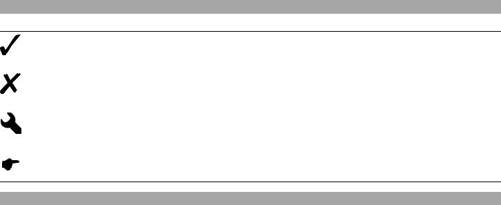
Symbols used
The symbols used are explained in the following.
Indicates an expected reaction (e.g. of a work step or a function).
Indicates an unexpected reaction (e.g. of a work step or a function).
All work marked with this symbol requires specialist knowledge and technical understanding. In the interest of your own safety, have these jobs done in an authorized KTM workshop! There, your motorcycle will be serviced optimally by specially trained experts using the specialist tools required.
Identifies a page reference (more information is provided on the specified page).
Formats used
The typographical and other formats used are explained in the following.
Eigenname |
Indicates a proprietary name. |
Name® |
Identifies a protected name. |
Marke™ |
Identifies a brand in merchandise traffic. |
|
|
IMPORTANT NOTES |
8 |
Use definition
KTM sport motorcycles are designed and constructed to meet the normal demands of regular road and light offroad operation (dirt roads), but not for use on race courses.
Info
The motorcycle is authorized for public road traffic in the homologous version only.
Maintenance
A prerequisite for perfect operation and prevention of wear is that the engine and chassis maintenance and adjustment work described in the owner's manual are properly carried out. Poor adjustment and tuning of the engine and chassis can lead to damage and breakage of components.
Using the motorcycle in extreme conditions such as very muddy or wet roads can lead to above-average wear of components such as the transmission train or the brakes. For this reason, it may be necessary to service or replace worn parts before the limit specified in the greasing and service table is reached.
Pay careful attention to the prescribed running-in period, inspection and maintenance intervals. If you observe these exactly, you will ensure a much longer service life for your motorcycle.
Warranty
The maintenance work prescribed in the greasing and service table must be carried out in an authorized KTM workshop and confirmed in the customer's service record, since otherwise no warranty claims will be recognized. No warranty claims can be considered for damage resulting from manipulations and/or alterations to the vehicle.
Fuel, oils, etc.
You should use the fuels, oils and greases according to specifications as listed in the owner's manual.
IMPORTANT NOTES |
9 |
Spare parts, accessories
For your own safety, use only spare parts and accessories approved by KTM, and have these mounted only in an authorized KTM workshop. KTM accepts no liability for other products and any resulting damage or loss.
The current KTM PowerParts for your vehicle can be found on the KTM website.
International KTM Website: http://www.ktm.com
Transport
Note
Danger of damage Danger of damage by the vehicle running away or falling over.
–Always place the vehicle on a firm and even surface.
Note
Fire hazard Some components (engine, radiator and exhaust system) get very hot when the engine is running.
–Do not place the vehicle where there are flammable or explosive substances.
–Switch off the engine and remove the ignition key.
–Use straps or other suitable devices to secure the motorcycle against accidents or falling over.
Environment
Offroad motorcycling is a wonderful sport and we naturally hope that you will be able to enjoy it to the fullest. However, it is a potential problem for the environment and can lead to conflicts with other persons. But if you use your motorcycle responsibly, you can ensure that such problems and conflicts do not have to occur. To protect the future of motorcycle sport, make sure that you use your motorcycle legally, display environmental consciousness, and respect the rights of others.

IMPORTANT NOTES |
10 |
Notes/warning notes
Pay attention to the specified notes and warnings.
Info
Various notes and warning labels are attached to the vehicle. Do not remove any notes or warning labels. If they are missing, you or others may not recognize dangers and may therefore be injured.
Grades of risks
Danger
Danger that leads immediately and certainly to severe and permanent injury or death.
Warning
Danger that will probably lead to severe and permanent injury or death.
Caution
Danger that could possibly lead to slight injuries.
Note
Danger of serious damage to machine or material.
Warning
Risk of environmental damage.
OWNER'S MANUAL
–Read this owner's manual carefully and completely before making your first trip. It contains a lot of information and tips to help you operate and handle your motorcycle. Only then will you find out how to customize the motorcycle ideally for your own use and how you can protect yourself from injury. The owner's manual also contains important information on servicing the motorcycle.
IMPORTANT NOTES |
11 |
–The owner's manual is an important component of the motorcycle and should be handed over to the new owner if the vehicle is sold.
|
VIEW OF VEHICLE |
12 |
|
|
|
|
|
|
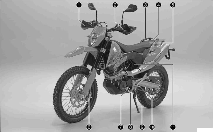
3View.1 of vehicle, front left side |
|
|
100234-10

VIEW OF VEHICLE |
13 |
1Hand brake lever
2Clutch lever
3Handrail
4Filler cap
5Seat
6Front brake caliper
7Shift lever
8Engine number
9Side stand
10Footrest
11Seat release strap
|
VIEW OF VEHICLE |
14 |
|
|
|
|
|
|
View3.2 of vehicle, rear right side |
|
|
|
|
|
|
100235-10

VIEW OF VEHICLE |
15 |
1Ignition/steering lock
2Rear mirror
3Light switch, flasher switch, horn
4Combination instrument
5Emergency OFF switch, electric starter button
6Throttle grip
7Chassis number
8Rear brake caliper
9Passenger footrest
10Shock absorber rebound damping
11Foot brake pedal
12Engine oil level viewer
LOCATION OF SERIAL NUMBERS |
16 |
4Chassis.1 number
The chassis number is stamped on the steering head on the right.
100217-10
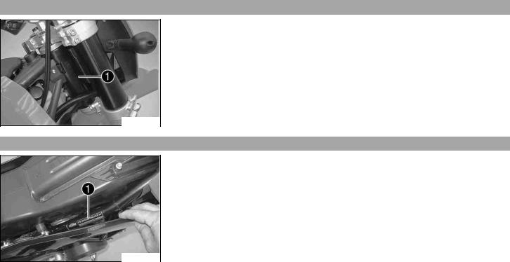
Type4.2 label
Type label is located on the upper right frame tube below the seat.
100218-10
|
LOCATION OF SERIAL NUMBERS |
17 |
||||||
|
|
|
|
|
|
|||
|
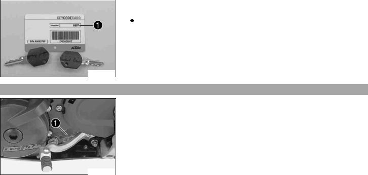
Key4.3 number |
|
|
|||||
|
|
|
The key number can be found on the KEYCODECARD. |
|
|
|||
|
|
|
|
|||||
|
|
|
|
|
|
|
|
|
|
|
|
|
|
|
Info |
|
|
|
|
|
|
|
|
|
|
|
|
|
|
|
|
|
You need the key number to order a spare key. Keep the KEYCODECARD in a safe |
|
|
|
|
|
|
|
|
place. |
|
|
|
|
|
|
|
|
|
|
|
100179-10
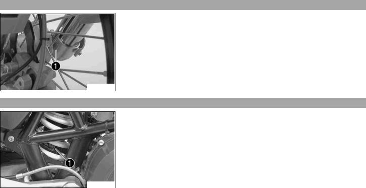
Engine4.4 number
The engine number is stamped on the left side of the engine under the engine sprocket.
100211-10
LOCATION OF SERIAL NUMBERS |
18 |
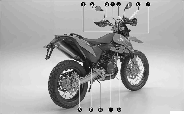
Fork4.5 part number
The fork part number is stamped on the inner side of the fork stub.
100214-10
Shock4.6 absorber part number
Shock absorber part number can be viewed from the right side.
100216-10
OPERATING ELEMENTS |
19 |
5Clutch.1 lever
The clutch lever is fitted on the left side of the handlebar.
The clutch is hydraulically operated and self-adjusting.
100219-10
Hand5.2 brake lever
The hand break lever is fitted on the right side of the handlebar.
The hand brake lever operates the front brake.
100220-10
OPERATING ELEMENTS |
20 |
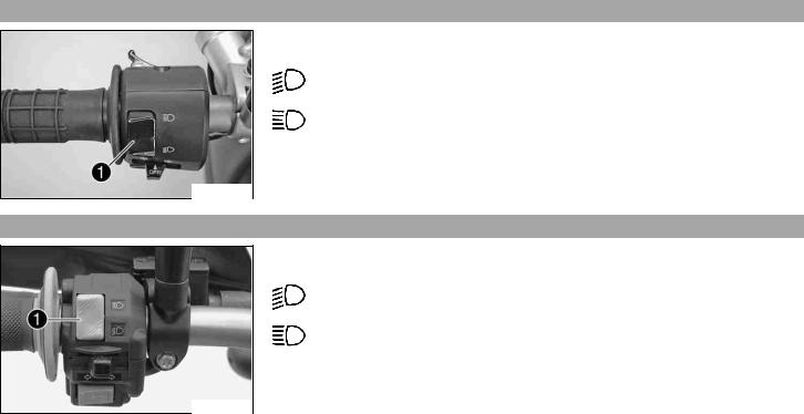
Light5.3 switch
The light switch is fitted on the left side of the handlebar.
Possible states
Low beam on – Light switch is turned downwards. In this position, the low
beam and tail light are switched on.
High beam on – Light switch is turned upwards. In this position, the high beam and the tail light are switched on.
500020-01
Light5.4 switch
The light switch is fitted on the left side of the handlebar.
Possible states
Low beam on – Light switch is turned downwards. In this position, the low
beam and tail light are switched on.
High beam on – Light switch is turned upwards. In this position, the high beam and the tail light are switched on.
100222-10
OPERATING ELEMENTS |
21 |
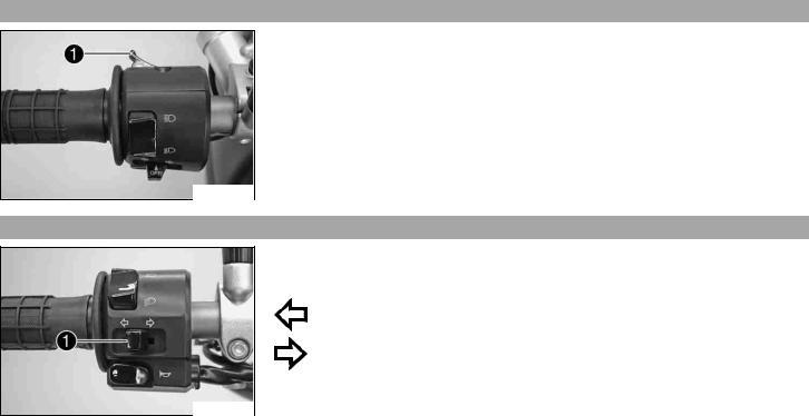
Headlight5.5 flasher switch
The headlight flasher switch is fitted on the left side of the handlebar.
Possible states
•Headlight flasher switch in neutral position
•Headlight flasher switch pressed – In this position, the headlight flasher (high beam) is actuated.
500020-11
Flasher5.6 switch
The flasher switch is fitted on the left side of the handlebar.
Possible states
Flasher light off
Flasher light, left, on – Flasher switch pressed to the right. The flasher switch returns automatically to the central position after use.
Flasher light, right, on – Flasher switch pressed to the right. The flasher switch returns automatically to the central position after use.
To switch off the flasher light, press the flasher switch towards the switch case.
500021-10
OPERATING ELEMENTS |
22 |
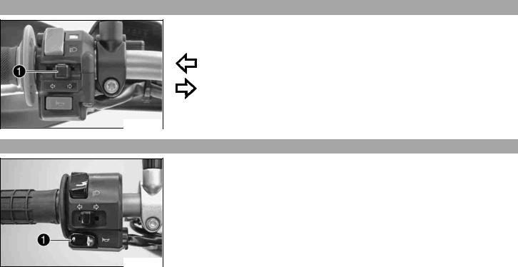
Flasher5.7 switch
The flasher switch is fitted on the left side of the handlebar.
Possible states
Flasher light off
Flasher light, left, on – Flasher switch pressed to the right. The flasher switch returns automatically to the central position after use.
Flasher light, right, on – Flasher switch pressed to the right. The flasher switch returns automatically to the central position after use.
To switch off the flasher light, press the flasher switch towards the switch case.
100223-10
Horn5.8
The horn button is fitted on the left side of the handlebar.
Possible states
•Horn button  in neutral position
•Horn button  pressed – The horn is operated in this position.
500021-11
OPERATING ELEMENTS |
23 |
Horn5.9
The horn button is fitted on the left side of the handlebar.
Possible states
•Horn button  in neutral position
•Horn button  pressed – The horn is operated in this position.
100224-10
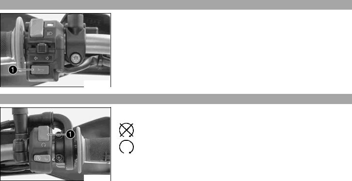
Emergency5.10 OFF switch
The emergency OFF switch is fitted on the left side of the handlebar.
Possible states
Emergency OFF switch off – In this position, the ignition circuit is interrupted, a running engine stops, and the engine cannot be started.
Emergency OFF switch on – This position is necessary for operation as the ignition circuit is closed.
100225-10
OPERATING ELEMENTS |
24 |
Electric5.11 starter button
The electric starter button is fitted on the right side of the handlebar.
Possible states
•Electric starter button  in basic position
•Electric starter button  pressed – In this position, the electric starter is actuated.
100226-10
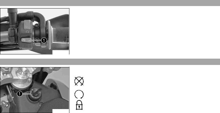
Ignition/steering5.12 lock
The ignition/steering lock is located in front of the seat.
Possible states
Ignition off – In this position, the ignition circuit is interrupted, a running engine stops, and a non-running engine will not start. The ignition key can be removed.
Ignition on – In this position, the ignition circuit is closed, and the engine can be started.
Steering locked – In this position, the ignition circuit is interrupted and the steering locked. The ignition key can be removed.
100221-10
OPERATING ELEMENTS |
25 |
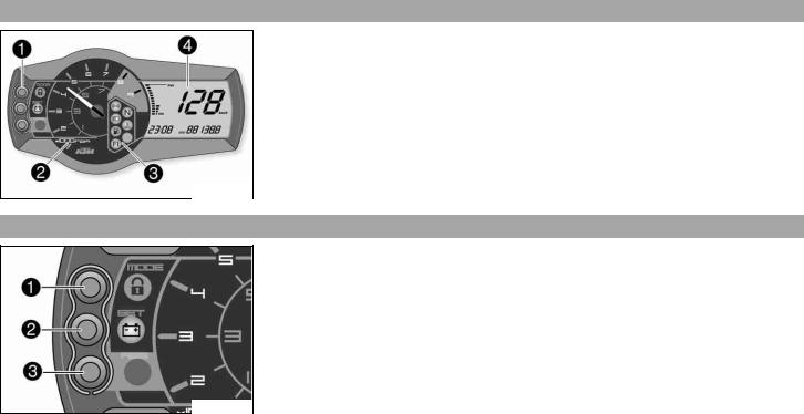
Combination5.13 instrument
The combination instrument is attached in fromt of the handlebar. The combination instrument is divided into 4 function areas.
Function buttonsTachometer
Indicator lightsDisplay
700116-01
Combination5.14 instrument - function buttons
Press the MODE button to change the display mode.
Possible display modes are total distance covered (ODO), tripmaster 1 (TRIP 1) and tripmaster 2 (TRIP 2).
Press the SET button to reset tripmaster 1 (TRIP 1) and tripmaster 2 (TRIP 2) to 0.0. Button has no function.
700117-01
OPERATING ELEMENTS |
26 |
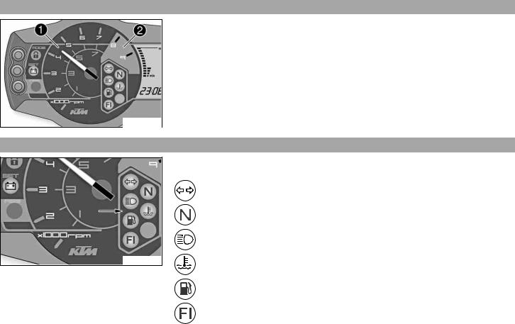
Combination5.15 instrument - tachometer
The tachometer displays the engine speed in revolutions per minute.
The red marking shows the excess engine speed range.
100118-10
Combination5.16 instrument - control lamps
100119-10
The indicator lamps provide additional information on the operating state of the motorcycle.
Possible states
Flashing indicator flashes green in flash rhythm – Flasher light is switched on.
Idling speed indicator lamp lights up green – Transmission is in neutral.
High beam indicator lamp lights up blue – High beam is switched on.
Temperature warning lamp lights up red – Coolant has reached a critical value.
Fuel level warning lamp lights up orange – Fuel level has reached the reserve mark. Display switches to TRIP F.
FI warning lamp (MIL) lights/flashes orange – The OBD has detected an emissionor safety-critical error.
OPERATING ELEMENTS |
27 |
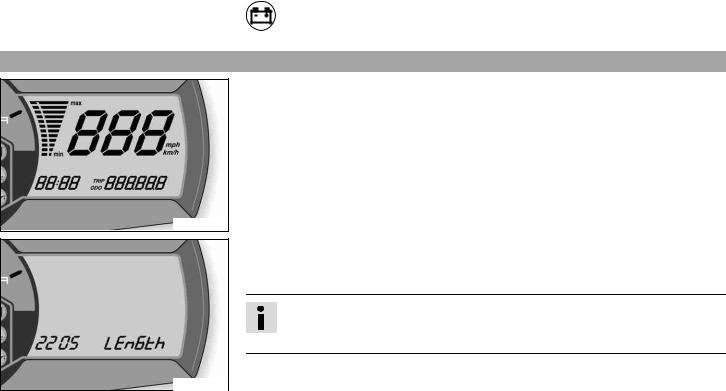
Combination5.17 instrument - Display
700118-01
400404-01
Battery warning lamp lights up – Voltage in electrical system too low.
When you switch on the ignition, all display segments light up for a second as a function test.
LEnGTth
Following the display function test, the wheel circumference LEnGth is shown for one second.
Info
2205 mm equals the circumference of the 21" front wheel with a series production tire.
The display then changes to the last selected mode.
|
OPERATING ELEMENTS |
28 |
|||
|
|
|
|
|
|
|
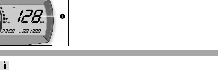
Combination5.18 |
instrument - speed display |
|
|
|
|
|
|
|
The speed is displayed in kilometers per hour km/h or miles per hour Mph. |
|
|
|
|
|
||
700114-01
Setting5.19 kilometers or miles
Info
If you change the unit, the ODO value is retained and converted accordingly.
Making the setting according to the country.
Condition
The motorcycle is standing.
Loading...