


 Loading...
OWNER'S MANUAL 2014
690 Duke EU
690 Duke AUS/UK
690 Duke R EU
690 Duke R AUS/UK
690 Duke R MAL
Art. no. 3213103en
DEAR KTM CUSTOMER |
1 |
Congratulations on your decision to purchase a KTM motorcycle. You are now the owner of a state-of-the-art sports motorcycle that will give you enormous pleasure if you service and maintain it accordingly.
We wish you a lot of enjoyment in riding this vehicle.
Enter the serial numbers of your vehicle below.
Chassis number ( p. 20) |
Dealer's stamp |
Engine number ( p. 22)
Key number ( p. 21)
The owner's manual contained the latest information for this model series at the time of going to print. Minor differences due to developments in design cannot be ruled out completely.
All specifications are non-binding. KTM Sportmotorcycle AG specifically reserves the right to modify or delete technical specifications, prices, colors, forms, materials, services, designs, equipment, etc., without prior notice and without specifying reasons, to adapt these to local conditions, as well as to stop production of a particular model without prior notice. KTM accepts no liability for delivery options,
deviations from illustrations and descriptions, as well as misprints and other errors. The models portrayed partly contain special equipment that does not belong to the regular scope of supply.
© 2013 KTM-Sportmotorcycle AG, Mattighofen Austria All rights reserved
Reproduction, even in part, as well as copying of all kinds, is permitted only with the express written permission of the copyright owner.

DEAR KTM CUSTOMER |
2 |
ISO 9001(12 100 6061)
According to the international quality management standard ISO 9001, KTM uses quality assurance processes that lead to the maximum possible quality of the products.
Issued by: TÜV Management Service
KTM-Sportmotorcycle AG
5230 Mattighofen, Austria
TABLE OF CONTENTS
1 |
MEANS OF REPRESENTATION ........................................ |
7 |
|
|
1.1 |
Symbols used ...................................................... |
7 |
|
1.2 |
Formats used....................................................... |
7 |
2 |
SAFETY ADVICE.............................................................. |
8 |
|
|
2.1 |
Use definition - intended use ................................ |
8 |
|
2.2 |
Safety advice....................................................... |
8 |
|
2.3 |
Degrees of risk and symbols .................................. |
9 |
|
2.4 |
Tampering warning............................................... |
9 |
|
2.5 |
Safe operation ................................................... |
10 |
|
2.6 |
Protective clothing ............................................. |
11 |
|
2.7 |
Work rules......................................................... |
11 |
|
2.8 |
Environment...................................................... |
11 |
|
2.9 |
Owner's Manual ................................................. |
12 |
3 |
IMPORTANT INFORMATION .......................................... |
13 |
|
|
3.1 |
Guarantee, warranty ........................................... |
13 |
|
3.2 |
Operating and auxiliary substances ...................... |
13 |
|
3.3 |
Spare parts, accessories ..................................... |
13 |
|
3.4 |
Service ............................................................. |
13 |
|
3.5 |
Figures ............................................................. |
14 |
|
3.6 |
Customer service................................................ |
14 |
4 |
VIEW OF VEHICLE ........................................................ |
16 |
|
|
4.1 |
View of vehicle, front left side (example) .............. |
16 |
|
4.2 |
View of vehicle, rear right side (example).............. |
18 |
5 |
SERIAL NUMBERS ....................................................... |
20 |
|
|
5.1 |
Chassis number ................................................. |
20 |
|
5.2 |
Type label ......................................................... |
20 |
|
5.3 |
Key number....................................................... |
21 |
|
5.4 |
Engine number .................................................. |
22 |
|
5.5 |
Fork part number ............................................... |
23 |
|
|
|
3 |
5.6 |
Shock absorber part number ............................... |
23 |
|
6 CONTROLS................................................................... |
25 |
||
6.1 |
Clutch lever....................................................... |
25 |
|
6.2 |
Hand brake lever................................................ |
25 |
|
6.3 |
Throttle grip ...................................................... |
26 |
|
6.4 |
Horn button....................................................... |
27 |
|
6.5 |
Light switch ...................................................... |
27 |
|
6.6 |
Headlight flasher switch ..................................... |
28 |
|
6.7 |
Turn signal switch.............................................. |
28 |
|
6.8 |
Emergency OFF switch ....................................... |
29 |
|
6.9 |
Electric starter button......................................... |
29 |
|
6.10 |
Ignition/steering lock.......................................... |
30 |
|
6.11 |
Combination instrument ..................................... |
30 |
|
6.11.1 |
|
Overview ....................................................... |
30 |
6.11.2 |
|
function buttons ............................................ |
31 |
6.11.3 |
|
Tachometer ................................................... |
31 |
6.11.4 |
|
Combination instrument - indicator lamps ........ |
32 |
6.11.5 |
|
Display ......................................................... |
33 |
6.11.6 |
|
Speed display................................................ |
34 |
6.11.7 |
Setting kilometers or miles ............................. |
34 |
|
6.11.8 |
|
Time............................................................. |
35 |
6.11.9 |
|
Setting the clock ........................................... |
35 |
6.11.10 |
ODO display .................................................. |
36 |
|
6.11.11 |
Setting/resetting display TRIP 1 ...................... |
36 |
|
6.11.12 |
Setting/resetting display TRIP 2 ...................... |
37 |
|
6.11.13 |
TRIP F display............................................... |
38 |
|
6.11.14 |
GEAr display ................................................. |
38 |
|
6.11.15 |
Coolant temperature indicator ......................... |
39 |
|
6.12 |
Opening the filler cap......................................... |
39 |
|
TABLE OF CONTENTS
|
6.13 |
Closing the filler cap .......................................... |
40 |
|
6.14 |
Seat lock........................................................... |
41 |
|
6.15 |
Tool set............................................................. |
41 |
|
6.16 |
Handrails .......................................................... |
42 |
|
6.17 |
Passenger footrests ............................................ |
42 |
|
6.18 |
Shift lever ......................................................... |
43 |
|
6.19 |
Foot brake lever ................................................. |
45 |
|
6.20 |
Side stand......................................................... |
46 |
7 |
PREPARING FOR USE................................................... |
47 |
|
|
7.1 |
Advice on first use ............................................. |
47 |
|
7.2 |
Running in the engine ........................................ |
48 |
|
7.3 |
Loading the vehicle ............................................ |
49 |
8 |
RIDING INSTRUCTIONS................................................ |
51 |
|
8.1Performing checks and vehicle care when
|
|
preparing for use................................................ |
51 |
|
8.2 |
Starting............................................................. |
52 |
|
8.3 |
Starting off........................................................ |
54 |
|
8.4 |
Shifting, riding .................................................. |
54 |
|
8.5 |
Applying the brakes............................................ |
58 |
|
8.6 |
Stopping, parking............................................... |
60 |
|
8.7 |
Transport .......................................................... |
61 |
|
8.8 |
Refueling .......................................................... |
62 |
9 |
SERVICE SCHEDULE .................................................... |
64 |
|
|
9.1 |
Service schedule................................................ |
64 |
10 |
TUNING THE CHASSIS ................................................. |
66 |
|
|
10.1 |
Fork/shock absorber (Duke R).............................. |
66 |
10.2Adjusting the compression damping of the fork
(Duke R) ........................................................... |
66 |
10.3Adjusting the rebound damping of the fork
(Duke R) ........................................................... |
67 |
4
10.4 Compression damping of the shock absorber......... |
68 |
10.5Adjusting the high-speed compression damping
of the shock absorber (Duke R) ........................... |
68 |
10.6Adjusting the low-speed compression damping of
the shock absorber (Duke R) ............................... |
69 |
10.7Adjusting the rebound damping of the shock
|
absorber (Duke R) .............................................. |
70 |
10.8 |
Adjusting the spring preload of the shock |
|
|
absorber x....................................................... |
71 |
10.9 |
Adjusting the footrests........................................ |
73 |
10.10 |
Adjusting the foot brake lever stub (Duke R) ......... |
76 |
11 SERVICE WORK ON THE CHASSIS................................. |
77 |
|
11.1Raising the motorcycle with the rear wheel
stand ................................................................ |
77 |
11.2Taking the motorcycle off of the rear wheel
stand ................................................................ |
77 |
11.3Raising the motorcycle with the front wheel
stand ................................................................ |
78 |
11.4Taking the motorcycle off of the front wheel
|
stand ................................................................ |
79 |
11.5 |
Removing the passenger seat .............................. |
79 |
11.6 |
Mounting the passenger seat............................... |
80 |
11.7 |
Removing the passenger seat cover (Duke R) ........ |
80 |
11.8 |
Mounting the passenger seat cover (Duke R)......... |
81 |
11.9 |
Checking the chain for dirt.................................. |
81 |
11.10 |
Cleaning the chain ............................................. |
82 |
11.11 |
Checking the chain tension ................................. |
83 |
11.12 |
Adjusting the chain tension................................. |
85 |
11.13 |
Checking the chain, rear sprocket and engine |
|
|
sprocket............................................................ |
87 |
TABLE OF CONTENTS |
|
|
11.14 |
Adjusting the basic position of the clutch lever ..... |
89 |
11.15 |
Checking/rectifying the fluid level of the |
|
|
hydraulic clutch................................................. |
90 |
12 BRAKE SYSTEM ........................................................... |
91 |
|
12.1 |
ABS/antilock brake system.................................. |
91 |
12.2Adjusting the basic position of the hand brake
|
|
lever ................................................................. |
92 |
|
12.3 |
Checking the brake discs .................................... |
93 |
|
12.4 |
Checking the brake fluid level of the front brake ... |
94 |
|
12.5 |
Adding front brake fluid x................................. |
95 |
|
12.6 |
Checking the front brake linings .......................... |
97 |
|
12.7 |
Checking the free travel of foot brake lever ........... |
98 |
|
12.8 |
Adjusting the basic position of the foot brake |
|
|
|
lever x............................................................ |
99 |
|
12.9 |
Checking rear brake fluid level .......................... |
102 |
|
12.10 |
Adding rear brake fluid x................................ |
103 |
|
12.11 |
Checking the rear brake linings ......................... |
105 |
13 |
WHEELS, TIRES ......................................................... |
106 |
|
|
13.1 |
Removing the front wheel x............................ |
106 |
|
13.2 |
Installing the front wheel x............................. |
107 |
|
13.3 |
Removing the rear wheel x.............................. |
110 |
|
13.4 |
Installing the rear wheel x.............................. |
111 |
|
13.5 |
Checking the rear hub rubber dampers x.......... |
114 |
|
13.6 |
Checking the tire condition ............................... |
115 |
|
13.7 |
Checking the tire pressure ................................ |
117 |
14 |
ELECTRICAL SYSTEM ................................................. |
118 |
|
|
14.1 |
Removing the battery x.................................. |
118 |
|
14.2 |
Installing the battery x................................... |
119 |
|
14.3 |
Recharging the battery x................................ |
120 |
|
|
5 |
14.4 |
Changing the main fuse.................................... |
123 |
14.5 |
Changing the ABS fuses ................................... |
125 |
14.6Changing the fuses of individual power
consumers....................................................... |
126 |
14.7Removing the headlight mask with the
headlight......................................................... |
129 |
14.8Refitting the headlight mask with the
|
headlight......................................................... |
130 |
14.9 |
Changing the headlight bulb ............................. |
131 |
14.10 |
Changing the parking light bulb......................... |
133 |
14.11 |
Changing the turn signal bulb (Duke) ................. |
134 |
14.12 |
Checking the headlight setting .......................... |
135 |
14.13 |
Adjusting the headlight range............................ |
136 |
15 COOLING SYSTEM ...................................................... |
137 |
|
15.1 |
Cooling system ................................................ |
137 |
15.2 |
Checking the antifreeze and coolant level ........... |
137 |
15.3Checking the coolant level in the compensating
|
tank................................................................ |
140 |
15.4 |
Draining the coolant x.................................... |
141 |
15.5 |
Filling/bleeding the cooling system x............... |
142 |
16 TUNING THE ENGINE................................................. |
144 |
|
16.1 |
Setting the engine characteristics...................... |
144 |
16.2 |
Checking the basic position of the shift lever ...... |
145 |
16.3 |
Adjusting the basic position of the shift |
|
|
lever x.......................................................... |
145 |
17 SERVICE WORK ON THE ENGINE ................................ |
148 |
|
17.1 |
Checking the engine oil level............................. |
148 |
17.2 |
Changing the engine oil and filter, cleaning the |
|
|
oil screens x.................................................. |
148 |
17.3 |
Adding engine oil............................................. |
153 |
TABLE OF CONTENTS |
|
|
6 |
18 CLEANING, CARE ....................................................... |
154 |
INDEX ............................................................................... |
192 |
18.1 Cleaning the motorcycle ................................... |
154 |
|
|
18.2Checks and maintenance steps for winter
|
|
operation......................................................... |
156 |
19 |
STORAGE................................................................... |
157 |
|
|
19.1 |
Storage ........................................................... |
157 |
|
19.2 |
Preparing for use after storage........................... |
158 |
20 |
TROUBLESHOOTING .................................................. |
159 |
|
21 |
BLINK CODE .............................................................. |
162 |
|
22 |
TECHNICAL DATA....................................................... |
169 |
|
|
22.1 |
Engine ............................................................ |
169 |
|
22.2 |
Engine tightening torques ................................. |
170 |
|
22.3 |
Capacities ....................................................... |
173 |
|
22.3.1 |
Engine oil ................................................... |
173 |
|
22.3.2 |
Coolant ....................................................... |
174 |
|
22.3.3 |
Fuel ........................................................... |
174 |
|
22.4 |
Chassis ........................................................... |
174 |
|
22.5 |
Electrical system.............................................. |
176 |
|
22.6 |
Tires ............................................................... |
177 |
|
22.7 |
Fork................................................................ |
177 |
|
22.7.1 |
Duke .......................................................... |
177 |
|
22.7.2 |
Duke R ....................................................... |
177 |
|
22.8 |
Shock absorber................................................ |
178 |
|
22.8.1 |
Duke .......................................................... |
178 |
|
22.8.2 |
Duke R ....................................................... |
179 |
|
22.9 |
Chassis tightening torques ................................ |
180 |
23 |
SUBSTANCES ............................................................ |
185 |
|
24 |
AUXILIARY SUBSTANCES ........................................... |
189 |
|
25 |
STANDARDS .............................................................. |
191 |
|
1 |
MEANS OF REPRESENTATION |
7 |
1.1Symbols used
The meaning of specific symbols is described below.
Indicates an expected reaction (e.g. of a work step or a function).
Indicates an unexpected reaction (e.g. of a work step or a function).
All work marked with this symbol requires specialist knowledge and technical understanding. In the interest of your own safety, have these jobs performed by an authorized KTM workshop. There, your motorcycle will be optimally cared for by specially trained experts using the specialist tools required.
Indicates a page reference (more information is provided on the specified page).
1.2Formats used
The typographical formats used in this document are explained below.
Specific name |
Identifies a proprietary name. |
Name® |
Identifies a protected name. |
Brand™ |
Identifies a brand available on the open market. |
|
|
2 |
SAFETY ADVICE |
8 |
2.1Use definition - intended use
KTM sport motorcycles are designed and constructed to meet the normal demands of regular road operation but not for use on race courses or offroad.
Info
The motorcycle is only authorized for operation on public roads in the homologated version.
2.2Safety advice
A number of safety instructions need to be followed to operate the vehicle safely. Therefore, read this manual carefully. The safety instructions are highlighted in the text and are referred to at the relevant passages.
Info
The vehicle has various information and warning labels at prominent locations. Do not remove information/warning labels. If they are missing, you or others may not recognize dangers and may therefore be injured.
2 |
SAFETY ADVICE |
9 |
2.3Degrees of risk and symbols
Danger
Identifies a danger that will immediately and invariably lead to fatal or serious permanent injury if the appropriate measures are not taken.
Warning
Identifies a danger that is likely to lead to fatal or serious injury if the appropriate measures are not taken.
Caution
Identifies a danger that may lead to minor injuries if the appropriate measures are not taken.
Note
Identifies a danger that will lead to considerable machine and material damage if the appropriate measures are not taken.
Warning
Identifies a danger that will lead to environmental damage if the appropriate measures are not taken.
2.4Tampering warning
Tampering with the noise control system is prohibited. Federal law prohibits the following acts or the causing thereof:
1The removal or rendering inoperative by any person other than for purposes of maintenance, repair, or replacement, of any device or element of design incorporated into any new vehicle for the purpose of noise control prior to its sale or delivery to the ultimate purchaser or while it is in use, or
2the use of the vehicle after such device or element of design has been removed or rendered inoperative by any person.
Among those acts presumed to constitute tampering are the acts listed below:
2 |
SAFETY ADVICE |
10 |
1Removal or puncturing of the main silencer, baffles, header pipes or any other components which conduct exhaust gases.
2Removal or puncturing of parts of the intake system.
3Lack of proper maintenance.
4Replacing moving part of the vehicle, or parts of the exhaust or intake system, with parts other than those specified by the manufacturer.
2.5Safe operation
Danger
Danger of accidents Danger arising from the rider's judgement being impaired.
–Do not operate the vehicle while under the influence of alcohol, drugs and certain medications or physically or mentally impaired.
Danger
Danger of poisoning Exhaust gases are toxic and inhaling them may result in unconsciousness and/or death.
–When running the engine, always make sure there is sufficient ventilation, and do not start or run the engine in an enclosed space without an effective exhaust extraction system.
Warning
Danger of burns Some vehicle components become very hot when the vehicle is operated.
–Do not touch hot components such as exhaust system, radiator, engine, shock absorber, and the brake system. Allow these components to cool down before starting work on them.
Only operate the vehicle when it is in perfect technical condition, in accordance with its intended use, and in a safe and environmentally compatible manner.
An appropriate driver's license is needed to ride the vehicle on public roads.
Have malfunctions that impair safety promptly eliminated by an authorized KTM workshop. Adhere to the information and warning labels on the vehicle.
2 |
SAFETY ADVICE |
11 |
2.6Protective clothing
Warning
Risk of injury Missing or poor protective clothing presents an increased safety risk.
–Wear protective clothing (helmet, boots, gloves, pants and jacket with protectors) every time you ride the vehicle. Always wear protective clothing that is in good condition and meets the legal requirements.
In the interest of your own safety, KTM recommends that you only operate the vehicle while wearing protective clothing.
2.7Work rules
Special tools are necessary for certain tasks. The tools are not contained in the vehicle but can be ordered under the number in parentheses. E.g.: bearing puller (15112017000)
During assembly, non-reusable parts (e.g. self-locking screws and nuts, seals and seal rings, O-rings, pins, lock washers) must be replaced by new parts.
In some instances, a thread locker (e.g. Loctite®) is required. The manufacturer instructions for use must be followed.
After disassembly, clean the parts that are to be reused and check them for damage and wear. Change damaged or worn parts. After you complete the repair or service work, check the operating safety of the vehicle.
2.8Environment
If you use your motorcycle responsibly, you can ensure that problems and conflicts do not occur. To protect the future of the motorcycle sport, make sure that you use your motorcycle legally, display environmental consciousness, and respect the rights of others.
When disposing of used oil, other operating and auxiliary fluids, and used components, comply with the laws and regulations of the respective country.
Because motorcycles are not subject to the EU regulations governing the disposal of used vehicles, there are no legal regulations that pertain to the disposal of an end-of-life motorcycle. Your authorized KTM dealer will be glad to advise you.

2 |
SAFETY ADVICE |
12 |
2.9Owner's Manual
It is important that you read this Owner's Manual carefully and completely before making your first trip. The Owner's Manual contains useful information and many tips on how to operate, handle, and maintain your motorcycle. Only then will you find out how to customize the vehicle ideally for your own use and how you can protect yourself from injury.
Keep the Owner's Manual in an accessible place to enable you to refer to it as needed.
If you would like to know more about the vehicle or have questions on the material you read, please contact an authorized KTM dealer. The Owner's Manual is an important component of the vehicle and should be handed over to the new owner if the vehicle is sold.
3 |
IMPORTANT INFORMATION |
13 |
3.1Guarantee, warranty
The work prescribed in the service schedule must be carried out by an authorized KTM workshop only and confirmed in the customer's Service & Warranty Booklet and in the KTM dealer.net; otherwise, all warranty claims will be void. No warranty claims can be considered for damage resulting from manipulations and/or alterations to the vehicle.
Additional information on the guarantee or warranty and the procedures involved can be found in the Service & Warranty Booklet.
3.2Operating and auxiliary substances
Warning
Environmental hazard Improper handling of fuel is a danger to the environment.
–Do not allow fuel to get into the ground water, the ground, or the sewage system.
Use operating and auxiliary substances (such as fuel and lubricants) as specified in the Owner's Manual.
3.3Spare parts, accessories
For your own safety, only use spare parts and accessory products that are approved and/or recommended by KTM and have them installed by an authorized KTM workshop. KTM accepts no liability for other products and any resulting damage or loss.
Certain spare parts and accessory products are specified in parentheses in the descriptions. Your authorized KTM dealer will be glad to advise you.
The current KTM PowerParts for your vehicle can be found on the KTM website.
International KTM Website: http://www.ktm.com
3.4Service
A prerequisite for perfect operation and prevention of premature wear is that the service, care, and tuning work on the engine and chassis is properly carried out as described in the Owner's Manual. Incorrect adjustment and tuning of the engine and chassis can lead to damage and breakage of components.

3 |
IMPORTANT INFORMATION |
14 |
Use of the vehicle under difficult conditions, such as on sand or on wet and muddy surfaces, can lead to considerably more rapid wear of components such as the drive train, brake system, or suspension components. For this reason, it may be necessary to inspect or replace parts before the next scheduled service.
It is imperative that you adhere to the stipulated run-in times and service intervals. If you observe these exactly, you will ensure a much longer service life for your motorcycle.
3.5Figures
The figures contained in the manual may depict special equipment.
In the interest of clarity, some components may be shown disassembled or may not be shown at all. It is not always necessary to disassemble the component to perform the activity in question. Please follow the instructions in the text.
3.6Customer service
Your authorized KTM dealer will be happy to answer any questions you may have on your vehicle and KTM.
A list of authorized KTM dealers can be found on the KTM website.
International KTM Website: http://www.ktm.com
15

4 |
VIEW OF VEHICLE |
16 |
4.1View of vehicle, front left side (example)
C00298-10

4 |
VIEW OF VEHICLE |
17 |
1Clutch lever ( p. 25)
2Seat
3Passenger seat
4Handrails ( p. 42)
5Seat lock ( p. 41)
6Engine number ( p. 22)
7Shift lever ( p. 43)
8Side stand ( p. 46)

4 |
VIEW OF VEHICLE |
18 |
4.2View of vehicle, rear right side (example)
101969-10

4 |
VIEW OF VEHICLE |
19 |
|
|
|
1 |
Tool set ( p. 41) |
|
1Map Select switch
2Light switch ( p. 27)
2 |
Headlight flasher switch ( p. 28) |
|
|
2 |
Turn signal switch ( p. 28) |
2Horn button ( p. 27)
3Filler cap
4Ignition/steering lock ( p. 30)
5Emergency OFF switch ( p. 29)
5Electric starter button ( p. 29)
6Hand brake lever ( p. 25)
7Chassis number ( p. 20)
8Fuse box
9Type label ( p. 20)
10Passenger footrests ( p. 42)
11Foot brake lever ( p. 45)
12Level viewer, engine oil

5 |
SERIAL NUMBERS |
20 |
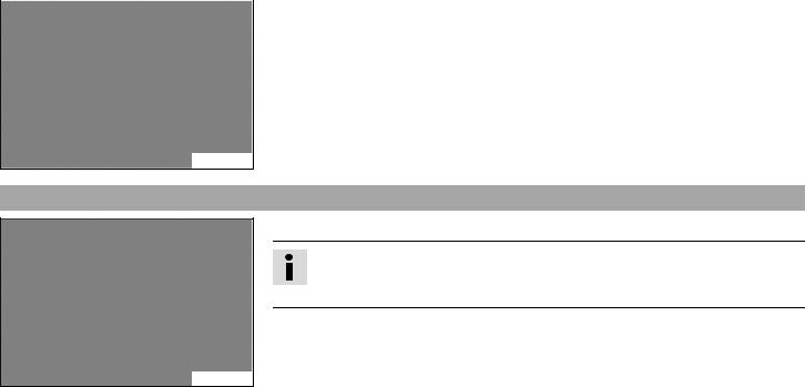
5.1Chassis number
The chassis number 1 is stamped on the right side of the steering head.
602542-10
5.2Type label
The type label 1 is located on the right side of the frame.
C00301-10
5 |
SERIAL NUMBERS |
21 |
|
|
|
|
(690 Duke AUS/UK, 690 Duke R AUS/UK) |
|
|
|
|
|
|
|
The type label 1 is located on the left side of the frame. |
101970-10
5.3Key number
The key number 1 can be found on the KEYCODECARD.
Info
You need the key number to order a spare key. Keep the KEYCODECARD in a safe place.
B00755-10

5 |
SERIAL NUMBERS |
22 |
5.4Engine number
(Duke)
The engine number 1 is located on the left side of the engine under the engine sprocket.
C00302-10
(Duke R)
The engine number 1 is located on the left side of the engine under the engine sprocket.
602550-10

5 |
SERIAL NUMBERS |
23 |
5.5Fork part number
The fork part number 1 is stamped on the inner side of the fork stub.
C00303-10
5.6Shock absorber part number
(Duke)
The shock absorber part number 1 is on the left side of the shock absorber.
C00304-10

5 |
SERIAL NUMBERS |
24 |
|
|
|
|
(Duke R) |
|
|
|
|
|
|
|
The shock absorber part number 1 is found on the damper at the rear. |
602551-10

6 |
CONTROLS |
25 |
6.1Clutch lever
The clutch lever 1 is fitted on the left side of the handlebar.
The clutch is hydraulically operated and self-adjusting.
101963-10
6.2Hand brake lever
(Duke)
The hand brake lever 1 is fitted on the right side of the handlebar.
602570-10

6 CONTROLS
26
(Duke R)
The hand brake lever 1 is fitted on the right side of the handlebar. The front brake is engaged using the hand brake lever.
602552-10
6.3Throttle grip
The throttle grip 1 is fitted on the right side of the handlebar.
B00922-10
6 |
CONTROLS |
27 |
6.4Horn button
The horn button 1 is fitted on the left side of the handlebar.
Possible states
•Horn button  in neutral position
•Horn button  pressed – The horn is operated in this position.
C00308-11
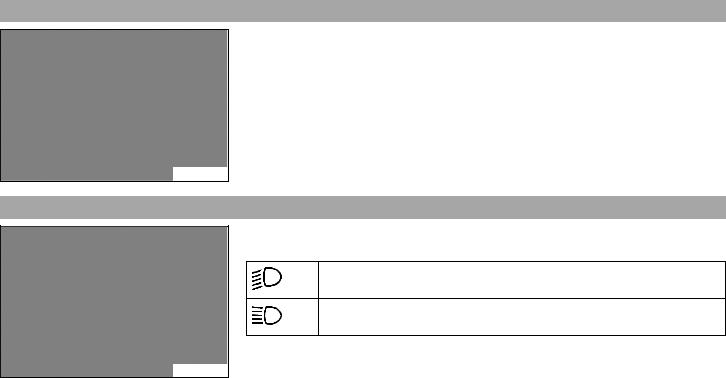
6.5Light switch
The light switch 1 is fitted on the left side of the handlebar.
Possible states
Low beam on – Light switch is turned downwards. In this position, the low beam and tail light are switched on.
High beam on – Light switch is turned upwards. In this position, the high beam and the tail light are switched on.
C00307-10
6 |
CONTROLS |
28 |
6.6Headlight flasher switch
The headlight flasher switch 1 is fitted on the left side of the handlebar.
Possible states
•Headlight flasher switch in neutral position
•Headlight flasher switch pressed – In this position, the headlight flasher (high beam) is actuated.
C00307-11
6.7Turn signal switch
C00308-10
The turn signal switch 1 is fitted on the left side of the handlebar.
Possible states
Turn signal off
Left turn signal on – The turn signal switch is pressed to the left. The turn signal switch automatically returns to the central position after use.
Right turn signal on – The turn signal switch is pressed to the right. The turn signal switch automatically returns to the central position after use.
To switch off the turn signal, press the turn signal switch towards the switch housing.
Loading...