


690 SMC R 2012
Table of contents
 Loading...
OWNER'S MANUAL 2012
690 SMC R EU
690 SMC R AUS/UK
Art. no. 3211790en

DEAR KTM CUSTOMER 1
DEARKTM CUSTOMER
Congratulations on your decision to purchase a KTM motorcycle. You are now the owner of a state-of-the-art sports motorcycle that will
give you enormous pleasure if you service and maintain it accordingly.
We wish you a lot of enjoyment in riding this vehicle.
Enter the serial numbers of your vehicle below.
Chassis number ( p. 16) Dealer's stamp
Engine number ( p. 17)
Key number ( p. 17)
The Owner's Manual contained the latest information for this model at the time of going to print. Minor differences due to developments in
design cannot be ruled out completely.
All specifications are non-binding. KTM Sportmotorcycle AG specifically reserves the right to modify or delete technical specifications,
prices, colors, forms, materials, services, designs, equipment, etc., without prior notice and without specifying reasons, to adapt these
to local conditions, as well as to stop production of a particular model without prior notice. KTM accepts no liability for delivery options,
deviations from illustrations and descriptions, as well as misprints and other errors. The models portrayed partly contain special equipment
that does not belong to the regular scope of delivery.

DEAR KTM CUSTOMER 2
© 2012 KTM-Sportmotorcycle AG, Mattighofen Austria
All rights reserved
Reproduction, even in part, as well as copying of all kinds, is permitted only with the express written permission of the copyright owner.
ISO 9001(12 100 6061)
According to the international quality management standard ISO 9001, KTM uses quality assurance processes that lead to
the maximum possible quality of the products.
Issued by: TÜV Management Service
KTM-Sportmotorcycle AG
5230 Mattighofen, Austria

TABLE OF CONTENTS 3
TABLEOF CONTENTS
MEANS OF REPRESENTATION ............................................... 6
IMPORTANT INFORMATION ................................................... 7
VIEW OF VEHICLE................................................................ 12
View of vehicle, front left side (example)............................. 12
View of vehicle, rear right side (example) ............................ 14
SERIAL NUMBERS............................................................... 16
Chassis number................................................................ 16
Type label........................................................................ 16
Engine number................................................................. 17
Key number ..................................................................... 17
Fork part number.............................................................. 18
Shock absorber part number .............................................. 18
CONTROLS.......................................................................... 19
Clutch lever ..................................................................... 19
Hand brake lever .............................................................. 19
Throttle grip..................................................................... 20
Light switch..................................................................... 20
Turn signal switch ............................................................ 21
Horn button ..................................................................... 21
Emergency OFF switch ...................................................... 22
Electric starter button ....................................................... 22
Ignition/steering lock ........................................................ 23
Combination instrument .................................................... 23
Combination instrument - function buttons ......................... 24
Combination instrument - tachometer................................. 24
Combination instrument - indicator lamps........................... 25
Combination instrument - display....................................... 26
Combination instrument - speedometer............................... 27
Setting kilometers or miles ................................................ 27
Combination instrument - time .......................................... 28
Setting the clock .............................................................. 28
Combination instrument - display ODO ............................... 29
Combination instrument - setting/resetting TRIP 1............... 29
Combination instrument - setting/resetting TRIP 2............... 30
Combination instrument - TRIP F display............................ 31
Combination instrument - coolant temperature indicator ...... 31
Opening the filler cap ....................................................... 32
Closing filler cap .............................................................. 33
Seat release..................................................................... 33
Handrails......................................................................... 34
Passenger footrests........................................................... 34
Shift lever........................................................................ 35
Foot brake lever................................................................ 36
Side stand ....................................................................... 36
PREPARING FOR USE .......................................................... 37
Advice on first use............................................................ 37
Running in the engine....................................................... 38
Loading the vehicle .......................................................... 39
RIDING INSTRUCTIONS ....................................................... 41
Performing checks and vehicle care when preparing for
use ................................................................................. 41
Starting ........................................................................... 42
Starting off ...................................................................... 43
Shifting, riding................................................................. 43
Braking ........................................................................... 47
Stopping, parking ............................................................. 48
Refueling......................................................................... 49
Handlebar position ........................................................... 51

TABLE OF CONTENTS 4
Adjusting the handlebar position x................................... 52
SERVICE SCHEDULE............................................................ 53
Service schedule .............................................................. 53
TUNING THE CHASSIS......................................................... 56
Fork/shock absorber.......................................................... 56
Adjusting the compression damping of the fork ................... 56
Adjusting the rebound damping of the fork.......................... 57
Compression damping of the shock absorber ....................... 58
Adjusting the low-speed compression damping of the shock
absorber .......................................................................... 58
Adjusting the high-speed compression damping of the
shock absorber................................................................. 59
Adjusting the rebound damping of the shock absorber.......... 60
SERVICE WORK ON THE CHASSIS ........................................ 62
Raising the motorcycle with the front wheel stand ............... 62
Taking the motorcycle off of the front wheel stand ............... 62
Raising the motorcycle with the rear wheel stand................. 63
Taking the motorcycle off of the rear wheel stand ................ 63
Bleeding the fork legs ....................................................... 64
Removing the seat............................................................ 64
Mounting the seat ............................................................ 65
Removing the air filter x ................................................. 65
Installing the air filter x .................................................. 66
Checking the chain for dirt ................................................ 67
Cleaning the chain............................................................ 68
Checking the chain tension ............................................... 69
Adjusting the chain tension ............................................... 70
Check the chain, rear sprocket, engine sprocket, and chain
guide............................................................................... 71
Adjusting basic position of clutch lever............................... 75
Checking/rectifying the fluid level of the hydraulic clutch ..... 76
BRAKES.............................................................................. 77
Adjusting the basic position of the hand brake lever............. 77
Checking the brake discs................................................... 77
Checking the front brake fluid level .................................... 78
Adding front brake fluid x ............................................... 79
Checking the front brake linings......................................... 80
Checking the free travel of foot brake lever.......................... 81
Adjusting the basic position of the foot brake lever x ......... 82
Checking rear brake fluid level ........................................... 83
Adding rear brake fluid x ................................................ 83
Checking the rear brake linings .......................................... 85
WHEELS, TIRES .................................................................. 87
Removing front wheel x .................................................. 87
Installing the front wheel x.............................................. 88
Removing rear wheel x.................................................... 90
Installing the rear wheel x............................................... 91
Checking the rear hub rubber dampers x .......................... 93
Checking the tire condition................................................ 95
Tubeless tire system ......................................................... 97
Checking the tire air pressure ............................................ 97
Checking the spoke tension ............................................... 98
ELECTRICAL SYSTEM ........................................................ 100
Removing the battery x................................................. 100
Installing the battery x.................................................. 101
Recharging the battery x............................................... 102
Changing the main fuse .................................................. 105

TABLE OF CONTENTS 5
Changing fuses of individual power consumers .................. 106
Removing the headlight mask with the headlight ............... 108
Installing the headlight mask with the headlight ................ 110
Changing the headlight bulb ............................................ 111
Changing the parking light bulb ....................................... 113
Changing the turn signal bulb .......................................... 114
Checking the headlight setting......................................... 115
Adjusting the headlight range .......................................... 116
COOLING SYSTEM ............................................................. 117
Cooling system............................................................... 117
Checking the antifreeze and coolant level ......................... 117
Checking the coolant level............................................... 119
Draining the coolant x .................................................. 121
Filling the cooling system x........................................... 122
TUNING THE ENGINE ........................................................ 124
Checking the play in the throttle cable.............................. 124
Adjusting the play in the throttle cable x ........................ 125
Adjusting the engine characteristic................................... 125
Checking the basic position of the shift lever..................... 127
Adjusting the basic position of the shift lever x ............... 127
SERVICE WORK ON THE ENGINE ....................................... 129
Checking the engine oil level ........................................... 129
Changing the engine oil and filter, cleaning the oil
screens x..................................................................... 130
Draining the engine oil x............................................... 130
Removing the oil filter x................................................ 131
Cleaning the oil screens x ............................................. 133
Installing the oil filter x ................................................ 135
Filling up with engine oil x............................................ 135
Adding engine oil ........................................................... 136
CLEANING, CARE .............................................................. 138
Cleaning the motorcycle.................................................. 138
Checks and maintenance steps for winter operation ........... 140
STORAGE .......................................................................... 141
Storage.......................................................................... 141
Preparing for use after storage ......................................... 142
TROUBLESHOOTING.......................................................... 143
BLINK CODE ..................................................................... 146
TECHNICAL DATA - ENGINE ............................................... 150
Capacity - engine oil ....................................................... 151
Capacity - coolant........................................................... 151
TECHNICAL DATA - ENGINE TIGHTENING TORQUES........... 152
TECHNICAL DATA - CHASSIS ............................................. 155
Lighting equipment ........................................................ 156
Tires ............................................................................. 157
Capacity - fuel................................................................ 157
TECHNICAL DATA - FORK................................................... 158
TECHNICAL DATA - SHOCK ABSORBER .............................. 159
TECHNICAL DATA - CHASSIS TIGHTENING TORQUES ......... 161
SUBSTANCES.................................................................... 165
AUXILIARY SUBSTANCES................................................... 169
STANDARDS...................................................................... 171
INDEX ............................................................................... 172
MEANS OF REPRESENTATION 6
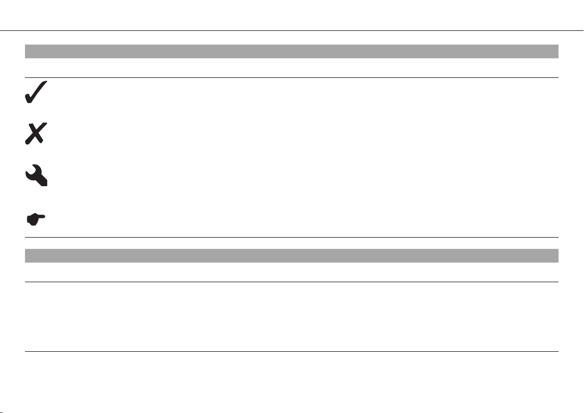
Symbols used
The meaning of specific symbols is described below.
Indicates an expected reaction (e.g. of a work step or a function).
Indicates an unexpected reaction (e.g. of a work step or a function).
All work marked with this symbol requires specialist knowledge and technical understanding. In the interest of your
own safety, have these jobs performed by an authorized KTM workshop! There, your motorcycle will be serviced opti-
mally by specially trained experts using the specialist tools required.
Indicates a page reference (more information is provided on the specified page).
Formats used
The typographical formats used in this document are explained below.
Specific name Identifies a proprietary name.
Name
®
Identifies a protected name.
Brand™ Identifies a brand available on the open market.
IMPORTANT INFORMATION 7
Use definition
KTM sport motorcycles are designed and constructed to meet the normal demands of regular road operation but not for use on race
courses or offroad.
Info
The motorcycle is authorized for public road traffic in the homologous version only.
Service
A prerequisite for fault-free operation and avoiding premature wear is compliance with the instructions for maintenance, care and tuning of
the engine and suspension provided in the owner's manual. Poor adjustment and tuning of the engine and chassis can lead to damage and
breakage of components.
Using the motorcycle in extreme conditions such as very dirty or wet roads can lead to above-average wear of components such as the
transmission train or the brakes. For this reason, it may be necessary to service or replace worn parts before the limit specified in the
service schedule is reached.
It is imperative that you adhere to the stipulated run-in times and service intervals. If you observe these exactly, you will ensure a much
longer service life for your motorcycle.
Warranty
The work prescribed in the service schedule must be carried out by an authorized KTM workshop only and confirmed in the customer's
service record and in the KTM dealer.net; otherwise, all warranty claims will be void. No warranty claims can be considered for damage
resulting from manipulations and/or alterations to the vehicle.
Fuel, oils, etc.
Use the fuels and operating fluids as specified in the Owner's Manual.

IMPORTANT INFORMATION 8
Spare parts, accessories
For your own safety, only use spare parts and accessory products that have been approved and/or recommended by KTM and have them
installed by an authorized KTM workshop. KTM accepts no liability for other products and any resulting damage.
Some spare parts and accessory products are specified in parentheses in the descriptions. Your KTM dealer will be glad to advise you.
You will find the current KTM PowerParts for your vehicle on the KTM website.
International KTM Website: http://www.ktm.com
Work rules
Special tools are necessary for certain tasks. The tools are not contained in the vehicle but can be ordered under the number in parenthe-
ses. Example: valve spring mounter (59029019000)
During assembly, non-reusable parts (e.g. self-locking screws and nuts, seals and seal rings, O-rings, pins, lock washers) must be replaced
by new parts.
If a thread lock (e.g. Loctite
®
) is used for screw connections, be sure to comply with the manufacturer's specific instructions on its usage.
Parts that you want to reuse following repairs and servicing should be cleaned and checked for damage and wear. Change damaged or
worn parts.
Ensure that the vehicle is roadworthy after completing repair and maintenance work.
Transport
Note
Danger of damage The parked vehicle may roll away or fall over.
– Always place the vehicle on a firm and even surface.
Note
Fire hazard Some vehicle components become very hot when the vehicle is operated.
– Do not park the vehicle near flammable or explosive substances. Do not place objects on the vehicle while it is still warm from being
run. Always let the vehicle cool first.
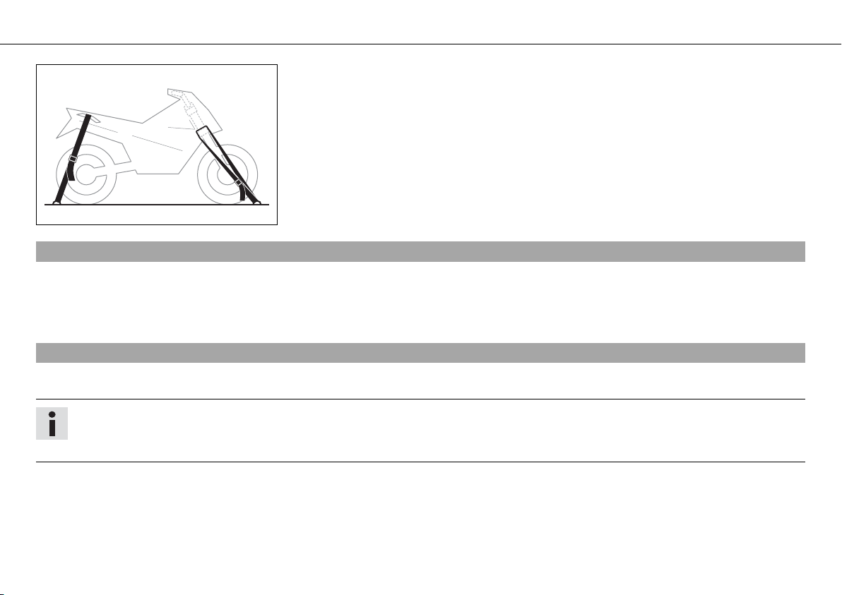
IMPORTANT INFORMATION 9
401448-01
– Switch off the engine and remove the ignition key.
– Use straps or other suitable devices to secure the motorcycle against accidents or
falling over.
Environment
Offroad motorcycling is a wonderful sport and we naturally hope that you will be able to enjoy it to the fullest. However, it is a potential
problem for the environment and can lead to conflicts with other persons. But if you use your motorcycle responsibly, you can ensure that
such problems and conflicts do not have to occur. To protect the future of motorcycle sport, make sure that you use your motorcycle
legally, display environmental consciousness, and respect the rights of others.
Notes/warnings
Pay close attention to the notes/warnings.
Info
Various information and warning labels are affixed to the vehicle. Do not remove information/warning labels. If they are missing,
you or others may not recognize potential hazards and may therefore be injured.
IMPORTANT INFORMATION 10
Grades of risks
Danger
Identifies a danger that will immediately and invariably lead to fatal or serious permanent injury if the appropriate measures are not
taken.
Warning
Identifies a danger that is likely to lead to fatal or serious injury if the appropriate measures are not taken.
Caution
Identifies a danger that may lead to minor injuries if the appropriate measures are not taken.
Note
Identifies a danger that will lead to considerable machine and material damage if the appropriate measures are not taken.
Warning
Identifies a danger that will lead to environmental damage if the appropriate measures are not taken.
Owner's manual
– It is important that you read this owner's manual carefully and completely before making your first trip. It contains useful information
and tips to help you operate and handle your motorcycle. Only then will you find out how to customize the motorcycle ideally for your
own use and how you can protect yourself from injury. The owner's manual also contains important information on servicing the motor-
cycle.
– The owner's manual is an important component of the motorcycle and should be handed over to the new owner if the vehicle is sold.

11
VIEW OF VEHICLE 12
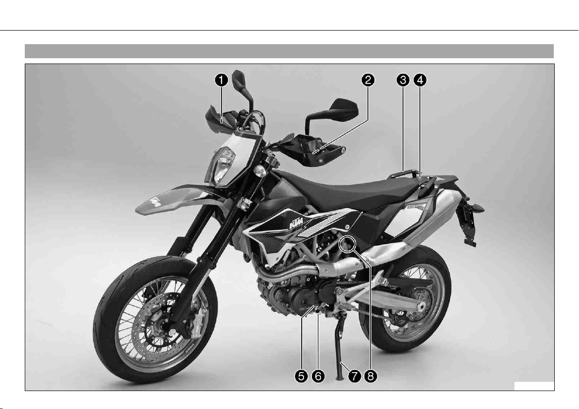
3.1View of vehicle, front left side (example)
601816-10
VIEW OF VEHICLE 13
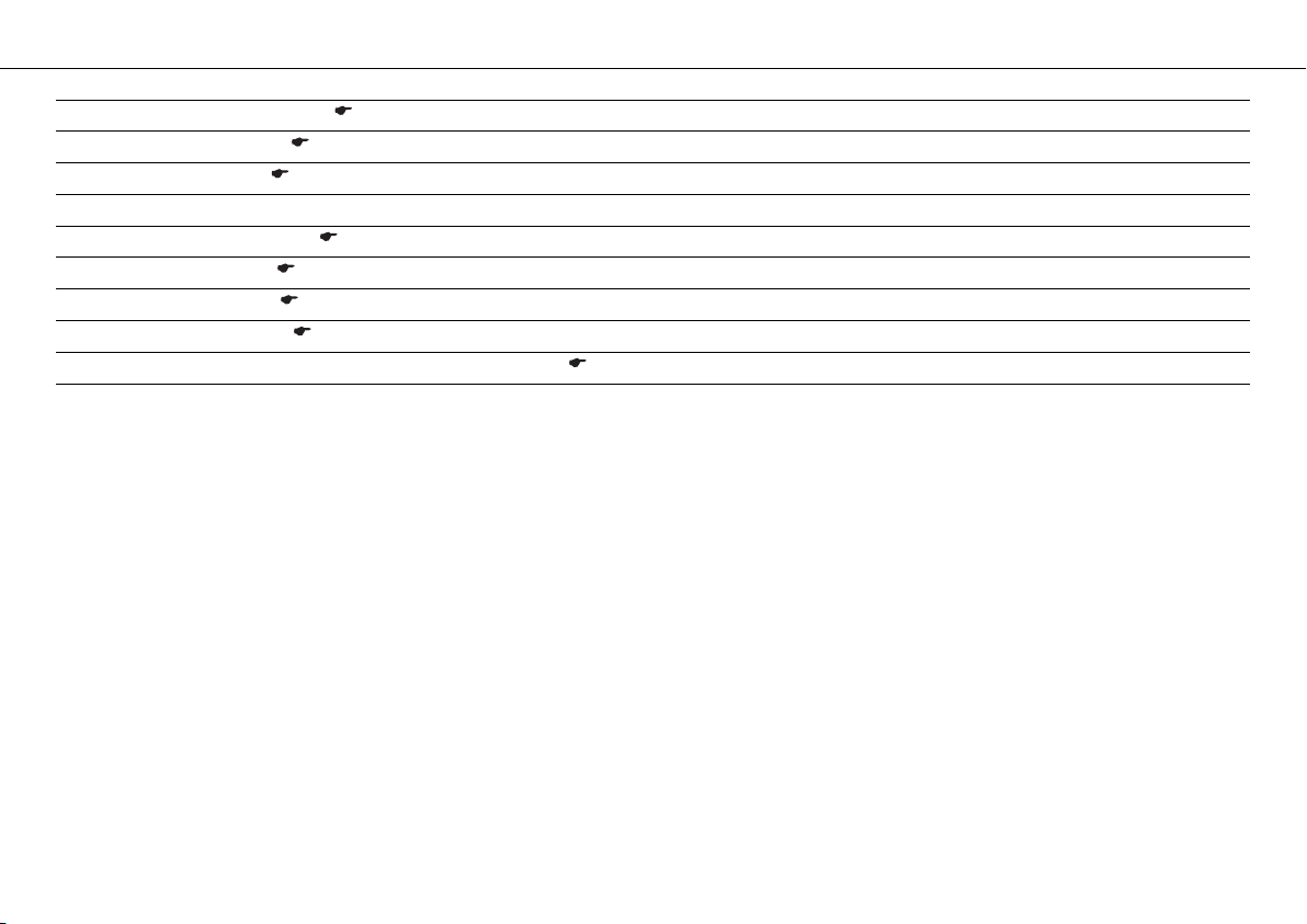
1 Hand brake lever ( p. 19)
2 Clutch lever ( p. 19)
3 Handrails ( p. 34)
4 Filler cap
5 Engine number ( p. 17)
6 Shift lever ( p. 35)
7 Side stand ( p. 36)
8 Seat release ( p. 33)
8 Compression damping of the shock absorber ( p. 58)

VIEW OF VEHICLE 14
3.2View of vehicle, rear right side (example)
601817-10
VIEW OF VEHICLE 15
1 Light switch ( p. 20)
1 Turn signal switch ( p. 21)
1 Horn button ( p. 21)
2 Ignition/steering lock ( p. 23)
3 Combination instrument ( p. 23)
4 Emergency OFF switch ( p. 22)
4 Electric starter button ( p. 22)
5 Throttle grip ( p. 20)
6 Shock absorber, rebound adjustment
7 Foot brake lever ( p. 36)
8 Level viewer, engine oil
9 Type label ( p. 16)
10 Chassis number ( p. 16)

SERIAL NUMBERS 16
4.1Chassis number
601858-10
The chassis number 1 is stamped on the steering head on the right.
4.2Type label
601859-10
The type label 1 is located on the right side of the frame.
SERIAL NUMBERS 17
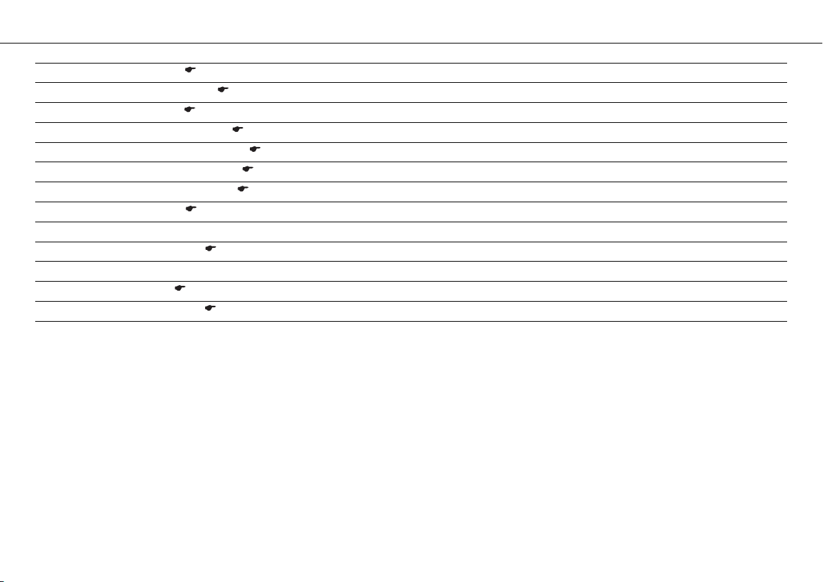
4.3Engine number
601860-10
The engine number 1 is stamped on the left side of the engine under the engine sprocket.
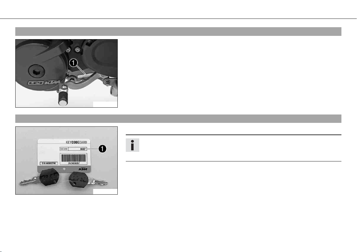
4.4Key number
100179-10
The key number 1 can be found on the KEYCODECARD.
Info
You need the key number to order a spare key. Keep the KEYCODECARD in a safe
place.
SERIAL NUMBERS 18
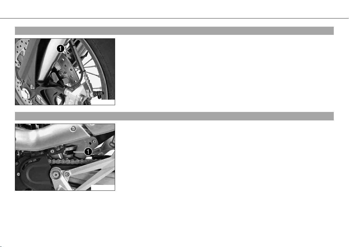
4.5Fork part number
601861-10
The fork part number 1 is stamped on the inner side of the fork stub.
4.6Shock absorber part number
601862-10
The shock absorber part number 1 is on the left of the shock absorber.
CONTROLS 19
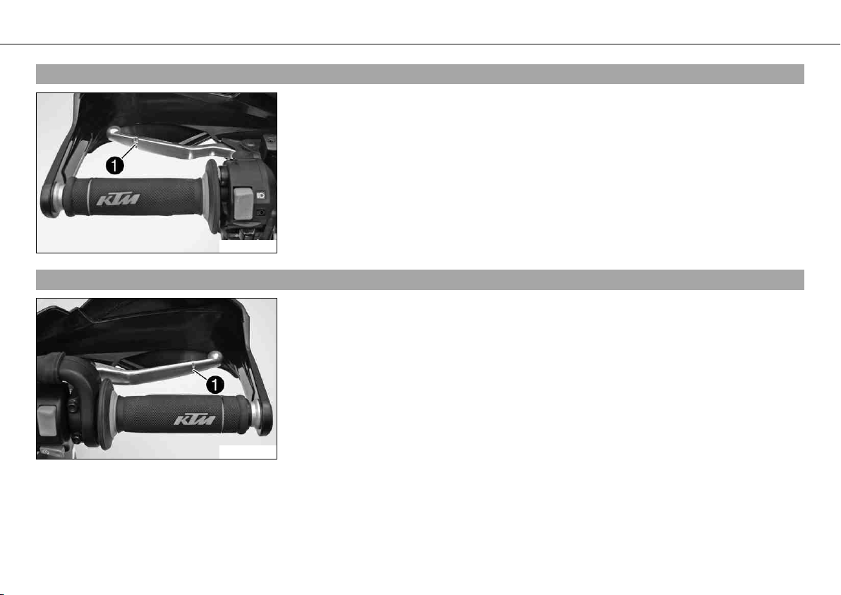
5.1Clutch lever
601863-10
The clutch lever 1 is fitted on the left side of the handlebar.
The clutch is hydraulically operated and self-adjusting.
5.2Hand brake lever
601864-10
The hand break lever 1 is fitted on the right side of the handlebar.
The hand brake lever operates the front brake.
CONTROLS 20
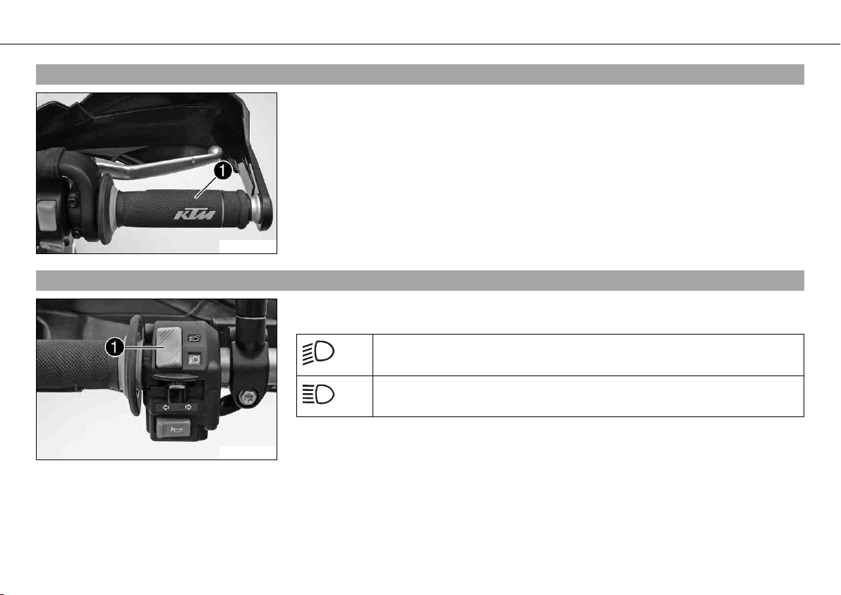
5.3Throttle grip
601864-11
The throttle grip 1 is fitted on the right side of the handlebar.
5.4Light switch
601865-10
The light switch 1 is fitted on the left side of the handlebar.
Possible states
Low beam on – Light switch is turned downwards. In this position, the low
beam and tail light are switched on.
High beam on – Light switch is turned upwards. In this position, the high
beam and the tail light are switched on.
CONTROLS 21
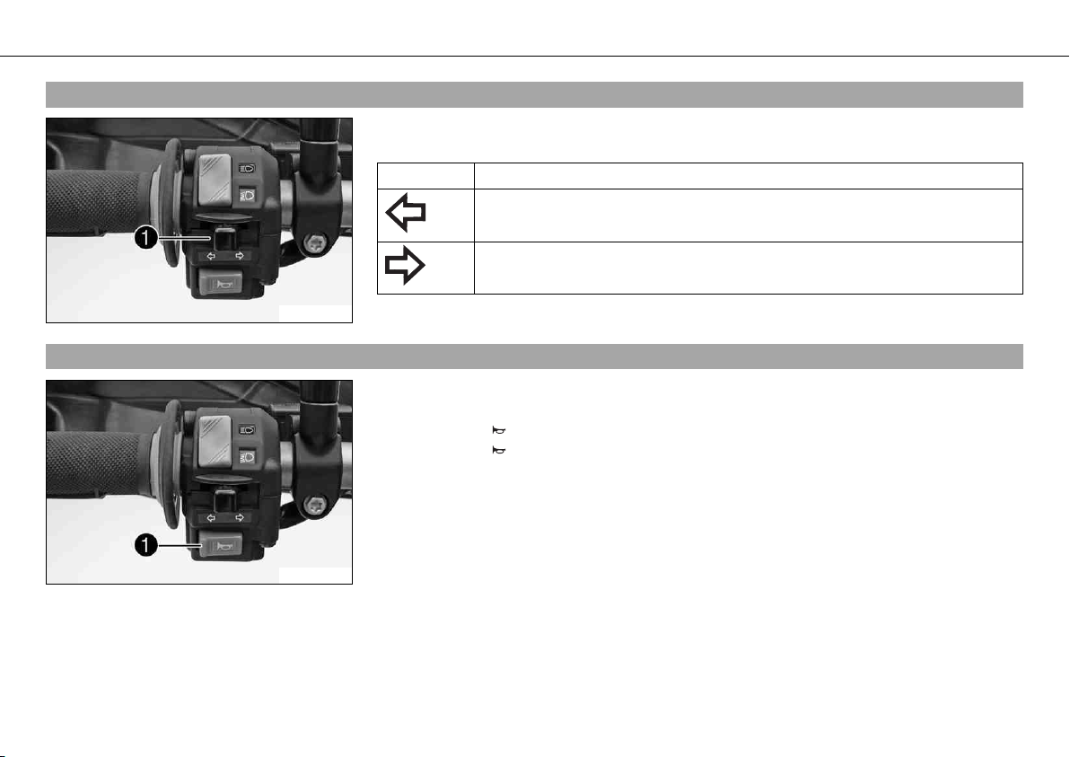
5.5Turn signal switch
601865-11
The turn signal switch 1 is fitted on the left side of the handlebar.
Possible states
Turn signal off
Turn signal light, left, on – Turn signal switch pressed to the left. The turn
signal switch returns automatically to the central position after use.
Turn signal light, right, on – Turn signal switch pressed to the right. The
turn signal switch returns automatically to the central position after use.
To switch off the turn signal light, press the turn signal switch towards the switch case.
5.6Horn button
601865-12
The horn button 1 is fitted on the left side of the handlebar.
Possible states
• Horn button in neutral position
• Horn button pressed – The horn is operated in this position.
CONTROLS 22
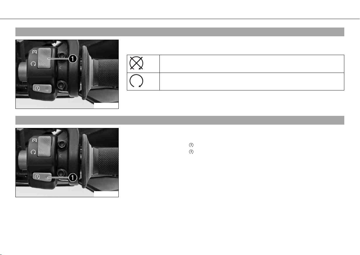
5.7Emergency OFF switch
601866-10
The emergency OFF switch 1 is fitted on the right side of the handlebar.
Possible states
Emergency OFF switch off – In this position, the ignition circuit is inter-
rupted, a running engine stops, and the engine cannot be started.
Emergency OFF switch on – This position is necessary for operation as the
ignition circuit is closed.
5.8Electric starter button
601866-11
The electric starter button 1 is fitted on the right side of the handlebar.
Possible states
• Electric starter button in basic position
• Electric starter button pressed – In this position, the electric starter is actuated.
CONTROLS 23
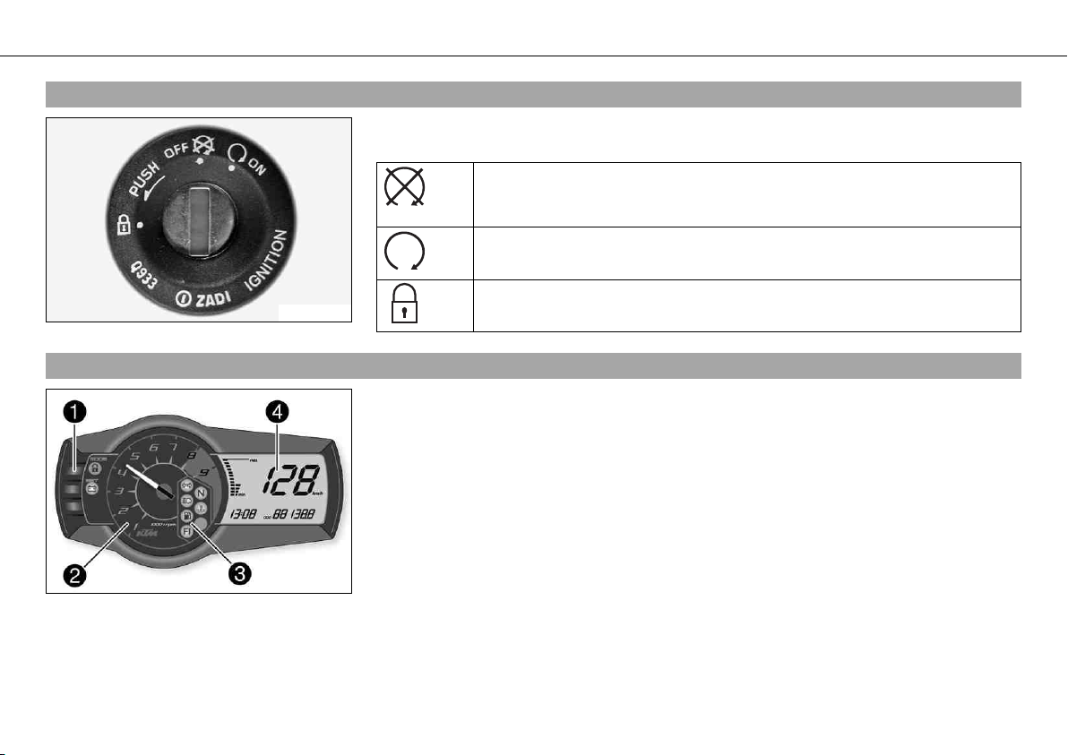
5.9Ignition/steering lock
600825-01
The ignition/steering lock 1 is located in front of the seat.
Possible states
Ignition OFF – In this position, the ignition circuit is interrupted, a running
engine stops, and a non-running engine will not start. The ignition key can
be removed.
Ignition ON – In this position, the ignition circuit is closed and the engine
can be started.
Steering locked – In this position, the ignition circuit is interrupted and the
steering locked. The ignition key can be removed.
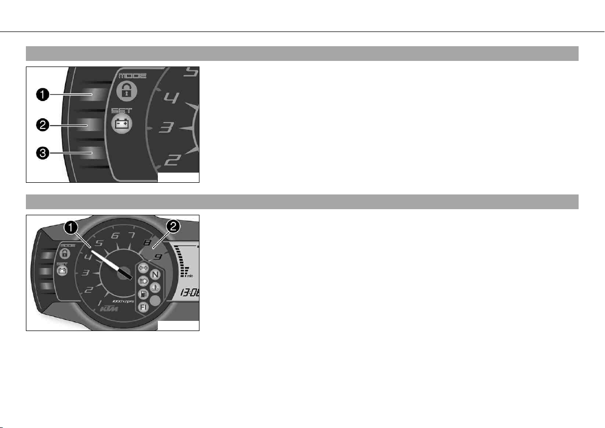
5.10Combination instrument
400832-10
The combination instrument is installed in front of the handlebar.
The combination instrument is divided into 4 function areas.
1 Function buttons
2 Tachometer
3 Indicator lights
4 Display
CONTROLS 24
5.11Combination instrument - function buttons
400833-10
You can change the display mode with the MODE button 1.
Possible display modes are distance traveled (ODO), trip master 1 (TRIP 1) and trip mas-
ter 2 (TRIP 2).
Press the SET button 2 to reset the trip master 1 function (TRIP 1) and trip master 2 func-
tion (TRIP 2) to 0.0.
Button 3 has no function.
5.12Combination instrument - tachometer
400834-10
The tachometer 1 shows the engine speed in revolutions per minute.
The red marking 2 shows the excess speed range of the engine.
CONTROLS 25
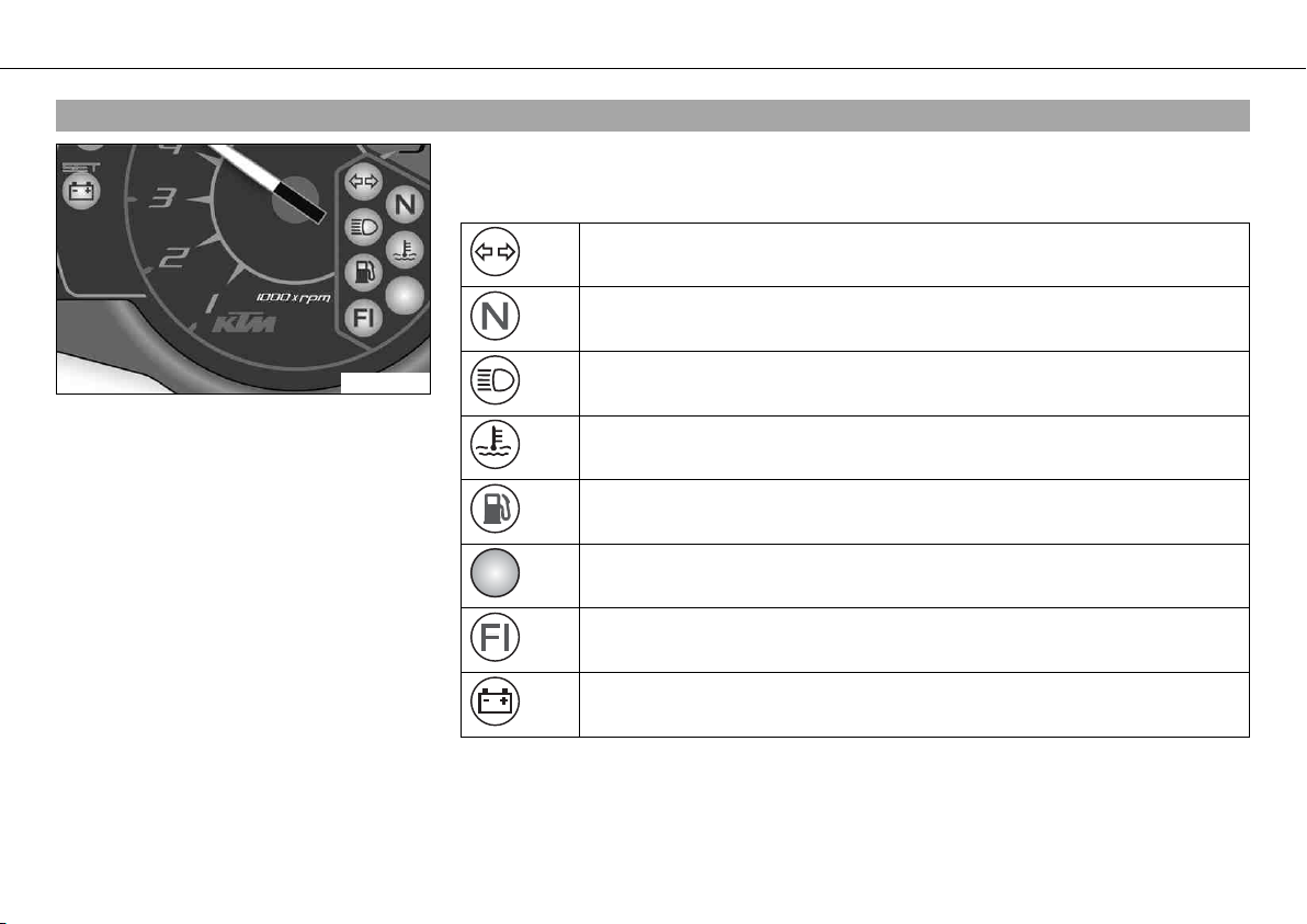
5.13Combination instrument - indicator lamps
401440-01
The indicator lamps offer additional information about the operating state of the motorcy-
cle.
Possible states
The turn signal indicator lamp flashes green simultaneously with the turn
signal – The turn signal is switched on.
The idle speed indicator lamp lights up green – The transmission is shifted
to idle.
The high beam indicator lamp lights up blue – The high beam is switched
on.
The temperature warning lamp lights up red – The coolant temperature has
reached a critical value.
The fuel level warning lamp lights up orange – The fuel level has reached
the reserve mark. The display switches to TRIP F.
The oil pressure warning lamp lights up red – The oil pressure is too low.
FI warning lamp (MIL) lights up/flashes orange – The OBD (on-board diagno-
sis) has detected an emission- or safety-critical error.
The battery warning lamp lights up red – The voltage in the vehicle system
is too low.
CONTROLS 26
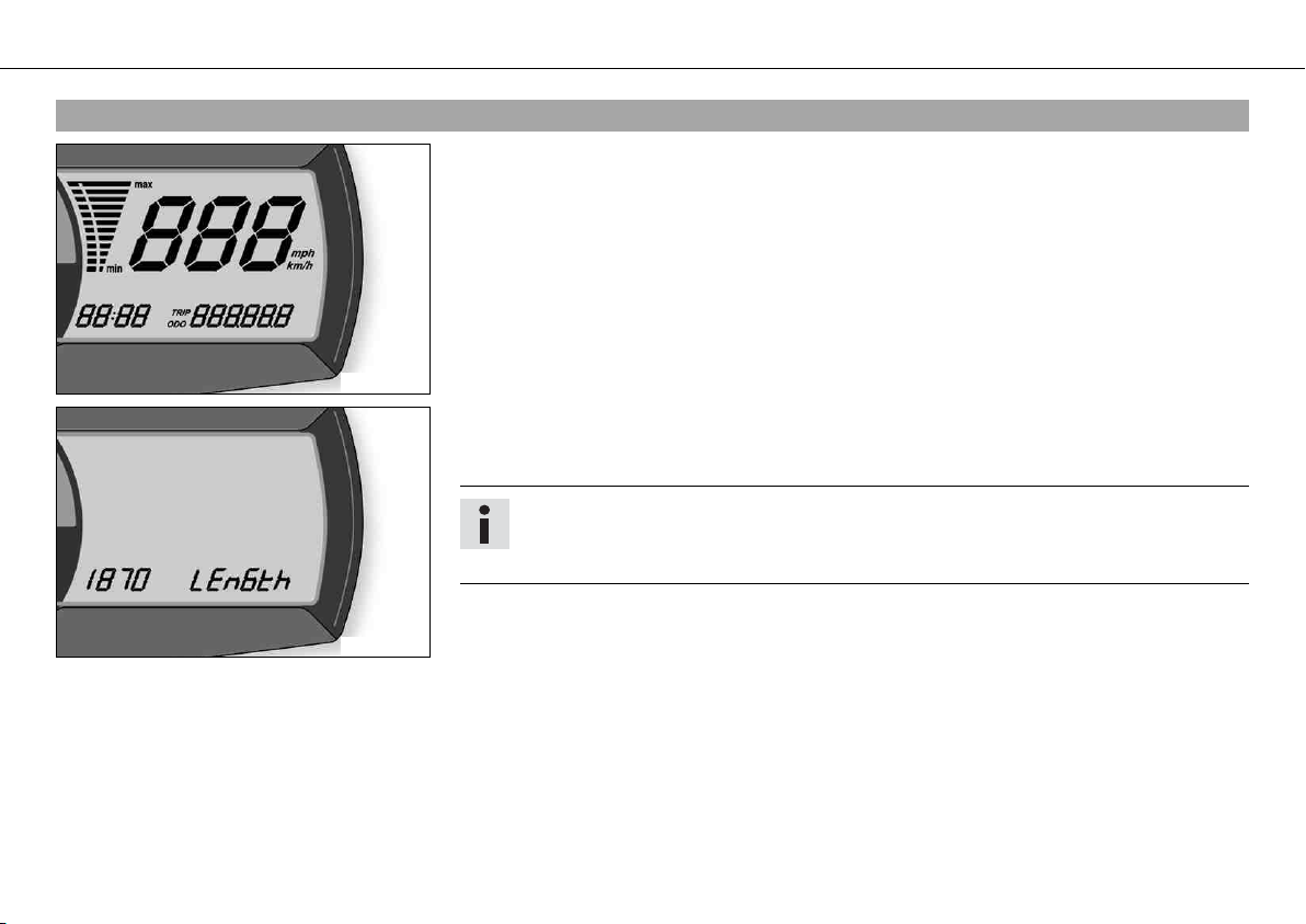
5.14Combination instrument - display
400836-01
When you switch on the ignition, all display segments light up for a second as a function
test.
400881-01
LEnGth
Following the display function test, the LEnGth wheel circumference is shown for one sec-
ond.
Info
1870 mm corresponds to the circumference of the 17" front wheel with a series pro-
duction tire.
The display then changes to the last selected mode.
CONTROLS 27
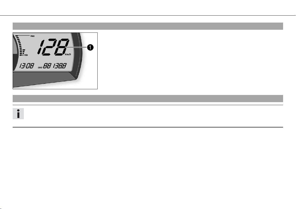
5.15Combination instrument - speedometer
400838-10
The speed 1 is shown in kilometers per hour km/h or in miles per hour mph.
5.16Setting kilometers or miles
Info
If you change the unit, the value ODO is retained and converted accordingly.
Making the setting according to the country.
Condition
The motorcycle is stationary.
CONTROLS 28
400839-01
– Switch on the ignition by turning the ignition key to position ON .
– Press the MODE button repeatedly until the ODO mode is active.
– Keep the MODE button pressed until the display mode changes from km/h to mph or
from mph to km/h.
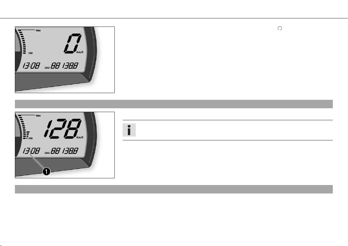
5.17Combination instrument - time
400838-11
The time is shown in area 1 of the display.
Info
After reconnecting the battery or changing the fuse, the time must be reset.
5.18Setting the clock
Condition
The motorcycle is stationary.
Loading...