


 Loading...
REPAIR MANUAL 2013
125 Duke EU
200 Duke EU
200 Duke MAL
200 Duke 2014 COL
Art. no. 3206162en

INTRODUCTION |
1 |
It is important that you read this repair manual carefully and completely before the start of work.
This vehicle can only fulfill the demands placed on it in the long run if the specified service work is performed regularly by qualified experts.
The repair manual was written to correspond to the most current state of this model series. We reserve the right to make changes in the interest of technical advancement without, at the same time, updating this repair manual.
We shall not provide a description of general workshop methods. Likewise, safety rules that apply in a workshop are not specified here. It is assumed that repair work will be performed by a fully trained mechanic.
All specifications are non-binding. KTM Sportmotorcycle AG specifically reserves the right to modify or delete technical specifications, prices, colors, forms, materials, services, designs, equipment, etc., without prior notice and without specifying reasons, to adapt these to local conditions, as well as to stop production of a particular model without prior notice. KTM accepts no liability for delivery options, deviations from illustrations and descriptions, as well as misprints and other errors. The models portrayed partly contain special equipment that does not belong to the regular scope of supply.
© 2013 KTM-Sportmotorcycle AG, Mattighofen Austria All rights reserved
Reproduction, even in part, as well as copying of all kinds, is permitted only with the express written permission of the copyright owner.
ISO 9001(12 100 6061)
According to the international quality management standard ISO 9001, KTM uses quality assurance processes that lead to the maximum possible quality of the products.
Issued by: TÜV Management Service
KTM-Sportmotorcycle AG
5230 Mattighofen, Austria
TABLE OF CONTENTS |
2 |
1 |
MEANS OF REPRESENTATION ..................................... |
6 |
|
|
1.1 |
Symbols used ................................................... |
6 |
|
1.2 |
Formats used.................................................... |
6 |
2 |
SAFETY ADVICE........................................................... |
7 |
|
|
2.1 |
Repair Manual .................................................. |
7 |
|
2.2 |
Safety advice.................................................... |
7 |
|
2.3 |
Degrees of risk and symbols ............................... |
7 |
|
2.4 |
Work rules........................................................ |
7 |
3 |
IMPORTANT INFORMATION ......................................... |
8 |
|
|
3.1 |
Guarantee, warranty .......................................... |
8 |
|
3.2 |
Operating and auxiliary substances ..................... |
8 |
|
3.3 |
Spare parts, accessories .................................... |
8 |
|
3.4 |
Figures ............................................................ |
8 |
4 |
SERIAL NUMBERS ...................................................... |
9 |
|
|
4.1 |
Chassis number/type label ................................. |
9 |
|
4.2 |
Key number...................................................... |
9 |
|
4.3 |
Engine number ................................................. |
9 |
5 |
MOTORCYCLE ........................................................... |
10 |
|
5.1Raising the motorcycle with the rear wheel
stand ............................................................. |
10 |
5.2Taking the motorcycle off of the rear wheel
stand ............................................................. |
10 |
5.3Raising the motorcycle with the front wheel
stand ............................................................. |
10 |
5.4Taking the motorcycle off of the front wheel
|
|
stand ............................................................. |
11 |
|
5.5 |
Raising the motorcycle with the work stand ....... |
11 |
|
5.6 |
Removing the motorcycle from the work stand ... |
12 |
|
5.7 |
Starting.......................................................... |
13 |
|
5.8 |
Starting the motorcycle to make checks ............ |
14 |
6 |
FORK, TRIPLE CLAMP ............................................... |
15 |
|
|
6.1 |
Cleaning the dust boots of the fork legs............. |
15 |
|
6.2 |
Removing fork legs.......................................... |
15 |
|
6.3 |
Installing the fork legs..................................... |
17 |
|
6.4 |
Disassembling the fork legs.............................. |
20 |
|
6.5 |
Checking the fork legs ..................................... |
22 |
|
6.6 |
Assembling the fork legs.................................. |
23 |
|
6.7 |
Removing the lower triple clamp....................... |
24 |
|
6.8 |
Installing the lower triple clamp ....................... |
27 |
|
6.9 |
Checking the steering head bearing play............ |
29 |
|
6.10 |
Adjusting the steering head bearing play ........... |
30 |
7 |
HANDLEBAR, CONTROLS........................................... |
32 |
|
|
7.1 |
Checking the play in the throttle cable .............. |
32 |
|
7.2 |
Adjusting the play in the throttle cable.............. |
32 |
|
7.3 |
Checking the clutch lever play.......................... |
32 |
|
7.4 |
Adjusting the clutch cable play ........................ |
33 |
8 |
SHOCK ABSORBER, SWINGARM ................................ |
34 |
|
8.1Adjusting the spring preload of the shock
|
|
absorber......................................................... |
34 |
|
8.2 |
Removing the shock absorber........................... |
34 |
|
8.3 |
Installing the shock absorber............................ |
35 |
|
8.4 |
Removing the spring........................................ |
36 |
|
8.5 |
Installing the spring ........................................ |
36 |
9 |
EXHAUST.................................................................. |
38 |
|
|
9.1 |
Removing the exhaust manifold........................ |
38 |
|
9.2 |
Installing the exhaust manifold ........................ |
39 |
|
9.3 |
Removing the main silencer ............................. |
40 |
|
9.4 |
Installing the main silencer.............................. |
42 |
10 |
AIR FILTER ............................................................... |
44 |
|
|
10.1 |
Removing the air filter..................................... |
44 |
|
10.2 |
Installing the air filter...................................... |
44 |
11 FUEL TANK, SEAT, TRIM ........................................... |
45 |
|
11.1 |
Opening the filler cap...................................... |
45 |
11.2 |
Closing the filler cap ....................................... |
45 |
11.3 |
Removing the seat .......................................... |
45 |
11.4 |
Mounting the seat ........................................... |
46 |
11.5 |
Removing the passenger seat ........................... |
46 |
11.6 |
Mounting the passenger seat............................ |
46 |
11.7 |
Removing the fuel tank cover ........................... |
46 |
11.8 |
Installing the fuel tank cover............................ |
49 |
11.9 |
Removing the fuel tank.................................... |
51 |
11.10 |
Installing the fuel tank .................................... |
53 |
11.11 |
Removing the front spoiler ............................... |
54 |
11.12 |
Fitting front spoiler ......................................... |
54 |
11.13 |
Dismounting the front fender ........................... |
55 |
11.14 |
Installing the front fender ................................ |
55 |
11.15 |
Checking the fuel pressure............................... |
56 |
11.16 |
Changing the fuel filter.................................... |
57 |
11.17 |
Replacing the fuel pump ................................. |
58 |
12 WHEELS ................................................................... |
60 |
|
12.1 |
Checking the tire air pressure........................... |
60 |
12.2 |
Checking the tire condition .............................. |
60 |
12.3 |
Checking the brake discs ................................. |
61 |
12.4 |
Front wheel .................................................... |
61 |
12.4.1 |
Removing the front wheel ............................ |
61 |
12.4.2 |
Installing the front wheel ............................. |
62 |
12.4.3 |
Removing the brake disc of the front brake.... |
63 |
12.4.4 |
Installing the brake disc of the front brake .... |
64 |
12.5 |
Rear wheel ..................................................... |
64 |
12.5.1 |
Removing the rear wheel ............................. |
64 |
12.5.2 |
Installing the rear wheel .............................. |
65 |
12.5.3 |
Removing the brake disc of the rear brake..... |
66 |
12.5.4 |
Installing the brake disc of the rear brake...... |
67 |
12.5.5 |
Checking the chain tension.......................... |
68 |
12.5.6 |
Adjusting the chain tension ......................... |
68 |
12.5.7Checking the chain, rear sprocket, and
|
engine sprocket .......................................... |
69 |
12.5.8 |
Cleaning the chain ...................................... |
72 |
12.5.9 Checking the rear hub rubber dampers.......... |
73 |
|
13 WIRING HARNESS, BATTERY..................................... |
74 |
|
13.1 |
Removing the battery ...................................... |
74 |
13.2 |
Installing the battery ....................................... |
74 |
13.3Disconnecting the negative cable of the
battery ........................................................... |
75 |
13.4Reconnecting the negative cable of the
|
battery ........................................................... |
75 |
13.5 |
Recharging the battery .................................... |
75 |
13.6 |
Checking the charging voltage .......................... |
76 |
13.7Changing the fuses of individual power
|
consumers...................................................... |
77 |
14 BRAKE SYSTEM ........................................................ |
79 |
|
14.1 |
Checking the front brake linings ....................... |
79 |
14.2 |
Changing the front brake linings ....................... |
79 |
14.3Checking the brake fluid level of the front
|
brake ............................................................. |
82 |
14.4 |
Adding front brake fluid................................... |
83 |
14.5 |
Changing the front brake fluid.......................... |
83 |
14.6 |
Checking the rear brake linings ........................ |
86 |
14.7 |
Changing the rear brake linings ........................ |
86 |
14.8 |
Checking the free travel of foot brake lever ........ |
89 |
14.9Adjusting the free travel of the foot brake
lever .............................................................. |
89 |
14.10 Checking the rear brake fluid level.................... |
90 |
TABLE OF CONTENTS
|
14.11 |
Adding rear brake fluid .................................... |
90 |
|
14.12 |
Changing the rear brake fluid ........................... |
91 |
15 |
LIGHTING SYSTEM, INSTRUMENTS ........................... |
94 |
|
|
15.1 |
Setting kilometers or miles............................... |
94 |
|
15.2 |
Adjusting the shift speed RPM 1 ...................... |
94 |
|
15.3 |
Adjusting the shift speed RPM 2 ...................... |
94 |
|
15.4 |
Setting the time.............................................. |
95 |
|
15.5 |
Resetting the service interval display ................ |
95 |
|
15.6 |
Checking the headlight setting ......................... |
95 |
|
15.7 |
Adjusting the headlight range........................... |
96 |
|
15.8 |
Changing the parking light bulb........................ |
97 |
|
15.9 |
Changing the headlight bulb ............................ |
98 |
16 |
ENGINE .................................................................. |
100 |
|
|
16.1 |
Removing the engine..................................... |
100 |
|
16.2 |
Installing the engine...................................... |
103 |
|
16.3 |
Engine disassembly....................................... |
108 |
|
16.3.1 |
Preparations (125 Duke) ........................... |
108 |
|
16.3.2 Draining the engine oil (125 Duke)............. |
108 |
|
16.3.3Removing the chain securing guide (125
|
Duke) ...................................................... |
109 |
16.3.4 |
Removing the valve cover (125 Duke) ......... |
109 |
16.3.5 |
Removing the spark plug (125 Duke).......... |
109 |
16.3.6 |
Removing the clutch cover (125 Duke) ....... |
109 |
16.3.7Setting the engine to ignition top dead
center (125 Duke) .................................... |
110 |
16.3.8 Removing the starter motor (125 Duke) ...... |
110 |
16.3.9Removing the timing chain tensioner (125
|
Duke) ...................................................... |
111 |
16.3.10 Removing the camshaft (125 Duke)............ |
111 |
|
16.3.11 |
Removing the cylinder head (125 Duke) ..... |
112 |
16.3.12 |
Removing the piston (125 Duke)................ |
112 |
16.3.13Removing the water pump wheel (125
Duke) ...................................................... |
113 |
16.3.14Removing the alternator cover (125
|
Duke) ...................................................... |
114 |
16.3.15 |
Removing the rotor (125 Duke) .................. |
114 |
16.3.16 |
Removing the starter drive (125 Duke)........ |
115 |
16.3.17Removing the balancer shaft drive wheel
(125 Duke) .............................................. |
115 |
16.3.18Removing the gear position sensor (125
Duke) ...................................................... |
116 |
16.3.19 Removing the spacer (125 Duke) ............... |
117 |
16.3.20 Removing the clutch basket (125 Duke) ..... |
117 |
16.3.21 Removing the primary gear (125 Duke)....... |
118 |
16.3.22 Removing the oil pump (125 Duke) ............ |
118 |
16.3.23 Removing the shift shaft (125 Duke) .......... |
119 |
16.3.24Removing the shift drum locating (125
|
Duke) ...................................................... |
119 |
16.3.25 |
Removing the locking lever (125 Duke)....... |
119 |
16.3.26 |
Removing the oil filter (125 Duke) ............. |
119 |
16.3.27Removing the left engine case (125
|
Duke) ...................................................... |
120 |
16.3.28 Removing the shift rails (125 Duke) ........... |
121 |
|
16.3.29 |
Removing the shift drum (125 Duke).......... |
121 |
16.3.30 |
Removing the shift forks (125 Duke) .......... |
121 |
16.3.31Removing the transmission shafts (125
|
Duke) ...................................................... |
121 |
16.3.32 Removing the balancer shaft (125 Duke) .... |
122 |
|
16.3.33 Removing the crankshaft (125 Duke).......... |
122 |
|
16.3.34 |
Preparations (200 Duke) ........................... |
122 |
16.3.35 |
Draining the engine oil (200 Duke)............. |
122 |
16.3.36Removing the chain securing guide (200
Duke) ...................................................... |
123 |
|
|
3 |
16.3.37 Removing the valve cover (200 Duke) ......... |
123 |
|
16.3.38 |
Removing the spark plug (200 Duke).......... |
123 |
16.3.39 |
Removing the clutch cover (200 Duke) ....... |
123 |
16.3.40Setting the engine to ignition top dead
center (200 Duke) .................................... |
124 |
16.3.41 Removing the starter motor (200 Duke) ...... |
124 |
16.3.42Removing the timing chain tensioner (200
|
Duke) ...................................................... |
125 |
16.3.43 Removing the camshaft (200 Duke)............ |
125 |
|
16.3.44 |
Removing the cylinder head (200 Duke) ..... |
126 |
16.3.45 |
Removing the piston (200 Duke)................ |
126 |
16.3.46Removing the water pump wheel (200
Duke) ...................................................... |
127 |
16.3.47Removing the alternator cover (200
|
Duke) ...................................................... |
128 |
16.3.48 |
Removing the rotor (200 Duke) .................. |
128 |
16.3.49 |
Removing the starter drive (200 Duke)........ |
129 |
16.3.50Removing the balancer shaft drive wheel
(200 Duke) .............................................. |
129 |
16.3.51Removing the gear position sensor (200
Duke) ...................................................... |
130 |
16.3.52 Removing the spacer (200 Duke) ............... |
131 |
16.3.53 Removing the clutch basket (200 Duke) ..... |
131 |
16.3.54 Removing the primary gear (200 Duke)....... |
132 |
16.3.55 Removing the oil pump (200 Duke) ............ |
132 |
16.3.56 Removing the shift shaft (200 Duke) .......... |
133 |
16.3.57Removing the shift drum locating (200
|
Duke) ...................................................... |
133 |
16.3.58 |
Removing the locking lever (200 Duke)....... |
133 |
16.3.59 |
Removing the oil filter (200 Duke) ............. |
133 |
16.3.60Removing the left engine case (200
|
Duke) ...................................................... |
134 |
16.3.61 Removing the shift rails (200 Duke) ........... |
135 |
|
16.3.62 |
Removing the shift drum (200 Duke).......... |
135 |
16.3.63 |
Removing the shift forks (200 Duke) .......... |
135 |
16.3.64Removing the transmission shafts (200
|
Duke) ...................................................... |
135 |
16.3.65 |
Removing the balancer shaft (200 Duke) .... |
136 |
16.3.66 |
Removing the crankshaft (200 Duke).......... |
136 |
16.4 Work on individual parts ................................ |
136 |
|
16.4.1Work on the left section of the engine case
(125 Duke) .............................................. |
136 |
16.4.2Work on the right section of the engine
case (125 Duke)....................................... |
137 |
16.4.3Changing the shaft seal ring of the water
pump (125 Duke) ..................................... |
137 |
16.4.4 Removing the main bearing (125 Duke) ...... |
138 |
16.4.5Checking the radial play of the lower
|
conrod bearing (125 Duke) ........................ |
139 |
16.4.6 |
Changing the conrod bearing (125 Duke) .... |
140 |
16.4.7Changing the balancer shaft bearing (125
Duke) ...................................................... |
141 |
16.4.8Changing the camshaft bearing (125
|
Duke) ...................................................... |
141 |
16.4.9 |
Work on the cylinder head (125 Duke)........ |
142 |
16.4.10 |
Checking the cylinder head (125 Duke) ...... |
143 |
16.4.11Checking/measuring the cylinder (125
Duke) ...................................................... |
143 |
16.4.12Checking the piston ring end gap (125
Duke) ...................................................... |
144 |
16.4.13Checking/measuring the piston (125
Duke) ...................................................... |
144 |
16.4.14Checking the piston/cylinder mounting
clearance (125 Duke)................................ |
145 |
TABLE OF CONTENTS
16.4.15 Checking the oil pump (125 Duke)............. |
145 |
16.4.16Checking the oil pressure regulator valve
(125 Duke) .............................................. |
145 |
16.4.17 Checking the clutch (125 Duke)................. |
146 |
16.4.18 Preassembling the clutch (125 Duke) ......... |
147 |
16.4.19 Checking the shift mechanism (125 |
|
Duke) ...................................................... |
148 |
16.4.20 Preassembling the shift shaft (125 Duke) ... |
149 |
16.4.21Disassembling the main shaft (125
|
Duke) ...................................................... |
149 |
16.4.22 Dismantling the countershaft (125 Duke).... |
150 |
|
16.4.23 Checking the transmission (125 Duke)........ |
150 |
|
16.4.24 |
Assembling the main shaft (125 Duke) ....... |
151 |
16.4.25 |
Assembling the countershaft (125 Duke) .... |
152 |
16.4.26Checking the timing assembly (125
Duke) ...................................................... |
154 |
16.4.27 Changing the stator (125 Duke) ................. |
154 |
16.4.28Checking the electric starter drive (125
Duke) ...................................................... |
155 |
16.4.29 Checking the freewheel (125 Duke)............ |
156 |
16.4.30Work on the left section of the engine case
(200 Duke) .............................................. |
156 |
16.4.31Work on the right section of the engine
case (200 Duke)....................................... |
157 |
16.4.32Changing the shaft seal ring of the water
|
pump (200 Duke) ..................................... |
157 |
16.4.33 Removing the main bearing (200 Duke) ...... |
158 |
|
16.4.34 |
Checking the radial play of the lower |
|
|
conrod bearing (200 Duke) ........................ |
159 |
16.4.35 |
Changing the conrod bearing (200 Duke) .... |
160 |
16.4.36Changing the balancer shaft bearing (200
Duke) ...................................................... |
161 |
16.4.37Changing the camshaft bearing (200
|
Duke) ...................................................... |
161 |
16.4.38 |
Work on the cylinder head (200 Duke)........ |
162 |
16.4.39 |
Checking the cylinder head (200 Duke) ...... |
163 |
16.4.40Checking/measuring the cylinder (200
Duke) ...................................................... |
163 |
16.4.41Checking the piston ring end gap (200
Duke) ...................................................... |
164 |
16.4.42Checking/measuring the piston (200
Duke) ...................................................... |
164 |
16.4.43Checking the piston/cylinder mounting
clearance (200 Duke)................................ |
165 |
16.4.44 Checking the oil pump (200 Duke)............. |
165 |
16.4.45Checking the oil pressure regulator valve
(200 Duke) .............................................. |
165 |
16.4.46 Checking the clutch (200 Duke)................. |
166 |
16.4.47 Preassembling the clutch (200 Duke) ......... |
167 |
16.4.48 Checking the shift mechanism (200 |
|
Duke) ...................................................... |
168 |
16.4.49 Preassembling the shift shaft (200 Duke) ... |
169 |
16.4.50Disassembling the main shaft (200
|
Duke) ...................................................... |
169 |
16.4.51 Dismantling the countershaft (200 Duke).... |
170 |
|
16.4.52 Checking the transmission (200 Duke)........ |
170 |
|
16.4.53 |
Assembling the main shaft (200 Duke) ....... |
171 |
16.4.54 |
Assembling the countershaft (200 Duke) .... |
172 |
16.4.55Checking the timing assembly (200
Duke) ...................................................... |
174 |
16.4.56 Changing the stator (200 Duke) ................. |
174 |
16.4.57Checking the electric starter drive (200
Duke) ...................................................... |
175 |
16.4.58 Checking the freewheel (200 Duke)............ |
176 |
|
|
4 |
16.5 |
Engine assembly........................................... |
176 |
16.5.1 |
Installing the crankshaft (125 Duke) .......... |
176 |
16.5.2 |
Installing the balancer shaft (125 Duke) ..... |
176 |
16.5.3Installing the transmission shafts (125
|
Duke) ...................................................... |
177 |
16.5.4 Installing the shift forks (125 Duke) ........... |
177 |
|
16.5.5 |
Installing the shift drum (125 Duke)........... |
177 |
16.5.6 |
Installing the shift rails (125 Duke) ............ |
178 |
16.5.7Installing the left engine case (125
|
Duke) ...................................................... |
178 |
16.5.8 |
Installing the oil filter (125 Duke) .............. |
179 |
16.5.9 |
Installing the locking lever (125 Duke) ....... |
179 |
16.5.10Installing the shift drum locating (125
Duke) ...................................................... |
179 |
16.5.11 Installing the shift shaft (125 Duke)........... |
180 |
16.5.12 Installing the oil pump (125 Duke)............. |
180 |
16.5.13 Installing the primary gear (125 Duke)........ |
181 |
16.5.14 Installing the clutch basket (125 Duke) ...... |
181 |
16.5.15 Installing the spacer (125 Duke) ................ |
182 |
16.5.16Installing the gear position sensor (125
Duke) ...................................................... |
182 |
16.5.17Installing the balancer shaft drive wheel
|
(125 Duke) .............................................. |
183 |
16.5.18 Installing the starter drive (125 Duke) ........ |
184 |
|
16.5.19 |
Installing the rotor (125 Duke)................... |
185 |
16.5.20 |
Installing the alternator cover (125 Duke) ... |
185 |
16.5.21Installing the water pump cover (125
|
Duke) ...................................................... |
185 |
16.5.22 Installing the piston (125 Duke)................. |
186 |
|
16.5.23 |
Installing the cylinder head (125 Duke) ...... |
187 |
16.5.24 |
Installing the camshafts (125 Duke)........... |
188 |
16.5.25Installing the timing chain tensioner (125
Duke) ...................................................... |
189 |
16.5.26 Checking the valve clearance (125 Duke).... |
190 |
16.5.27 Adjusting the valve clearance (125 Duke) ... |
190 |
16.5.28 Installing the starter motor (125 Duke) ....... |
190 |
16.5.29 Installing the clutch cover (125 Duke) ........ |
191 |
16.5.30 Installing the spark plug (125 Duke)........... |
191 |
16.5.31 Installing the valve cover (125 Duke).......... |
192 |
16.5.32Installing the chain securing guide (125
Duke) ...................................................... |
192 |
16.5.33 Installing the oil screen (125 Duke)............ |
192 |
16.5.34Removing the engine from the engine
|
assembly stand (125 Duke) ....................... |
193 |
16.5.35 |
Installing the crankshaft (200 Duke) .......... |
193 |
16.5.36 |
Installing the balancer shaft (200 Duke) ..... |
193 |
16.5.37Installing the transmission shafts (200
|
Duke) ...................................................... |
194 |
16.5.38 Installing the shift forks (200 Duke) ........... |
194 |
|
16.5.39 |
Installing the shift drum (200 Duke)........... |
194 |
16.5.40 |
Installing the shift rails (200 Duke) ............ |
195 |
16.5.41Installing the left engine case (200
|
Duke) ...................................................... |
195 |
16.5.42 |
Installing the oil filter (200 Duke) .............. |
196 |
16.5.43 |
Installing the locking lever (200 Duke) ....... |
196 |
16.5.44Installing the shift drum locating (200
Duke) ...................................................... |
196 |
16.5.45 Installing the shift shaft (200 Duke)........... |
197 |
16.5.46 Installing the oil pump (200 Duke)............. |
197 |
16.5.47 Installing the primary gear (200 Duke)........ |
198 |
16.5.48 Installing the clutch basket (200 Duke) ...... |
198 |
16.5.49 Installing the spacer (200 Duke) ................ |
199 |
TABLE OF CONTENTS
16.5.50Installing the gear position sensor (200
Duke) ...................................................... |
199 |
16.5.51Installing the balancer shaft drive wheel
|
(200 Duke) .............................................. |
200 |
16.5.52 Installing the starter drive (200 Duke) ........ |
201 |
|
16.5.53 |
Installing the rotor (200 Duke)................... |
202 |
16.5.54 |
Installing the alternator cover (200 Duke) ... |
202 |
16.5.55Installing the water pump cover (200
|
Duke) ...................................................... |
202 |
16.5.56 Installing the piston (200 Duke)................. |
203 |
|
16.5.57 |
Installing the cylinder head (200 Duke) ...... |
204 |
16.5.58 |
Installing the camshafts (200 Duke)........... |
205 |
16.5.59Installing the timing chain tensioner (200
Duke) ...................................................... |
206 |
16.5.60 Checking the valve clearance (200 Duke).... |
207 |
16.5.61 Adjusting the valve clearance (200 Duke) ... |
207 |
16.5.62 Installing the starter motor (200 Duke) ....... |
207 |
16.5.63 Installing the clutch cover (200 Duke) ........ |
208 |
16.5.64 Installing the spark plug (200 Duke)........... |
208 |
16.5.65 Installing the valve cover (200 Duke).......... |
209 |
16.5.66Installing the chain securing guide (200
Duke) ...................................................... |
209 |
16.5.67 Installing the oil screen (200 Duke)............ |
209 |
16.5.68Removing the engine from the engine
|
|
assembly stand (200 Duke) ....................... |
210 |
17 |
SHIFT MECHANISM................................................. |
211 |
|
|
17.1 |
Adjusting the shift lever................................. |
211 |
18 |
WATER PUMP, COOLING SYSTEM ............................ |
212 |
|
|
18.1 |
Draining the coolant...................................... |
212 |
|
18.2 |
Filling/bleeding the cooling system ................. |
212 |
|
18.3 |
Checking the antifreeze and coolant level ........ |
213 |
|
18.4 |
Checking the coolant level ............................. |
214 |
19 |
LUBRICATION SYSTEM............................................ |
216 |
|
|
19.1 |
Oil circuit..................................................... |
216 |
|
19.2 |
Checking the engine oil level.......................... |
216 |
|
19.3 |
Checking the engine oil pressure .................... |
216 |
19.4Changing the engine oil and oil filter,
|
|
cleaning the oil screen................................... |
218 |
|
19.5 |
Adding engine oil.......................................... |
219 |
20 |
IGNITION SYSTEM................................................... |
220 |
|
|
20.1 |
Alternator - checking the stator winding .......... |
220 |
21 |
TECHNICAL DATA.................................................... |
221 |
|
|
21.1 |
Engine ......................................................... |
221 |
|
21.1.1 |
125 Duke ................................................ |
221 |
|
21.1.2 |
200 Duke ................................................ |
221 |
|
21.2 |
Engine tolerance, wear limits ......................... |
222 |
|
21.2.1 |
125 Duke ................................................ |
222 |
|
21.2.2 |
200 Duke ................................................ |
223 |
|
21.3 |
Engine tightening torques .............................. |
223 |
|
21.4 |
Capacities .................................................... |
224 |
|
21.4.1 |
Engine oil ................................................ |
224 |
|
21.4.2 |
Coolant .................................................... |
224 |
|
21.4.3 |
Fuel ........................................................ |
224 |
|
21.5 |
Chassis ........................................................ |
225 |
|
21.6 |
Electrical system........................................... |
225 |
|
21.7 |
Tires ............................................................ |
226 |
|
21.8 |
Fork............................................................. |
226 |
|
21.9 |
Shock absorber............................................. |
226 |
|
21.10 |
Chassis tightening torques ............................. |
226 |
22 |
CLEANING/PROTECTIVE TREATMENT....................... |
229 |
|
|
22.1 |
Cleaning the motorcycle ................................ |
229 |
5
22.2Checks and maintenance steps for winter
|
|
operation...................................................... |
230 |
23 |
STORAGE................................................................ |
231 |
|
|
23.1 |
Storage ........................................................ |
231 |
|
23.2 |
Preparing for use after storage........................ |
231 |
24 |
SERVICE SCHEDULE ............................................... |
232 |
|
|
24.1 |
Service schedule........................................... |
232 |
25 |
WIRING DIAGRAM ................................................... |
234 |
|
|
25.1 |
Page 1 of 9 (Duke EU/MAL)........................... |
234 |
|
25.2 |
Page 2 of 9 (Duke EU/MAL)........................... |
236 |
|
25.3 |
Page 3 of 9 (Duke EU/MAL)........................... |
238 |
|
25.4 |
Page 4 of 9 (Duke EU/MAL)........................... |
240 |
|
25.5 |
Page 5 of 9 (Duke EU/MAL)........................... |
242 |
|
25.6 |
Page 6 of 9 (Duke EU/MAL)........................... |
244 |
|
25.7 |
Page 7 of 9 (Duke EU/MAL)........................... |
246 |
|
25.8 |
Page 8 of 9 (Duke EU/MAL)........................... |
248 |
|
25.9 |
Page 9 of 9 (Duke EU/MAL)........................... |
250 |
|
25.10 |
Page 1 of 8 (Duke COL)................................. |
252 |
|
25.11 |
Page 2 of 8 (Duke COL)................................. |
254 |
|
25.12 |
Page 3 of 8 (Duke COL)................................. |
256 |
|
25.13 |
Page 4 of 8 (Duke COL)................................. |
258 |
|
25.14 |
Page 5 of 8 (Duke COL)................................. |
260 |
|
25.15 |
Page 6 of 8 (Duke COL)................................. |
262 |
|
25.16 |
page 7 of 8 (Duke COL)................................. |
264 |
|
25.17 |
Page 8 of 8 (Duke COL)................................. |
266 |
26 |
SUBSTANCES ......................................................... |
268 |
|
27 |
AUXILIARY SUBSTANCES ........................................ |
270 |
|
28 |
SPECIAL TOOLS ...................................................... |
272 |
|
29 |
STANDARDS ........................................................... |
281 |
|
INDEX ............................................................................ |
|
282 |
|
1 |
MEANS OF REPRESENTATION |
6 |
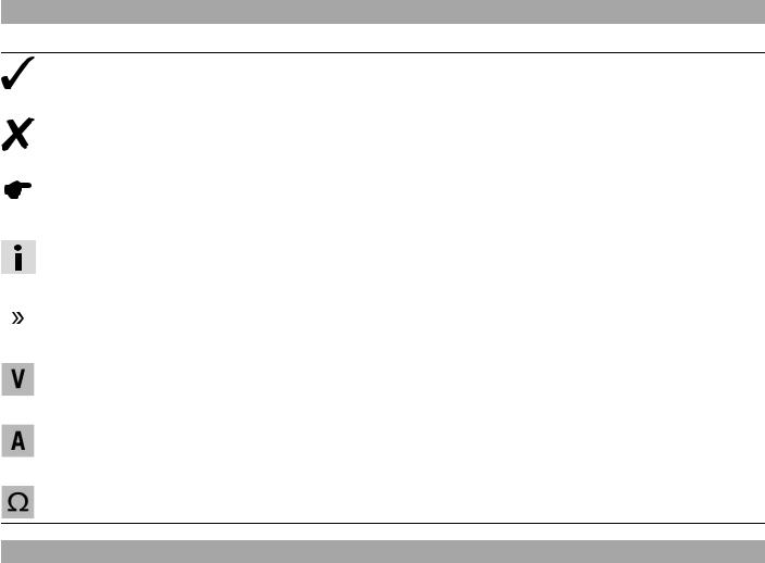
1.1Symbols used
The meaning of specific symbols is described below.
Indicates an expected reaction (e.g. of a work step or a function).
Indicates an unexpected reaction (e.g. of a work step or a function).
Indicates a page reference (more information is provided on the specified page).
Indicates information with more details or tips.
Indicates the result of a testing step.
Denotes a voltage measurement.
Denotes a current measurement.
Denotes a resistance measurement.
1.2Formats used
The typographical formats used in this document are explained below.
Proprietary name |
Identifies a proprietary name. |
Name® |
Identifies a protected name. |
Brand™ |
Identifies a trademark. |
|
|

2 |
SAFETY ADVICE |
7 |
2.1Repair Manual
Read this Repair Manual carefully and thoroughly before beginning work. It contains useful information and tips that will help you repair and maintain your vehicle.
This manual assumes that the necessary special KTM tools and KTM workplace and workshop equipment are available.
2.2Safety advice
A number of safety instructions need to be followed to operate the vehicle safely. Therefore, read this manual carefully. The safety instructions are highlighted in the text and are referred to at the relevant passages.
Info
The vehicle has various information and warning labels at prominent locations. Do not remove information/warning labels. If they are missing, you or others may not recognize dangers and may therefore be injured.
2.3Degrees of risk and symbols
Danger
Identifies a danger that will immediately and invariably lead to fatal or serious permanent injury if the appropriate measures are not taken.
Warning
Identifies a danger that is likely to lead to fatal or serious injury if the appropriate measures are not taken.
Caution
Identifies a danger that may lead to minor injuries if the appropriate measures are not taken.
Note
Identifies a danger that will lead to considerable machine and material damage if the appropriate measures are not taken.
Warning
Identifies a danger that will lead to environmental damage if the appropriate measures are not taken.
2.4Work rules
Special tools are necessary for certain tasks. The tools are not contained in the vehicle but can be ordered under the number in parentheses. E.g.: bearing puller (15112017000)
During assembly, non-reusable parts (e.g. self-locking screws and nuts, seals and seal rings, O-rings, pins, lock washers) must be replaced by new parts.
In some instances, a thread locker (e.g. Loctite®) is required. The manufacturer instructions for use must be followed.
After disassembly, clean the parts that are to be reused and check them for damage and wear. Change damaged or worn parts. After you complete the repair or service work, check the operating safety of the vehicle.

3 |
IMPORTANT INFORMATION |
8 |
3.1Guarantee, warranty
The work prescribed in the service schedule must be carried out by an authorized KTM workshop only and confirmed in the customer's Service & Warranty Booklet and in the KTM dealer.net; otherwise, all warranty claims will be void. No warranty claims can be considered for damage resulting from manipulations and/or alterations to the vehicle.
Additional information on the guarantee or warranty and the procedures involved can be found in the Service & Warranty Booklet.
3.2Operating and auxiliary substances
Warning
Environmental hazard Improper handling of fuel is a danger to the environment.
–Do not allow fuel to get into the ground water, the ground, or the sewage system.
Use the operating and auxiliary substances (such as fuel and lubricants) as specified in the manual.
3.3Spare parts, accessories
Only use spare parts and accessories approved and/or recommended by KTM. KTM accepts no liability for other products and any resulting damage or loss.
The current KTM PowerParts for your vehicle can be found on the KTM website.
International KTM Website: http://www.ktm.com
3.4Figures
The figures contained in the manual may depict special equipment.
In the interest of clarity, some components may be shown disassembled or may not be shown at all. It is not always necessary to disassemble the component to perform the activity in question. Please follow the instructions in the text.
4 |
SERIAL NUMBERS |
9 |
4.1Chassis number/type label
The chassis number 1 is stamped on the right of the steering head.
The type label 2 is on the right of the frame behind the steering head.
B00699-10
4.2Key number
The key number 1 can be found on the KEYCODECARD.
Info
You need the key number to order a spare key. Keep the KEYCODECARD in a safe place.
B00755-10
4.3Engine number
The engine number 1 is stamped on the left side of the engine under the engine sprocket.
B00700-10

5 |
MOTORCYCLE |
10 |
5.1Raising the motorcycle with the rear wheel stand
Note
Danger of damage The parked vehicle may roll away or fall over.
–Always place the vehicle on a firm and even surface.
–Mount the support of the wheel stand.
–Insert the adapter in the rear wheel stand.
Adapter (61029055130) ( p. 273)
Rear wheel stand (61029055400) ( p. 273)
–Stand the motorcycle upright, align the lifting gear with the swingarm and the adapters, and lift the motorcycle.
B01387-01
5.2Taking the motorcycle off of the rear wheel stand
Note
Danger of damage The parked vehicle may roll away or fall over.
–Always place the vehicle on a firm and even surface.
–Secure the motorcycle against falling over.
–Remove the rear wheel stand and lean the vehicle on the side stand 1.
–Remove the support of the wheel stand.
B00714-10
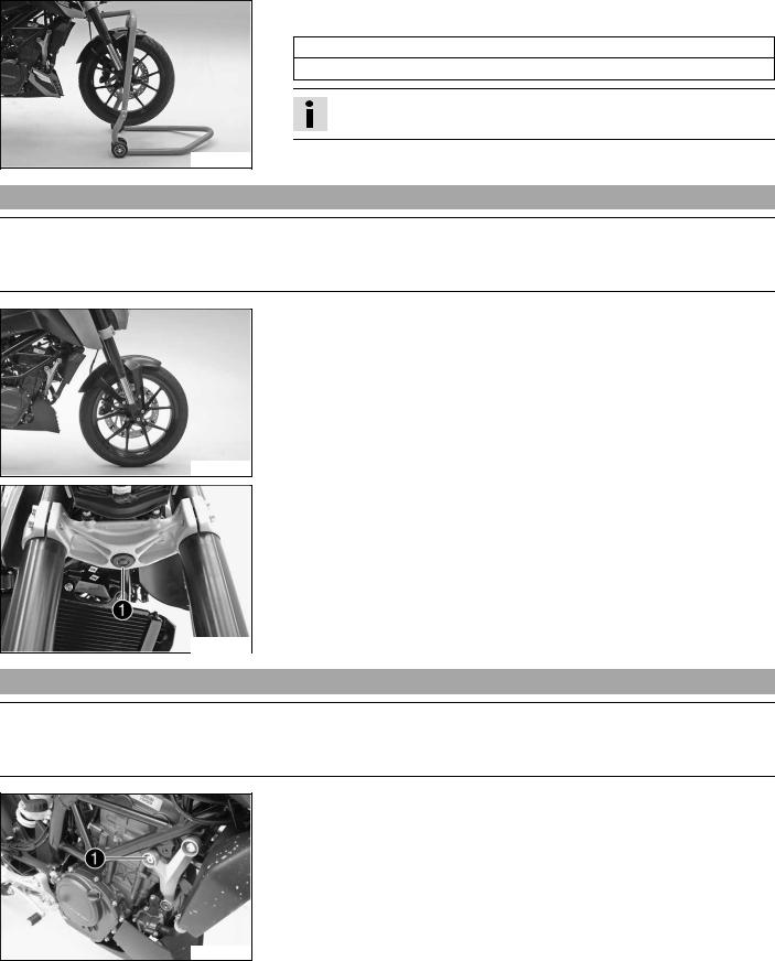
5.3Raising the motorcycle with the front wheel stand
Note
Danger of damage The parked vehicle may roll away or fall over.
–Always place the vehicle on a firm and even surface.
Preparatory work
–Raise the motorcycle with the rear wheel stand. ( p. 10)
Condition
–Remove cap 1.
C00196-10
5 MOTORCYCLE
C00197-01
11
–Move the handlebar to the straight-ahead position. Attach the lifting gear to the steering stem.
Adapter (61029955620) ( p. 274)
Front wheel stand (61029055500) ( p. 273)
Info
Always raise the rear of the motorcycle first.
–Raise the front of the motorcycle.
5.4Taking the motorcycle off of the front wheel stand
Note
Danger of damage The parked vehicle may roll away or fall over.
–Always place the vehicle on a firm and even surface.
–Secure the motorcycle against falling over.
–Remove the front wheel stand.
B01388-01
– Mount cap 1.
C00196-10
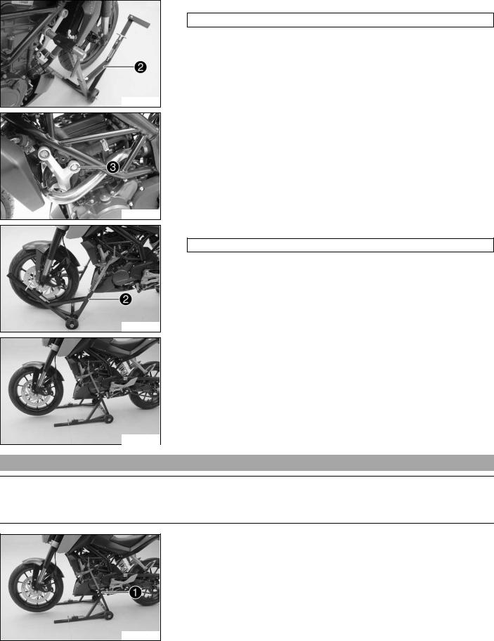
5.5Raising the motorcycle with the work stand
Note
Danger of damage The parked vehicle may roll away or fall over.
–Always place the vehicle on a firm and even surface.
–Remove screw 1.
307317-10
5 |
MOTORCYCLE |
12 |
–Mount special tool 2 on the right side of the vehicle. Work stand (62529055000) ( p. 274)
307318-10
–Remove screw 3.
307319-10
–Mount special tool 2 on the left side of the vehicle. Work stand (62529055000) ( p. 274)
307320-10
–Position the motorcycle upright, align the special tool and raise the motorcycle.
307321-10
5.6Removing the motorcycle from the work stand
Note
Danger of damage The parked vehicle may roll away or fall over.
–Always place the vehicle on a firm and even surface.
–Secure the motorcycle against falling over.
–Remove special tool 1.
307321-11

5 MOTORCYCLE
13
– Mount and tighten screws 23. Guideline
Screw, engine bearer on frame |
M8 |
30 Nm |
|
|
(22.1 lbf ft) |
|
|
|
307322-10
5.7Starting
Danger
Danger of poisoning Exhaust gases are toxic and inhaling them may result in unconsciousness and/or death.
–When running the engine, always make sure there is sufficient ventilation, and do not start or run the engine in an enclosed space without an effective exhaust extraction system.
Caution
Danger of accidents If the vehicle is operated with a discharged battery or without a battery, electronic components and safety equipment may be damaged.
–Never operate the vehicle with a discharged battery or without a battery.
Note
Engine failure Unfiltered intake air has a negative effect on the service life of the engine.
–Never ride the vehicle without an air filter since dust and dirt can get into the engine and result in increased wear.
Note
Engine failure High engine speeds in cold engines have a negative effect on the service life of the engine.
–Always warm up the engine at low engine speeds.
–Sit on the vehicle, take the weight off of the side stand, and move up all the way.
–Turn the emergency OFF switch to the position  .
.
–Switch on the ignition by turning the ignition key to the position  .
.
 After you switch on the ignition, you can hear the fuel pump working for about two seconds. The function check of the combination instrument is run at the same time.
–Shift gear to neutral.
|
The green idling speed indicator lamp N lights up. |
|
(Duke EU/MAL) |
B00782-10 |
The ABS warning lamp lights up and goes back out after starting off.
–Press the electric starter button  .
.
Info
Do not press the electric starter button until the combination instrument function check is finished.
When starting, DO NOT open the throttle. If you open the throttle during the starting procedure, fuel is not injected by the engine management system and the engine cannot start.
Press the starter for a maximum of 5 seconds. Wait for a least 5 seconds before trying again.
This motorcycle is equipped with a safety starting system. You can only start the engine if the transmission is in neutral or if the clutch is pulled when a gear is engaged. If the side stand is folded out and you shift into gear and release the clutch, the engine stops.

5 |
MOTORCYCLE |
14 |
Switching off ABS (Duke EU/MAL)
KTM recommends riding with ABS at all times. However, situations may arise in which ABS is not advantageous.
Condition
Vehicle stationary, engine running.
–Press the 1 button for 3 – 5 seconds.
 The ABS warning lamp starts flashing; ABS is deactivated.
401685-15
5.8Starting the motorcycle to make checks
Danger
Danger of poisoning Exhaust gases are toxic and inhaling them may result in unconsciousness and/or death.
–When running the engine, always make sure there is sufficient ventilation, and do not start or run the engine in an enclosed space without an effective exhaust extraction system.
Info
Press the starter for a maximum of 5 seconds. Wait for a least 5 seconds before trying again.
–Turn the emergency OFF switch to the position  .
.
–Shift gear to neutral.
–Switch on the ignition by turning the ignition key to the position  .
.
–Press the electric starter button  .
.
Info
Do not open the throttle.
B00782-10

6 |
FORK, TRIPLE CLAMP |
15 |
6.1Cleaning the dust boots of the fork legs
(Duke COL)
–Push dust boot 1 of both fork legs downwards.
Info
The dust boots should remove dust and coarse dirt particles from the fork tubes. Over time, dirt can penetrate behind the dust boots. If this dirt is not removed, the oil seals behind can start to leak.
|
|
|
|
|
Warning |
|
|
|
|
|
|
|
|
|
|
|
Danger of accidents Reduced braking efficiency due to oil or grease on |
|
304854-10 |
||||
|
|
|
|
|
the brake discs. |
–Always keep the brake discs free of oil and grease, and clean them with brake cleaner when necessary.
–Clean and oil the dust boots and inside fork tube of both fork legs.
Universal oil spray ( p. 271)
–Press the dust boots back into their normal position.
–Remove excess oil.
(Duke EU/MAL)
–Push dust boot 1 of both fork legs downwards.
Info
The dust boots should remove dust and coarse dirt particles from the fork tubes. Over time, dirt can penetrate behind the dust boots. If this dirt is not removed, the oil seals behind can start to leak.
|
|
|
|
|
Warning |
|
|
|
|
|
|
|
|
|
|
|
Danger of accidents Reduced braking efficiency due to oil or grease on |
|
307309-10 |
||||
|
|
|
|
|
the brake discs. |
–Always keep the brake discs free of oil and grease, and clean them with brake cleaner when necessary.
–Clean and oil the dust boots and inside fork tube of both fork legs.
Universal oil spray ( p. 271)
–Press the dust boots back into their normal position.
–Remove excess oil.
6.2Removing fork legs
304857-10
Preparatory work
–Raise the motorcycle with the work stand. ( p. 11)
–Tie the rear of the vehicle down.
–Dismount the front fender. ( p. 55)
Main work (Duke COL)
–Remove screws 1.
–Press back the brake linings with a light lateral tilting of the brake caliper on the brake disc. Pull the brake caliper carefully back from the brake disc and hang it to one side.
Info
Do not pull the hand brake lever when the brake caliper has been removed.
6 |
FORK, TRIPLE CLAMP |
16 |
–Loosen screws 2 and screw 3.
–Unscrew screw 2 about six turns and press your hand on the screw to push the wheel spindle out of the axle clamp. Remove screw 2.
Warning
Danger of accidents Reduced braking effect caused by damaged brake discs.
–Always lay the wheel down in such a way that the brake discs are not damaged.
304858-10
– Holding the front wheel, withdraw the wheel spindle. Take the front wheel out of the fork.
– Remove screws 4.
– Remove the cable binder and hang the wheel speed sensor to one side.
304859-10
–Loosen screws 5. Remove the fork legs from the bottom.
304860-10
307310-10
307311-10
307312-10
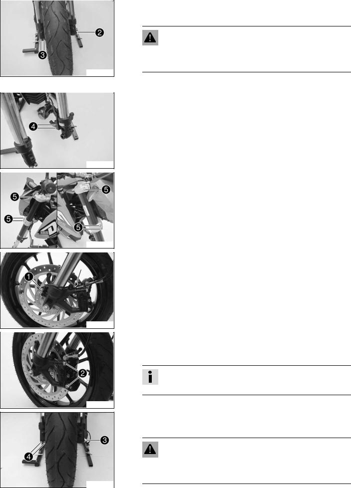
(Duke EU/MAL)
–Remove screw 1.
–Remove the cable binder.
–Pull off the ABS sensor and hang it to one side.
–Remove screws 2.
–Press back the brake linings with a light lateral tilting of the brake caliper on the brake disc. Pull the brake caliper carefully back from the brake disc and hang it to one side.
Info
Do not pull the hand brake lever when the brake caliper has been removed.
–Loosen screws 3 and screw 4.
–Unscrew screw 3 about six turns and press your hand on the screw to push the wheel spindle out of the axle clamp. Remove screw 3.
Warning
Danger of accidents Reduced braking effect caused by damaged brake discs.
–Always lay the wheel down in such a way that the brake discs are not damaged.

6 |
FORK, TRIPLE CLAMP |
17 |
–Holding the front wheel, withdraw the wheel spindle. Take the front wheel out of the fork.
–Loosen screws 5. Remove the fork legs from the bottom.
307313-10
6.3Installing the fork legs
Warning
Danger of accidents Modifications to the suspension settings can seriously alter the vehicle's ride behavior.
–Following modifications, ride slowly at first to get the feel of the new ride behavior.
Main work (Duke COL)
–Push the fork legs into the triple clamps.
–Align the fork legs in the required position using the fork rings.
|
304863-10 |
|
|
|
|
|
|
|
|
– |
Tighten screws 1. |
|
|
|
|
|
|
|
||
|
|
|
|
Guideline |
|
|
|
|
|
|
|
|
|
|
|
|
|
Screw, top triple clamp |
M8 |
11 Nm |
|
|
|
|
|
|
(8.1 lbf ft) |
|
|
|
– |
|
|
|
|
|
|
Tighten screws 2. |
|
|
|
|
|
|
|
Guideline |
|
|
|
|
|
|
|
|
|
|
|
|
|
Screw, bottom triple clamp |
M8 |
15 Nm |
|
|
|
|
|
|
(11.1 lbf ft) |
|
304860-11 |
|
|
|
|
|
|
|
|
|
|
|
–Position the wheel speed sensor. Mount and tighten screws 3. Guideline
Remaining screws, chassis |
M4 |
4 Nm (3 lbf ft) |
|
|
|
304859-11
–Check the wheel bearing for damage and wear. » If the wheel bearing is damaged or worn:
– Change the wheel bearing.
–Clean and grease the shaft seal rings 4 and contact surfaces A of the spacers.
Long-life grease ( p. 270)
304861-10

6 |
FORK, TRIPLE CLAMP |
18 |
–Clean screw 5 and the wheel spindle.
–Lift the front wheel into the fork, position it, and insert the wheel spindle.
–Mount and tighten screw 5. Guideline
Screw, front wheel spindle |
M8 |
30 Nm |
|
|
(22.1 lbf ft) |
|
|
|
304858-11
304857-11
304862-10
– Position the brake calipers and check that the brake linings are seated correctly.
– Mount screws 6 but do not tighten yet.
– Operate the hand brake lever repeatedly until the brake linings are in contact with the brake disc and there is a pressure point. Fix the hand brake lever in the activated position.
The brake calipers straighten.
– Tighten screws 6. Guideline
Screw, front brake |
M8x1 |
27 Nm |
Loctite® 243™ |
caliper |
|
(19.9 lbf ft) |
|
|
|
|
|
– Remove the fixation of the hand brake lever.
– Unload the rear of the vehicle.
– Remove the motorcycle from the work stand. ( p. 12)
– Pull the front brake and compress the fork powerfully a few times.
The fork legs straighten.
– Tighten screws 7. Guideline
Screw, fork stub |
M8 |
15 Nm |
|
|
(11.1 lbf ft) |
|
|
|
(Duke EU/MAL)
–Push the fork legs into the triple clamps.
–Align the fork legs in the required position using the fork rings.
|
307314-10 |
|
|
|
|
|
|
|
|
– |
Tighten screws 1. |
|
|
|
|
|
|
|
||
|
|
|
|
Guideline |
|
|
|
|
|
|
|
|
|
|
|
|
|
Screw, top triple clamp |
M8 |
11 Nm |
|
|
|
|
|
|
(8.1 lbf ft) |
|
|
|
– |
|
|
|
|
|
|
Tighten screws 2. |
|
|
|
|
|
|
|
Guideline |
|
|
|
|
|
|
|
|
|
|
|
|
|
Screw, bottom triple clamp |
M8 |
15 Nm |
|
|
|
|
|
|
(11.1 lbf ft) |
|
307313-11 |
|
|
|
|
|
|
|
|
|
|
|
|
|
|
|
|
|
|
|
6 |
FORK, TRIPLE CLAMP |
19 |
–Check the wheel bearing for damage and wear. » If the wheel bearing is damaged or worn:
– Change the wheel bearing.
–Clean and grease the shaft seal rings 3 and contact surfaces A of the spacers.
Long-life grease ( p. 270)
307315-10
307312-11
307311-11
307310-11
– Clean screw 4 and the wheel spindle.
– Lift the front wheel into the fork, position it, and insert the wheel spindle.
– Mount and tighten screw 4. Guideline
Screw, front wheel spindle |
M8 |
30 Nm |
|
|
(22.1 lbf ft) |
|
|
|
– Position the brake calipers and check that the brake linings are seated correctly.
– Mount screws 5 but do not tighten yet.
– Operate the hand brake lever repeatedly until the brake linings are in contact with the brake disc and there is a pressure point. Fix the hand brake lever in the activated position.
|
The brake calipers straighten. |
|
|
|
|
||
– |
Tighten screws 5. |
|
|
|
|
|
|
|
Guideline |
|
|
|
|
|
|
|
|
|
|
|
|
|
|
|
Screw, front brake |
|
M8x1 |
|
|
27 Nm |
Loctite® 243™ |
|
caliper |
|
|
|
|
(19.9 lbf ft) |
|
|
|
|
|
|
|
|
|
– Remove the fixation of the hand brake lever. |
|
|
|||||
– Unload the rear of the vehicle. |
|
|
|
|
|||
– |
Remove the motorcycle from the work stand. ( p. 12) |
|
|||||
– Position the ABS sensor. |
|
|
|
|
|
||
– Mount and tighten screw 6. |
|
|
|
|
|
||
|
Guideline |
|
|
|
|
|
|
|
|
|
|
|
|||
|
Screw, wheel speed sensor holder |
M6 |
|
8 Nm (5.9 lbf ft) |
|||
|
|
|
|
|
|
|
|
–Route the cable and secure with a cable binder.
–Pull the front brake and compress the fork powerfully a few times.  The fork legs straighten.
–Tighten screws 7. Guideline
Screw, fork stub |
M8 |
15 Nm |
|
|
(11.1 lbf ft) |
|
|
|
307316-10
Finishing work
–Install front fender. ( p. 55)
6 |
FORK, TRIPLE CLAMP |
20 |
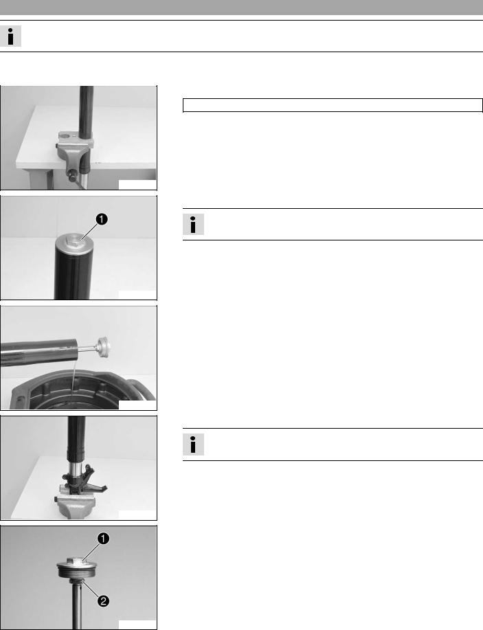
6.4Disassembling the fork legs
Info
These operations are the same on both fork legs.
Condition
The fork legs have been removed.
–Clamp the fork leg in the area of the lower triple clamp. Clamping stand (T612S) ( p. 280)
201505-10
–Loosen the screw cap 1.
Info
The screw cap cannot be removed yet.
201506-10
–Empty the fork oil.
201507-10
–Release the fork leg and clamp it with the fork stub.
Info
Use soft jaws.
201508-10
–Push the outer tube downward.
–Hold screw cap 1. Loosen nut 2. Remove the screw cap.
201509-10

6 |
FORK, TRIPLE CLAMP |
21 |
–Detach the outer tube from the inner tube.
Info
Place a container underneath to catch any oil that may run out.
201510-10
–Unclamp the inner tube. Drain the oil.
201511-10
–Clamp the outer tube in the area of the lower triple clamp. Clamping stand (T612S) ( p. 280)
–Remove dust boot 3.
201512-10
–Remove lock ring 4.
Info
The lock ring has a beveled end where a screwdriver can be applied.
201513-10
–Remove seal ring 5. Remove support ring 6.
201514-10
–Unclamp the outer tube.
–Heat up the outer tube in the area of sliding bushing 7. Guideline
50 °C (122 °F)
–Strike the lower edge of the outer fork tube on a wooden board.  Sliding bushing 7 must fall out of its seat.
201515-10

6 |
FORK, TRIPLE CLAMP |
22 |
6.5Checking the fork legs
Condition
The fork legs have been disassembled.
–Check the inner tube and the axle clamp for damage. » If damage is found:
– Change the fork leg.
201516-10
–Measure the outside diameter of the inner tube in several places.
External diameter of inner tube |
42.975… 43.005 mm (1.69193… |
|
1.69311 in) |
|
|
»If the measured value is less than the specified value:
– Change the fork leg.
200684-10
200685-10
200632-10
–Measure the run-out of the inner tube.
Run-out of inner tube |
≤ 0.20 mm (≤ 0.0079 in) |
|
|
»If the measured value is greater than the specified value:
–Change the fork leg.
–Check the outer tube for damage.
»If damage is found:
–Change the fork leg.
–Check the surface of the sliding bushings.
»If the dark layer A is worn off:
–Change the fork leg.
201517-10

6 |
FORK, TRIPLE CLAMP |
23 |
6.6Assembling the fork legs
Info
These operations are the same on both fork legs.
Preparatory work
–Check the fork legs. ( p. 22)
Main work
–Clamp in the inner tube with the axle clamp. Guideline
Use soft jaws.
–Grease and slide on dust boot 1.
Lubricant (T511) ( p. 270)
202092-10 |
Info |
|
Always change the dust boot, lock ring, seal ring, and support ring. |
||
|
Install the dust boot with the sealing lip and spring expander facing downward.
–Slide on lock ring 2.
–Grease and slide on seal ring 3.
Lubricant (T511) ( p. 270)
Info
Mount with the sealing lip facing down and the open side facing up.
–Slide on support ring 4.
–Sand the edges of sliding bushing 5 with 600-grit sandpaper, then clean and grease.
Fork oil (SAE 4) (48601166S1) ( p. 269)
–Slide on sliding bushing 5.
–Warm up the outer tube in the lower sliding bushing area A. Guideline
50 °C (122 °F)
–Slide the outer tube onto the inner tube.
–Hold the sliding bushing with the longer shoulder of the special tool.
Mounting tool (T528S) ( p. 280)
–Push the sliding bushing all the way into the outer tube.
202093-10
–Position the support ring.
–Hold the seal ring with the shorter shoulder of the special tool.
Mounting tool (T528S) ( p. 280)
–Push the seal ring and support ring all the way into the outer tube.
202094-10

6 |
FORK, TRIPLE CLAMP |
24 |
–Mount lock ring 2.
Info
The lock ring must engage audibly.
202095-10
202096-10
202097-10
201523-10
–Install dust boot 1.
–Mount screw cap 6 onto the piston rod.
Info
Nut 7 must be turned all the way down.
– Hold the screw cap and tighten the nut. Guideline
|
Nut, piston rod on screw cap |
M12x1 |
30 Nm |
|
|
|
|
|
(22.1 lbf ft) |
|
|
|
|
|
– Fill it with fork oil. |
|
|
|
|
|
|
|
|
|
|
Fork oil |
450 ml |
Fork oil (SAE 4) (48601166S1) |
|
|
|
(15.21 fl. oz.) |
( p. 269) |
|
|
|
|
|
|
|
|
|
|
|
Info
If it should be impossible to add the full quantity of oil, close the screw cap of the outer tube, unclamp the fork and bounce a number of times. Then add the remaining quantity.
–Push the outer tube upward.
–Mount screw cap 6.
–Unclamp the fork leg in the area of the lower triple clamp.
|
|
Clamping stand (T612S) ( |
p. 280) |
|
|
|
|
|
|
|
|
|
– Tighten the screw cap. |
|
|
|
|
|
|
Guideline |
|
|
|
|
|
|
|
|
|
|
|
Screw cap on outer tube |
|
M47x1.5 |
30 Nm |
|
|
|
|
|
(22.1 lbf ft) |
201522-10 |
|
|
|
|
|
|
|
|
|
|
|
6.7Removing the lower triple clamp
Preparatory work
–Raise the motorcycle with the work stand. ( p. 11)
–Tie the rear of the vehicle down.
–Dismount the front fender. ( p. 55)
–Remove the fork legs. ( p. 15)
6 |
FORK, TRIPLE CLAMP |
25 |
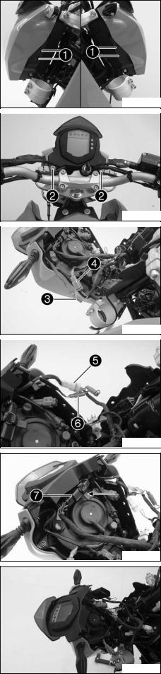
Main work
–Remove expanding rivets 1.
307323-10
–Remove screws 2.
–Lift the headlight mask slightly and swing forward.
307324-10
–Detach connectors 3 and 4.
307325-10
–Detach connectors 5 and 6.
307326-10
–Remove the connector holder.
–Disconnect connector 7.
307327-10
–Remove the combination instrument.
307328-10

6 |
FORK, TRIPLE CLAMP |
26 |
307329-10
307330-10
307331-10
307332-10
307333-10
–Remove screws 8.
–Remove the headlight mask.
–Remove screw 9.
–Remove the upper triple clamp with the handlebar and set aside.
Info
Protect the vehicle and its attachments from damage by covering them.
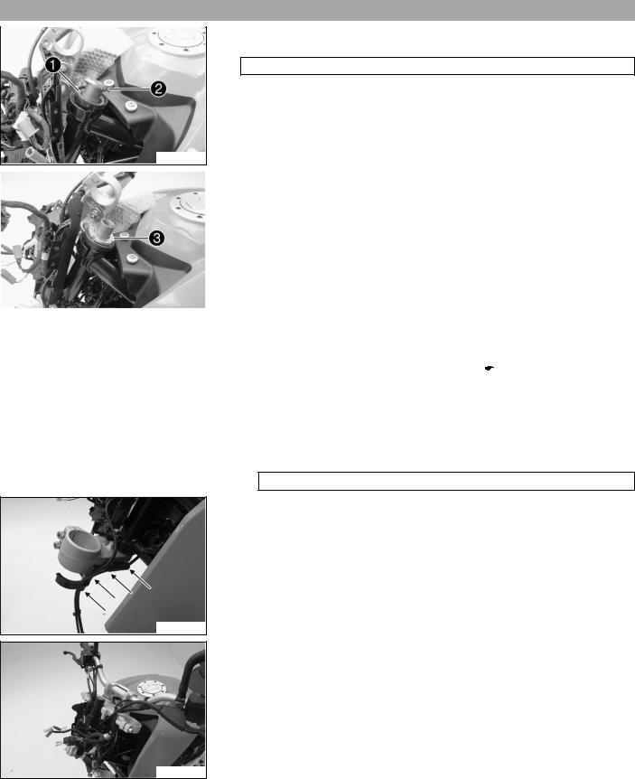
–Expose the cable.
–Remove nut bk.
Castle nut wrench; ½" drive (90129050100) ( p. 278)
–Remove washer bl.
–Remove steering head bearing bm.
–Remove the lower triple clamp with the steering stem.
307334-10
6 |
FORK, TRIPLE CLAMP |
27 |
6.8Installing the lower triple clamp
Main work
–Clean the bearing and sealing elements, check for damage, and grease. High viscosity grease ( p. 270)
–Insert the lower triple clamp with the steering stem.
–Mount the upper steering head bearing 1.
–Mount washer 2 with the cut-out facing downward.
307334-11
|
|
Alternative 1 |
|
|
|
|
|
|
|
|
|
||
|
|
A new steering head bearing is used. |
|
|
|
|
|
|
– Mount and tighten nut 3. |
|
|
|
|
|
|
|
Guideline |
|
|
|
|
|
|
|
|
|
|
|
|
|
Nut, steering head |
M30x1 |
|
Step 1 |
|
|
|
|
|
|
50 Nm |
|
|
|
|
|
|
(36.9 lbf ft) |
|
|
|
|
|
|
2nd stage |
|
|
|
|
|
|
(loosen, counter- |
|
307333-11 |
|
|
|
|
clockwise) |
|
|
|
|
|
||
|
|
|
|
|
|
2 turns |
|
|
|
|
|
|
Step 3 |
|
|
|
|
|
|
5 Nm (3.7 lbf ft) |
|
|
|
|
|
|
|
|
|
|
|
|
||
|
|
|
Castle nut wrench; ½" drive (90129050100) ( |
p. 278) |
||
|
|
|
|
|
|
|
Alternative 2
The steering head bearing is used again.
–Mount and tighten nut 3. Guideline
Nut, steering head |
M30x1 |
5 Nm (3.7 lbf ft) |
|
|
|
Castle nut wrench; ½" drive (90129050000) ( p. 278)
–Secure the cable in the bracket.
307332-10
–Position the upper triple clamp with the handlebar.
307331-10

6 |
FORK, TRIPLE CLAMP |
|
28 |
||
|
|
– Mount screw 4 with the washer but do not tighten it yet. |
|
||
|
|
|
|||
|
|
|
Guideline |
|
|
|
|
|
|
|
|
|
|
|
Screw, top steering head |
M16x1.5 |
52 Nm |
|
|
|
|
|
(38.4 lbf ft) |
|
|
|
|
|
|
Holding lugs A reach into the drilled holes.
307330-11
–Position the headlight mask.
–Mount and tighten screw 5. Guideline
Screw, headlight mask |
M6 |
11 Nm (8.1 lbf ft) |
|
|
|
307329-11
–Position the combination instrument.
–Plug in connector 6.
–Mount the connector holder 7.
307327-11
–Plug in connectors 8 and 9.
307326-11
–Plug in connectors bk and bl.
307325-11
–Fold the headlight mask up.
–Mount and tighten screws bm. Guideline
Screw, headlight mask |
M6 |
11 Nm (8.1 lbf ft) |
|
|
|
307324-11
Loading...