


OWNER'S MANUAL 2012
65 SX
Art. no. 3211712en

DEAR KTM CUSTOMER |
1 |
Congratulations on your decision to purchase a KTM motorcycle. You are now the owner of a state-of-the-art sports motorcycle that will give you and your child enormous pleasure if you service and maintain it accordingly.
We wish you a lot of enjoyment in riding this vehicle.
Enter the serial numbers of your vehicle below.
Chassis number ( p. 9) |
Dealer's stamp |
Engine number ( p. 9)
p. 9)
The owner's manual corresponded to the latest state of this series at the time of printing. Slight deviations resulting from continuing development and design can, however, not be completely excluded.
All specifications are non-binding. KTM Sportmotorcycle AG specifically reserves the right to modify or delete technical specifications, prices, colors, forms, materials, services, designs, equipment, etc., without prior notice and without specifying reasons, to adapt these to local conditions, as well as to stop production of a particular model without prior notice. KTM accepts no liability for delivery options, deviations from illustrations and descriptions, as well as misprints and other errors. The models portrayed partly contain special equipment that does not belong to the regular scope of delivery.
© 2011 KTM-Sportmotorcycle AG, Mattighofen Austria All rights reserved
Reproduction, even in part, as well as copying of all kinds, is permitted only with the express written permission of the copyright owner.
ISO 9001(12 100 6061)
According to the international quality management standard ISO 9001, KTM uses quality assurance processes that lead to the maximum possible quality of the products.
Issued by: TÜV Management Service
KTM-Sportmotorcycle AG
5230 Mattighofen, Austria
TABLE OF CONTENTS |
2 |
MEANS OF REPRESENTATION ............................................ |
4 |
IMPORTANT INFORMATION ................................................ |
5 |
VIEW OF VEHICLE............................................................... |
7 |
View of the vehicle from the left front (example)................. |
7 |
View of the vehicle from the right rear (example) ................ |
8 |
SERIAL NUMBERS.............................................................. |
9 |
Chassis number............................................................... |
9 |
Engine number................................................................ |
9 |
Shock absorber part number............................................. |
9 |
CONTROLS ....................................................................... |
10 |
Clutch lever .................................................................. |
10 |
Hand brake lever ........................................................... |
10 |
Throttle grip.................................................................. |
10 |
Kill switch .................................................................... |
10 |
Opening the filler cap .................................................... |
10 |
Closing the filler cap...................................................... |
11 |
Fuel tap........................................................................ |
11 |
Choke........................................................................... |
11 |
Shift lever..................................................................... |
12 |
Kickstarter.................................................................... |
12 |
Foot brake lever............................................................. |
12 |
Plug-in stand ................................................................ |
12 |
PUTTING INTO OPERATION............................................... |
13 |
Advice on first use......................................................... |
13 |
Running in the engine.................................................... |
14 |
RIDING INSTRUCTIONS .................................................... |
15 |
Checks and maintenance measures when preparing for |
|
use .............................................................................. |
15 |
Starting ........................................................................ |
15 |
Starting off ................................................................... |
16 |
Shifting, riding.............................................................. |
16 |
Braking ........................................................................ |
16 |
Stopping, parking .......................................................... |
17 |
Refueling...................................................................... |
17 |
SERVICE SCHEDULE......................................................... |
19 |
Service schedule ........................................................... |
19 |
TUNING THE CHASSIS...................................................... |
21 |
Adjusting the compression damping of the fork ................ |
21 |
Adjusting the rebound damping of the fork....................... |
21 |
Adjusting the compression damping of the shock |
|
absorber ....................................................................... |
21 |
Adjusting the rebound damping of the shock absorber....... |
22 |
Measuring rear wheel sag unloaded ................................. |
22 |
Checking the static sag of the shock absorber .................. |
22 |
Checking the riding sag of the shock absorber .................. |
23 |
Adjusting the spring preload of the shock absorber x...... |
23 |
Adjusting the riding sag x............................................. |
24 |
Handlebar position ........................................................ |
24 |
Adjusting handlebar position x...................................... |
24 |
MAINTENANCE WORK ON THE CHASSIS ........................... |
26 |
Raising the motorcycle with a lift stand ........................... |
26 |
Removing the motorcycle from the lift stand .................... |
26 |
Bleeding fork legs.......................................................... |
26 |
Cleaning the dust boots of the fork legs ........................... |
26 |
Removing the fork protector x....................................... |
27 |
Installing the fork protector x....................................... |
27 |
Removing the fork legs x.............................................. |
28 |
Installing the fork legs x............................................... |
28 |
Removing the lower triple clamp x................................ |
29 |
Installing the lower triple clamp x................................. |
29 |
Checking play of steering head bearing............................ |
31 |
Adjusting the play of the steering head bearing x............ |
31 |
Greasing the steering head bearing x............................. |
32 |
Dismounting the start number plate ................................ |
32 |
Installing the start number plate ..................................... |
32 |
Dismounting the front fender .......................................... |
32 |
Installing the front fender............................................... |
33 |
Removing the shock absorber x..................................... |
33 |
Installing shock absorber x........................................... |
33 |
Removing the seat ......................................................... |
33 |
Mounting the seat ......................................................... |
34 |
Removing the air filter x............................................... |
34 |
Installing the air filter x............................................... |
34 |
Cleaning the air filter and air filter box x........................ |
35 |
Removing main silencer ................................................. |
35 |
Installing the main silencer ............................................ |
36 |
Changing the glass fiber yarn filling of the main |
|
silencer x................................................................... |
36 |
Dismounting the fuel tank x......................................... |
36 |
Installing the fuel tank x.............................................. |
37 |
Removing the chain guard .............................................. |
38 |
Installing the chain guard............................................... |
38 |
Checking chain dirt ....................................................... |
39 |
Cleaning the chain......................................................... |
39 |
Checking the chain tension ............................................ |
39 |
Adjusting the chain tension ............................................ |
40 |
Checking the chain, rear sprocket, engine sprocket, and |
|
chain guide................................................................... |
40 |
Adjusting the chain guide x.......................................... |
42 |
Checking the frame x................................................... |
42 |
Checking the swingarm x............................................. |
42 |
Checking the throttle cable routing.................................. |
43 |
Checking the rubber grip ................................................ |
43 |
Additionally securing the rubber grip ............................... |
43 |
Adjusting basic position of clutch lever............................ |
43 |
Checking the fluid level of hydraulic clutch...................... |
44 |
Changing the hydraulic clutch fluid x............................ |
44 |
BRAKES ........................................................................... |
45 |
Checking free travel of hand brake lever........................... |
45 |
Adjusting the basic position of the hand brake lever.......... |
45 |
Checking brake discs ..................................................... |
45 |
Checking front brake fluid level....................................... |
46 |
Adding front brake fluid x............................................ |
46 |
Checking the front brake linings...................................... |
47 |
Removing front brake linings x..................................... |
47 |
Installing the front brake linings x................................. |
48 |
Changing the front brake linings x................................. |
48 |
Checking the free travel of the foot brake lever ................. |
49 |
Adjusting the free travel of the foot brake lever x............ |
49 |
Adjusting the basic position of the foot brake lever x...... |
50 |
Checking rear brake fluid level........................................ |
50 |
Adding rear brake fluid x.............................................. |
51 |
Checking the rear brake linings ....................................... |
52 |
Removing rear brake linings x....................................... |
52 |
Installing the rear brake linings x.................................. |
52 |
Changing the rear brake linings x.................................. |
53 |
WHEELS, TIRES ............................................................... |
55 |
Removing the front wheel x.......................................... |
55 |
Installing the front wheel x........................................... |
55 |
Removing the rear wheel x........................................... |
56 |
Installing the rear wheel x............................................ |
56 |
Checking the tire condition............................................. |
57 |

TABLE OF CONTENTS |
3 |
Checking tire air pressure............................................... |
57 |
Checking spoke tension.................................................. |
57 |
COOLING SYSTEM ............................................................ |
59 |
Cooling system .............................................................. |
59 |
Checking the antifreeze and coolant level ........................ |
59 |
Checking the coolant level.............................................. |
60 |
Draining the coolant x.................................................. |
60 |
Refilling the coolant x.................................................. |
61 |
TUNING THE ENGINE ....................................................... |
62 |
Checking the play in the throttle cable............................. |
62 |
Adjusting the play in the throttle cable x....................... |
62 |
Carburetor - idle ............................................................ |
62 |
Carburetor - adjusting the idle speed x.......................... |
62 |
Emptying the carburetor float chamber x....................... |
63 |
MAINTENANCE WORK ON THE ENGINE............................. |
64 |
Checking the gear oil level.............................................. |
64 |
Changing the gear oil x................................................ |
64 |
Draining the gear oil x................................................. |
64 |
Filling up with gear oil x.............................................. |
65 |
Adding gear oil x......................................................... |
65 |
CLEANING, CARE ............................................................. |
67 |
Cleaning motorcycle ...................................................... |
67 |
STORAGE ......................................................................... |
68 |
Storage......................................................................... |
68 |
Preparing for use after storage ........................................ |
68 |
TROUBLESHOOTING......................................................... |
69 |
TECHNICAL DATA - ENGINE.............................................. |
71 |
TECHNICAL DATA - ENGINE TIGHTENING TORQUES.......... |
72 |
TECHNICAL DATA - CARBURETOR..................................... |
73 |
Basic setting................................................................. |
73 |
Carburetor configuration................................................. |
73 |
TECHNICAL DATA - FORK.................................................. |
75 |
TECHNICAL DATA - SHOCK ABSORBER ............................. |
76 |
TECHNICAL DATA - CHASSIS ............................................ |
77 |
TECHNICAL DATA - CHASSIS TIGHTENING TORQUES ........ |
78 |
SUBSTANCES................................................................... |
79 |
AUXILIARY SUBSTANCES.................................................. |
81 |
STANDARDS..................................................................... |
83 |
INDEX .............................................................................. |
84 |
MEANS OF REPRESENTATION |
4 |
Symbols used
The symbols used are explained in the following.
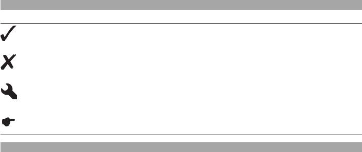
Indicates an expected reaction (e.g., to a work step or a function).
Indicates an unexpected reaction (e.g., to a work step or a function).
All work marked with this symbol requires specialist knowledge and technical understanding. In the interest of the safety of your child, have these jobs done in an authorized KTM workshop! There, your motorcycle will be serviced optimally by specially trained experts using the specialist tools required.
Identifies a page reference (more information is provided on the specified page).
Formats used
The typographical and other formats used are explained in the following.
Proper name |
Identifies a proper name. |
Name® |
Identifies a protected name. |
Brand™ |
Identifies a brand in merchandise traffic. |
|
|
IMPORTANT INFORMATION |
5 |
Use definition
KTM sport motorcycles are designed and built to withstand the normal stresses and strains of competitive use. The motorcycles comply with currently valid regulations and categories of the top international motorsport organizations.
Info
The motorcycle must be used only in closed off areas remote from public road traffic.
Service
A prerequisite for perfect operation and prevention of wear is that the engine and chassis service, care and adjustment work described in the owner's manual are properly carried out. Poor adjustment and tuning of the engine and chassis can lead to damage and breakage of components.
Using the motorcycle in difficult conditions such as on sand or very muddy or wet terrain can lead to above-average wear of components such as the transmission train or the brakes. For this reason, it may be necessary to service or replace worn parts before the limit specified in the service schedule is reached.
Pay careful attention to the prescribed running-in period, inspection and service intervals. If you observe these exactly, you will ensure a much longer service life for your motorcycle.
Warranty
The work prescribed in the service schedule must be carried out in an authorized KTM workshop only and confirmed in the customer's service record and in the KTM dealer.net since otherwise no warranty claims will be honored. No warranty claims can be honored for damage resulting from manipulations and/or alterations to the vehicle.
Fuel, oils, etc.
You should use the fuels, oils and greases according to specifications as listed in the owner's manual.
Spare parts, accessories
For your own safety, only use spare parts and accessory products that have been approved and/or recommended by KTM and have them installed by an authorized KTM workshop. KTM accepts no liability for other products and any resulting damage or loss. Certain spare parts and accessories are specified in parentheses in the descriptions. Your KTM dealer will be glad to advise you.
The current KTM PowerParts for your vehicle can be found on the KTM website.
International KTM Website: http://www.ktm.com
Work rules
Special tools are needed for certain tasks. They are not included with the vehicle but can be ordered under the number in parentheses. Ex.: bearing puller (15112017000)
During assembly, non-reusable parts (e.g. self-locking screws and nuts, seals, seal rings, O-rings, pins, lock washers) must be replaced by new parts.
If a thread locker is used for the screw connections (e.g. Loctite®), follow the specific manufacturer instructions regarding its use. Parts that are to be reused after disassembly must be cleaned and checked for damage and wear. Change damaged or worn parts. After repair and maintenance, ensure that the vehicle is roadworthy.
Transport
Note
Danger of damage The parked vehicle may roll away or fall over.
–Always place the vehicle on a firm and even surface.
Note
Fire hazard Some vehicle components become very hot when the vehicle is operated.
–Do not park the vehicle near flammable or explosive substances. Do not place objects on the vehicle while it is still warm from being run. Always let the vehicle cool first.
–Switch off the engine.
–Use straps or other suitable devices to secure the motorcycle against accidents or falling over.
IMPORTANT INFORMATION |
6 |
Environment
Motorcycling is a wonderful sport and we naturally hope that you and your child will be able to enjoy it to the fullest. However, it is a potential problem for the environment and can lead to conflicts with other persons. But if you use your motorcycle responsibly, you can ensure that such problems and conflicts do not have to occur. To protect the future of motorcycle sport, make sure that your child uses the motorcycle legally, display environmental consciousness, and respect the rights of others.
Notes/warnings
Pay close attention to the notes/warnings.
Info
Various information and warning labels are affixed to the vehicle. Do not remove information/warning labels. If they are missing, you or others may not recognize potential hazards and may therefore be injured.
Grades of risks
Danger
Identifies a danger that will immediately and invariably lead to fatal or serious permanent injury if the appropriate measures are not taken.
Warning
Identifies a danger that is likely to lead to fatal or serious injury if the appropriate measures are not taken.
Caution
Identifies a danger that may lead to minor injuries if the appropriate measures are not taken.
Note
Identifies a danger that will lead to considerable machine and material damage if the appropriate measures are not taken.
Warning
Identifies a danger that will lead to environmental damage if the appropriate measures are not taken.
Owner's manual
–Carefully read this owner's manual in its entirety together with your child before letting your child ride the motorcycle for the first time. It contains a lot of information and tips to help you and your child operate and handle the motorcycle. Only then will you find out how to customize the motorcycle ideally for your child's use and how to protect your child from injury. The owner's manual also contains important information on servicing the motorcycle.
–The owner's manual is an important component of the motorcycle and should be handed over to the new owner if the vehicle is sold.
VIEW OF VEHICLE |
7 |
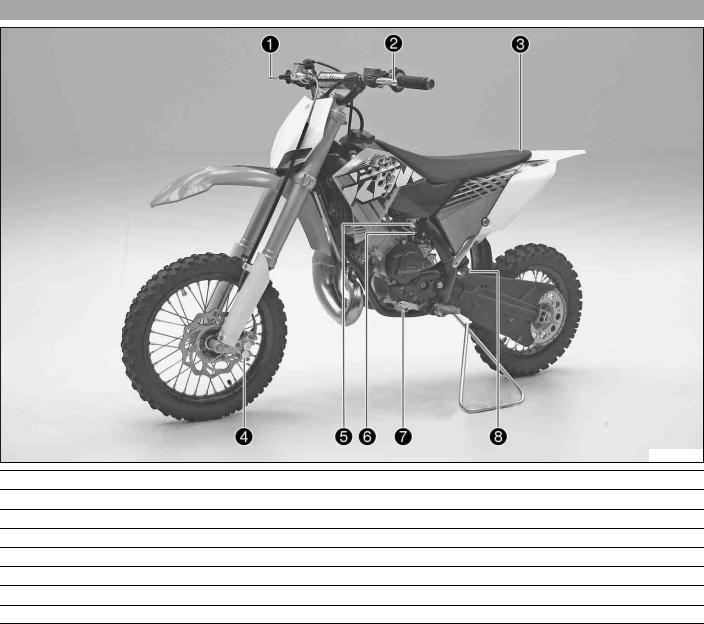
View3.1 of the vehicle from the left front (example)
C00016-10
1Hand brake lever ( p. 10)
2Clutch lever ( p. 10)
3Quick release for seat lock
4Front brake caliper
5Fuel tap ( p. 11)
6Choke ( p. 11)
7Shift lever ( p. 12)
8Shock absorber rebound adjustment
VIEW OF VEHICLE |
8 |
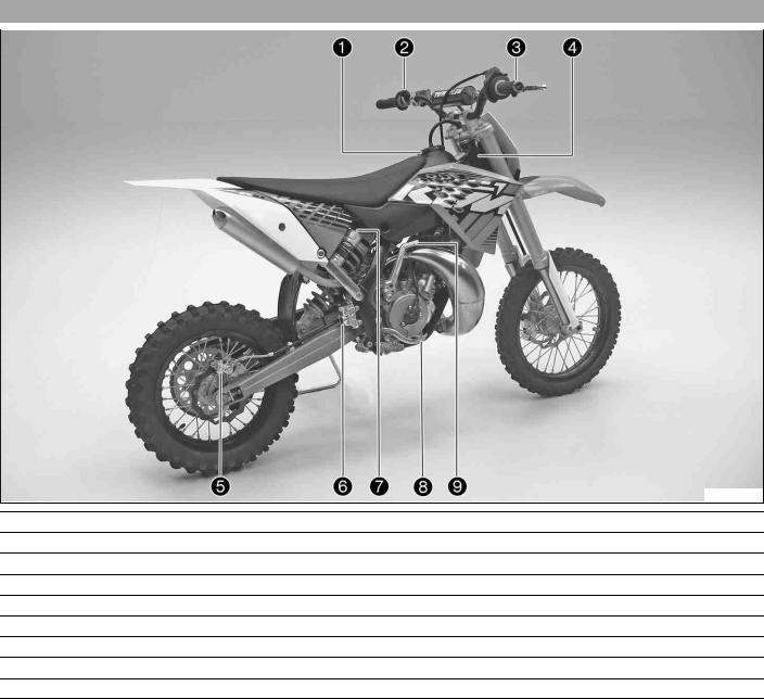
View3.2 of the vehicle from the right rear (example)
C00017-10
1Filler cap
2Kill switch ( p. 10)
3Throttle grip ( p. 10)
4Chassis number ( p. 9)
p. 9)
5Rear brake caliper
6Level viewer for brake fluid, rear
7Shock absorber compression adjustment
8Foot brake lever ( p. 12)
9Kickstarter ( p. 12)
SERIAL NUMBERS |
9 |
Chassis4.1 number
The chassis number is stamped on right of the steering head.
700390-01
Engine4.2 number
The engine number is stamped on the left side of the engine under the engine sprocket.
700391-01
Shock4.3 absorber part number
The shock absorber part number is stamped on the top of the shock absorber above the adjusting ring on the engine side.
700392-01
CONTROLS |
10 |
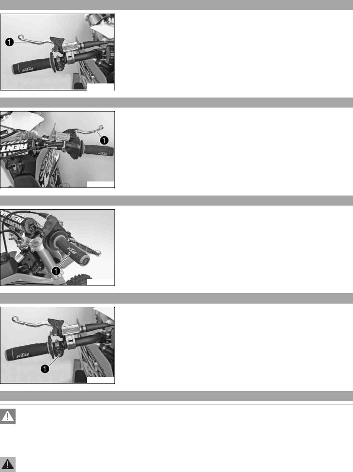
Clutch5.1 lever
The clutch lever is fitted on the left side of the handlebar.
The clutch is hydraulically operated and self-adjusting.
C00038-10
Hand5.2 brake lever
Hand brake lever is fitted on the right side of the handlebar.
The hand brake lever is used to activate the front brake.
C00030-10
Throttle5.3 grip
Throttle grip is fitted on the right side of the handlebar.
C00027-10
Kill5.4 switch
Kill switch is fitted on the left side of the handlebar.
Possible states
•Kill switch  in basic position – In this position, the ignition circuit is closed, and the engine can be started.
•Kill switch  pressed – In this position, the ignition circuit is interrupted, a running engine stops, and a non-running engine will not start.
C00039-10
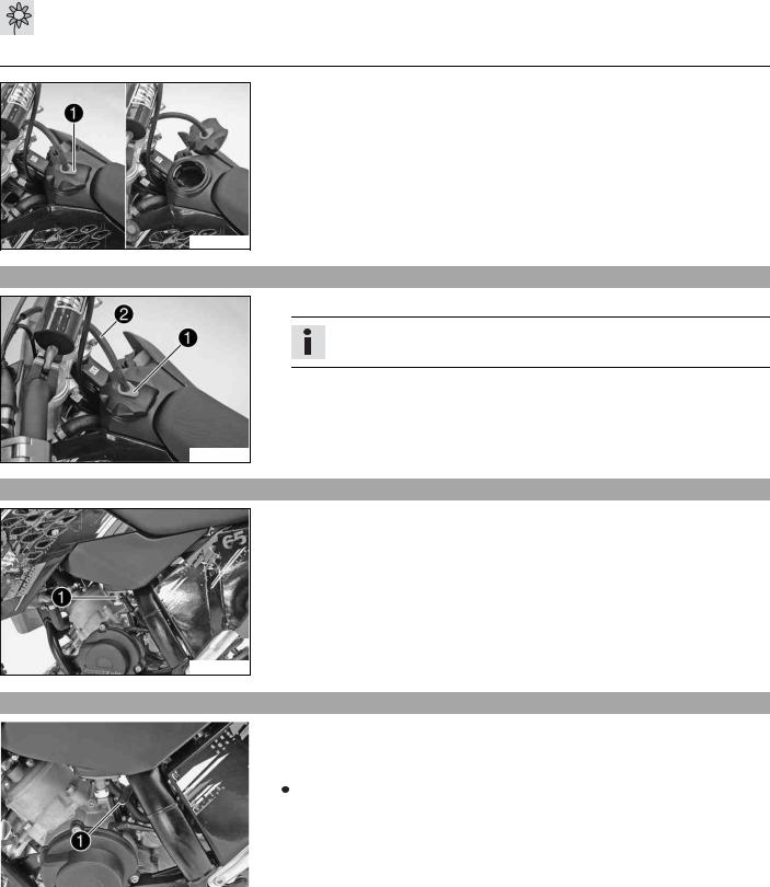
Opening5.5 the filler cap
Danger
Fire hazard Fuel is highly flammable.
–Never refuel the vehicle near open flames or burning cigarettes, and always switch off the engine first. Be careful that no fuel is spilt, especially on hot vehicle components. Clean up spilt fuel immediately.
–Fuel in the fuel tank expands when warm and can escape if the tank is overfilled. See the notes on refueling.
Warning
Danger of poisoning Fuel is poisonous and a health hazard.
–Avoid contact between fuel and skin, eyes and clothing. Do not inhale fuel vapors. If fuel gets into your eyes, rinse immediately with water and contact a doctor. Wash affected skin areas immediately with soap and water. If fuel is swallowed, contact a doctor immediately. Change clothing that has come into contact with fuel. Store fuel in a suitable canister according to regulations and keep it out of the reach of children.
CONTROLS |
11 |
Warning
Environmental hazard Improper handling of fuel is a danger to the environment.
–Do not allow fuel to get into the ground water, the ground, or the sewage system.
–Press release button , turn the filler cap counterclockwise, and lift it free.
700396-01
Closing5.6 the filler cap
–Replace the filler cap and turn clockwise until the release button locks in place.
Info
Run the fuel tank breather hose without kinks.
700397-01
Fuel5.7 tap
Fuel tap is on the left of the fuel tank.
Possible states
•Fuel tap is closed – The knurled screw is turned all the way clockwise. Fuel cannot flow out of the fuel tank.
•Fuel tap is open – The knurled screw is turned all the way counterclockwise. Fuel can flow out of the fuel tank.
700407-01
Choke5.8
|
|
|
Choke lever is fitted on the left side of the carburetor. |
|||
|
|
|||||
|
|
|
Activating the choke function frees an opening through which the engine can draw |
|||
|
|
|
extra fuel. This gives a richer fuel-air mixture, which is needed for a cold start. |
|||
|
|
|
|
|
|
|
|
|
|
|
|
|
Info |
|
|
|
|
|
|
|
|
|
|
|
|
|
If the engine is warm, the choke function must be deactivated. |
|
|
|
|
|||
|
|
|
Possible states |
|||
|
|
|
• Choke function activated – The choke lever is pushed down all the way. |
|||
|
|
|
• Choke function deactivated – The choke lever is pushed up all the way. |
|||
|
700402-01 |
|||||
|
|
|
|
|
|
|
CONTROLS |
12 |
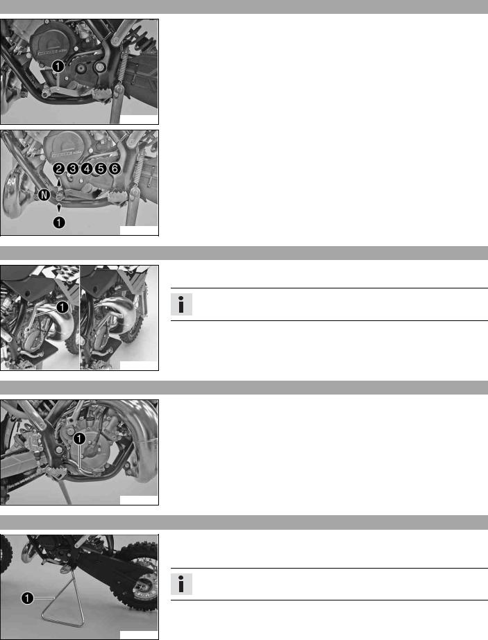
Shift5.9 lever
Shift lever is mounted on the left side of the engine.
700398-01
The gear positions can be seen in the photograph.
The neutral or idle position is between the first and second gears.
700399-01
Kickstarter5.10
The kickstarter is fitted on the right of the engine.
The kickstarter can be swiveled.
Info
Before riding, swing the kickstarter inwards towards the engine.
C00040-10
Foot5.11 brake lever
Foot brake lever is located in front of the right footrest.
The foot brake lever is used to activate the rear brake.
700400-01
Plug5.12 -in stand
The fixture for the plug-in stand is located on the frame on the left side of the vehicle.
The plug-in stand is used to park the motorcycle.
Info
Remove the plug-in stand before riding.
700406-01
PUTTING INTO OPERATION |
13 |
Advice6.1 on first use
Warning
Danger of accidents Physical and mental readiness of a child.
–Your child must be able to ride a bicycle and must be able to erect the vehicle independently after a fall. In addition, your child must understand the regulations and instructions from you or from other guardians. Do not ask too much of your child; participation in competitive activities should not be considered until your child's stamina, riding techniques and motivation are at the necessary levels. Children often underestimate or fail to recognize dangerous situations; make it clear to your child that it should not, under any circumstances, operate the vehicle without supervision and that your child may only drive at speeds that are commensurate with the child's riding abilities and the road conditions.
–Only let your child ride on the vehicle if it is physically and mentally ready to operate the vehicle.
Warning
Risk of injury Missing or poor protective clothing present an increased safety risk.
–Wear protective clothing (helmet, boots, gloves, pants and jacket with protectors) every time you ride the motorcycle. You and your child should always used protective clothing that is in good condition and meets the legal requirements. When you ride a motorcycle, set an example for your child and wear suitable protective clothing.
Warning
Danger of crashing Poor vehicle handling due to different tire tread patterns on front and rear wheels.
–The front and rear wheels must be fitted with tires with similar tread patterns to prevent loss of control over the vehicle.
Warning
Danger of accidents Critical riding behavior due to inappropriate riding.
–Ensure that your child adjusts the riding speed to the road conditions and to his or her riding abilities.
Warning
Danger of accidents Accident risk caused by presence of a passenger.
–Your vehicle is not designed to carry passengers. Do not ride with a passenger.
Warning
Danger of accidents Brake system failure.
–If the foot brake lever is not released, the brake linings drag permanently. The rear brake can fail due to overheating. Ensure that your child raises his or her foot from the foot brake lever when the child does not want to brake.
Warning
Danger of accidents Destruction of chassis components.
–Do not exceed the maximum allowable rider weight.
Warning
Risk of misappropriation Usage by unauthorized persons.
–Never leave the vehicle while the engine is running. Secure the vehicle against use by unauthorized persons.
Info
When using your motorcycle, remember that others may feel disturbed by excessive noise.
–Make sure that the pre-delivery inspection work has been carried out by an authorized KTM workshop.  You receive a delivery certificate and the service record at vehicle handover.
–Carefully read the entire owner's manual together with your child before going for the first ride.
Info
Pay special attention to the safety warnings and injury risks.
Explain to your child the techniques of riding and falling, e.g. how shifting weight can influence handling characteristics.
–Familiarize your child with the controls.
–Adjust the basic position of clutch lever. ( p. 43)
–Adjust the basic position of the hand brake lever. ( p. 45)
–Adjust the basic position of the foot brake lever. x( p. 50)
–Before using the vehicle for the first time, ensure that the basic settings of the chassis are suitable for the weight of your child.
PUTTING INTO OPERATION |
14 |
–Accustom your child to the handling of the motorcycle on suitable terrain, preferably on a large open meadow.
Info
To give your child a feel for the brake, you should push your child at first. Do not start the engine until your child is able to apply the necessary brake pressure.
Initially, let your child drive to another person who can help your child stop and turn.
–Erect obstacles for your child to navigate around to accustom your child to handling the vehicle.
–Your child should also try to ride as slowly as possible and in a standing position to get a better feeling for the vehicle.
–Do not let your child ride on terrain that exceed your child's capabilities and experience.
–Your child should hold the handlebar firmly with both hands and keep his or her feet on the footrests when riding.
–Do not exceed the maximum allowable rider weight. Guideline
Maximum rider weight |
< 50 kg (< 110 lb.) |
|
|
–Check the spoke tension. ( p. 57)
Info
The spoke tension must be checked after riding the motorcycle for half an hour.
–Run the engine in. ( p. 14)
Running6.2 in the engine
–During the running-in phase, do not exceed the specified engine performance. Guideline
Maximum engine performance
During the first 3 service hours |
< 70 % |
|
|
During the first 5 service hours |
< 100 % |
|
|
– Avoid fully opening the throttle!
RIDING INSTRUCTIONS |
15 |
Checks7.1 and maintenance measures when preparing for use
Info
Before each use, check the condition of the vehicle and its operating safety.
The vehicle must be in perfect technical condition when it is being operated.
–Check the gear oil level. ( p. 64)
–Check the front brake brake fluid level. ( p. 46)
–Check the rear brake fluid level. ( p. 50)
–Check the front brake linings. ( p. 47)
–Check the rear brake linings. ( p. 52)
–Check the brake system function.
–Check the coolant level. ( p. 60)
–Check the chain dirt accumulation. ( p. 39)
–Check the chain, rear sprocket, engine sprocket, and chain guide. ( p. 40)
–Check the chain tension. ( p. 39)
–Check the tire condition. ( p. 57)
–Check the tire air pressure. ( p. 57)
–Check the spoke tension. ( p. 57)
–Clean the dust boots of the fork legs. ( p. 26)
–Bleed fork legs. ( p. 26)
–Check the air filter.
–Check the settings of all controls and ensure that they can be operated smoothly.
–Check all screws, nuts and hose clamps regularly for tightness.
–Check the fuel supply.
Starting7.2
Danger
Danger of poisoning Exhaust gases are poisonous and inhaling them may result in unconsciousness and/or death.
–When running the engine, always make sure there is sufficient ventilation, and do not start or run the engine in an enclosed space without an effective exhaust extraction system.
Note
Engine failure High engine speeds in cold engines have a negative effect on the service life of the engine.
–Always warm up the engine at low engine speeds.
Info
If the motorcycle is unwilling to start, the cause can be old fuel in the float chamber. The flammable elements of the fuel evaporate after a long time of standing.
If the float chamber is filled with fresh fuel, the engine starts immediately.
Engine has been out of use for more than 1 week
– Empty the carburetor float chamber. x( p. 63)
–Turn the knurled screw on the fuel tap all the way counterclockwise.  Fuel can flow from the fuel tank to the carburetor.
–Remove the motorcycle from the stand.
–Shift gear to neutral.
The engine is cold
– Push the choke lever down all the way.
–Forcefully step on the kickstarter, pushing it all the way down.
Info
Do not open the throttle.
RIDING INSTRUCTIONS |
16 |
Starting7.3 off
Info
The plug-in stand must be removed prior to riding.
–Pull the clutch lever, engage 1st gear, release the clutch lever slowly and simultaneously open the throttle carefully.
Shifting,7.4 riding
Warning
Danger of accidents If you change down at high engine speed, the rear wheel can lock up.
–Do not change into a low gear at high engine speed. The engine races and the rear wheel can lock up.
Info
If you hear unusual noises while riding, stop immediately, switch off the engine and contact an authorized KTM workshop. First gear is used for starting off or for steep inclines.
–When conditions allow (incline, road situation, etc.), your child can shift into a higher gear. To do so, release the throttle while simultaneously pulling the clutch lever, shift into the next gear, release the clutch and open the throttle.
–If the choke function was activated, deactivate it after the engine has warmed up.
–When you reach maximum speed after fully opening the throttle, turn back the throttle to about ¾ of its range. The speed hardly drops, but the fuel consumption falls considerably.
–Your child should always open the throttle only as much as the engine can handle – abruptly opening the throttle increases fuel consumption.
–To shift down, brake and close the throttle at the same time.
–Pull the clutch lever and shift into a lower gear, release the clutch lever slowly and open the throttle or shift again.
–Your child should switch off the engine if he or she expects to be standing for a long time. Guideline
≥2 min
–Your child should avoid frequent and extended slipping of the clutch. This heats the engine oil, the engine and the cooling system.
–Insist that your child ride with a low rpm instead of with a high rpm and a slipping clutch.
Braking7.5
Warning
Danger of accidents If you brake too hard, the wheels can lock.
–Adapt your braking to the traffic situation and the road conditions.
Warning
Danger of accidents Reduced braking efficiency caused by spongy pressure point of front or rear brake.
–Check the brake system and do not continue riding. (Your authorized KTM workshop will be glad to help.)
Warning
Danger of accidents Reduced braking efficiency due to wet or dirty brakes.
–Clean or dry dirty or wet brakes by riding and braking gently.
–On sandy, wet or slippery surfaces, use the rear brake.
–Braking should always be completed before you go into a bend. Your child should change down to a lower gear appropriate to the road speed.
–Insist that your child take advantage of the braking action of the engine when riding on long downhills. To do so, shift back one or two gears, but do not overrev the engine. Your child will need to apply the brakes far less often and the brakes are not overheated.
RIDING INSTRUCTIONS |
17 |
Stopping,7.6 parking
Warning
Risk of misappropriation Usage by unauthorized persons.
–Never leave the vehicle while the engine is running. Secure the vehicle against use by unauthorized persons.
Warning
Danger of burns Some vehicle components become very hot when the vehicle is operated.
–Do not touch hot components such as exhaust system, radiator, engine, shock absorber and brakes. Allow these components to cool down before starting work on them.
Note
Danger of damage The parked vehicle may roll away or fall over.
–Always place the vehicle on a firm and even surface.
Note
Fire hazard Some vehicle components become very hot when the vehicle is operated.
–Do not park the vehicle near flammable or explosive substances. Do not place objects on the vehicle while it is still warm from being run. Always let the vehicle cool first.
Note
Material damage Damage and destruction of components by excessive load.
–The side stand is designed for the weight of the motorcycle only. Do not sit on the motorcycle when it is supported by the side stand only. The side stand and/or the frame could be damaged and the motorcycle could fall over.
–Brake the motorcycle.
–Shift gear to neutral.
–Press and hold the kill switch  while the engine is idling until the engine stops.
–Turn the knurled screw on the fuel tap all the way clockwise.
–Park the motorcycle on firm ground.
Refueling7.7
Danger
Fire hazard Fuel is highly flammable.
–Never refuel the vehicle near open flames or burning cigarettes, and always switch off the engine first. Be careful that no fuel is spilt, especially on hot vehicle components. Clean up spilt fuel immediately.
–Fuel in the fuel tank expands when warm and can escape if the tank is overfilled. See the notes on refueling.
Warning
Danger of poisoning Fuel is poisonous and a health hazard.
–Avoid contact of the fuel with skin, eyes and clothing. Do not inhale fuel vapors. If fuel gets into your eyes, rinse immediately with water and contact a doctor. Wash affected skin areas immediately with soap and water. If fuel is swallowed, contact a doctor immediately. Change clothing that has come into contact with fuel.
Warning
Environmental hazard Improper handling of fuel is a danger to the environment.
–Do not allow fuel to get into the ground water, the ground, or the sewage system.
–Switch off the engine.
–Open the filler cap. ( p. 10)
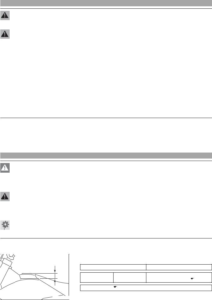
|
– Fill the fuel tank with fuel up to measurement . |
|
||
|
Guideline |
|
|
|
|
Measurement of |
|
35 mm (1.38 in) |
|
A |
Fuel tank capac- |
3.5 l (3.7 qt.) |
Super unleaded gasoline, mixed with |
|
|
ity, approx. |
|
2-stroke engine oil (1:60) ( |
p. 80) |
|
2-stroke engine oil ( |
p. 79) |
|
|
400382-10 |
|
|
|
|
RIDING INSTRUCTIONS |
18 |
–Close the filler cap. ( p. 11)
|
SERVICE SCHEDULE |
|
|
|
|
|
|
19 |
|
|||
|
|
|
|
|
|
|
|
|
|
|
|
|
|
Service8.1 |
schedule |
|
|
|
|
|
|
|
|
|
|
|
|
|
|
|
|
|
|
|
|
|
|
|
|
|
|
|
|
|
|
S10N |
S20A |
S40A |
S80A |
J1A |
|
|
|
|
|
|
|
|
|
|
|
|
||
|
Change the gear oil. x( |
p. 64) |
|
|
• |
|
• |
• |
|
|
||
|
Check the gear oil level. ( |
p. 64) |
|
|
|
• |
• |
• |
|
|
||
|
|
|
|
|
|
|
|
|
|
|
||
|
Check the front brake linings. ( |
p. 47) |
|
|
• |
• |
• |
• |
|
|
||
|
|
|
|
|
|
|
|
|
|
|
||
|
Check the rear brake linings. ( |
p. 52) |
|
|
• |
• |
• |
• |
|
|
||
|
|
|
|
|
|
|
|
|
|
|
||
|
Check the brake discs. ( |
p. 45) |
|
|
• |
• |
• |
• |
|
|
||
|
|
|
|
|
|
|
|
|
||||
|
Check brake lines for damage and leakage. |
|
• |
• |
• |
• |
|
|
||||
|
|
|
|
|
|
|
|
|||||
|
Change the sealing sleeves of the foot brake cylinder. x |
|
• |
• |
• |
|
|
|||||
|
|
|
|
|
|
|
|
|
|
|
||
|
Change the rear brake fluid. x |
|
|
|
|
|
|
|
• |
|
||
|
Check the rear brake fluid level. ( p. 50) |
|
• |
• |
• |
• |
|
|
||||
|
|
|
|
|
|
|
|
|
||||
|
Check the free travel of the foot brake lever. ( |
p. 49) |
• |
• |
• |
• |
|
|
||||
|
|
|
|
|
|
|
|
|
|
|||
|
Check the frame and swingarm. x |
|
|
|
• |
• |
• |
|
|
|||
|
Check swingarm bearing. x |
|
|
|
|
• |
• |
• |
|
|
||
|
Check the heim joints on the upper and lower shock absorbers. x |
|
• |
• |
• |
|
|
|||||
|
|
|
|
|
|
|
|
|
|
|
|
|
|
Service the fork. x |
|
|
|
|
|
|
• |
• |
|
|
|
|
Service the shock absorber. x |
|
|
|
|
|
• |
• |
|
|
||
|
Check the tire condition. ( |
p. 57) |
|
|
• |
• |
• |
• |
|
|
||
|
|
|
|
|
|
|
|
|
|
|
||
|
Check the tire air pressure. ( |
p. 57) |
|
|
• |
• |
• |
• |
|
|
||
|
|
|
|
|
|
|
|
|
|
|||
|
Check wheel bearing for play. x |
|
|
|
• |
• |
• |
|
|
|||
|
Check the wheel hub. x |
|
|
|
|
|
• |
• |
• |
|
|
|
|
|
|
|
|
|
|
|
|
|
|
|
|
|
Check rim run-out. x |
|
|
|
|
• |
• |
• |
• |
|
|
|
|
Check the spoke tension. ( |
p. 57) |
|
|
• |
• |
• |
• |
|
|
||
|
|
|
|
|
|
|
|
|||||
|
Check the chain, rear sprocket, engine sprocket, and chain guide. ( p. 40) |
• |
• |
• |
• |
|
|
|||||
|
|
|
|
|
|
|
|
|
|
|
||
|
Check the chain tension. ( |
p. 39) |
|
|
• |
• |
• |
• |
|
|
||
|
|
|
|
|
|
|
|
|||||
|
Lubricate all moving parts (e. g. hand levers, chain, ...) and check for smooth opera- |
• |
• |
• |
• |
|
|
|||||
|
tion. x |
|
|
|
|
|
|
|
||||
|
|
|
|
|
|
|
|
|
|
|
|
|
|
Change the hydraulic clutch fluid. x( |
p. 44) |
|
|
|
|
|
• |
|
|||
|
Check the fluid level of the hydraulic clutch. ( |
p. 44) |
• |
• |
• |
• |
|
|
||||
|
|
|
|
|
|
|
|
|
|
|||
|
Change the front brake fluid. x |
|
|
|
|
|
|
• |
|
|||
|
Check the front brake brake fluid level. ( |
p. 46) |
• |
• |
• |
• |
|
|
||||
|
|
|
|
|
|
|
|
|
||||
|
Check the free travel of the hand brake lever. ( |
p. 45) |
• |
• |
• |
• |
|
|
||||
|
|
|
|
|
|
|
|
|
|
|||
|
Grease the steering head bearing. x( |
p. 32) |
|
|
|
|
|
• |
|
|||
|
Check play of steering head bearing. ( |
p. 31) |
|
• |
• |
• |
• |
|
|
|||
|
|
|
|
|
|
|
|
|
||||
|
Change the spring of the exhaust control. x |
|
|
|
• |
• |
|
|
||||
|
|
|
|
|
|
|
|
|
|
|
|
|
|
Change the piston. x |
|
|
|
|
|
|
• |
• |
|
|
|
|
Change the connecting rod, conrod bearing and crank pin. x |
|
|
• |
• |
|
|
|||||
|
Change the crankshaft bearing. x |
|
|
|
|
• |
• |
|
|
|||
|
|
|
|
|
|
|
|
|||||
|
Check the transmission and shift mechanism. x |
|
|
• |
• |
|
|
|||||
|
Change all engine bearings. x |
|
|
|
|
|
|
• |
|
|
||
|
Change the spark plug. x |
|
|
|
|
|
• |
• |
• |
|
|
|
|
|
|
|
|
|
|
|
|
|
|||
|
Change the spark plug connector. x |
|
|
|
|
• |
• |
|
|
|||
|
Check the cylinder and piston. x |
|
|
|
• |
• |
• |
|
|
|||
|
Check the intake membrane. x |
|
|
|
• |
• |
• |
|
|
|||
|
|
|
|
|
|
|
|
|||||
|
Check the exhaust control for functioning and smooth operation. x |
|
• |
• |
• |
|
|
|||||
|
Check the clutch. x |
|
|
|
|
|
• |
• |
• |
|
|
|
|
Check all hoses (e. g. fuel, cooling, bleeding, drainage) and sleeves for tearing, tight- |
• |
• |
• |
• |
|
|
|||||
|
ness and correct routing. x |
|
|
|
|
|
||||||
|
|
|
|
|
|
|
|
|
|
|||
|
|
|
|
|
|
|
|
|
||||
|
Check the antifreeze and coolant level. ( |
p. 59) |
• |
• |
• |
• |
|
|
||||
|
|
|
|
|
|
|
|
|||||
|
Check the cables for damage and routing without sharp bends. x |
• |
• |
• |
• |
|
|
|||||
|
Check the cables for damage, routing without sharp bends and correct adjustment. |
• |
• |
• |
• |
|
|
|||||
|
|
|
|
|
|
|
|
|
|
|
|
|
|
SERVICE SCHEDULE |
|
|
|
|
20 |
|
|
|
|
|
|
|
|
|
|
|
S10N |
S20A |
S40A |
S80A |
J1A |
|
|
|
|
|
|
|
|
|
|
Clean the air filter and air filter box. x( p. 35) |
• |
• |
• |
• |
|
|
|
Change the glass fiber yarn filling of the main silencer. x( p. 36) |
|
• |
• |
• |
|
|
|
|
|
|
|
|
|
|
|
Check the screws and nuts for tightness. x |
• |
• |
• |
• |
|
|
|
Check/set the carburetor components. x |
|
|
• |
• |
• |
|
|
Check idle. x |
• |
• |
• |
• |
|
|
|
|
|
|
|
|
|
|
|
Final inspection: check the vehicle for operating safety and take a test ride. |
• |
• |
• |
• |
|
|
|
|
|
|
|
|
|
|
|
Create a service entry in the KTM DEALER.NET and in the service record. x |
• |
• |
• |
• |
|
|
|
|
|
|
|
|
|
|
S10N: Once after 10 operating hours
S20A: Every 20 operating hours
S40A: Every 40 operating hours
S80A: Every 80 operating hours
J1A: Annually
TUNING THE CHASSIS |
21 |
Adjusting9.1 the compression damping of the fork
Info
The hydraulic compression damping determines the fork suspension behavior.
|
|
– Turn adjusting screw clockwise all the way. |
|||||
|
|
||||||
|
|
|
|
|
|
|
|
|
|
|
|
|
|
Info |
|
|
|
|
|
|
|
|
|
|
|
|
|
|
|
Adjusting screw is located at the top end of the right fork leg and is |
|
|
|
|
|
|
|
labeled with a COM. |
|
|
|
|
|
|
|||
|
|
– Turn back counterclockwise by the number of clicks corresponding to the fork type. |
|||||
|
|
|
Guideline |
|
|||
|
|
|
|
|
|||
|
|
|
Compression damping |
|
|||
|
|
|
|
|
|
|
|
|
C00002-10 |
|
|
|
Standard |
2 turns |
|
|
|
|
|
|
|
|
|
|
|
|
|
|
|
|
|
Info
Turn clockwise to increase damping; turn counterclockwise to reduce damping.
Adjusting9.2 the rebound damping of the fork
Info
The hydraulic rebound damping determines the fork suspension behavior.
|
|
– Turn adjusting screw clockwise all the way. |
|||||
|
|
||||||
|
|
|
|
|
|
|
|
|
|
|
|
|
|
Info |
|
|
|
|
|
|
|
|
|
|
|
|
|
|
|
Adjusting screw is located at the top end of the left fork leg and is |
|
|
|
|
|
|
|
labeled with a REB. |
|
|
|
|
|
|
|||
|
|
– Turn back counterclockwise by the number of clicks corresponding to the fork type. |
|||||
|
|
|
Guideline |
|
|||
|
|
|
|
|
|||
|
|
|
Rebound damping |
|
|||
|
|
|
|
|
|
|
|
|
C00003-10 |
|
|
|
Standard |
2 turns |
|
|
|
|
|
|
|
|
|
|
|
|
|
|
|
|
|
Info
Turn clockwise to increase damping; turn counterclockwise to reduce damping.
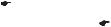
Adjusting9.3 the compression damping of the shock absorber
Caution
Danger of accidents Disassembly of pressurized parts can lead to injury.
–The shock absorber is filled with high density nitrogen. Adhere to the description provided. (Your authorized KTM workshop will be glad to help.)
–Turn adjusting knob counterclockwise all the way.
–Turn clockwise by the number of clicks corresponding to the shock absorber type. Guideline
Compression damping
Standard |
6 clicks |
|
|
|
|
|
Info |
|
Turn counterclockwise to increase damping; turn clockwise to reduce damp- |
700409-01 |
ing. |
TUNING THE CHASSIS |
22 |
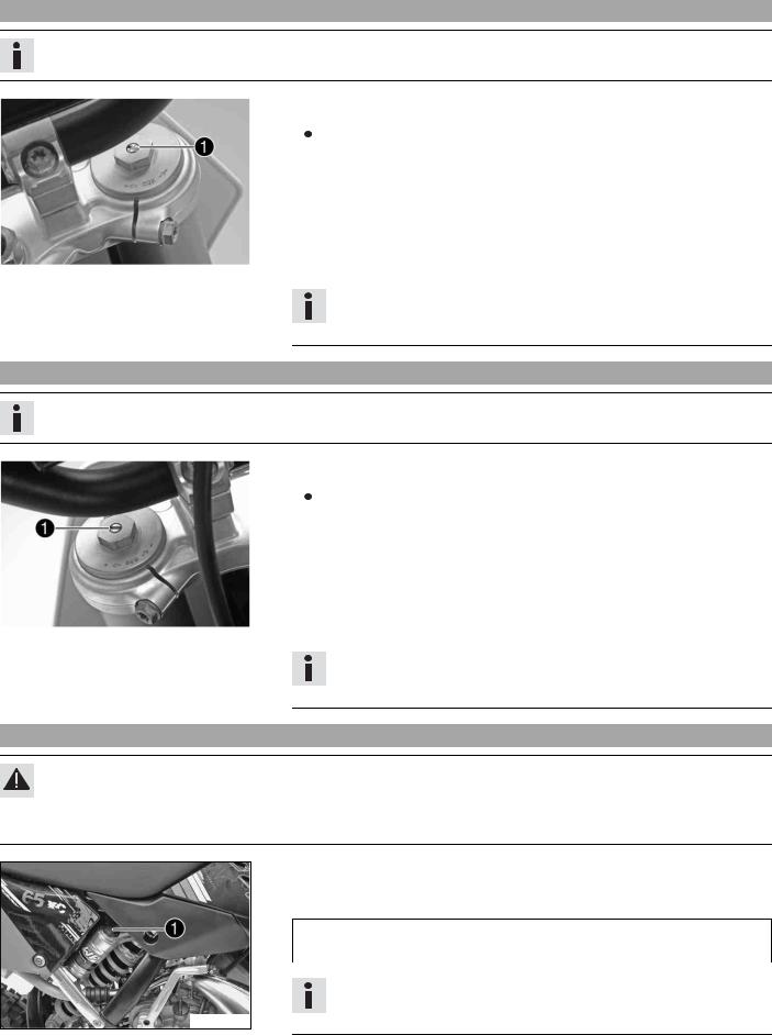
Adjusting9.4 the rebound damping of the shock absorber
Caution
Danger of accidents Disassembly of pressurized parts can lead to injury.
–The shock absorber is filled with high density nitrogen. Adhere to the description provided. (Your authorized KTM workshop will be glad to help.)
–Turn adjusting screw clockwise up to the last perceptible click.
–Turn back counterclockwise by the number of clicks corresponding to the shock absorber type.
Guideline
Rebound damping
Standard |
12 clicks |
|
|
|
|
|
|
|
|
|
|
|
Info |
|
|
|
|
|
|
|
|
|
|
|
|
|
|
|
Turn clockwise to increase damping; turn counterclockwise to reduce damp- |
|
700410-01 |
||||||
|
|
|
|
|
|
|
ing. |
|
|
|
|
|
|
|
|
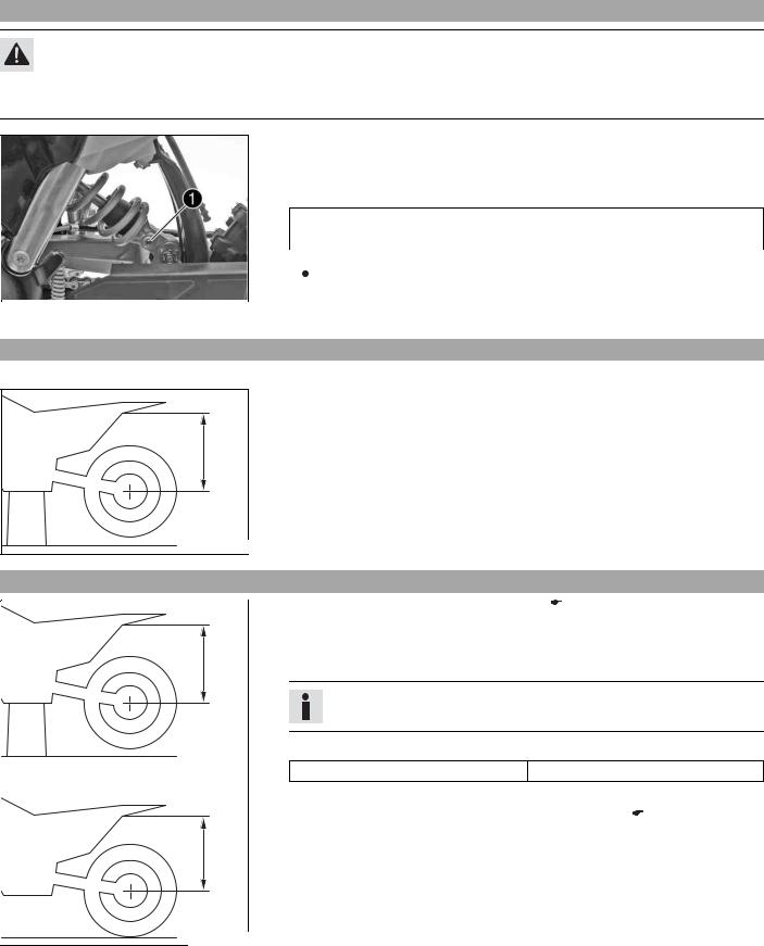
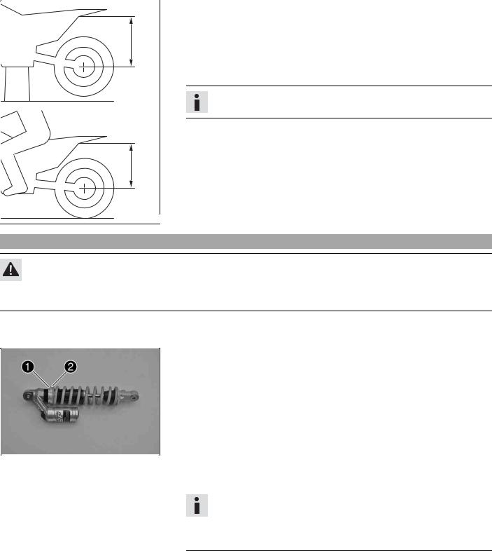
Measuring9.5 rear wheel sag unloaded
0A |
400988-10 |
–Raise the motorcycle with a lift stand. ( p. 26)
–Measure the distance – as vertical as possible – between the rear axle and a fixed point, for example, a mark on the side cover.
–Make a note of the value as measurement .
–Remove the motorcycle from the lift stand. ( p. 26)
Checking9.6 |
the static sag of the shock absorber |
|
|
|
||
|
|
– |
Measure distance of rear wheel unloaded. ( |
p. 22) |
|
|
|
|
– Hold the motorcycle in a vertical position with the assistance of another person. |
||||
|
0A |
– Measure the distance between the rear axle and the fixed point again. |
||||
|
– |
Make a note of the value as measurement . |
|
|
||
|
|
|
Info |
|
|
|
|
|
|
The static sag is the difference between measurements and . |
|||
|
|
– Check the static sag. |
|
|
|
|
|
|
|
Static sag |
33 mm (1.3 in) |
|
|
|
|
|
» If the static sag is less or more than the specified value: |
|
||
|
|
|
– Adjust the spring preload of the shock absorber. x( |
p. 23) |
||
|
0B |
|
|
|
|
|
|
400989-10 |
|
|
|
|
|
|
TUNING THE CHASSIS |
23 |
||
|
|
|
|
|
|
Checking9.7 |
the riding sag of the shock absorber |
|
|
0A |
0C |
400990-10 |
–Measure distance of rear wheel unloaded. ( p. 22)
–With another person holding the motorcycle, the rider sits down on the saddle in full protective clothing in a normal sitting position (feet on footrests) and bounces up and down a few times.
 The rear wheel suspension levels out.
–Another person now measures the distance between the rear axle and a fixed point.
–Make a note of the value as measurement .
Info
The riding sag is the difference between measurements and .
–Check the riding sag.
Riding sag |
90 mm (3.54 in) |
|
|
»If the riding sag differs from the specified measurement:
– Adjust the riding sag. x( p. 24)
Adjusting9.8 the spring preload of the shock absorber x
Caution
Danger of accidents Disassembly of pressurized parts can lead to injury.
–The shock absorber is filled with high density nitrogen. Adhere to the description provided. (Your authorized KTM workshop will be glad to help.)
–Remove shock absorber. x( p. 33)
–After removing the shock absorber, clean it thoroughly.
–Measure the full spring length while it is under tension and note down the value.
–Loosen retaining ring .
–Turn adjusting ring until the spring is no longer under tension.
|
|
|
|
Combination wrench (50329080000) |
|
|
|
|
|
|
|
|
|
|
|
Hook wrench (T106S) |
|
|
|
|
|
|
|
|
|
|
– Measure the overall spring length when not under tension. |
||
|
|
|
– Tighten the spring by turning adjusting ring to the specified measurement. |
||
|
|
|
|
Guideline |
|
|
700449-01 |
|
|||
|
|
|
|
|
|
|
|
|
|
Spring preload |
|
|
|
|
|
|
|
|
|
|
|
Standard |
7 mm (0.28 in) |
|
|
|
|
|
|
|
|
|
|
|
|
Info
The spring preload is the difference between the relaxed spring length and the tensioned spring length.
Depending on the static sag and/or the riding sag, it may be necessary to increase or decrease the spring preload.
–Tighten retaining ring .
–Install the shock absorber. x( p. 33)
TUNING THE CHASSIS |
24 |
Adjusting9.9 the riding sag x
–Remove shock absorber. x( p. 33)
–After removing the shock absorber, clean it thoroughly.
–Choose and mount a suitable spring.
Guideline
Spring rate
Weight of rider: < 35 kg (< 77 lb.) |
35 N/mm (200 lb/in) |
|
|
Weight of rider: 35… 45 kg (77… |
40 N/mm (228 lb/in) |
99 lb.) |
|
|
|
Weight of rider: > 45 kg (> 99 lb.) |
45 N/mm (257 lb/in) |
|
|
|
|
B00292-10 |
Info |
The spring rate is shown on the outside of the spring.
Smaller weight differences can be compensated by changing the spring preload.
–Install the shock absorber. x( p. 33)
–Check the static sag of the shock absorber. ( p. 22)
–Check the riding sag of the shock absorber. ( p. 23)
–Adjust the rebound damping of the shock absorber. ( p. 22)
Handlebar9.10 position
0A 


 0B
0B
On the upper triple clamp, there are 2 holes at a distance of to each other.
Distance between holes 15 mm (0.59 in)
The holes on the handlebar support are placed at a distance of from the center.
Distance between holes |
3.5 mm (0.138 in) |
|
|
The handlebar supports can be mounted in 4 different positions.
400271-11
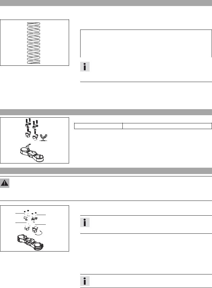
Adjusting9.11 handlebar position x
Warning
Danger of accidents Handlebar breakage.
–If the handlebar is bent or straightened it will cause material fatigue, and the handlebar can break. Always replace handlebar.
1 


 10 02
10 02 


 20
20
–Remove the four screws . Remove the handlebar clamp. Remove the handlebar and lay it to one side.
Info
Protect the motorcycle and its attachments from damage by covering them.
Do not bend the cables and lines.
–Remove the two screws . Remove the handlebar support.
–Place the handlebar support in the required position. Mount and tighten the two
B00375-10 |
|
screws . |
|
|
|
|
Guideline |
|
|
||
|
|
|
|
||
|
|
|
|
|
|
|
|
Screw, handlebar support |
M10 |
40 Nm |
Loctite® 243™ |
|
|
|
|
(29.5 lbf ft) |
|
|
|
|
|
|
|
|
– Position the handlebar. |
|
|
||
Info
Make sure cables and wiring are positioned correctly.

TUNING THE CHASSIS |
25 |
–Position the handlebar clamp. Mount and evenly tighten the four screws . Guideline
Screw, handlebar clamp |
M8 |
20 Nm |
|
|
(14.8 lbf ft) |
|
|
|
|
|
|
Info
Make sure the gap width is even.
 Loading...