


English
Français Deutsch
Italiano
Nederlands Svensk Português Español
www.midwestelectronics.com

BLAUPUNKT SPECIFICATIONS - VA4100, 4/3/2 CHANNEL AMPLIFIER
All power ratings conform to CEA-2006 standards.
PARAMETER/FEATURE |
|
VA4100 |
Channels |
|
4/3/2 |
|
|
|
Size ( L x W x D) without trim panels |
|
15.1x9.1x2.4 inches (382x231x60mm) |
|
|
|
Weight |
|
14.5 lbs. (6.6 kg) |
|
|
|
Spade screw speaker terminals? |
|
YES |
|
|
|
Maximum terminal wire size |
|
10 ga. |
|
|
|
Subsonic filter |
|
YES (10 Hz) |
|
|
|
Separate front/rear or left/right gains? |
|
F/R-YES L/R-NO |
|
|
|
Fuse Type |
|
ATC spade -Two 40A |
|
|
|
Speaker short, short to +12V, and short to ground protection? |
YES |
|
|
|
|
High, low, and reverse voltage protection? |
|
YES |
|
|
|
Power output transistors |
|
Low QZ MOSFET |
|
|
|
Power supply transistors |
|
MOSFET |
|
|
|
Minimum speaker impedance |
(non-bridged) |
2 ohms |
|
|
|
|
(bridged) |
4 ohms |
|
|
|
PERFORMANCE DATA |
|
|
Rated power output @ 0.1% THD, 14.4V (CEA-2006) |
|
|
|
|
|
4 channels into 4 ohms / 2 ohms |
(watts rms) |
4 x 100 W / 4 x 150 W |
|
|
|
2 channels into 4 ohms |
(watts rms) |
2 x 300 W |
|
|
|
Max Dynamic Power (watts rms) |
|
700W |
|
|
|
Total Harmonic Distortion @ full power |
|
0.1% THD |
|
|
|
Signal/Noise ratio (gain controls in center) |
|
|
|
|
|
Measured @ 1 watt / 1 kHz |
dBA |
>80 |
|
|
|
Measured @ full rated power (0.1% THD) |
dBA |
>100 |
|
|
|
Damping factor |
|
>100 |
|
|
|
Frequency response (full-range mode) |
|
15 - 50,000 Hz |
|
|
|
High-pass crossover frequency limits |
|
50 H z - 250 Hz (variable), 12dB/oct |
|
|
|
Low-pass crossover frequency limits |
|
50 H z - 250 Hz (variable), 12dB/oct |
|
|
|
Input impedance |
|
10 kohms |
|
|
|
Input signal voltage control range |
|
0.3 - 6.0 vrms |
|
|
|
Current Draw @ 13.8 VDC (typical values @ X watts / Efficiency %) |
|
|
|
|
|
@ full rated power, unbridged |
(@ 4 ohms) |
50 A (50%) |
|
|
|
@ 33% rated power, unbridged |
(@ 4 ohms) |
30 A (35%) |
|
|
|
@ idle |
(@ 4 ohms) |
1 A |
|
|
|
Minimum battery voltage to maintain rated power |
12.6 VDC |
|
|
|
|
Usable battery voltage |
|
10 - 16 VDC |
|
|
|
Trigger line voltage range |
|
10 - 16 VDC |
|
|
|
Trigger line current draw |
|
< 20 mA |
|
|
|
Turn on delay time |
|
@ 2.0 seconds |
|
|
|
Thermal shutoff temperature (average heat-sink temp) |
@ 85˚ C (185˚ F) |
|
|
|
|
This information is subject to change without notice! • Änderungen vorbehalten! • Sous réserve de modifications!
Modifiche riservate! • Wijzigingen voorbehouden! • Ändringar förbehålles! • Modificaciones reservadas! • Sob reserva de alterações!
– 1 –
www.midwestelectronics.com
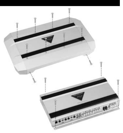
ASSEMBLY & MOUNTING
– 2 –
www.midwestelectronics.com
THANK YOU FOR CHOOSING BLAUPUNKT!
Congratulations! You are the now the owner of an exceptional car audio amplifier from the audio enthusiasts at Blaupunkt. Our engineering staff has spent considerable time refining our Velocity series amplifiers in order to introduce great sound to the consumer. With these products we focus on sonic performance but balanced with rugged design and flexible installation.
Not only do we offer you a great product but also a supportive owners manual. This manual can be used as a teaching guide due to its brief, but informative, explanations of amplifier and system design. We are also very concerned about the end consumer using proper installation techniques for the highest performance possible from their new audio products. MOST important to us are the concerns with safety and the installation process. Since our Blaupunkt retail dealers have the tools and experience for an optimized and safe installation, we always recommend they do the final vehicle integration. But, should you choose to install these products yourself, please take the time to read this manual completely and abide by all precautions.
AMPLIFIER BENEFITS & FEATURES
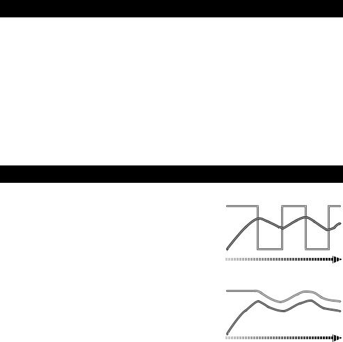
“THERMAL-THROTTLE” TEMPERATURE PROTECTION
Unlike “dragster” style amplifiers that put out lots of power for a few minutes, our Velocity series amps are engineered for full throttle, everyday driving. With our incredible Blaupunkt “Thermal Throttle”, our amps keep on playing without overheating, the common shut-down mode for most amplifiers.
All amplifiers heat up some over time. Using our moving voltage rail design, once warm, the rails pull back to prevent long term overheating thus preventing full shut off or even possible damage, as most other amps do. Once initiated this temporary system gain pullback lets you know you are really pushing the system hard but it’s not letting you down going into full shut down.
UNIQUE INSTALLATION FLEXIBILITY
Included in your amplifier kit is the very cool looking side rails and end caps. The side rail system allows you to butt amps side-by-side building a multi-channel monster of a system but with everything trimming out beautifully. An added benefit of the side rails and caps is the dressing down and hiding of all cables preventing any kind of snagged wires.
Conventional Amplifier Output
Audio Output
Temperature
Thermal Shut-Down |
Thermal Shut-Down |
Time
Blaupunkt ThermalThrottle™ Output
Audio Output
Temperature
Time
REMOTE GAIN CONTROL
You will find a very nice remote gain control for the amplifier. This gain control works only in the subwoofer mode (low-pass) providing about 20dB of gain range to dial in accurate bass levels or to simply pound out the tunes if desired.
NOISE ISOLATION MODE CONTROL
Inside the amplifier are isolation circuits to help prevent the intrusion of noise into the audio path. These circuits are turned on or off via the small switches visible through the bottom plate. Noise currents may enter the system via signal cables should there be small ground voltage differences. These are sometimes heard as a varying pitch with engine speed (alternator whine). The vehicle may also have a poor antenna ground, or overly sensitive AM radio tuner front end, which can result in low level back ground tones (birdies) in some parts of the AM radio band (550kHz-1710kHz).
Should either of these conditions occur, use a small screwdriver to slide the switch to the “ON” position and they should be eliminated. If no problems are detected, leave in the “OFF” position for maximum audio system performance.
– 3 –
www.midwestelectronics.com
SAFETY CONCERNS
We always recommend you have your Blaupunkt amplifiers professionally installed but the installation process is often so easy that the average consumer can achieve success with little trouble. Regardless of the person installing, you should be sure to review the following points before proceeding with the installation:
•READ THE MANUAL! Understanding the product and installation limitations before lifting a screwdriver.
•WEAR SAFETY GLASSES AT ALL TIMES - Flying debris are always dangerous.
•PROTECT THE VEHICLE - Always disconnect the negative battery cable before starting any kind of installation work. This prevents a possible high current electrical short (potential fires).
•HEAT - Keep all audio components away from nearby hot vehicle components that heat up over time such as hoses, high current wires, and braking system components.
•GIVE YOURSELF LOTS OF TIME - Rushing to complete an installation nearly always ends up with problems.
•DO NOT LISTEN AT HIGH SOUND LEVELS FOR A PROLONGED TIME - these amplifiers, used with high efficiency speakers from ANY manufacturer, have the potential to cause permanent hearing loss after listening at maximum volume levels for several hours.
English
INSTALLATION WARNINGS!
Before disassembling your beautiful new car you need some basic installation knowledge and skill with common hand and power tools. Following such basic installation tips and warnings will prevent possible damage to the vehicle and also prevent possible fires.
•AGAIN...READ THE MANUAL! There is a lot of helpful information in this manual that will save time and prevent problems later.
•COVER THE VEHICLE WORK AREAS - Use fender covers or blankets to protect the work areas from scratches or dings.
•DISCONNECT THE (-) LEAD ON THE BATTERY - No sparks or fires please!
•“REVIEW” THE INSTALLATION - Before using any tools or moving vehicle components, take five minutes to review the installation intentions (e.g., verify that an amplifier will fit in an area of a car before tearing out all the interior).
•“REVIEW” THE VEHICLE - Before drilling any holes or cutting into any surfaces, make sure there are no fuel or hydraulic lines behind the surfaces. Also make sure there are no wires routed directly behind or near the desired mounting area (remember...screws can often extend 1-2 inches behind the mounting surface).
•ENSURE PROPER FIT - Before cutting or drilling, make sure the amplifier will physically fit in its desired location. Check for clearance around rear deck torsion bars or other structural elements.
•EVERY CAR IS ASSEMBLED DIFFERENT - Every auto manufacturer uses different assembly techniques. Take care in removing/modifying all trim panels and mounting
surfaces since they often use unique screws or snap fasteners that are difficult to replace if they are lost or broken.
•BE CAREFUL WITH CABLE ROUTING - When routing audio cables, make sure RCA and speaker wires are routed away from high current power lines for audio amplifiers and vehicle systems lines when possible. This will help prevent noises from creeping into the audio system, plus prevent potential damage to the vehicle wiring itself.
•BE CAREFUL WITH ALL CONNECTIONS - When making connections, make sure each connection is clean and properly secured. Observe all polarity markings carefully to ensure proper end performance.
•CAUTION - FUEL TANKS AND FUEL LINES ARE NOW LOCATED DIRECTLY BENEATH THE REAR DECK IN MANY CARS - CHECK FOR ADEQUATE CLEARANCE BEFORE EVEN CONSIDERING SUCH A MOUNTING LOCATION!
– 4 –
www.midwestelectronics.com
 Loading...