

Page 1
Default Login Details
User’s Guide
NBG6615
AC1200 MU-MIMO Dual-Band Wireless Gigabit Router
Login URL http://192.168.212.1 (Router mode)
ht tp://192 .168.2.1 (AP mode)
User Name admin
Password 1234
Version 1.0 Edition 1, 06/2019
Copyright © 2019 Zyxel Communications Corporation
Page 2

IMPORTANT!
READ CAREFULLY BEFORE USE.
KEEP THIS GUIDE FOR FUTURE REFERENCE.
Screenshots and graphics in this book may differ slightly from what you see due to differences in release
versions or your computer operating system. Every effort has been made to ensure that the information
in this manual is accurate.
Related Documentation
•Quick Start Guide
The Quick Start Guide shows how to connect the NBG6615 and access the Web Configurator.
•More Information
Go to support.zyxel.com to find other information on the NBG6615
.
NBG6615’s User’s Guide
2
Page 3

Contents Overview
Contents Overview
User’s Guide ......................................................................................................................................10
Introduction ........................................................................................................................................... 11
The Web Configurator ......................................................................................................................... 16
Connection Wizard .............................................................................................................................. 20
Modes .................................................................................................................................................... 28
Tutorials .................................................................................................................................................. 39
Technical Reference ........................................................................................................................53
Wireless LAN .......................................................................................................................................... 54
WAN ....................................................................................................................................................... 67
LAN ......................................................................................................................................................... 77
DHCP Server .......................................................................................................................................... 81
Network Address Translation ............................................................................................................... 85
Dynamic DNS ........................................................................................................................................ 94
Static Route ........................................................................................................................................... 96
Firewall ................................................................................................................................................... 99
Content Filter ....................................................................................................................................... 104
Remote Management ....................................................................................................................... 106
Universal Plug-and-Play (UPnP) ......................................................................................................... 109
Bandwidth MGMT ............................................................................................................................... 117
System .................................................................................................................................................. 120
Logs ...................................................................................................................................................... 123
Tools ...................................................................................................................................................... 125
Sys OP Mode ....................................................................................................................................... 130
Language ............................................................................................................................................ 132
Troubleshooting and Appendices .................................................................................................133
Troubleshooting .................................................................................................................................. 134
NBG6615’s User’s Guide
3
Page 4

Table of Contents
Table of Contents
Contents Overview .............................................................................................................................3
Table of Contents.................................................................................................................................4
Part I: User’s Guide.......................................................................................... 10
Chapter 1
Introduction ........................................................................................................................................11
1.1 Overview ......................................................................................................................................... 11
1.2 Securing the NBG6615 ................................................................................................................... 12
1.3 LEDs .................................................................................................................................................. 13
1.4 The WPS Button ............................................................................................................................... 13
1.4.1 Using the WPS Button ............................................................................................................ 14
1.5 Reboot/Reset Button ...................................................................................................................... 14
1.6 Wall Mounting ................................................................................................................................. 14
Chapter 2
The Web Configurator........................................................................................................................16
2.1 Overview ......................................................................................................................................... 16
2.2 Accessing the Web Configurator ................................................................................................. 16
2.3 Resetting the NBG6615 .................................................................................................................. 18
Chapter 3
Connection Wizard............................................................................................................................20
3.1 Wizard Setup ................................................................................................................................... 20
3.1.1 Static IP Connection ............................................................................................................. 22
3.1.2 DHCP Client ........................................................................................................................... 22
3.1.3 PPPoE Connection ................................................................................................................ 23
3.1.4 PPTP Connection ................................................................................................................... 24
Chapter 4
Modes .................................................................................................................................................28
4.1 Overview ......................................................................................................................................... 28
4.2 Setting your NBG6615 to Router Mode ........................................................................................29
4.2.1 Status Screen (Router Mode) ..............................................................................................29
4.2.2 Router Mode Navigation Panel .......................................................................................... 33
4.3 Setting your NBG6615 to AP Mode ............................................................................................... 34
4.3.1 Status Screen (AP Mode) ..................................................................................................... 35
NBG6615’s User’s Guide
4
Page 5

Table of Contents
4.3.2 AP Navigation Panel ............................................................................................................. 37
Chapter 5
Tutorials...............................................................................................................................................39
5.1 Overview ......................................................................................................................................... 39
5.2 How to Connect to the Internet from an AP ............................................................................... 39
5.3 Configure Wireless Security Using WPS on both your NBG6615 and Wireless Client ............... 39
5.3.1 Push Button Configuration ................................................................................................... 40
5.3.2 PIN Configuration .................................................................................................................. 41
5.4 Enable and Configure Wireless Security without WPS on your NBG6615 ................................. 43
5.4.1 Configure Your Wireless Client ............................................................................................. 44
5.5 Using Multiple SSIDs on the NBG6615 ........................................................................................... 46
5.5.1 Configuring Security Settings of Multiple SSIDs .................................................................. 47
5.6 Installing UPnP in Windows 7 Example .......................................................................................... 50
5.7 Using Bandwidth Management on the NBG6615 ...................................................................... 50
Part II: Technical Reference........................................................................... 53
Chapter 6
Wireless LAN .......................................................................................................................................54
6.1 Overview ......................................................................................................................................... 54
6.2 What You Can Do .......................................................................................................................... 54
6.3 What You Should Know ................................................................................................................. 55
6.3.1 Wireless Security Overview ................................................................................................... 55
6.3.2 MBSSID .................................................................................................................................... 55
6.3.3 MAC Address Filter ................................................................................................................ 56
6.3.4 Encryption .............................................................................................................................. 56
6.3.5 WPS ......................................................................................................................................... 56
6.4 General Wireless LAN Screen ....................................................................................................... 57
6.4.1 No Security ............................................................................................................................. 58
6.4.2 WPA2-PSK or WPA-PSK/WPA2-PSK ....................................................................................... 58
6.5 MAC Filter ........................................................................................................................................ 59
6.6 Wireless LAN Advanced Screen ................................................................................................... 60
6.7 WPS Screen ..................................................................................................................................... 61
6.8 WPS Station Screen ........................................................................................................................ 63
6.9 Scheduling Screen ......................................................................................................................... 63
6.10 MBSSID Screen .............................................................................................................................. 64
Chapter 7
WAN ....................................................................................................................................................67
7.1 Overview ......................................................................................................................................... 67
NBG6615’s User’s Guide
5
Page 6

Table of Contents
7.2 What You Need To Know .............................................................................................................. 67
7.2.1 Configuring Your Internet Connection ............................................................................... 67
7.3 Internet Connection Screen .......................................................................................................... 68
7.3.1 Static IP ................................................................................................................................... 68
7.3.2 DHCP Client ........................................................................................................................... 70
7.3.3 PPPoE Connection ................................................................................................................ 71
7.3.4 PPTP Connection ................................................................................................................... 73
7.4 Advanced Screen .......................................................................................................................... 75
Chapter 8
LAN......................................................................................................................................................77
8.1 Overview ......................................................................................................................................... 77
8.2 What You Need To Know .............................................................................................................. 77
8.2.1 IP Address and Subnet Mask ...............................................................................................78
8.2.2 DNS Server Address Assignment .......................................................................................... 78
8.2.3 IP Pool Setup .......................................................................................................................... 79
8.2.4 LAN TCP/IP ............................................................................................................................. 79
8.3 LAN IP Screen .................................................................................................................................. 79
Chapter 9
DHCP Server........................................................................................................................................81
9.1 Overview ......................................................................................................................................... 81
9.2 What You Can Do .......................................................................................................................... 81
9.3 What You Need To Know .............................................................................................................. 81
9.4 General Screen ............................................................................................................................... 81
9.5 Static DHCP Screen ..................................................................................................................... 82
9.6 Client List Screen ............................................................................................................................. 83
Chapter 10
Network Address Translation ............................................................................................................85
10.1 Overview .................................................................................................................................... 85
10.2 What You Can Do ........................................................................................................................ 85
10.2.1 What You Need To Know ...................................................................................................86
10.3 General NAT Screen ..................................................................................................................... 87
10.4 NAT Application Screen ............................................................................................................. 88
10.5 Port Triggering Screen .................................................................................................................. 90
10.6 Technical Reference .................................................................................................................... 91
10.6.1 NAT Port Forwarding: Services and Port Numbers ........................................................... 92
10.6.2 NAT Port Forwarding Example ........................................................................................... 92
10.6.3 Trigger Port Forwarding ...................................................................................................... 92
10.6.4 Trigger Port Forwarding Example ...................................................................................... 93
10.6.5 Two Points To Remember About Trigger Ports ................................................................. 93
NBG6615’s User’s Guide
6
Page 7

Table of Contents
Chapter 11
Dynamic DNS .....................................................................................................................................94
11.1 Overview ...................................................................................................................................... 94
11.2 Dynamic DNS Screen ................................................................................................................. 94
Chapter 12
Static Route.........................................................................................................................................96
12.1 Overview .................................................................................................................................... 96
12.2 IP Static Route Screen ................................................................................................................. 96
Chapter 13
Firewall................................................................................................................................................99
13.1 Overview ..................................................................................................................................... 99
13.2 What You Can Do ........................................................................................................................ 99
13.3 What You Need To Know .......................................................................................................... 100
13.3.1 About the NBG6615 Firewall ............................................................................................ 100
13.3.2 VPN Pass Through Features .............................................................................................. 100
13.4 General Firewall Screen .......................................................................................................... 100
13.5 Services Screen ........................................................................................................................ 101
13.6 MAC Filter Screen ....................................................................................................................... 102
Chapter 14
Content Filter ....................................................................................................................................104
14.1 Overview ..................................................................................................................................... 104
14.2 What You Can Do ...................................................................................................................... 104
14.3 Filter Screen .............................................................................................................................. 104
Chapter 15
Remote Management.....................................................................................................................106
15.1 Overview ..................................................................................................................................... 106
15.1.1 Remote Management Limitations .................................................................................. 107
15.1.2 Remote Management and NAT ..................................................................................... 107
15.1.3 System Timeout .................................................................................................................. 107
15.2 WWW Screen ........................................................................................................................... 107
Chapter 16
Universal Plug-and-Play (UPnP)............................ ............................................ .... .... ......................109
16.1 Overview .................................................................................................................................... 109
16.2 What You Need to Know ........................................................................................................... 109
16.3 Configuring UPnP ........................................................................................................................ 110
16.4 Installing UPnP in Windows 7 Example ......................................................................................110
16.4.1 Using UPnP in Windows XP Example ................................................................................ 112
16.4.2 Web Configurator Easy Access ....................................................................................... 114
NBG6615’s User’s Guide
7
Page 8

Table of Contents
Chapter 17
Bandwidth MGMT.............................................................................................................................117
17.1 Overview ..................................................................................................................................... 117
17.2 What You Can Do ...................................................................................................................... 117
17.3 What You Need To Know .......................................................................................................... 117
17.4 Bandwidth MGMT Screen ......................................................................................................... 117
17.5 Advanced Screen ..................................................................................................................... 118
Chapter 18
System...............................................................................................................................................120
18.1 Overview ..................................................................................................................................... 120
18.2 What You Can Do ...................................................................................................................... 120
18.3 System General Screen ............................................................................................................ 120
18.4 Time Setting Screen .................................................................................................................... 121
Chapter 19
Logs...................................................................................................................................................123
19.1 Overview ..................................................................................................................................... 123
19.2 What You Need to Know ........................................................................................................... 123
19.3 View Log Screen ......................................................................................................................... 123
Chapter 20
Tools ..................................................................................................................................................125
20.1 Overview ..................................................................................................................................... 125
20.2 What You Can Do ...................................................................................................................... 125
20.3 Firmware Upload Screen ........................................................................................................... 125
20.4 Configuration Screen ................................................................................................................. 127
20.4.1 Backup Configuration ...................................................................................................... 127
20.4.2 Restore Configuration ...................................................................................................... 128
20.4.3 Back to Factory Defaults .................................................................................................. 128
20.5 Restart Screen ............................................................................................................................. 129
Chapter 21
Sys OP Mode ....................................................................................................................................130
21.1 Overview ..................................................................................................................................... 130
21.2 General Screen ........................................................................................................................... 130
Chapter 22
Language .........................................................................................................................................132
22.1 Language Screen ....................................................................................................................... 132
NBG6615’s User’s Guide
8
Page 9

Table of Contents
Part III: Troubleshooting and Appendices..................................................133
Chapter 23
Troubleshooting................................................................................................................................134
23.1 Power, Hardware Connections, and LEDs ............................................................................... 134
23.2 NBG6615 Access and Login ...................................................................................................... 135
23.3 Internet Access ........................................................................................................................... 136
23.4 Resetting the NBG6615 to Its Factory Defaults ........................................................................ 137
23.5 Wireless Problems ........................................................................................................................ 138
Appendix A IP Addresses and Subnetting.................................................................................... 139
Appendix B Pop-up Windows, JavaScripts and Java Permissions ............................................ 148
Appendix C Setting Up Your Computer’s IP Address.................................................................. 157
Appendix D Wireless LANs .............................................................................................................. 184
Appendix E Common Services ...................................................................................................... 197
Appendix F Legal Information ....................................................................................................... 200
Appendix G Customer Support..................................................................................................... 207
Index.................................................................................................................................................213
NBG6615’s User’s Guide
9
Page 10

PART I
User’s Guide
10
Page 11

1.1 Overview
WLAN
WAN
LAN1
LAN2
LAN3
LAN4
The NBG6615 extends the range of your existing wired network without additional wiring, providing easy
network access to mobile users.
You can create the following connections using the NBG6615:
• LAN. You can connect network devices via the Ethernet ports of the NBG6615 so that they can
communicate with each other and access the Internet.
• WLAN. Wireless clients can connect to the NBG6615 to access network resources.
• WAN. Connect to a broadband modem/router for Internet access.
Figure 1 NBG6615 Network
CHAPTER 1
Introduction
You can set up the NBG6615 with other IEEE 802.11b/g/n compatible devices in one of the following
device modes:
•Router
• Access Point
NBG6615’s User’s Guide
11
Page 12
Chapter 1 Introduction
Use a (supported) web browser to manage the NBG6615. Menus vary according to which mode you’re
using.
Router Mode AP Mode
See Chapter 4 on page 28 for more information on these modes.
1.2 Securing the NBG6615
Do the following things regularly to make the NBG6615 more secure and to manage the NBG6615 more
effectively.
• Change the password. Use a password that’s not easy to guess and that consists of different types of
characters, such as numbers and letters.
• Write down the password and put it in a safe place.
• Back up the configuration (and make sure you know how to restore it). Restoring an earlier working
configuration may be useful if the device becomes unstable or even crashes. If you forget your
password, you will have to reset the NBG6615 to its factory default settings. If you backed up an
earlier configuration file, you would not have to totally re-configure the NBG6615. You could simply
restore your last configuration.
NBG6615’s User’s Guide
12
Page 13
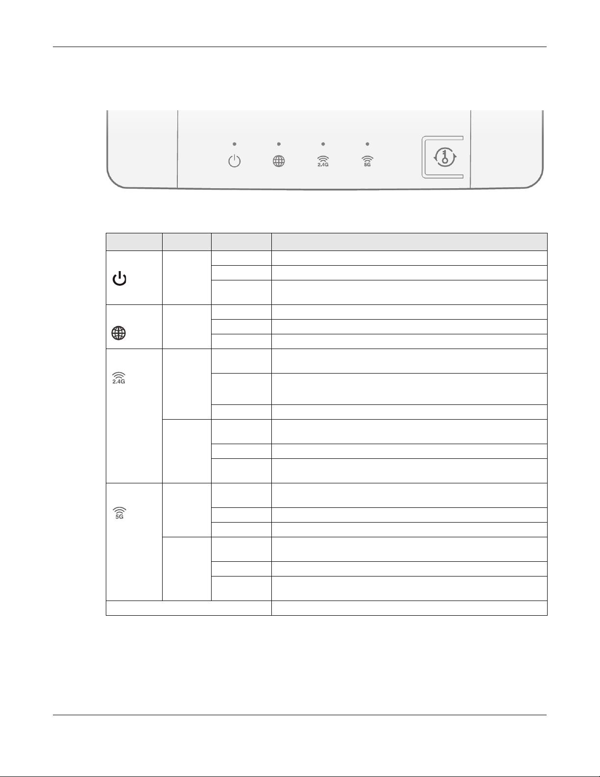
1.3 LEDs
Figure 2 Front Panel
The following table describes the LEDs and the WPS button.
Table 1 Front Panel LEDs and WPS Button
LED COLOR STATUS DESCRIPTION
POWER White On The NBG6615 is receiving power and functioning properly.
Internet White On An IP connection is available but there is no traffic.
WLAN_2.4G White On The NBG6615 is ready but is not sending/receiving data through the
Chapter 1 Introduction
Off The NBG6615 is not receiving power.
Blinking The NBG6615 is upgrading its firmware, restoring its configurations, or
rebooting its system.
Blinking The NBG6615 is sending/receiving data through the WAN.
Off An IP connection is not available.
wireless LAN.
Blinking The NBG6615 is sending/receiving data through the wireless LAN.
Amber Blinking The NBG6615 is negotiating a WPS connection with a wireless client via
WLAN_5G White On The NBG6615 is ready but is not sending/receiving data through the
Amber Blinking The NBG6615 is negotiating a WPS connection with a wireless client via
WPS Button Press to initiate the WPS process.
1.4 The WPS Button
Your NBG6615 supports WiFi Protected Setup (WPS), which is an easy way to set up a secure wireless
network. WPS is an industry standard specification, defined by the Wi-Fi Alliance.
Off The wireless LAN is not ready or has failed.
2.4G.
Off The WPS process is inactive.
Solid for 5
seconds
Blinking The NBG6615 is sending/receiving data through the wireless LAN.
Off The WPS status is not configured or disabled.
Off The WPS process is inactive.
Solid for 5
seconds
Successful WPS connection.
wireless LAN.
5G.
Successful WPS connection.
NBG6615’s User’s Guide
13
Page 14

WPS allows you to quickly set up a wireless network with strong security, without having to configure
security settings manually. Each WPS connection works between two devices. Both devices must
support WPS (check each device’s documentation to make sure).
Depending on the devices you have, you can either press a button (recommended) on the device
itself, or in its configuration utility or enter a PIN (a unique Personal Identification Number that allows one
device to authenticate the other) in each of the two devices. When WPS is activated on a device, it has
two minutes to find another device that also has WPS activated. Then, the two devices connect and set
up a secure network by themselves.
The WPS button is located at the front panel of the NBG6615.
1.4.1 Using the WPS Button
1 Make sure the power LED is on.
2 Press the WPS button within 3 seconds to turn on the WPS function
For more information on using WPS, see Section 5.3 on page 39.
Chapter 1 Introduction
1.5 Reboot/Reset Button
Your NBG6615 has a recessed reboot/reset button on its back panel. To reboot, press the button with a
paper clip or similar object for 3 to 5 seconds. To reset the NBG6615 to factory defaults, press for longer
than 10 seconds.
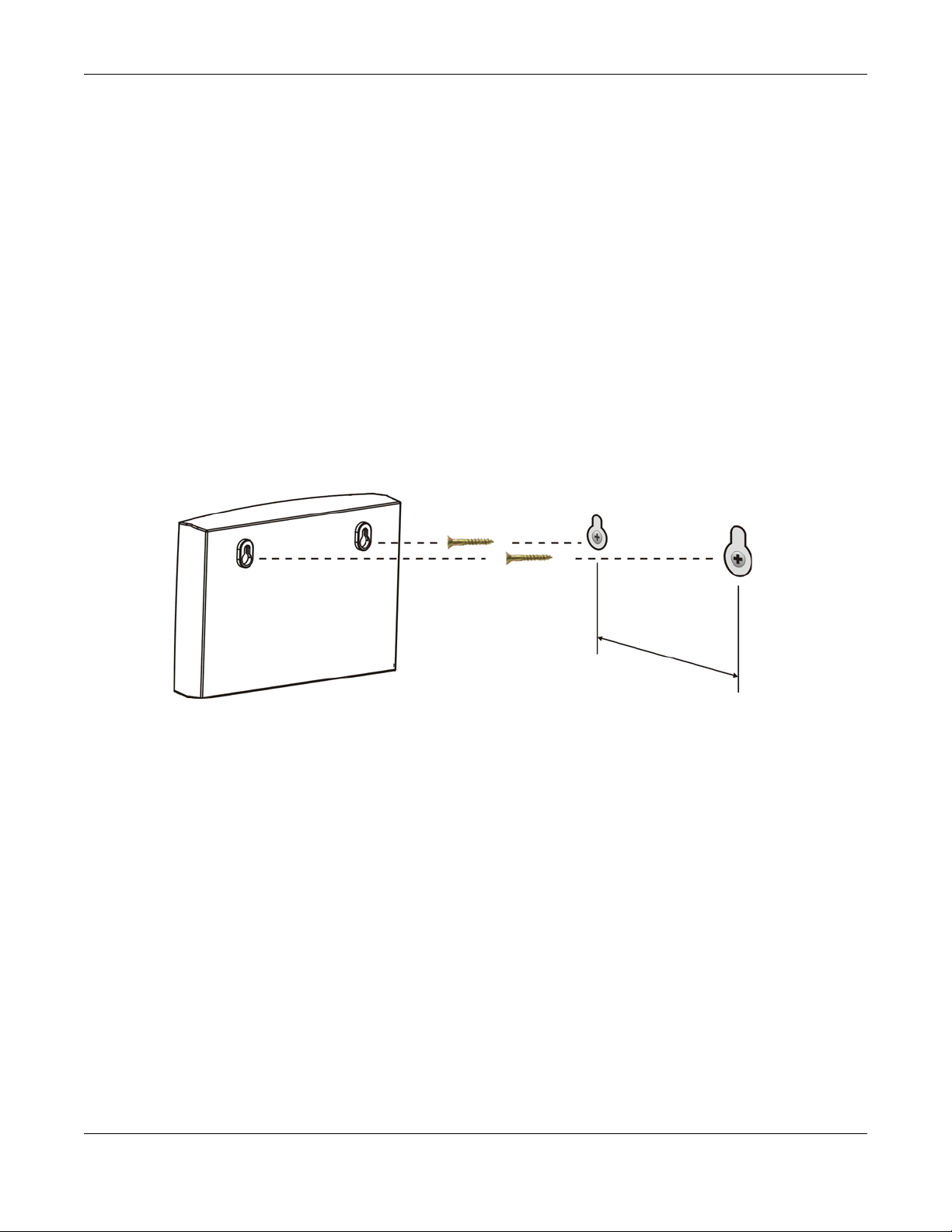
1.6 Wall Mounting
You may need screw anchors if mounting on a concrete or brick wall.
Table 2 Wall Mounting Information
Distance between holes 10.50 cm
M4 Screws Two
Screw anchors (optional) Two
Figure 3 Screw Specifications
NBG6615’s User’s Guide
14
Page 15
Chapter 1 Introduction
1 Select a position free of obstructions on a wall strong enough to hold the weight of the device.
2 Mark two holes on the wall at the appropriate distance apart for the screws.
Be careful to avoid damaging pipes or cables located inside the wall
when drilling holes for the screws.
3 If using screw anchors, drill two holes for the screw anchors into the wall. Push the anchors into the full
depth of the holes, then insert the screws into the anchors. Do not insert the screws all the way in - leave
a small gap of about 0.5 cm.
If not using screw anchors, use a screwdriver to insert the screws into the wall. Do not insert the screws all
the way in - leave a gap of about 0.5 cm.
4 Make sure the screws are fastened well enough to hold the weight of the NBG6615 with the connection
cables.
5 Align the holes on the back of the NBG6615 with the screws on the wall. Hang the NBG6615 on the
screws.
Figure 4 Wall Mounting Example
NBG6615’s User’s Guide
15
Page 16

2.1 Overview
This chapter describes how to access the NBG6615 Web Configurator and provides an overview of its
screens.
The Web Configurator is an HTML-based management interface that allows easy setup and
management of the NBG6615 via Internet browser. Use Internet Explorer 8.0 and later versions, Mozilla
Firefox, Google Chrome or Safari. The recommended screen resolution is 1366 by 768 pixels.
In order to use the Web Configurator you need to allow:
• Web browser pop-up windows from your device. Web pop-up blocking is enabled by default in
Windows XP SP (Service Pack) 2.
• JavaScript (enabled by default).
• Java permissions (enabled by default).
CHAPTER 2
The Web Configurator
Refer to Chapter 23 Troubleshooting to see how to make sure these functions are allowed in Internet
Explorer.
2.2 Accessing the Web Configurator
1 Make sure your NBG6615 hardware is properly connected and prepare your computer or computer
network to connect to the NBG6615 (refer to the Quick Start Guide).
2 Launch your web browser.
3 When the NBG6615 is in router mode, type "http://192.168.212.1" as the website address in your web
browser. 192.168.212.1 is the default LAN IP address in router mode (the default device mode). (The
default IP address in AP mode is 192.168.1.2).
Your computer must be in the same subnet in order to access this website address. In router mode, the
NBG6615 can assign your computer an IP address, so you must set your computer to get an IP address
automatically (computer factory default) or give it a fixed IP address in the range between
192.168.212.3 and 192.168.212.254 (see Appendix C on page 157).
4 Type admin (default) as the user name and 1234 (default) as the password and click OK.
NBG6615’s User’s Guide
16
Page 17
Chapter 2 The Web Configurator
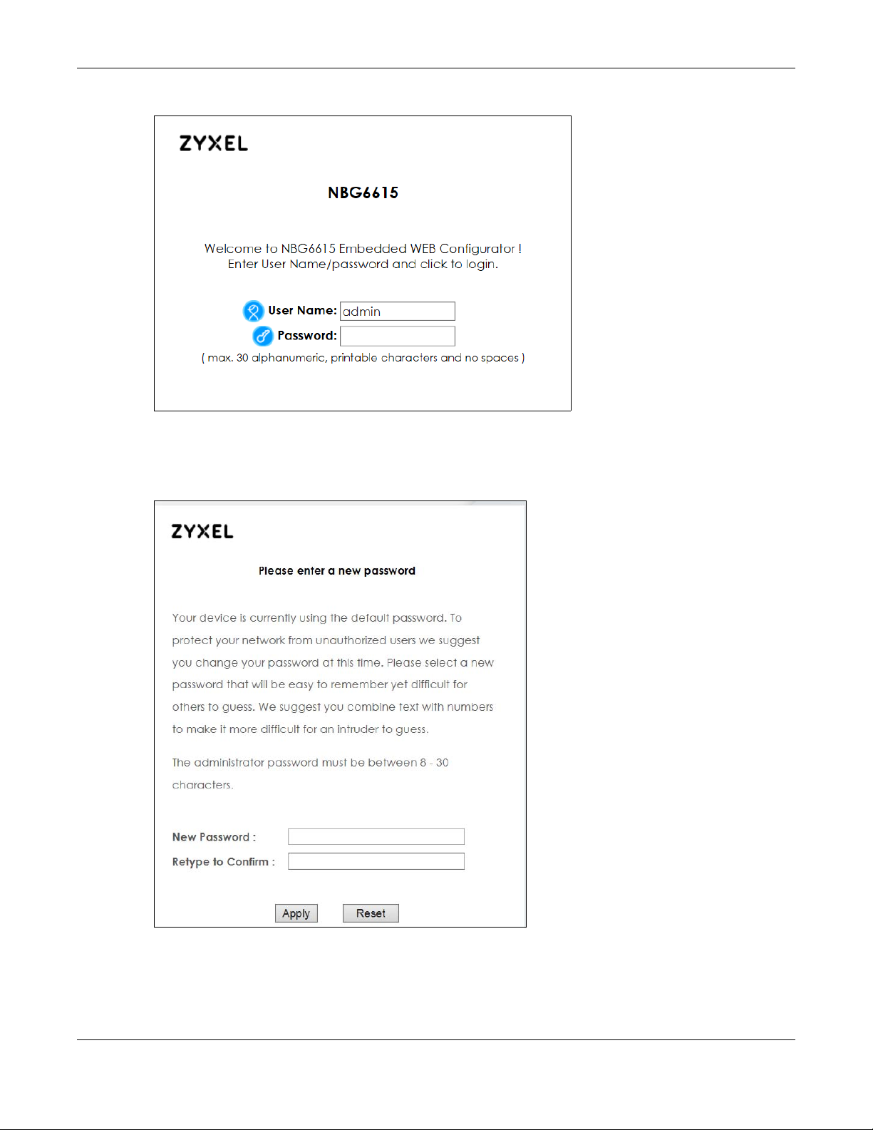
Figure 5 Login Screen
5 You should see a screen asking you to change your password (highly recommended) as shown next.
Type a new password. Click Apply to save your changes. Click Ignore if you do not want to change the
password this time.
Figure 6 Change Password Screen
Note: The management session automatically times out when the time period set in the
Administrator Inactivity Timer field expires (default five minutes). Simply log back into
the NBG6615 if this happens.
NBG6615’s User’s Guide
17
Page 18
Chapter 2 The Web Configurator
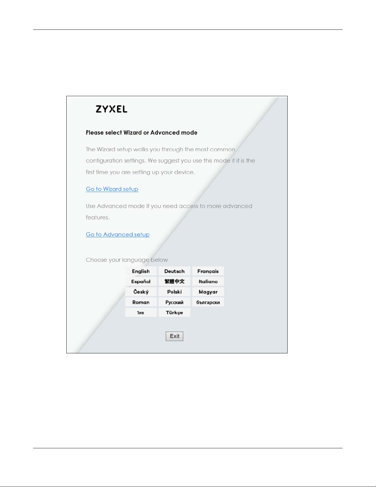
6 Select the setup type you want to use.
• Click Go to Wizard Setup to use the Configuration Wizard for basic Internet and Wireless setup.
• Click Go to Advanced Setup to view and configure all the NBG6615’s settings.
• Select a language to go to the basic Web Configurator in that language. To change to the
advanced configurator see Chapter 22 on page 132.
Figure 7 Selecting the setup mode
2.3 Resetting the NBG6615
If you forget your password or IP address, or you cannot access the Web Configurator, you will need to
use the Reset button at the back of the NBG6615 to reload the factory-default configuration file. This
means that you will lose all configurations that you had previously saved, the username will be reset to
admin and password will be reset to 1234. The IP address in router mode will be reset to “192.168.212.1”.
NBG6615’s User’s Guide
18
Page 19

Chapter 2 The Web Configurator
Make sure the power LED is on and press the Reset button for longer than 10 seconds to restart/reboot
and set the NBG6615 back to its factory-default configurations.
NBG6615’s User’s Guide
19
Page 20
3.1 Wizard Setup
This chapter provides information on the Wizard setup screens in the Web Configurator.
The Web Configurator’s Wizard setup helps you configure your device to access the Internet. Leave a
field blank if you don’t have that information.
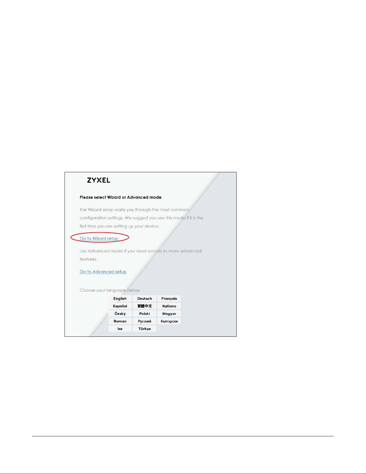
1 After you access the NBG6615 Web Configurator, click Go to Wizard setup.
CHAPTER 3
Connection Wizard
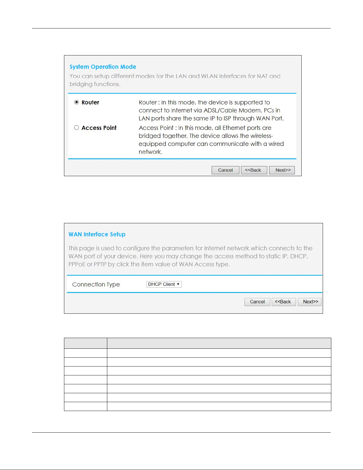
Use this screen to choose whether you want to use the NBG6615 as a router or an access point. Select
Router mode if you want the device to route traffic between a local network and another network such
NBG6615’s User’s Guide
20
Page 21
Chapter 3 Connection Wizard
as the Internet. Select Access Point if you want the device to bridge traffic between clients on the same
network. Click Next to save your settings.
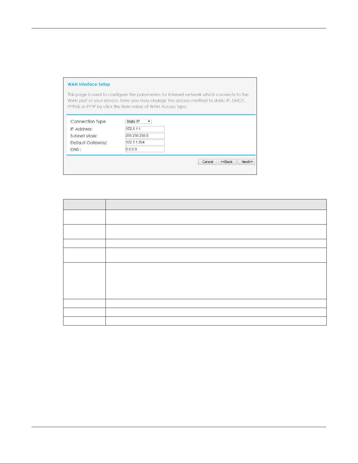
2 On the WAN Interface Setup screen, select an Internet access setting from the drop-down list. The
NBG6615 offers four Internet access settings: Static IP, Dynamic Host Configuration Protocol (DHCP
Client), PPP over Ethernet (PPPoE), and Point to Point Tunneling Protocol (PPTP). Check with your ISP to
make sure you use the correct setting. This Wizard screen varies according to the connection type that
you select.
The following table describes the labels on this screen.
Figure 8 WAN Interface Setup
LABEL DESCRIPTION
Static IP Select Static IP if your ISP assigned you a fixed IP address.
DHCP Client Select DHCP Client if your ISP did not assign you a fixed IP address.
PPPoE Select PPPoE for a dial-up connection.
PPTP Select PPTP to set up a virtual private network (VPN) in unsecured TCP/IP environments.
Cancel Click Cancel to exit the Wizard without saving.
Back Click Back to return to the previous screen.
Next Click Next to proceed to the next screen.
NBG6615’s User’s Guide
21
Page 22
3.1.1 Static IP Connection
The following Wizard screen allows you to assign a fixed IP address to the NBG6615.
Figure 9 Connection Type: Static IP
The following table describes the labels on this screen.
Chapter 3 Connection Wizard
Figure 10 Connection Type: Static IP
LABEL DESCRIPTION
Connection
Type
IP Address Select this option if you were given IP address and/or DNS server settings by the ISP. The fixed IP
Subnet Mask Enter the subnet mask address in this field.
Default
Gateway
DNS
Cancel Click Cancel to exit the Wizard without saving.
Back Click Back to return to the previous screen.
Next Click Next to proceed to the next screen.
3.1.2 DHCP Client
Select DHCP Client when your network administrator or ISP assigns your IP address dynamically. This is a
connection type often used with cable modems.
Select Static IP to give the NBG6615 a fixed, unique IP address.
address should be in the same subnet as your broadband modem or router.
Enter the gateway IP address provided by your ISP.
DNS (Domain Name System) is for mapping a domain name to its corresponding IP address and
vice versa. The DNS server is extremely important because without it, you must know the IP
address of a computer before you can access it. The NBG6615 uses a system DNS server (in the
order you specify here) to resolve domain names for DDNS and the time server. Enter the DNS
server’s IP address in this field.
NBG6615’s User’s Guide
22
Page 23
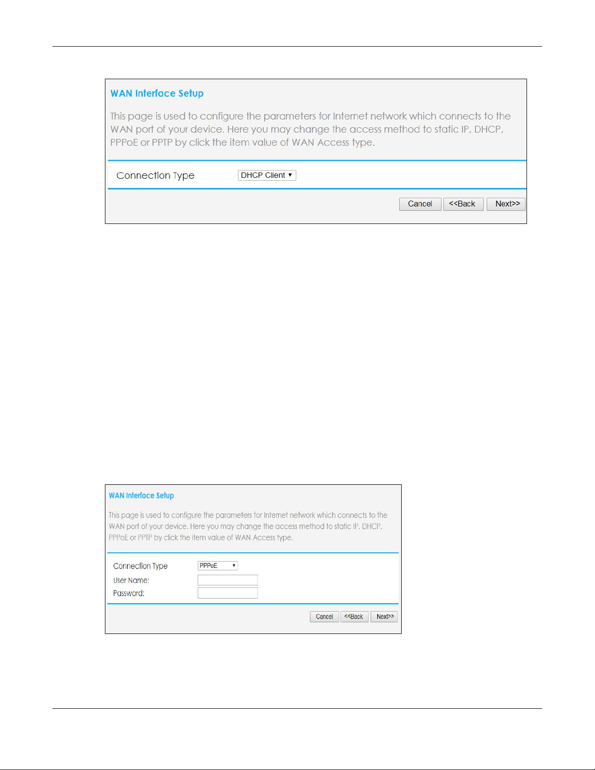
Figure 11 Connection Type: DHCP Client
3.1.3 PPPoE Connection
Point-to-Point Protocol over Ethernet (PPPoE) functions as a dial-up connection. PPPoE is an IETF (Internet
Engineering Task Force) standard specifying how a host personal computer interacts with a broadband
modem (for example DSL, cable, wireless, etc.) to achieve access to high-speed data networks.
For the service provider, PPPoE offers an access and authentication method that works with existing
access control systems (for instance, RADIUS).
Chapter 3 Connection Wizard
One of the benefits of PPPoE is the ability to let end users access one of multiple network services, a
function known as dynamic service selection. This enables the service provider to easily create and offer
new IP services for specific users.
Operationally, PPPoE saves significant effort for both the subscriber and the ISP/carrier, as it requires no
specific configuration of the broadband modem at the subscriber’s site.
By implementing PPPoE directly on the NBG6615 (rather than individual computers), the computers on
the LAN do not need PPPoE software installed, since the NBG6615 does that part of the task.
Furthermore, with NAT, all of the LAN's computers will have Internet access.
Figure 12 Connection Type: PPPoE
The following table describes the labels on this screen.
NBG6615’s User’s Guide
23
Page 24
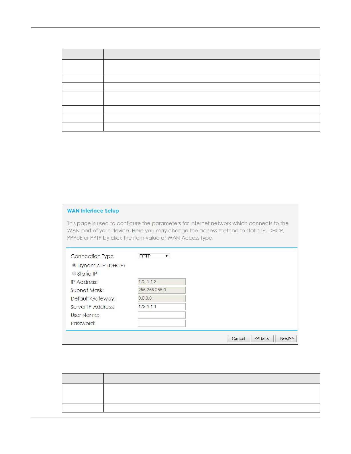
Table 3 Connection Type: PPPoE
LABEL DESCRIPTION
Connection
Type
User Name Type the user name given to you by your ISP.
Password Type the password associated with the user name above.
Confirm
Password
Cancel Click Cancel to exit the Wizard without saving.
Back Click Back to return to the previous screen.
Next Click Next to proceed to the next screen.
Select PPPoE for a dial-up connection.
Type the password again for confirmation.
3.1.4 PPTP Connection
Point-to-Point Tunneling Protocol (PPTP) is a network protocol that enables secure transfer of data from a
remote client to a private server, creating a Virtual Private Network (VPN) using TCP/IP-based networks.
PPTP supports on-demand, multi-protocol and virtual private networking over public networks, such as
the Internet.
Chapter 3 Connection Wizard
Figure 13 Connection Type: PPTP
The following table describes the labels on this screen.
Table 4 Connection Type: PPTP
LABEL DESCRIPTION
Connection
Type
IP Address If you selected Static IP, type the static IP address assigned to you by your ISP.
Select PPTP from the drop-down list box. Select Dynamic IP (DHCP) if your ISP dynamically assigns
DNS server information (and the NBG6615’s WAN IP address). Cick Static IP if you have the IP
address of a DNS server
NBG6615’s User’s Guide
24
Page 25
Chapter 3 Connection Wizard
LABEL DESCRIPTION
Subnet Mask If you selected Static IP, enter the subnet mask address assigned to you by your ISP (if given).
Default
Gateway
Server IP
Address
User Name Type the user name given to you by your ISP.
Password Type the password associated with the user name above.
Cancel Click Cancel to exit the Wizard without saving.
Back Click Back to return to the previous screen.
Next Click Next to proceed to the next screen.
If you selected Static IP, enter the gateway IP address of the PPTP server.
Type the IP address of the PPTP server.
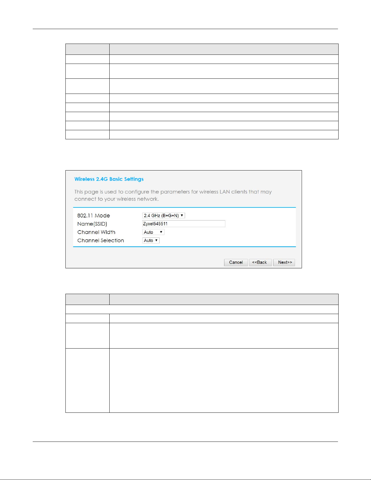
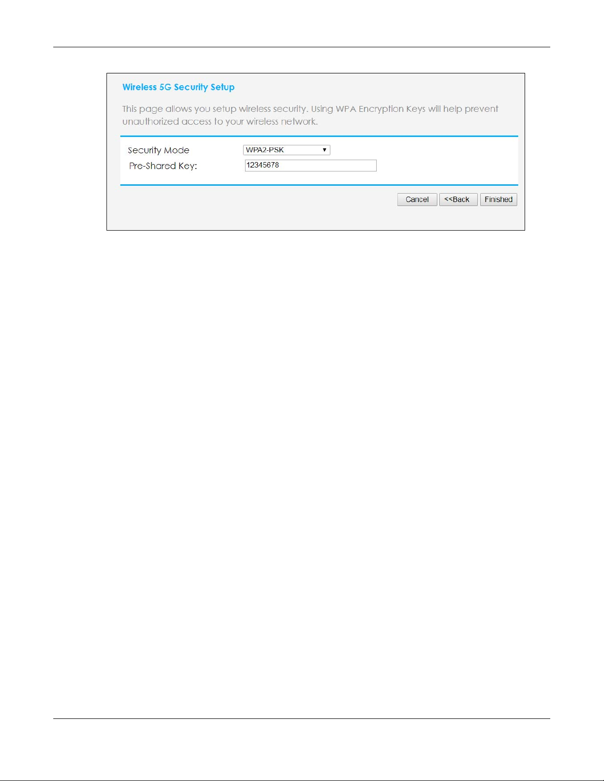
3 You can now set up the wireless LAN. Use this screen to configure the basic settings of the wireless 2.4G
band.
Figure 14 Wireless 2.4GSettings
The following table describes the labels on this screen.
Table 5 Wireless Settings
LABEL DESCRIPTION
Wireless 2.4G Basic Settings
802.11 Mode Select the IEEE 802.11 WLAN mode you wish to use on the NBG6615 from the drop-down list.
Name (SSID) Enter a descriptive name (up to 32 printable 7-bit ASCII characters) for the wireless LAN.
If you change this field on the NBG6615, make sure all wireless stations use the same SSID in order
to access the network.
Channel Width Select whether the NBG6615 uses a wireless channel width of 20MHz, 40MHz, or 80 MHz
(available with 5G only). Select Auto to allow the NBG6615 to adjust the channel bandwidth
depending on network conditions.
Select 20 MHz if you want to lessen radio interference with other wireless devices in your
neighborhood or the wireless clients do not support channel bonding.
Select 40 MHz if your 2.4G to bond two adjacent radio channels to increase throughput. The
wireless clients must also support 40 MHz.
Select 80MHz (available for 5G only) if you have a network with only a few wireless clients.
NBG6615’s User’s Guide
25
Page 26
Chapter 3 Connection Wizard
Table 5 Wireless Settings
LABEL DESCRIPTION
Channel
Selection
Cancel Click Cancel to close the Wizard screen without saving.
Back Click Back to display the previous screen.
Next Click Next to proceed to the next screen.
The range of radio frequencies used by IEEE 802.11b/g/n wireless devices is called a channel.
Set the operating frequency/channel depending on your particular region. Select a channel
from the drop-down list box. The options vary depending on the frequency band and the
country you are in.
Select Auto to have the NBG6615 automatically choose the channel with the least interference.
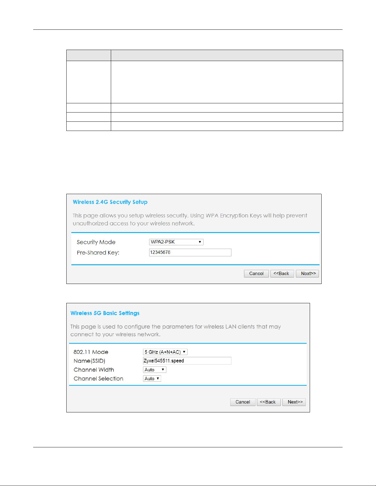
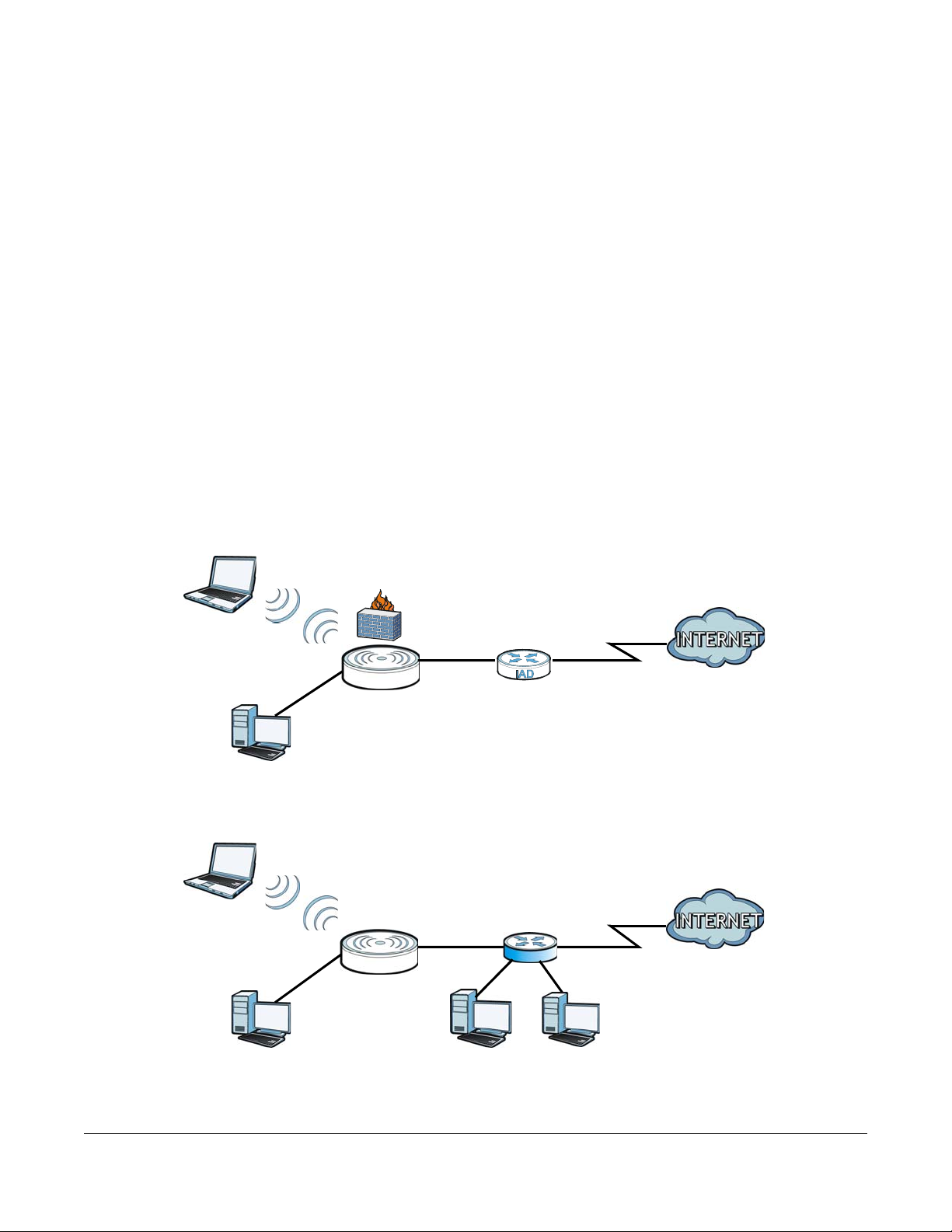
4 Next, select whether you want to use encryption to protect the information sent through the wireless
network. In the drop-down list, you can choose None, WPA2-PSK, and WPA-PSK/WPA2-PSK. WPA2-PSK is
currently the strongest form of security and is recommended for all uses. If you have older devices that
don't support WPA2-PSK, select WPA-PSK/WPA2-PSK, which allows newer devices to use WPA2-PSK and
legacy devices to use WPA-PSK. If you select an encryption protocol, create a password in the Pre-
shared Key field. The password can be 8 to 63 case-sensitive ASCII characters (including spaces and
symbols) or 64 hexadecimal characters (“0-9,” “A-F”). Click Next to save the settings.
5 Repeat steps 4 and 5 to set up the wireless 5G.
NBG6615’s User’s Guide
26
Page 27
Chapter 3 Connection Wizard
6 Click Finished to complete the Wizard setup.
Well done! You have successfully set up your NBG6615 to operate on your network and access the
Internet.
NBG6615’s User’s Guide
27
Page 28
4.1 Overview
LEW
WLAN
LAN
WAN
N
IAD
LEW
WLAN
LAN
WAN
N
R
You can set up the NBG6615 with other IEEE 802.11b/g/n compatible devices in different device modes.
Note: Choose your device mode carefully to avoid having to change it later. The NBG6615
automatically restarts when you change modes.
The default LAN IP address of the NBG6615 in Router mode is 192.168.212.1. The default
IP address of the NBG6615 in Access Point mode is 192.168.1.2.
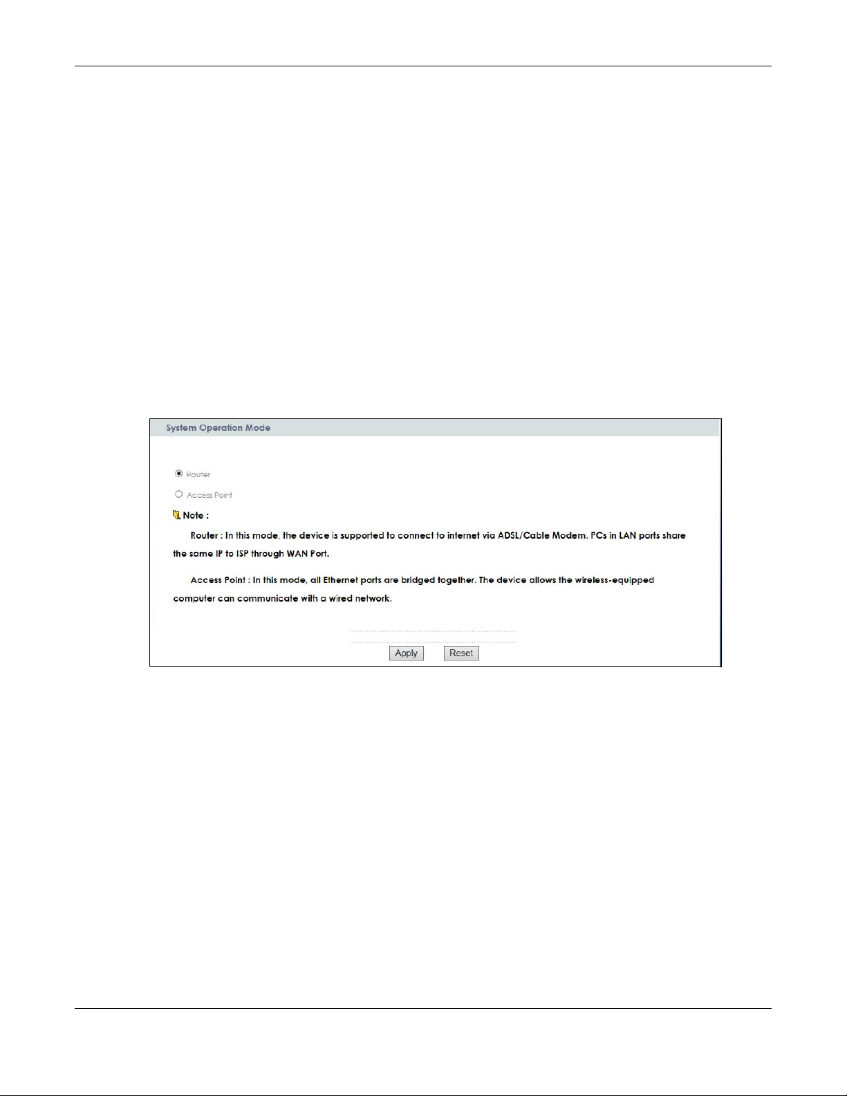
• Router: Use this mode if you want to use routing functions such as LAN DHCP, NAT, firewall and so on,
on the NBG6615 (N). The NBG6615 has separate LAN and WAN network IP addresses. Connect the
WAN port to an Internet Access Device (IAD) such as a broadband modem.
Figure 15 Router
CHAPTER 4
Modes
• Access Point: Use this mode if you already have a Router (R) in your network and you want to set up a
wireless network and bridge the wired and wireless connections on the NBG6615.
Figure 16 AP Mode
NBG6615’s User’s Guide
28
Page 29
Chapter 4 Modes
4.2 Setting your NBG6615 to Router Mode
The NBG6615 is set to wireless router mode by default. If it was changed and now you want to set it
back, do the following procedure.
1 Connect your computer to the LAN port of the NBG6615.
2 The default LAN IP address of the NBG6615 is 192.168.212.1 in router mode and 192.168.1.2 by default in
Access Point mode. In router mode, the NBG6615 can assign your computer an IP address, so you must
set your computer to get an IP address automatically (computer factory default) or give it a fixed IP
address in the range between 192.168.212.3 and 192.168.212.254.
3 After you’ve set your computer’s IP address, open a web browser such as Internet Explorer and type the
IP address of the NBG6615 as the web address in your web browser.
4 Log into the Web Configurator. See the Chapter 2 on page 16 for instructions on how to do this.
5 Go to Maintenance > Sys OP Mode > General and select Router.
6 Click Apply.
Note: Wait while the NBG6615 restarts, then log in to the Web Configurator again. The
NBG6615 IP address is now 192.168.212.1.
4.2.1 Status Screen (Router Mode)
The screen below shows the status screen in Router mode.
NBG6615’s User’s Guide
29
Page 30

Chapter 4 Modes
Figure 17 Status Screen (Router Mode)
The following table describes the icons shown in the Status screen.
Table 6 Status Screen Icon Key
ICON DESCRIPTION
Click this icon to open the setup wizard.
Click this icon to view copyright and a link for related product information.
Click this icon at any time to exit the Web Configurator.
The following table describes the labels shown in the Status screen in Router mode.
Table 7 Web Configurator Status Screen (Router Mode)
LABEL DESCRIPTION
Device Information
System Name This is the System Name you enter in the Maintenance > System > General screen.
It is for identification purposes.
Firmware Version This is the current firmware version of the NBG6615.
WAN Information
- MAC Address This shows the WAN Ethernet adapter MAC Address of your device.
- Connection Type This shows the current connection type.
- IP Address This shows the WAN port’s IP address.
- IP Subnet Mask This shows the WAN port’s subnet mask.
- Gateway This shows the WAN port’s gateway IP address.
NBG6615’s User’s Guide
30
Page 31

Chapter 4 Modes
Table 7 Web Configurator Status Screen (Router Mode) (continued)
LABEL DESCRIPTION
- DNS This shows the IP address of your DNS server.
LAN Information
- MAC Address This shows the LAN Ethernet adapter MAC Address of your device.
- IP Address This shows the LAN port’s IP address.
- IP Subnet Mask This shows the LAN port’s subnet mask.
- DHCP Server This shows the LAN port’s DHCP server status.
WLAN Information (5.G/2.4G)
- MAC Address This shows the wireless adapter MAC Address of your device.
- Status This shows the current status of the Wireless LAN - On, Off or Off by scheduler.
- Name (SSID) This shows a descriptive name used to identify the NBG6615 in the wireless LAN.
- Channel This shows the channel number which you select manually or the NBG6615
automatically scans and selects.
- Operating Channel This shows the channel number which the NBG6615 is currently using over the
wireless LAN.
- Security Mode This shows the level of wireless security the NBG6615 is using.
- 802.11 Mode This shows the wireless standard.
- WPS This displays Configured when the WPS has been set up.
This displays Unconfigured if the WPS has not been set up.
System Status
Operation Mode This field shows the device operation mode: Router, or Access Point.
System Up Time This is the total time the NBG6615 has been on.
Current Date/Time This field displays your NBG6615’s present date and time.
System Setting
- Firewall This shows whether the firewall is active or not.
- UPnP This shows whether UPnP is active or not.
Interface
-Lan 1 This shows the first LAN port’s connection status and operating speed.
-Lan 2 This shows the second LAN port’s connection status and operating speed.
-Lan 3 This shows the third LAN port’s connection status and operating speed.
-Lan 4 This shows the fourth LAN port’s connection status and operating speed.
Summary
Client Table Use this screen to view current client information. Click “Details...” to see the
Packet Statistics Use this screen to view port status and packet specific statistics. Click “Details...” to
4.2.1.1 Summary: Client Table
Click the status to display Network > Wireless LAN > WPS screen.
screen.
see the screen.
Click the Client Table (Details...) hyperlink on the Status screen. The client table shows current client
information (including Host Name, IP Address, and MAC Address) of all network clients connected to
the NBG6615.
NBG6615’s User’s Guide
31
Page 32

Chapter 4 Modes
Figure 18 Summary: Client Table
The following table describes the labels in this screen.
Table 8 Summary: Client Table
LABEL DESCRIPTION
# This is the index number of the host computer.
Host Name This field displays the computer host name.
IP Address This field displays the IPv4 address relative to the # field listed above.
MAC Address This field shows the MAC address of the computer with the name in the Host Name field.
Every Ethernet device has a unique MAC (Media Access Control) address, which uniquely
identifies a device. The MAC address is assigned at the factory and consists of six pairs of
hexadecimal characters, for example 00:A0:C5:00:00:02.
Interface This field shows the NBG6615’s interface to which the client is connected.
4.2.1.2 Summary: Packet Statistics
Click the Packet Statistics (Details...) hyperlink on the Status screen. Read-only information here includes
the number of packets sent and received on each port. The Click the Refresh button to update
statistics.
Figure 19 Summary: Packet Statistics
NBG6615’s User’s Guide
32
Page 33

Chapter 4 Modes
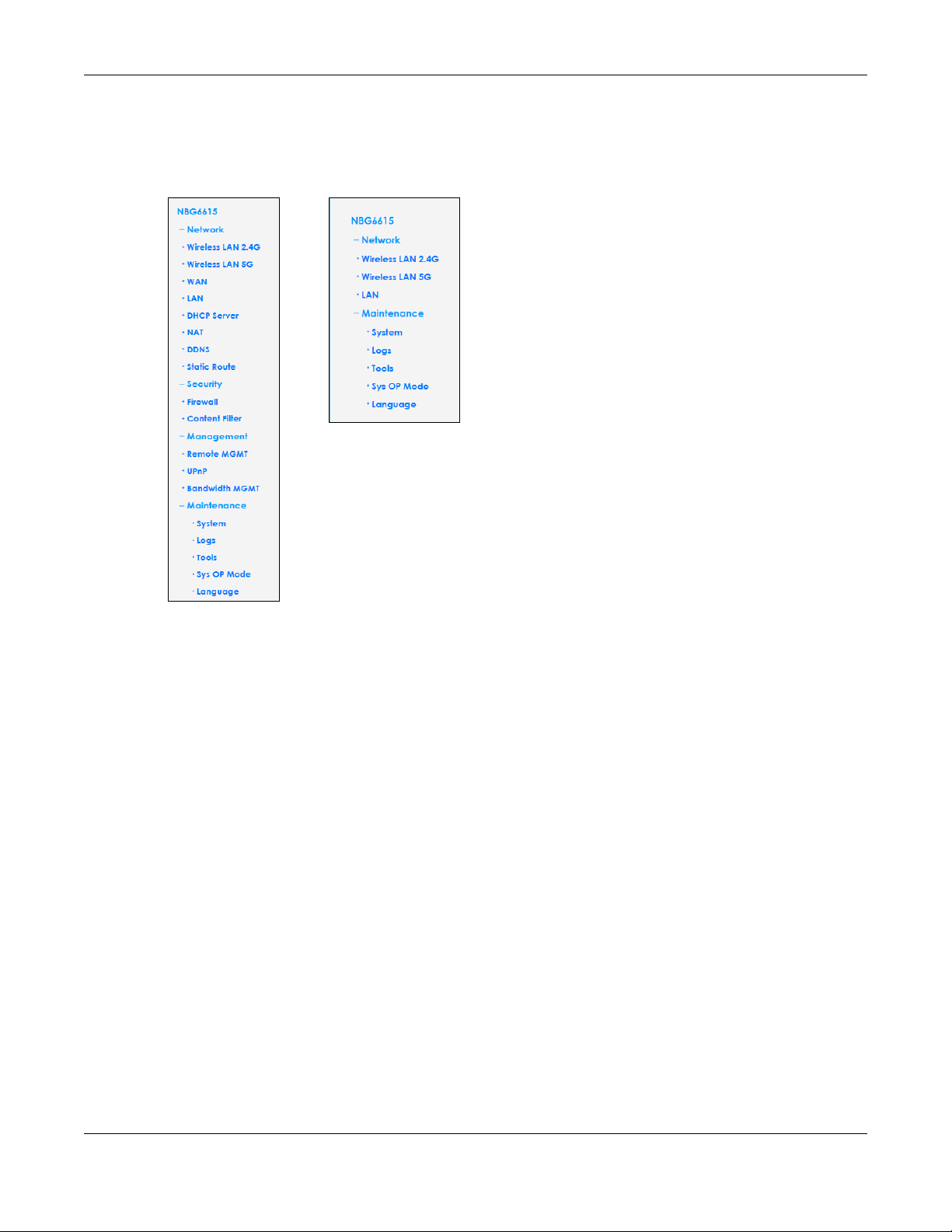
4.2.2 Router Mode Navigation Panel
Use the menu in the navigation panel menus to configure NBG6615 features in Router Mode.
Figure 20 Menus: Router Mode
The following table describes the sub-menus.
Table 9 Menus: Router Mode
LINK TAB FUNCTION
Network
Wireless
LAN (2.4G/
5G)
WAN Internet
LAN IP Use this screen to configure LAN IPv4 address and subnet mask.
General Use this screen to configure wireless LAN.
MAC Filter Use the MAC filter screen to configure the NBG6615 to block access to devices
or block the devices from accessing the NBG6615.
WLAN
Advanced
Setup
WPS Use this screen to configure WPS.
WPS Station Use this screen to add a wireless station using WPS.
Scheduling Use this screen to schedule the times the Wireless LAN is enabled.
MBSSID Use this screen to configure multiple SSIDs on the NBG6615.
Connection
Advanced Use this screen to configure multicast WAN and auto IP setup.
This screen allows you to configure advanced wireless settings.
This screen allows you to configure ISP parameters, WAN IP address
assignment, DNS servers and the WAN MAC address.
NBG6615’s User’s Guide
33
Page 34

Chapter 4 Modes
Table 9 Menus: Router Mode (continued)
LINK TAB FUNCTION
DHCP
Server
NAT General Use this screen to enable NAT.
DDNS General Use this screen to configure Dynamic DNS, a service that allows you to map a
Static Route IP Static Route Use this screen to configure IP static routes.
Security
Firewall General Use this screen to activate/deactivate the firewall.
Content
Filter
Management
Remote
MGMT
UPnP UPnP Use this screen to enable UPnP on the NBG6615.
Bandwidth
MGMT
Maintenance
System General Use this screen to view and change administrative settings such as system and
Logs View Log Use this screen to view the logs for the categories that you selected.
Tools Firmware Use this screen to upload firmware to your NBG6615.
Sys OP
Mode
Language Language This screen allows you to select the language you prefer.
General Use this screen to enable the NBG6615’s DHCP server.
Static DHCP Use this screen to assign IP addresses to specific individual computers based
on their MAC addresses and to have DNS servers assigned by the DHCP server.
Client List Use this screen to view current DHCP client information and to always assign
an IP address to a MAC address (and host name).
Application Use this screen to configure servers behind the NBG6615.
Port Triggering Use this screen to configure port triggering settings on the NBG6615.
fixed domain name to a non-fixed IP address.
Services Use this screen to enable or disable ICMP and VPN passthrough features.
MAC Filter Use this screen to whitelist or blacklist devices based on their MAC address.
Filter Use this screen to configure content filter settings on the NBG6615.
WWW Use this screen to configure through which interface(s) and from which IP
address(es) users can use HTTP to manage the NBG6615.
General Use this screen to enable bandwidth management on the NBG6615.
Advanced Use this screen to set the upstream bandwidth and edit a bandwidth
management rule.
domain names, password and inactivity timer.
Time Setting Use this screen to change your NBG6615’s time and date.
Configuration Use this screen to backup and restore the configuration or reset the factory
defaults to your NBG6615.
Restart This screen allows you to reboot the NBG6615 without turning the power off.
General This screen allows you to select the device operating mode.
4.3 Setting your NBG6615 to AP Mode
1 Connect your computer to the LAN port of the NBG6615.
2 The default LAN IP address of the NBG6615 is 192.168.212.1 in router mode and 192.168.1.2 in Access
Point mode.
NBG6615’s User’s Guide
34
Page 35

Chapter 4 Modes
3 After you’ve set your computer’s IP address, open a web browser such as Internet Explorer and type the
IP address of the NBG6615 as the web address in your web browser.
4 Log into the Web Configurator. See the Chapter 2 on page 16 for instructions on how to do this.
5 Go to Maintenance > Sys OP Mode > General and select Access Point.
6 Click Apply. Your NBG6615 is now in AP Mode.
Note: Wait while the NBG6615 restarts, then log in to the Web Configurator again.
4.3.1 Status Screen (AP Mode)
Click on Status. The screen below shows the status screen in AP Mode.
NBG6615’s User’s Guide
35
Page 36

Figure 21 Status Screen (AP Mode)
Chapter 4 Modes
The following table describes the labels shown on the Status screen.
Table 10 Status Screen (AP Mode)
LABEL DESCRIPTION
Device Information
System Name This is the System Name you enter in the Maintenance > System > General screen. It is for
identification purposes.
Firmware Version This is the current firmware version of the NBG6615.
WAN Information
-MAC Address This shows the WAN Ethernet adapter MAC Address of your device.
-Connection Type This shows the current connection type.
-IP Address This shows the WAN port’s IP address.
-IP Subnet Mask This shows the WAN port’s subnet mask.
-Gateway This shows the WAN port’s gateway IP address.
-DNS This shows the IP address of your DNS server.
LAN Information
- MAC Address This shows the LAN Ethernet adapter MAC Address of your device.
- IP Address This shows the LAN port’s IP address.
- IP Subnet Mask This shows the LAN port’s subnet mask.
- DHCP Server This shows the LAN port’s DHCP server status.
WLAN Information (5g/2.4G)
- MAC Address This shows the wireless adapter MAC Address of your device.
NBG6615’s User’s Guide
36
Page 37

Chapter 4 Modes
Table 10 Status Screen (AP Mode) (continued)
LABEL DESCRIPTION
- Status This shows the current status of the Wireless LAN - On, Off, or Off by scheduler.
- Name (SSID) This shows a descriptive name used to identify the NBG6615 in the wireless LAN.
- Channel This shows the channel number, which you select manually or the NBG6615
automatically scans and selects.
- Operating Channel This shows the channel number which the NBG6615 is currently using over the wireless
LAN.
- Security Mode This shows the level of wireless security the NBG6615 is using.
- 802.11 Mode This shows the IEEE 802.11 standard that the NBG6615 supports. Wireless clients must
- WPS This shows the WPS (WiFi Protected Setup) Status. Click the status to display Network >
System Status
Operation Mode This field shows the device operating mode: Router, or Access Point.
System Up Time This is the total time the NBG6615 has been on.
Current Date/Time This field displays your NBG6615’s present date and time.
Summary
Client Table Use this screen to view current client information. Click “Details...” to see the screen.
Packet Statistics Use this screen to view port status and packet specific statistics. Click “Details...” to see
support the same standard in order to be able to connect to the NBG6615
Wireless LAN > WPS screen.
the screen.
4.3.2 AP Navigation Panel
Use the menu in the navigation panel to configure NBG6615 features in AP Mode.
The following screen and table show the features you can configure in AP Mode.
Figure 22 Menu: AP Mode
NBG6615’s User’s Guide
37
Page 38

Chapter 4 Modes
The following table describes the sub-menus.
Table 11 Menu: AP Mode
LINK TAB FUNCTION
Network
Wireless LAN
(2.4G/5G)
LAN IP Use this screen to configure LAN IP address and subnet mask.
Maintenance
System General Use this screen to view and change administrative settings such as system
Logs View Log Use this screen to view the logs for the categories that you selected.
Tools Firmware Use this screen to upload firmware to your NBG6615.
Sys OP Mode General This screen allows you to select the device operating mode: Router and
Language Language This screen allows you to select the language you prefer.
General Use this screen to configure wireless LAN.
MAC Filter Use the MAC filter screen to configure the NBG6615 to block access to
WLAN
Advanced
Setup
WPS Use this screen to configure WPS.
WPS Station Use this screen to add a wireless station using WPS.
Scheduling Use this screen to schedule the times the Wireless LAN is enabled.
MBSSID Use this screen to configure multiple SSIDs on the NBG6615.
Time Setting Use this screen to change your NBG6615’s time and date.
Configuration Use this screen to backup and restore the configuration or reset the factory
Restart This screen allows you to reboot the NBG6615 without turning the power off.
devices or block the devices from accessing the NBG6615.
This screen allows you to configure advanced wireless settings.
and domain names, password and inactivity timer.
defaults to your NBG6615.
Access Point.
NBG6615’s User’s Guide
38
Page 39

CHAPTER 5
AP
B
Tutorials
5.1 Overview
This chapter provides tutorials for your NBG6615 as follows:
• How to Connect to the Internet from an AP
• Configure Wireless Security Using WPS on both your NBG6615 and Wireless Client
• Enable and Configure Wireless Security without WPS on your NBG6615
• Using Multiple SSIDs on the NBG6615
• Using Bandwidth Management on the NBG6615
5.2 How to Connect to the Internet from an AP
This section gives you an example of how to set up an access point (AP) and wireless client (a notebook,
B in this example) for wireless communication. B can access the Internet through the AP wirelessly.
Figure 23 Wireless AP Connection to the Internet
5.3 Configure Wireless Security Using WPS on both your NBG6615 and Wireless Client
This section gives you an example of how to set up wireless network using WPS. This example uses the
NBG6615 as the AP and NWD210N as the wireless client that connects to a notebook.
Note: The wireless client must be a WPS-aware device (for example, a WPS USB adapter or
PCI card).
There are two WPS methods for creating a secure connection. This tutorial shows you how to do both.
• Push Button Configuration (PBC) - create a secure wireless network simply by pressing a button. See
Section 5.3.1 on page 40. This is the easier method.
NBG6615’s User’s Guide
39
Page 40

• PIN Configuration - create a secure wireless network simply by entering a wireless client's PIN (Personal
Identification Number) in the NBG6615’s interface. See Section 5.3.2 on page 41. This is the more
secure method, since one device can authenticate the other.
5.3.1 Push Button Configuration
1 Make sure that your NBG6615 is turned on and that it is within range of your computer.
2 Make sure that you have installed the wireless client (this example uses the NWD210N) driver and utility in
your notebook.
3 In the wireless client utility, find the WPS settings. Enable WPS and press the WPS button (Start or WPS
button)
4 Log into NBG6615’s Web Configurator and press Push Button in the Network > Wireless LAN (2.4G/5G)>
WPS Station screen.
Note: Your NBG6615 has a WPS button located on its front panel, as well as a WPS button in its
configuration utility. Both buttons have exactly the same function; you can use one or
the other.
Chapter 5 Tutorials
Note: It doesn’t matter which button is pressed first. You must press the second button within
two minutes of pressing the first one.
The NBG6615 sends the proper configuration settings to the wireless client. This may take up to two
minutes. Then the wireless client is able to communicate with the NBG6615 securely.
The following figure shows you an example to set up wireless network and security by pressing a button
on both NBG6615 and wireless client (the NWD210N in this example).
NBG6615’s User’s Guide
40
Page 41

Chapter 5 Tutorials
Wireless Client
NBG6615
SECURITY INFO
COMMUNICATION
WITHIN 2 MINUTES
WPS/Reset
Figure 24 Example WPS Process: Push Button Configuration Method
5.3.2 PIN Configuration
When you use the PIN configuration method, you need to use both NBG6615’s configuration interface
and the client’s utilities.
1 Launch your wireless client’s configuration utility. Go to the WPS settings and select the PIN method to
get a PIN number.
2 Enter the PIN number to the PIN field in the Network > Wireless LAN (2.4G/5G)> WPS Station screen on the
NBG6615.
3 Click the Start buttons (or button next to the PIN field) on both the wireless client utility screen and the
NBG6615’s WPS Station screen within two minutes.
The NBG6615 authenticates the wireless client and sends the proper configuration settings to the wireless
client. This may take up to two minutes. Then the wireless client is able to communicate with the
NBG6615 securely.
The following figure shows you the example to set up wireless network and security on NBG6615 and
wireless client (ex. NWD210N in this example) by using PIN method.
NBG6615’s User’s Guide
41
Page 42

Chapter 5 Tutorials
Authentication by PIN
SECURITY INFO
WITHIN 2 MINUTES
Wireless Client
NBG6615
COMMUNICATION
Figure 25 Example WPS Process: PIN Method
NBG6615’s User’s Guide
42
Page 43

Chapter 5 Tutorials
5.4 Enable and Configure Wireless Security without WPS on your NBG6615
This example shows you how to configure wireless security settings with the following parameters on your
NBG6615.
SSID SSID_Example3
Channel 6
Security WPA-PSK/WPA2-PSK
(Pre-Shared Key: ThisismyWPA-PSKpre-sharedkey)
Follow the steps below to configure the wireless settings on your NBG6615.
The instructions require that your hardware is connected (see the Quick Start Guide) and you are
logged into the Web Configurator through your LAN connection (see Section 2.2 on page 16).
1 Open the Wireless LAN > General screen in the NBG6615’s Web Configurator.
2 Make sure the Enable Wireless LAN check box is selected.
3 Enter SSID_Example3 as the SSID and select a channel.
4 Set security mode to WPA-PSK/WPA2-PSK and enter ThisismyWPA-PSKpre-sharedkey in the Pre-Shared
Key field. Click Apply.
Figure 26 Tutorial: Network > Wireless LAN 2.4G/5G> General
5 Open the Status screen. Verify your wireless and wireless security settings under Device Information and
check if the WLAN connection is up under Interface Status.
NBG6615’s User’s Guide
43
Page 44

Figure 27 Tutorial: Status Screen
Chapter 5 Tutorials
5.4.1 Configure Your Wireless Client
Note: We use the Zyxel M-302 wireless adapter utility screens as an example for the wireless
client. The screens may vary for different models.
1 The NBG6615 supports IEEE 802.11b, IEEE 802.11g and IEEE 802.11n wireless clients. Make sure that your
notebook or computer’s wireless adapter supports one of these standards.
2 Wireless adapters come with software sometimes called a “utility” that you install on your computer. See
your wireless adapter’s User’s Guide for information on how to do that.
3 After you’ve installed the utility, open it. If you cannot see your utility’s icon on your screen, go to Start >
Programs and click on your utility in the list of programs that appears. The utility displays a list of APs
within range, as shown in the example screen below.
4 Select SSID_Example3 and click Connect.
NBG6615’s User’s Guide
44
Page 45

Chapter 5 Tutorials
Figure 28 Connecting a Wireless Client to a Wireless Network t
5 Select WPA-PSK and type the security key in the following screen. Click Next.
Figure 29 Security Settings
6 The Confirm Save window appears. Check your settings and click Save to continue.
Figure 30 Confirm Save
7 Check the status of your wireless connection in the screen below. If your wireless connection is weak or
you have no connection, see the Troubleshooting section of this User’s Guide.
NBG6615’s User’s Guide
45
Page 46

Chapter 5 Tutorials
A
B
C
SSID_Guest
SSID_Workers
SSID_VoIP
Figure 31 Link Status
If your connection is successful, open your Internet browser and enter http://www.zyxel.com or the URL
of any other website in the address bar. If you are able to access the website, your wireless connection
is successfully configured.
5.5 Using Multiple SSIDs on the NBG6615
You can configure more than one SSID on a NBG6615. See Section 6.10 on page 64.
This allows you to configure multiple independent wireless networks on the NBG6615 as if there were
multiple APs (virtual APs). Each virtual AP has its own SSID, and wireless security type. That is, each SSID on
the NBG6615 represents a different access point/wireless network to wireless clients in the network.
Clients can associate only with the SSIDs for which they have the correct security settings. Clients using
different SSIDs can access the Internet and the wired network behind the NBG6615 (such as a printer).
For example, you may set up three wireless networks (A, B and C) in your office. A is for workers, B is for
guests and C is specific to a VoIP device in the meeting room.
NBG6615’s User’s Guide
46
Page 47

Chapter 5 Tutorials
5.5.1 Configuring Security Settings of Multiple SSIDs
The NBG6615 is in router mode by default.
This example shows you how to configure the SSIDs with the following parameters on your NBG6615 (in
router mode).
SSID SECURITY TYPE KEY
SSID_Workers WPA2-PSK
WPA Compatible
SSID_VoIP WPA-PSK/WPA2-PSK VoIPOnly12345678
SSID_Guest WPA-PSK/WPA2-PSK keyexample123
1 Connect your computer to the LAN port of the NBG6615 using an Ethernet cable.
2 The default IP address of the NBG6615 in router mode is “192.168.212.1”. In this case, your computer must
have an IP address in the range between “192.168.212.2” and “192.168.212.254”.
3 Click Start > Run on your computer in Windows. Type “cmd” in the dialog box. Enter “ipconfig” to show
your computer’s IP address. If your computer’s IP address is not in the correct range then see Appendix
C on page 157 for information on changing your computer’s IP address.
DoNotStealMyWirelessNetwork
4 After you’ve set your computer’s IP address, open a web browser such as Internet Explorer and type
“http://192.168.212.1” as the web address in your web browser.
5 Enter “1234” (default) as the password and click Login.
6 Type a new password and retype it to confirm, then click Apply. Otherwise, click Ignore.
7 A window appears asking you to select Wizard or Advance mode. Click Go to Advanced Setup in the
navigation panel.
8 Go to Network > Wireless LAN (2.4G/5G) > MBSSID. Type SSID_Workers in the Name (SSID) field, select
WPA2-PSK in the Security drop-down list, enter the pre-shared key and click Apply.
NBG6615’s User’s Guide
47
Page 48

Chapter 5 Tutorials
9 Go to Network > Wireless LAN (2.4G/5G) > WLAN Advanced Setup and click enable Intra-BSS Traffic to
allow wireless clients in the same wireless network to communicate with each other. Click Apply.
10 To create the SSID_VoIP, go to Network > Wireless LAN (2.4G/5G)> MBSSID . click the radio button next to
scheme 2 and Type SSID_Voip in the Name (SSID) field, select WPA-PSK/WPA2-PSK in the Security drop-
down list, enter the pre-shared key and click Apply.
NBG6615’s User’s Guide
48
Page 49

Chapter 5 Tutorials
11 To create the SSID_Guest, go to Network > Wireless LAN (2.4G/5G) > MBSSID. Click the radio button next
to scheme 3 and Type SSID_Guest in the Name (SSID) field, click Enable Wireless Isolation if you do not
want the SSID_Guest wireless clients to communicate with each other. Select WPA-PSK/WPA2-PSKin the
Security drop-down list, enter the pre-shared key and click Apply.
NBG6615’s User’s Guide
49
Page 50

Chapter 5 Tutorials
5.6 Installing UPnP in Windows 7 Example
For more information on how to install Universal Plug and Play in Windows on your computer, see Section
16.4 on page 110
5.7 Using Bandwidth Management on the NBG6615
Bandwidth management provides a convenient way to manage the use of various services on the
network. It manages general protocols (for example, HTTP and FTP) and applies traffic prioritization to
enhance the performance of delay-sensitive applications like voice and video.
In the figure below, uplink traffic goes from the LAN device (A) to the WAN device (B). Bandwidth
management is applied before sending the packets out to the WAN. Downlink traffic comes back from
the WAN device (B) to the LAN device (A). Bandwidth management is applied before sending the
traffic out to LAN.
NBG6615’s User’s Guide
50
Page 51

Chapter 5 Tutorials
A
B
-> VoIP
-> FTP
-> HTTP
-> Chat, E-QoSmail
Figure 32 Bandwidth Management Example
You can allocate specific amounts of bandwidth capacity (bandwidth budgets) to individual
applications (like VoIP, Web, FTP, and E-mail for example).
This example shows you how to configure the Bandwidth Management with the following parameters
on your NBG6615 (in router mode).
QoS Rule
UP Stream 819200 kpbs
Down Stream 819200 kbps
Source IP 192.168.1.10
Up Ceiling 150000 kb/s
Down Ceiling 600000 kb/s
1 Go to Management > Bandwidth MGMT > General and click Enable Bandwidth Management check
box.
2 Go to Management > Bandwidth MGMT > Advanced and enter 819200 in the Total Up Stream and Down
Stream Bandwidth fields in the QoS Setup section. It is recommended to set this number to match the
actual upstream data rate.
Click Apply or Reset to clear the fields.
NBG6615’s User’s Guide
51
Page 52

Chapter 5 Tutorials
3 Then, click Add in the QoS Rules section and several box fields will appear. Enter 192.168.1.10 in the
Source IP field. Next, enter 150000 for Up Ceiling field and 600000 for Down Ceiling field and click Add.
Note that the Up/Down Ceiling numbers should not exceed the Total Bandwidth. You have successfully
set a specific minimum and maximum bandwidth for this particular IP address.
4 If you wish to delete a QoS Rules entry, click the Delete check box of the rule and click Delete button. To
clear the Source IP, Up/Down Ceiling box fields, click Reset button.
NBG6615’s User’s Guide
52
Page 53

PART II
Technical Reference
53
Page 54

6.1 Overview
This chapter discusses how to configure the wireless network settings in your NBG6615. See the
appendices for more detailed information about wireless networks.
The following figure provides an example of a wireless network.
Figure 33 Example of a Wireless Network
CHAPTER 6
Wireless LAN
The wireless network is the part in the blue circle. In this wireless network, devices A and B are called
wireless clients. The wireless clients use the access point (AP) to interact with other devices (such as the
printer) or with the Internet. Your NBG6615 is the AP in the above example.
6.2 What You Can Do
See Chapter 4 on page 28 for more information on device modes.
• Use the General screen to enable the Wireless LAN, enter the SSID and select the wireless security
mode (Section 6.4 on page 57).
NBG6615’s User’s Guide
54
Page 55

Chapter 6 Wireless LAN
• Use the MAC Filter screen to allow or deny wireless stations based on their MAC addresses from
connecting to the NBG6615 (Section 6.5 on page 59).
• Use the Advanced screen to allow intra-BSS networking and set the RTS/CTS Threshold (Section 6.6 on
page 60).
• Use the WPS screen to quickly set up a wireless network with strong security, without having to
configure security settings manually (Section 6.7 on page 61).
• Use the WPS Station screen to add a wireless station using WPS (Section 6.8 on page 63).
• Use the Scheduling screen to set the times your wireless LAN is turned on and off (Section 6.9 on page
63).
• Use the MBSSID screen to configure multiple wireless networks on the NBG6615 (Section 6.10 on page
64).
6.3 What You Should Know
Every wireless network must follow these basic guidelines.
• Every wireless client in the same wireless network must use the same SSID.
The SSID is the name of the wireless network. It stands for Service Set IDentity.
• If two wireless networks overlap, they should use different channels.
Like radio stations or television channels, each wireless network uses a specific channel, or frequency,
to send and receive information.
• Every wireless client in the same wireless network must use security compatible with the AP.
Security stops unauthorized devices from using the wireless network. It can also protect the
information that is sent in the wireless network.
6.3.1 Wireless Security Overview
The following sections introduce different types of wireless security you can set up in the wireless
network.
6.3.2 MBSSID
Traditionally, you need to use different APs to configure different Basic Service Sets (BSSs). As well as the
cost of buying extra APs, there is also the possibility of channel interference. The NBG6615’s MBSSID
(Multiple Basic Service Set IDentifier) function allows you to use one access point to provide several BSSs
simultaneously. You can then assign varying security modes to different SSIDs.
Wireless devices can use different BSSIDs to associate with the same AP.
6.3.2.1 Notes on Multiple BSSs
• A maximum of eight BSSs are allowed on one AP simultaneously.
• You must use different keys for different BSSs. If two wireless devices have different BSSIDs (they are in
different BSSs), but have the same keys, they may hear each other’s communications (but not
communicate with each other).
• MBSSID should not replace but rather be used in conjunction with 802.1x security.
NBG6615’s User’s Guide
55
Page 56

6.3.3 MAC Address Filter
Chapter 6 Wireless LAN
Every wireless client has a unique identification number, called a MAC address.1 A MAC address is
usually written using twelve hexadecimal characters
To get the MAC address for each wireless client, see the appropriate User’s Guide or other
documentation.
You can use the MAC address filter to tell the AP which wireless clients are allowed or not allowed to use
the wireless network. If a wireless client is allowed to use the wireless network, it still has to have the
correct settings (SSID, channel, and security). If a wireless client is not allowed to use the wireless
network, it does not matter if it has the correct settings.
This type of security does not protect the information that is sent in the wireless network. Furthermore,
there are ways for unauthorized devices to get the MAC address of an authorized wireless client. Then,
they can use that MAC address to use the wireless network.
6.3.4 Encryption
Wireless networks can use encryption to protect the information that is sent in the wireless network.
Encryption is like a secret code. If you do not know the secret code, you cannot understand the
message.
Table 12 Types of Encryption for Each Type of Authentication
Weakest No Security
NO AUTHENTICATION
2
; for example, 00A0C5000002 or 00:A0:C5:00:00:02.
Strongest WPA2-PSK
For example, if users do not log in to the wireless network, you can choose no encryption,WPA2-PSK, or
WPA-PSK/WPA2-PSK.
It is recommended that wireless networks use WPA2-PSK or stronger encryption if supported. If you have
older devices that don't support WPA2-PSK, select WPA-PSK/WPA2-PSK, which allows newer devices to
use WPA2-PSK and legacy devices to use WPA-PSK.
Many types of encryption use a key to protect the information in the wireless network. The longer the
key, the stronger the encryption. Every wireless client in the wireless network must have the same key.
6.3.5 WPS
Wi-Fi Protected Setup (WPS) is an industry standard specification, defined by the Wi-Fi Alliance. WPS
allows you to quickly set up a wireless network with strong security, without having to configure security
settings manually. Depending on the devices in your network, you can either press a button (on the
device itself, or in its configuration utility) or enter a PIN (Personal Identification Number) in the devices.
Then, they connect and set up a secure network by themselves. See how to set up a secure wireless
network using WPS in the Section 5.3 on page 39.
WPA-PSK/WPA2-PSK
1. Some wireless devices, such as scanners, can detect wireless networks but cannot use wireless networks. These
kinds of wireless devices might not have MAC addresses.
2. Hexadecimal characters are 0, 1, 2, 3, 4, 5, 6, 7, 8, 9, A, B, C, D, E, and F.
NBG6615’s User’s Guide
56
Page 57

Chapter 6 Wireless LAN
6.4 General Wireless LAN Screen
Use this screen to enable the Wireless LAN, enter the SSID and select the wireless security mode.
Note: If you are configuring the NBG6615 from a computer connected to the wireless LAN
and you change the NBG6615’s SSID, channel or security settings, you will lose your
wireless connection when you press Apply to confirm. You must then change the
wireless settings of your computer to match the NBG6615’s new settings.
Click Network > Wireless LAN (2.4G/5G) to open the General screen.
Figure 34 Network > Wireless LAN (2.4G/5G) > General (Router or Access Point Mode)
The following table describes the general wireless LAN labels on this screen.
Table 13 Network > Wireless LAN > General
LABEL DESCRIPTION
Enable Wireless
LAN
802.11 Mode Click the drop-down list to choose the 802.11 mode you want to operate.
Name (SSID) The Service Set Identity (SSID)identifies the Service Set with which a wireless station is associated.
Enable SSID
Broadcast
Click the check box to activate wireless LAN.
Wireless stations associating to the access point (AP) must have the same SSID. Enter a
descriptive name (up to 32 printable 7-bit ASCII characters) for the wireless LAN.
Select the Enable SSID Broadcast check box to enable the SSID in the outgoing beacon frame so
a station cannot obtain the SSID through scanning using a site survey tool.
NBG6615’s User’s Guide
57
Page 58

Chapter 6 Wireless LAN
Table 13 Network > Wireless LAN > General (continued)
LABEL DESCRIPTION
Channel
Selection
Operating
Channel
Channel Width Select whether the NBG6615 uses a wireless channel width of 20MHz, 40MHz, or 80MHz (available
Security Mode This displays the type of security configured on the wireless device to which you are connecting.
Apply Click Apply to save your changes back to the NBG6615.
Reset Click Reset to reload the previous configuration for this screen.
Set the operating frequency/channel depending on your particular region. Select a channel
from the drop-down list box. The options vary depending on the frequency band and the
country you are in.
Select Auto to have the NBG6615 automatically choose the channel with the least interference.
This displays the channel the NBG6615 is currently using.
with 5GHz).
A standard 20MHz channel offers transfer speeds of up to 150Mbps whereas a 40MHz channel
uses two standard channels and offers speeds of up to 300 Mbps.
Select Auto to have the NBG6615 adjust channel bandwidth automatically based on network
conditions.
Select 20MHz if you have 2.4G wireless clients in an environment with a lot of wireless clients.
Select 40MHz if your 2.4G wireless clients support channel bonding.
Select 80MHz if your 5G wireless clients support channel bonding.
See the rest of this chapter for information on the other labels in this screen.
6.4.1 No Security
Select None to allow wireless stations to communicate with the access points without any data
encryption.
Note: If you do not enable any wireless security on your NBG6615, your network is accessible
to any wireless networking device that is within range.
Figure 35 Network > Wireless LAN > General: No Security
6.4.2 WPA2-PSK or WPA-PSK/WPA2-PSK
Click Network > Wireless LAN (2.4G/5G) to display the General screen. Select WPA2-PSK or WPA-PSK/
WPA2-PSK from the Security Mode list.
NBG6615’s User’s Guide
58
Page 59

Chapter 6 Wireless LAN
Figure 36 Network > Wireless LAN > General: WPA2-PSK or WPA-PSK/WPA2-PSK
The following table describes the labels on this screen.
Table 14 Network > Wireless LAN > General: WPA-PSK/WPA2-PSK
LABEL DESCRIPTION
Security Mode ChooseWPA2-PSK or WPA-PSK/WPA2-PSK from the drop-down list box.
Pre-Shared Key WPA2-PSK and WPA-PSK/WPA2-PSK uses a simple common password for authentication.
Apply Click Apply to save your changes back to the NBG6615.
Reset Click Reset to reload the previous configuration for this screen.
6.5 MAC Filter
The MAC filter screen allows you to configure the NBG6615 to give exclusive access to up to 16 devices
(Allow) or exclude up to 16 devices from accessing the NBG6615 (Deny). Every Ethernet device has a
unique MAC (Media Access Control) address. The MAC address is assigned at the factory and consists
of six pairs of hexadecimal characters, for example, 00:A0:C5:00:00:02. You need to know the MAC
address of the devices to configure this screen.
Select WPA-PSK/WPA2-PSK to have both WPA2 and WPA wireless clients be able to
communicate with the NBG6615 even when the NBG6615 is using WPA2-PSK.
Type a pre-shared key from 8 to 63 case-sensitive ASCII characters (including spaces and
symbols).
Type a pre-shared key less than 64 case-sensitive HEX characters ("0-9", "A-F").
To change your NBG6615’s MAC filter settings, click Network > Wireless LAN (2.4G/5G) > MAC Filter. The
screen appears as shown.
NBG6615’s User’s Guide
59
Page 60

Chapter 6 Wireless LAN
Figure 37 Network > Wireless LAN (2.4G/5G)> MAC Filter
The following table describes the labels in this menu.
Table 15 Network > Wireless LAN > MAC Filter
LABEL DESCRIPTION
Wireless Active
Control Mode
MAC Address Enter the MAC addresses that are to be whitelisted or blacklisted in a valid MAC address format
Comment This field can be used to add identifying information or other notes about MAC addresses in the
Apply Click Apply to save your changes back to the NBG6615.
Reset Click Reset to reload the previous configuration for this screen.
In the drop-down list, select Allow Listed to activate the whitelist mode, which allows only listed
MAC addresses to join the wireless network. Select Deny Listed to activate the blacklist mode,
which prevents listed MAC address from joining the wireless network.Select Disable to turn off
MAC address filtering.
(that is, six hexadecimal character pairs.) Example: 12:34:56:78:9a:8c. Do not use colons when
entering the MAC address.
whitelist or blacklist.
6.6 Wireless LAN Advanced Screen
Use this screen to allow intra-BSS networking and set the RTS/CTS Threshold.
Click Network > Wireless LAN (2.4G/5G)> WLAN Advanced Setup. The screen appears as shown.
Figure 38 Network > Wireless LAN (2.4G/5G)> WLAN Advanced Setup
NBG6615’s User’s Guide
60
Page 61

Chapter 6 Wireless LAN
The following table describes the labels on this screen.
Table 16 Network > Wireless LAN (2.4G/5G)> WLAN Advanced Setup
LABEL DESCRIPTION
Tx Power This field controls the transmission power of the NBG6615. If there is a high density of APs in an
Enable Intra-BSS
Traffic
MU-MIMO and TX
Beamforming
Apply Click Apply to save your changes to the NBG6615.
Reset Click Reset to reload the previous configuration for this screen.
area, decrease the output power of the NBG6615 to reduce interference with other APs.
A Basic Service Set (BSS) exists when all communications between wireless clients or between
a wireless client and a wired network client go through one access point (AP).
Intra-BSS traffic is traffic between wireless clients in the BSS. When Intra-BSS is enabled, wireless
client A and B can access the wired network and communicate with each other. When IntraBSS is disabled, wireless client A and B can still access the wired network but cannot
communicate with each other.
Select Enabled to turn on both Multi User-MIMO and Transmit Beamforming. This will improve
WiFi performance with MU MIMO-compatible wireless clients.
Multi User-MIMO allows the NBG6615 to communicate with multiple wireless clients
simultaneously, dividing its bandwidth evenly among all MIMO-compatible wireless clients
and keeping the WiFI signal constant for them all.
Transmit Beamforming lets the NBG6615 focus its signals directly to wireless clients to
effectively extend wireless coverage and minimize dead spots.
6.7 WPS Screen
Use this screen to enable/disable WPS, view or generate a new PIN number and check current WPS
status. To open this screen, click Network > Wireless LAN 2.5G/5G> WPS tab.
NBG6615’s User’s Guide
61
Page 62

Chapter 6 Wireless LAN
Figure 39 Network > Wireless LAN (2.4G/5G)> WPS
The following table describes the labels in this screen.
Table 17 Network > Wireless LAN (2.4G/5G)> WPS
LABEL DESCRIPTION
WPS Setup
Enable WPS Click the Enable WPS check box to enable the WPS feature. Click again to disable it.
PIN Number This displays a PIN number last time system generated. Click Generate to generate a new PIN
WPS Status
WPS Status This displays Configured when the NBG6615 has connected to a wireless network using WPS or
Reset to
Unconfigured
Apply Click Apply to save your changes back to the NBG6615.
Refresh Click Refresh to get this screen information afresh.
number.
when Enable WPS is selected and wireless or wireless security settings have been changed.
The current wireless and wireless security settings also appear in the screen.
This displays Unconfigured if WPS is disabled and there are no wireless or wireless security
changes on the NBG6615 or you click Reset to Unconfigured to remove the configured
wireless and wireless security settings.
This button is only available when the WPS status displays Configured.
Click this button to remove all configured wireless and wireless security settings for WPS
connections on the NBG6615.
NBG6615’s User’s Guide
62
Page 63

6.8 WPS Station Screen
Use this screen when you want to add a wireless station using WPS. To open this screen, click Network >
Wireless LAN (2.4G/5G)> WPS Station tab.
Note: Note: After you click Push Button on this screen, you have to press a similar button in the
wireless station utility within 2 minutes. To add the second wireless station, you have to
press these buttons on both device and the wireless station again after the first 2
minutes.
Figure 40 Network > Wireless LAN (2.4G/5G)> WPS Station
Chapter 6 Wireless LAN
The following table describes the labels on this screen.
Table 18 Network > Wireless LAN (2.4G/5G) > WPS Station
LABEL DESCRIPTION
Push Button Use this button when you use the Push Button Configuration method to configure wireless
station’s wireless settings. See Section 5.3.1 on page 40.
Click this to start WPS-aware wireless station scanning and the wireless security information
synchronization.
Or input station’s
PIN number
Use this button when you use the PIN Configuration method to configure wireless station’s
wireless settings. See Section 5.3.2 on page 41.
Type the same PIN number generated in the wireless station’s utility. Then click Start to
associate to each other and perform the wireless security information synchronization.
6.9 Scheduling Screen
Use this screen to set the times your wireless LAN is turned on and off. Wireless LAN scheduling is disabled
by default. The wireless LAN can be scheduled to turn on or off on certain days and at certain times. To
open this screen, click Network > Wireless LAN (2.4G/5G)> Scheduling tab.
NBG6615’s User’s Guide
63
Page 64

Chapter 6 Wireless LAN
Figure 41 Network > Wireless LAN (2.4G/5G)> Scheduling
The following table describes the labels on this screen.
Table 19 Network > Wireless LAN (2.4G/5G)> Scheduling
LABEL DESCRIPTION
Enable Wireless
LAN Scheduling
Enable Select to turn on the Wireless LAN. This field works in conjunction with the Day and From/To
Day Select Everyday or the specific days to turn the Wireless LAN on or off. If you select Everyday,
From/To
Select this to enable Wireless LAN scheduling.
fields.
you can not select any specific days. This field works in conjunction with the From/To fields.
Note: Select a begin time using the first set of hour and minute (min) drop down boxes and
select an end time using the second set of hour and minute (min) drop down boxes.
If you have chosen On earlier for the WLAN Status the Wireless LAN will turn off
between the two times you enter in these fields.
and end time will mean the whole day.
Entering the same begin time
Apply Click Apply to save your changes back to the NBG6615.
Reset Click Reset to reload the previous configuration for this screen.
6.10 MBSSID Screen
Use this screen to enable and set multiple SSIDs (MBSSID) on the NBG6615. You can then assign varying
security types to different SSIDs. Wireless clients can use different SSIDs to associate with the NBG6615.
Click Network > Wireless LAN > MBSSID to open the following screen.
NBG6615’s User’s Guide
64
Page 65

Chapter 6 Wireless LAN
Figure 42 Network > Wireless LAN (2.5G/5G)> MBSSID
The following table describes the labels on this screen.
Table 20 Network > Wireless LAN (2.4G/5G)> MBSSID
LABEL DESCRIPTION
Network Profiles
Select Click the Select radio button to select the Multiple Basic Service Set Identifier (MBSSID) you
wish to edit.
Scheme This field displays the index number of the SSID.
SSID This field displays the SSID name of the Wireless client.
Security This field displays the Security mode of the wireless client. If there’s no security, it will display
None.
Status This field displays whether the Enable Guest Network check box of the SSID is enabled.
SSID Broadcast This field displays whether the Enable SSID Broadcast check box of the SSID is enabled.
Wireless Settings--Profile 1
Enable Guest
Network
Enable SSID
Broadcast
Allow Guest to
access My Local
Network
Enable Wireless
Isolation
Name (SSID) This field displays the SSID name you selected using the select radio button.
Security Options--Profile1
Click the Enable Guest Network check box to enable this SSID.
Click the Enable SSID Broadcast check box to activate the SSID broadcast to different wireless
clients.
Click the Allow Guest to access my Local Network check box to allow the client to access the
local network resources behind the NBG6615.
Click the Enable Wireless Isolation check box to keep the wireless clients in this SSID from
communicating with each other through the NBG6615.
NBG6615’s User’s Guide
65
Page 66

Chapter 6 Wireless LAN
Table 20 Network > Wireless LAN (2.4G/5G)> MBSSID
LABEL DESCRIPTION
Security Mode Select WPA2-PSK or WPA-PSK/WPA2-PSK to add security on this wireless network. The wireless
clients which want to associate to this network must have same wireless security settings as the
Device. When you select to use a security, additional options appears in this screen.
Or you can select None to allow any client to associate this network without any data
encryption or authentication.
See Section 6.4 on page 57 for more details about this field.
Apply Click Apply to save your changes back to the NBG6615.
Reset Click Reset to reload the previous configuration for this screen.
NBG6615’s User’s Guide
66
Page 67

7.1 Overview
This chapter discusses the NBG6615’s WAN screens. Use these screens to configure your NBG6615 for
Internet access.
A WAN (Wide Area Network) connection is an outside connection to another network or the Internet. It
connects your private networks, such as a LAN (Local Area Network) and other networks, so that a
computer in one location can communicate with computers in other locations.
Figure 43 LAN and WAN
CHAPTER 7
WAN
See the chapter about the connection wizard for more information on the fields in the WAN screens.
7.2 What You Need To Know
The information in this section can help you configure the screens for your WAN connection, as well as
enable/disable some advanced features of your NBG6615.
7.2.1 Configuring Your Internet Connection
Encapsulation Method
Encapsulation is used to include data from an upper layer protocol into a lower layer protocol. To set up
a WAN connection to the Internet, you need to use the same encapsulation method used by your ISP
(Internet Service Provider). If your ISP offers a dial-up Internet connection using PPPoE (PPP over
Ethernet) or PPTP (Point-to-Point Tunneling Protocol), they should also provide a username and password
(and service name) for user authentication.
NBG6615’s User’s Guide
67
Page 68

Chapter 7 WAN
WAN IP Address
The WAN IP address is an IP address for the NBG6615, which makes it accessible from an outside
network. It is used by the NBG6615 to communicate with other devices in other networks. It can be static
(fixed) or dynamically assigned by the ISP each time the NBG6615 tries to access the Internet.
If your ISP assigns you a static WAN IP address, they should also assign you the subnet mask and DNS
server IP address(es) (and a gateway IP address if you use the Ethernet or ENET ENCAP encapsulation
method).
DNS Server Address Assignment
Use Domain Name System (DNS) to map a domain name to its corresponding IP address and vice versa,
for instance, the IP address of www.zyxel.com is 204.217.0.2. The DNS server is extremely important
because without it, you must know the IP address of a computer before you can access it.
The NBG6615 can get the DNS server addresses in the following ways.
1 The ISP tells you the DNS server addresses, usually in the form of an information sheet, when you sign up.
If your ISP gives you DNS server addresses, manually enter them in the DNS server fields.
2 If your ISP dynamically assigns the DNS server IP addresses (along with the NBG6615’s WAN IP address),
set the DNS server fields to get the DNS server address from the ISP.
WAN MAC Address
The MAC address screen allows users to configure the WAN port's MAC address by either using the
factory default or cloning the MAC address from a computer on your LAN. Choose Factory Default to
select the factory assigned default MAC Address.
Otherwise, click Clone the computer's MAC address - IP Address and enter the IP address of the
computer on the LAN whose MAC you are cloning. Once it is successfully configured, the address will be
copied to configuration file. It is recommended that you clone the MAC address prior to hooking up the
WAN Port.
7.3 Internet Connection Screen
Use this screen to change your NBG6615’s Internet access settings. Click Network > WAN. The screen
differs according to the connection type you choose.
7.3.1 Static IP
This screen displays when you select Static IP.
NBG6615’s User’s Guide
68
Page 69

Chapter 7 WAN
Figure 44 Network > WAN > Internet Connection: Static IP
The following table describes the labels on this screen.
Table 21 Network > WAN > Internet Connection: Static IP
LABEL DESCRIPTION
ISP Parameters for Internet Access (Static IP)
Connection Type Choose the Static IP when the WAN port is used as a regular Ethernet.
IP Address Enter your WAN IP address in this field.
Subnet Mask Enter the Subnet Mask in this field.
Default
Gateway
MTU Size Type the MTU or maximum size of each data packet, in bytes, that can move through this
First DNS Server
Second DNS Server
WAN MAC Address
The MAC address section allows users to configure the WAN port's MAC address by either using the NBG6615’s MAC
address, copying the MAC address from a computer on your LAN or manually entering a MAC address.
Factory default Select this option to use the factory assigned default MAC Address.
Enter a gateway IP address (if your ISP gave you one) in this field.
interface. If a larger packet arrives, the NBG6615 divides it into smaller fragments. Allowed
values are 576 to 1500. By default this value is 1500
Enter the first and second DNS server's IP address in the fields.
NBG6615’s User’s Guide
69
Page 70

Table 21 Network > WAN > Internet Connection: Static IP
LABEL DESCRIPTION
Clone the
computer's MAC
address - MAC
Address
Set WAN MAC
Address
Apply Click Apply to save your changes back to the NBG6615.
Reset Click Reset to begin configuring this screen afresh.
7.3.2 DHCP Client
Select DHCP Client when your network administrator or ISP assigns your IP address dynamically.
Figure 45 Connection Type: DHCP Client
Chapter 7 WAN
Select this option to clone the MAC address of the computer (displaying in the screen) from
which you are configuring the NBG6615. Once it is successfully configured, the address will be
copied to the rom file. It will not change unless you change the setting or upload a different
ROM file.
Select this option and enter the MAC address you want to use.
The following table describes the labels on this screen.
NBG6615’s User’s Guide
70
Page 71

Chapter 7 WAN
Table 22 Connection Type: DHCP Client
LABEL DESCRIPTION
ISP Parameters for Internet Access
Connection
Type
MTU Size Type the MTU or maximum size of each data packet, in bytes, that can move through this
DNS Servers
Attain DNS
Automatically
Set DNS
Manually
First DNS Server
Second DNS
Server
WAN MAC Address
The MAC address section allows users to configure the WAN port's MAC address by either using the NBG6615’s
MAC address, copying the MAC address from a computer on your LAN or manually entering a MAC address.
Factory default Select this option to use the factory assigned default MAC Address.
Clone the
computer's
MAC address MAC Address
Set WAN MAC
Address
Apply Click Apply to save your changes back to the NBG6615.
Reset Click Reset to begin configuring this screen afresh.
Select DHCP Client if your ISP dynamically assigns an IP address on connection.
interface. If a larger packet arrives, the NBG6615 divides it into smaller fragments. Allowed
values are 576 to 1500. By default this value is 1500.
Click the Attain DNS Automatically button if your ISP dynamically assigns DNS server information
(and the NBG6615’s WAN IP address).
Select Set DNS Manually if you have the IP address of a DNS server. You will need to enter the first
and secondary DNS server's IP address in the fields to the bottom.
If you selected Set DNS Manually, enter the first and second DNS server's IP address in the box
fields.
Select this option to clone the MAC address of the computer (displaying on the screen) from
which you are configuring the NBG6615. Once it is successfully configured, the address will be
copied to the rom file. It will not change unless you change the setting or upload a different
ROM file.
Select this option and enter the MAC address you want to use.
7.3.3 PPPoE Connection
The NBG6615 supports PPPoE (Point-to-Point Protocol over Ethernet). PPPoE is an IETF standard (RFC 2516)
specifying how a personal computer (PC) interacts with a broadband modem (DSL, cable, wireless,
etc.) connection. The PPP over Ethernet option is for a dial-up connection using PPPoE.
For the service provider, PPPoE offers an access and authentication method that works with existing
access control systems (for example Radius).
One of the benefits of PPPoE is the ability to let you access one of multiple network services, a function
known as dynamic service selection. This enables the service provider to easily create and offer new IP
services for individuals.
Operationally, PPPoE saves significant effort for both you and the ISP or carrier, as it requires no specific
configuration of the broadband modem at the customer site.
By implementing PPPoE directly on the NBG6615 (rather than individual computers), the computers on
the LAN do not need PPPoE software installed, since the NBG6615 does that part of the task.
Furthermore, with NAT, all of the LANs’ computers will have access.
NBG6615’s User’s Guide
71
Page 72

Chapter 7 WAN
This screen displays when you select PPPoE encapsulation.
Figure 46 Network > WAN > Internet Connection: PPPoE
The following table describes the labels on this screen.
Table 23 Network > WAN > Internet Connection: PPPoE
LABEL DESCRIPTION
ISP Parameters for Internet Access
Connection Type Select PPP over Ethernet if you connect to your Internet via dial-up.
User Name Type the user name given to you by your ISP.
Password Type the password associated with the user name above.
Service Name
(AC)
Connection Type Select Continuous if you do not want the connection to time out.
Type the PPPoE service name provided by your ISP. PPPoE uses a service name to identify and
reach the PPPoE server.
Select Connect on Demand if you want to connect for a certain amount of time before the
router automatically disconnects from the PPPoE server. If you select this you will need to enter
the number of minutes in the Idle Timeout field.
Select Manual if want to make the connection manually.
NBG6615’s User’s Guide
72
Page 73

Chapter 7 WAN
Table 23 Network > WAN > Internet Connection: PPPoE (continued)
LABEL DESCRIPTION
Idle Time This field is available only when you select Connect on Demand.
Specify the time in minutes that elapses before the router automatically disconnects from the
PPPoE server.
MTU Size Enter the Maximum Transmission Unit (MTU) or the largest packet size per frame that your
NBG6615 can receive and process.
Connect/
Disconnect
DNS Servers
Attain DNS
Automatically/Set
DNS Manually
First DNS Server
Second DNS
Server
WAN MAC Address
The MAC address section allows users to configure the WAN port's MAC address by either using the NBG6615’s
MAC address, copying the MAC address from a computer on your LAN or manually entering a MAC address.
Factory default Select this option to use the factory assigned default MAC Address.
Clone the
computer's MAC
address - MAC
Address
Set WAN MAC
Address
Apply Click Apply to save your changes back to the NBG6615.
Reset Click Reset to begin configuring this screen afresh.
Click Connect button to establish the connection with above settings or Click Disconnect to
stop the connection.
Click Attain DNS Automatically radio button if your ISP dynamically assigns DNS server
information (and the NBG6615’s WAN IP address). Or click Set DNS Manually if you have if you
have the IP address of a DNS server.
Enter the first and second DNS server's IP address in the box fields.
Select this option to clone the MAC address of the computer (displaying in the screen) from
which you are configuring the NBG6615. Once it is successfully configured, the address will be
copied to the rom file. It will not change unless you change the setting or upload a different
ROM file.
Select this option and enter the MAC address you want to use.
7.3.4 PPTP Connection
Point-to-Point Tunneling Protocol (PPTP) is a network protocol that enables secure transfer of data from a
remote client to a private server, creating a Virtual Private Network (VPN) using TCP/IP-based networks.
PPTP supports on-demand, multi-protocol and virtual private networking over public networks, such as
the Internet.
NBG6615’s User’s Guide
73
Page 74

Chapter 7 WAN
This screen displays when you select PPTP encapsulation.
Figure 47 Network > WAN > Internet Connection: PPTP
The following table describes the labels on this screen.
Table 24 Network > WAN > Internet Connection: PPTP
LABEL DESCRIPTION
ISP Parameters for Internet Access
Connection
Type
IP Address If you selected Static IP, enter the IP Address provided by your network administrator or ISP.
Subnet Mask If you selected Static IP, enter the subnet mask provided by your network administrator or ISP.
Default
Gateway
Domain Name If you selected Attain the Server by Domain Name, enter server domain address provided by
Server IP Address Type the IP address of the PPTP server.
To configure a PPTP client, you must configure the User Name and Password fields for a PPP
connection and the PPTP parameters for a PPTP connection. Use the radio buttons to select
either Dynamic IP (DHCP) or Static IP.
If you selected Static IP, enter the gateway provided by your network administrator or ISP. Use
the radio buttons to select either Attain the Server by Domain Name or Attain the Server by Ip
Address.
your network administrator or ISP in this field.
NBG6615’s User’s Guide
74
Page 75

Chapter 7 WAN
Table 24 Network > WAN > Internet Connection: PPTP (continued)
LABEL DESCRIPTION
User Name Type the user name given to you by your ISP.
Password Type the password associated with the User Name above.
Connection
Type
Idle Time This field is available only when you select Connect on Demand.
MTU Size Enter the Maximum Transmission Unit (MTU) or the largest packet size per frame that your
DNS Servers
Attain DNS
Automatically/
Set DNS
Manually
First DNS Server
Select Continuous if you do not want the connection to time out.
Select Connect on Demand if you want to connect for a certain amount of time before the
router automatically disconnects from the PPPoE server. If you select this you will need to enter
the number of minutes in the Idle Timeout field.
Select Manual if want to make the connection manually.
Specify the time in minutes that elapses before the router automatically disconnects from the
PPPoE server.
NBG6615 can receive and process.
Click Attain DNS Automatically radio button if your ISP dynamically assigns DNS server
information (and the NBG6615’s WAN IP address). Or click Set DNS Manually if you have if you
have the IP address of a DNS server.
Enter the first and second DNS server's IP address in the box fields.
Second DNS
Server
WAN MAC Address
The MAC address section allows users to configure the WAN port's MAC address by either using the NBG6615’s
MAC address, copying the MAC address from a computer on your LAN or manually entering a MAC address.
Factory default Select this option to use the factory assigned default MAC Address.
Clone the
computer's MAC
address - MAC
Address
Set WAN MAC
Address
Apply Click Apply to save your changes back to the NBG6615.
Reset Click Reset to begin configuring this screen afresh.
Select this option to clone the MAC address of the computer (displaying in the screen) from
which you are configuring the NBG6615. Once it is successfully configured, the address will be
copied to the rom file. It will not change unless you change the setting or upload a different
ROM file.
Select this option and enter the MAC address you want to use.
7.4 Advanced Screen
Use this screen to set up multicast configurations. Click Network > WAN > Advanced.
NBG6615’s User’s Guide
75
Page 76

Chapter 7 WAN
Figure 48 Network > WAN > Advanced
The following table describes the labels on this screen.
Table 25 Network > WAN > Advanced
LABEL DESCRIPTION
Multicast Setup
Multicast Proxy &
Snooping
Apply Click Apply to save your changes back to the NBG6615.
Reset Click Reset to begin configuring this screen afresh.
Select Multicast Proxy & Snooping to enable both functions on the NBG6615.
Multicast proxy allows an IPv6 router to discover the presence of MLD hosts who wish to
receive multicast packets and the IP address of multicast groups the hosts want to join on its
network.
Multicast snooping allows the NBG6615 to check MLD packets passing through it and learn
the multicast group membership. It helps reduce multicast traffic.
NBG6615’s User’s Guide
76
Page 77

8.1 Overview
This chapter describes how to configure LAN settings.
A Local Area Network (LAN) is a shared communication system to which many computers are
attached. A LAN is a computer network limited to the immediate area, usually the same building or floor
of a building. The LAN screens can help you configure a LAN DHCP server, manage IP addresses, and
partition your physical network into logical networks.
Figure 49 LAN Setup
CHAPTER 8
LAN
The LAN screens can help you configure a LAN DHCP server and manage IP addresses.
8.2 What You Need To Know
The actual physical connection determines whether the NBG6615 ports are LAN or WAN ports. There are
two separate IP networks, one inside the LAN network and the other outside the WAN network as shown
next.
NBG6615’s User’s Guide
77
Page 78

Chapter 8 LAN
Figure 50 LAN and WAN IP Addresses
The LAN parameters of the NBG6615 are preset in the factory with the following values:
• IP address of 192.168.212.1 with subnet mask of 255.255.255.0 (24 bits)
• DHCP server enabled with 128 client IP addresses starting from 192.168.212.33.
These parameters should work for the majority of installations. If your ISP gives you explicit DNS server
address(es), read the embedded Web Configurator help regarding what fields need to be configured.
8.2.1 IP Address and Subnet Mask
Similar to the way houses on a street share a common street name, so too do computers on a LAN share
one common network number.
Where you obtain your network number depends on your particular situation. If the ISP or your network
administrator assigns you a block of registered IP addresses, follow their instructions in selecting the IP
addresses and the subnet mask.
If the ISP did not explicitly give you an IP network number, then most likely you have a single user
account and the ISP will assign you a dynamic IP address when the connection is established. The
Internet Assigned Number Authority (IANA) reserved this block of addresses specifically for private use;
please do not use any other number unless you are told otherwise. Let's say you select 192.168.1.0 as the
network number; which covers 254 individual addresses, from 192.168.1.1 to 192.168.1.254 (zero and 255
are reserved). In other words, the first three numbers specify the network number while the last number
identifies an individual computer on that network.
Once you have decided on the network number, pick an IP address that is easy to remember, for
instance, 192.168.212.1, for your NBG6615, but make sure that no other device on your network is using
that IP address.
The subnet mask specifies the network number portion of an IP address. Your NBG6615 will compute the
subnet mask automatically based on the IP address that you entered. You don't need to change the
subnet mask computed by the NBG6615 unless you are instructed to do otherwise.
8.2.2 DNS Server Address Assignment
Use DNS (Domain Name System) to map a domain name to its corresponding IP address and vice versa,
for instance, the IP address of www.zyxel.com is 204.217.0.2. The DNS server is extremely important
because without it, you must know the IP address of a computer before you can access it.
NBG6615’s User’s Guide
78
Page 79

The NBG6615 can get the DNS server addresses in the following ways.
1 The ISP tells you the DNS server addresses, usually in the form of an information sheet, when you sign up.
If your ISP gives you DNS server addresses, enter them in the DNS Server fields in the Wizard and/or WAN
> Internet Connection screen.
2 If the ISP did not give you DNS server information, leave the DNS Server fields set to 0.0.0.0 in the Wizard
screen and/or set to From ISP in the WAN > Internet Connection screen for the ISP to dynamically assign
the DNS server IP addresses.
8.2.3 IP Pool Setup
The NBG6615 is pre-configured with a pool of 128 IP addresses starting from 192.168.212.33 to
192.168.212.160. This configuration leaves 31 IP addresses (excluding the NBG6615 itself) in the lower
range (192.168.212.2 to 192.168.212.32) for other server computers, for instance, servers for mail, FTP, TFTP,
web, etc., that you may have.
8.2.4 LAN TCP/IP
The NBG6615 has built-in DHCP server capability that assigns IP addresses and DNS servers to systems
that support DHCP client capability.
Chapter 8 LAN
8.3 LAN IP Screen
Use this screen to change your basic LAN settings. Click Network > LAN.
Figure 51 Network > LAN > IP
The following table describes the labels in this screen.
Table 26 Network > LAN > IP
LABEL DESCRIPTION
IP Address Type the IP address of your NBG6615 in dotted decimal notation 192.168.212.1 (factory
default).
NBG6615’s User’s Guide
79
Page 80

Chapter 8 LAN
Table 26 Network > LAN > IP (continued)
LABEL DESCRIPTION
Subnet Mask The subnet mask specifies the network number portion of an IP address. Your NBG6615 will
automatically calculate the subnet mask based on the IP address that you assign. Unless
you are implementing subnetting, use the subnet mask computed by the NBG6615.
Default Gateway This is the router’s LAN IP address. Your NBG6615 will update the default gateway
Apply Click Apply to save your changes back to the NBG6615.
Reset Click Reset to begin configuring this screen afresh.
automatically based on the IP address that you entered.
NBG6615’s User’s Guide
80
Page 81

9.1 Overview
DHCP (Dynamic Host Configuration Protocol, RFC 2131 and RFC 2132) allows individual clients to obtain
TCP/IP configuration at start-up from a server. You can configure the NBG6615’s LAN as a DHCP server or
disable it. When configured as a server, the NBG6615 provides the TCP/IP configuration for the clients. If
DHCP service is disabled, you must have another DHCP server on your LAN, or else the computer must
be manually configured.
9.2 What You Can Do
• Use the General screen to enable the DHCP server (Section 9.4 on page 81).
• Use the Static DHCP screen to assign IP addresses on the LAN to specific individual computers based
on their MAC Addresses (Section 9.5 on page 82).
• Use the Client List screen to view the current DHCP client information (Section 9.6 on page 83).
CHAPTER 9
DHCP Server
9.3 What You Need To Know
Every Ethernet device has a unique MAC (Media Access Control) address. The MAC address is assigned
at the factory and consists of six pairs of hexadecimal characters, for example, 00:A0:C5:00:00:02. Find
out the MAC addresses of your network devices if you intend to add them to the DHCP Server > Client
List screen.
Refer to Section 8.2.1 on page 78 for information on IP Address and Subnet Mask.
Refer to the Section 8.2.2 on page 78 section for information on System DNS Servers.
9.4 General Screen
Use this screen to enable the DHCP server. Click Network > DHCP Server. The following screen will be
displayed.
NBG6615’s User’s Guide
81
Page 82

Chapter 9 DHCP Server
Figure 52 Network > DHCP Server > General
The following table describes the labels on this screen.
Table 27 Network > DHCP Server > General
LABEL DESCRIPTION
DHCP Mode Select DHCP server from the drop-down list to have the NBG6615 act as a DHCP server.
Otherwise, select None. DHCP (Dynamic Host Configuration Protocol, RFC 2131 and RFC
2132) allows individual clients (computers) to obtain TCP/IP configuration at startup from a
server. Choose DHCP Server option unless your ISP instructs you to do otherwise. Choose
None to disable the NBG6615 acting as a DHCP server. When configured as a server, the
NBG6615 provides TCP/IP configuration for the clients. If not, DHCP service is disabled and
you must have another DHCP server on your LAN, or else the computers must be manually
configured. When set as a server, fill in the following four fields.
IP Pool Range This field specifies the range of the contiguous addresses in the IP address pool for LAN.
Max Lease Time This field specifies the maximum time interval the device can be idle before the IP address
on the LAN link is disconnected. The default is 120 minutes and the maximum is 525600
minutes.
DNS Server1 Type the First DNS server IP address of the DHCP server.
DNS Server2 Type the Second DNS server IP address of the DHCP server.
Apply Click Apply to save your changes back to the NBG6615.
Reset Click Reset to begin configuring this screen afresh.
9.5 Static DHCP Screen
This screen allows you to assign IP addresses on the LAN to specific individual computers based on their
MAC addresses. You can also use this screen to configure the DNS server information that the NBG6615
sends to the DHCP clients.
To change your NBG6615’s static DHCP settings, click Network > DHCP Server > Static DHCP. The
following screen will be displayed.
NBG6615’s User’s Guide
82
Page 83

Chapter 9 DHCP Server
Figure 53 Network > DHCP Server > Static DHCP
The following table describes the labels on this screen.
Table 28 Network > DHCP Server > Static DHCP
LABEL DESCRIPTION
Static DHCP Table
IP Address Type the LAN IP address of a computer on your LAN.
MAC Address Type the MAC address of a computer on your LAN.
Add Click Add button to add a new static DHCP entry.
Update Click Update button to modify the selected entry’s settings.
Select All Click Select All to select all static DHCP entries in the DHCP Static IP Table.
Delete Click Delete button to delete the selected static DHCP entry in the DHCP Static IP Table.
Reset Click Reset to clear the IP Address and MAC address box fields.
DHCP Static IP Table
IP Address This field displays the LAN IP address of a computer on your LAN.
MAC Address This field displays the MAC address of a computer on your LAN.
Select Click the Select radio button to select a static DHCP entry.
9.6 Client List Screen
The DHCP table shows current DHCP client information (including IP Address, Host Name and MAC
Address) of network clients using the NBG6615’s DHCP servers.
Configure this screen to always assign an IP address to a MAC address (and host name). Click Network
> DHCP Server > Client List.
NBG6615’s User’s Guide
83
Page 84

Chapter 9 DHCP Server
Note: You can also view a read-only client list by clicking the DHCP Table (Details...) hyperlink
on the Status screen.
The following screen will be displayed.
Figure 54 Network > DHCP Server > Client List
The following table describes the labels on this screen.
Table 29 Network > DHCP Server > Client List
LABEL DESCRIPTION
# This is the index number of the host computer.
Host Name This field displays the computer host name.
IP Address This field displays the IP address of the computers on the LAN port.
MAC Address This field shows the MAC address of the computer with the name in the Host Name field.
Every Ethernet device has a unique MAC (Media Access Control) address which uniquely
identifies a device. The MAC address is assigned at the factory and consists of six pairs of
hexadecimal characters, for example, 00:A0:C5:00:00:02.
Reserve Select this if you want to reserve the IP address for this specific MAC address.
Apply Click Apply to save your changes back to the NBG6615.
Refresh Click Refresh to reload the DHCP table.
NBG6615’s User’s Guide
84
Page 85

CHAPTER 10
A: 192.168.1.33
B: 192.168.1.34
C: 192.168.1.35
IP address
192.168.1.1
WANLAN
assigned by ISP
FTP, Telnet, SNMP
Port 80
Ports 21 to 25
Network Address Translation
10.1 Overview
This chapter discusses how to configure NAT on the NBG6615.
NAT (Network Address Translation - NAT, RFC 1631) is the translation of the IP address of a host in a
packet. For example, the source address of an outgoing packet, used within one network is changed to
a different IP address known within another network.
Each packet has two addresses – a source address and a destination address. For outgoing packets,
NAT maps private (local) IP addresses to globally unique ones required for communication with hosts on
other networks. It replaces the original IP source address in each packet and then forwards it to the
Internet. The NBG6615 keeps track of the original addresses and port numbers so incoming reply packets
can have their original values restored. The following figure illustrates this.
Figure 55 NAT Example
10.2 What You Can Do
For more information on IP address translation, refer to RFC 1631, The IP Network Address Translator
(NAT).
Note: You must create a firewall rule in addition to setting up NAT, to allow traffic from the
WAN to be forwarded through the NBG6615.
• Use the General screen to enable NAT and set a default server (Section 10.3 on page 87).
NBG6615’s User’s Guide
85
Page 86

Chapter 10 Network Address Translation
• Use the Application screen to change your NBG6615’s port forwarding settings (Section 10.4 on page
88).
• Use the Port Triggering screen to change your NBG6615’s port trigger settings (Section 10.5 on page
90).
10.2.1 What You Need To Know
The following terms and concepts may help as you read through this chapter.
Inside/Outside
This denotes where a host is located relative to the NBG6615, for example, the computers of your
subscribers are the inside hosts, while the web servers on the Internet are the outside hosts.
Global/Local
This denotes the IP address of a host in a packet as the packet traverses a router, for example, the local
address refers to the IP address of a host when the packet is in the local network, while the global
address refers to the IP address of the host when the same packet is traveling in the WAN side.
Note: Inside/outside refers to the location of a host, while global/local refers to the IP address
of a host used in a packet.
An inside local address (ILA) is the IP address of an inside host in a packet when the packet is still in the
local network, while an inside global address (IGA) is the IP address of the same inside host when the
packet is on the WAN side. The following table summarizes this information.
Table 30 NAT Definitions
ITEM DESCRIPTION
Inside This refers to the host on the LAN.
Outside This refers to the host on the WAN.
Local This refers to the packet address (source or destination) as the packet travels on the LAN.
Global This refers to the packet address (source or destination) as the packet travels on the WAN.
Note: NAT never changes the IP address (either local or global) of an outside host.
What NAT Does
In the simplest form, NAT changes the source IP address in a packet received from a subscriber (the
inside local address) to another (the inside global address) before forwarding the packet to the WAN
side. When the response comes back, NAT translates the destination address (the inside global address)
back to the inside local address before forwarding it to the original inside host. Note that the IP address
(either local or global) of an outside host is never changed.
The global IP addresses for the inside hosts can be either static or dynamically assigned by the ISP. In
addition, you can designate servers, for example, a web server and a telnet server, on your local
network and make them accessible to the outside world. If you do not define any servers, NAT offers the
additional benefit of firewall protection. With no servers defined, your NBG6615 filters out all incoming
NBG6615’s User’s Guide
86
Page 87

Chapter 10 Network Address Translation
inquiries, thus preventing intruders from probing your network. For more information on IP address
translation, refer to RFC 1631, The IP Network Address Translator (NAT).
How NAT Works
Each packet has two addresses – a source address and a destination address. For outgoing packets,
the ILA (Inside Local Address) is the source address on the LAN, and the IGA (Inside Global Address) is
the source address on the WAN. For incoming packets, the ILA is the destination address on the LAN,
and the IGA is the destination address on the WAN. NAT maps private (local) IP addresses to globally
unique ones required for communication with hosts on other networks. It replaces the original IP source
address in each packet and then forwards it to the Internet. The NBG6615 keeps track of the original
addresses and port numbers so incoming reply packets can have their original values restored. The
following figure illustrates this.
Figure 56 How NAT Works
10.3 General NAT Screen
Use this screen to enable NAT and set a default server. Click Network > NAT to open the General screen.
Figure 57 Network > NAT > General
NBG6615’s User’s Guide
87
Page 88

Chapter 10 Network Address Translation
The following table describes the labels on this screen.
Table 31 Network > NAT > General
LABEL DESCRIPTION
NAT Setup
NAT Network Address Translation (NAT) allows the translation of an Internet protocol address used
Default Server Setup
Enable Click the Enable check box to activate the default server.
Server IP
Address
Apply Click Apply to save your changes back to the NBG6615.
Reset Click Reset to begin configuring this screen afresh.
within one network (for example a private IP address used in a local network) to a different IP
address known within another network (for example a public IP address used on the Internet).
Use the radio buttons to Enable or Disable the NAT.
In addition to the servers for specified services, NAT supports a default server. A default server
receives packets from ports that are not specified in the Application screen.
If you do not assign a default server IP address, the NBG6615 discards all packets received for
ports that are not specified in the Application screen or remote management.
10.4 NAT Application Screen
Use the Application screen to forward incoming service requests to the server(s) on your local network.
You may enter a single port number or a range of port numbers to be forwarded, and the local IP
address of the desired server. The port number identifies a service; for example, web service is on port 80
and FTP on port 21. In some cases, such as for unknown services or where one server can support more
than one service (for example both FTP and web service), it might be better to specify a range of port
numbers.
In addition to the servers for specified services, NAT supports a default server. A service request that does
not have a server explicitly designated for it is forwarded to the default server. If the default is not
defined, the service request is simply discarded.
Note: Many residential broadband ISP accounts do not allow you to run any server processes
(such as a Web or FTP server) from your location. Your ISP may periodically check for
servers and may suspend your account if it discovers any active services at your
location. If you are unsure, refer to your ISP.
Port forwarding allows you to define the local servers to which the incoming services will be forwarded.
To change your NBG6615’s port forwarding settings, click Network > NAT > Application. The screen
appears as shown.
Note: If you do not assign a Default Server IP address in the NAT > General screen, the
NBG6615 discards all packets received for ports that are not specified in this screen or
remote management.
Refer to Appendix E on page 197 for port numbers commonly used for particular services.
NBG6615’s User’s Guide
88
Page 89

Chapter 10 Network Address Translation
Figure 58 Network > NAT > Application
The following table describes the labels on this screen.
Table 32 Network > NAT > Application
LABEL DESCRIPTION
Add Application Rule
Application Name Select an option from the drop-down list to choose a pre-defined service. The pre-defined
User-Defined
Application Name
Protocol Select the transport layer protocol used for the service. Choices are TCP, and UDP.
Public Port Range
Local Port Range
Server IP Address Type the inside IP address of the server that receives packets from the port(s) specified in the
Apply Click Apply to save your changes to the Application Rules Summary table.
Reset Click Reset to not save and return your new changes in the Service Name and Port fields to
Application Rules Summary
Application Name This field displays a name to identify this rule.
Server IP Address This field displays the inside IP address of the server.
Protocol This field displays the transport layer protocol supported by this server.
service port number(s) and protocol will display in the fields below.
Type a name (of up to 31 printable characters) to identify this rule. Otherwise, select a
predefined service in the Application Name drop-down list.
Type a port number(s) to be forwarded.
To specify a range of ports, enter a colon (:) between the first port and the last port, such as
10:20.
Port field.
the previous one.
NBG6615’s User’s Guide
89
Page 90

Chapter 10 Network Address Translation
Table 32 Network > NAT > Application (continued)
LABEL DESCRIPTION
Local Port Range
Public Port Range
Select Click to select an entry.
Select All Click to select all entries.
Delete Click to delete the selected entry or entries.
This field displays the port number(s).
10.5 Port Triggering Screen
To change your NBG6615’s port trigger settings, click Network > NAT > Port Triggering. The screen
appears as shown.
Note: Only one LAN computer can use a port trigger (range) at a time.
Figure 59 Network > NAT > Port Triggering
NBG6615’s User’s Guide
90
Page 91

Chapter 10 Network Address Translation
The following table describes the labels on this screen.
Table 33 Network > NAT > Port Triggering
LABEL DESCRIPTION
Port Triggering Status
Nat Port Trigger Click Enable radio button to enable NAT Port Trigger or Disable to inactivate it.
Apply Click Apply button to apply the NAT Port Trigger status you choose above.
Add Application Rule
User-defined
Application Name
Start Match
Port
End Match
Port
Trigger
Protocol
Start Related
Port
End Related
Port
Open Protocol Specify the protocol (UDP, TCP or UDP/TCP) that a server on the WAN uses when it sends out a
Apply Click Apply to save your changes back to the NBG6615.
Reset Click Reset to begin configuring this screen afresh.
Application Rules Summary
Server Name This field displays the name of the application rule.
Trigger Protocol This field displays the protocol that causes (or triggers) the NBG6615 to record the IP address of
Port This field displays the port(s) that causes (or triggers) the NBG6615 to record the IP address of
Open Protocol This field displays the protocol a server on the WAN uses when it sends out a particular service.
Related Port This field displays the port(s) a server on the WAN uses when it sends out a particular service.
Action Click Delete to remove the rule.
Type a unique name (up to 15 characters) for identification purposes. All characters are
permitted - including spaces.
Enter the starting port in a range of port numbers that causes (or triggers) the NBG6615 to
record the IP address of the LAN computer that sent the traffic to a server on the WAN.
Enter the ending port in a range of port numbers that causes (or triggers) the NBG6615 to
record the IP address of the LAN computer that sent the traffic to a server on the WAN.
Specify the protocol (UDP, TCP or UDP/TCP) that causes (or triggers) the NBG6615 to record the
IP address of the LAN computer that sent the traffic to a server on the WAN.
Enter the starting port in a range of port numbers that a server on the WAN uses when it sends
out a particular service. The NBG6615 forwards the traffic with this starting port to the client
computer on the LAN that requested the service.
Enter the ending port in a range of port numbers that a server on the WAN uses when it sends
out a particular service. The NBG6615 forwards the traffic with this ending port to the client
computer on the LAN that requested the service.
particular service.
the LAN computer that sent the traffic to a server on the WAN.
the LAN computer that sent the traffic to a server on the WAN.
The EMG2926-Q10A forwards the traffic with this port (or range of ports) to the client computer
on the LAN that requested the service.
10.6 Technical Reference
The following section contains additional technical information about the NBG6615 features described
in this chapter.
NBG6615’s User’s Guide
91
Page 92

Chapter 10 Network Address Translation
10.6.1 NAT Port Forwarding: Services and Port Numbers
A port forwarding set is a list of inside (behind NAT on the LAN) servers, for example, web or FTP, that you
can make accessible to the outside world even though NAT makes your whole inside network appear
as a single machine to the outside world.
Use the Application screen to forward incoming service requests to the server(s) on your local network.
You may enter a single port number or a range of port numbers to be forwarded, and the local IP
address of the desired server. The port number identifies a service; for example, web service is on port 80
and FTP on port 21. In some cases, such as for unknown services or where one server can support more
than one service (for example both FTP and web service), it might be better to specify a range of port
numbers.
In addition to the servers for specified services, NAT supports a default server. A service request that does
not have a server explicitly designated for it is forwarded to the default server. If the default is not
defined, the service request is simply discarded.
Note: Many residential broadband ISP accounts do not allow you to run any server processes
(such as a Web or FTP server) from your location. Your ISP may periodically check for
servers and may suspend your account if it discovers any active services at your
location. If you are unsure, refer to your ISP.
10.6.2 NAT Port Forwarding Example
Let's say you want to assign ports 21-25 to one FTP, Telnet and SMTP server (A in the example), port 80 to
another (B in the example) and assign a default server IP address of 192.168.1.35 to a third (C in the
example). You assign the LAN IP addresses and the ISP assigns the WAN IP address. The NAT network
appears as a single host on the Internet.
Figure 60 Multiple Servers Behind NAT Example
10.6.3 Trigger Port Forwarding
Some services use a dedicated range of ports on the client side and a dedicated range of ports on the
server side. With regular port forwarding you set a forwarding port in NAT to forward a service (coming in
from the server on the WAN) to the IP address of a computer on the client side (LAN). The problem is that
port forwarding only forwards a service to a single LAN IP address. In order to use the same service on a
different LAN computer, you have to manually replace the LAN computer's IP address in the forwarding
port with another LAN computer's IP address.
NBG6615’s User’s Guide
92
Page 93

Chapter 10 Network Address Translation
Jane’s computer
Real Audio Server
Port 7070
Trigger port forwarding solves this problem by allowing computers on the LAN to dynamically take turns
using the service. The NBG6615 records the IP address of a LAN computer that sends traffic to the WAN
to request a service with a specific port number and protocol (a "trigger" port). When the NBG6615's
WAN port receives a response with a specific port number and protocol ("incoming" port), the NBG6615
forwards the traffic to the LAN IP address of the computer that sent the request. After that computer’s
connection for that service closes, another computer on the LAN can use the service in the same
manner. This way you do not need to configure a new IP address each time you want a different LAN
computer to use the application.
10.6.4 Trigger Port Forwarding Example
The following is an example of trigger port forwarding.
Figure 61 Trigger Port Forwarding Process: Example
1 Jane requests a file from the Real Audio server (port 7070).
2 Port 7070 is a “trigger” port and causes the NBG6615 to record Jane’s computer IP address. The
3 The Real Audio server responds using a port number ranging between 6970-7170.
4 The NBG6615 forwards the traffic to Jane’s computer IP address.
5 Only Jane can connect to the Real Audio server until the connection is closed or times out. The
10.6.5 Two Points To Remember About Trigger Ports
1 Trigger events only happen on data that is coming from inside the NBG6615 and going to the outside.
2 If an application needs a continuous data stream, that port (range) will be tied up so that another
NBG6615 associates Jane's computer IP address with the "incoming" port range of 6970-7170.
NBG6615 times out in three minutes with UDP (User Datagram Protocol), or two hours with TCP/IP
(Transfer Control Protocol/Internet Protocol).
computer on the LAN can’t trigger it.
NBG6615’s User’s Guide
93
Page 94

11.1 Overview
Dynamic Domain Name Service (DDNS) services let you use a fixed domain name with a dynamic IP
address. Users can always use the same domain name instead of a different dynamic IP address that
changes each time to connect to the NBG6615 or a server in your network.
Note: The NBG6615 must have a public global IP address and you should have your registered
DDNS account information on hand.
11.2 Dynamic DNS Screen
To configure your NBG6615’s DDNS, click Network > DDNS.
CHAPTER 11
Dynamic DNS
Figure 62 Network > DDNS
The following table describes the labels on this screen.
Table 34 Network > DDNS
LABEL DESCRIPTION
Enable Dynamic
DNS
Service Provider Select the name of your DDNS Service provider from the drop-down list.
Host Name The Host name is the domain name that the DDNS service will map to your dynamic global IP
User Name Type the User name that you used when you registered with the DDNS service.
Click the Enable Dynamic DNS check box to enable DDNS.
address. Type the host name fully qualified, for example, ‘yourhost.mydomain.net’. You can
specify up to two host names in the field separated by a comma (",").
NBG6615’s User’s Guide
94
Page 95

Chapter 11 Dynamic DNS
Table 34 Network > DDNS
LABEL DESCRIPTION
Password Type the Password associated with the DDNS user name.
Apply Click Apply to save your changes back to the NBG6615.
Reset Click Reset to begin configuring this screen afresh.
NBG6615’s User’s Guide
95
Page 96

12.1 Overview
WAN
R1
R2
A
R3
LAN
This chapter shows you how to configure static routes for your NBG6615.
The NBG6615 usually uses the default gateway to route outbound traffic from computers on the LAN to
the Internet. To have the NBG6615 send data to devices not reachable through the default gateway,
use static routes.
For example, the next figure shows a computer (A) connected to the NBG6615’s LAN interface. The
NBG6615 routes most traffic from A to the Internet through the NBG6615’s default gateway (R1). You
create one static route to connect to services offered by your ISP behind router R2. You create another
static route to communicate with a separate network behind a router R3 connected to the LAN.
Figure 63 Example of Static Routing Topology
CHAPTER 12
Static Route
12.2 IP Static Route Screen
Click Network > Static Route to open the Static Route screen.
NBG6615’s User’s Guide
96
Page 97

Chapter 12 Static Route
Figure 64 Network > Static Route
The following table describes the labels on this screen.
Table 35 Network > Static Route
LABEL DESCRIPTION
Enable Select this to enable this rule.
Destination Enter the IP network address of the final destination. Routing is always based on network
number. If you need to specify a route to a single host, use a subnet mask of 255.255.255.255 in
the subnet mask field to force the network number to be identical to the host ID.
IP Subnet Mask Enter the IP subnet mask here.
Gateway Enter the IP address of the next-hop gateway. The gateway is a router or switch on the same
Metric The metric represents the "cost of transmission". A router determines the best route for
Apply Click Apply to save your changes back to the NBG6615.
Update Click this to modify the selected rule.
Select All Click this to select all rules in the Static Route Table.
Delete Click this to remove the selected rule in the Static Route Table.
Static Route Table
T
Destination This parameter specifies the IP network address of the final destination. Routing is always
Subnet Mask This parameter specifies the IP network subnet mask of the final destination.
NextHop This is the IP address of the gateway. The gateway is a router or switch on the same network
segment as your NBG6615's interface(s). The gateway helps forward packets to their
destinations.
transmission by choosing a path with the lowest "cost". The smaller the number, the lower the
"cost".
Enter the number of transmission hops (routers) that need to cross from the NBG6615 to the
destination.
based on network number.
segment as the device's LAN or WAN port. The gateway helps forward packets to their
destinations.
NBG6615’s User’s Guide
97
Page 98

Chapter 12 Static Route
Table 35 Network > Static Route
LABEL DESCRIPTION
Metric This is the number of transmission hops between the NBG6615 and the destination.
Select Click this to select the rule.
NBG6615’s User’s Guide
98
Page 99

13.1 Overview
Use these screens to enable and configure the firewall that protects your NBG6615 and your LAN from
unwanted or malicious traffic.
Enable the firewall to protect your LAN computers from attacks by hackers on the Internet and control
access between the LAN and WAN. By default the firewall:
• allows traffic that originates from your LAN computers to go to all of the networks.
• blocks traffic that originates on the other networks from going to the LAN.
The following figure illustrates the default firewall action. User A can initiate an IM (Instant Messaging)
session from the LAN to the WAN (1). Return traffic for this session is also allowed (2). However other traffic
initiated from the WAN is blocked (3 and 4).
CHAPTER 13
Firewall
Figure 65 Default Firewall Action
13.2 What You Can Do
• Use the General screen to enable or disable the NBG6615’s firewall (Section 13.4 on page 100).
• Use the Services screen to enable or disable ICMP and VPN passthrough features (Section 13.5 on
page 101).
NBG6615’s User’s Guide
99
Page 100

Chapter 13 Firewall
13.3 What You Need To Know
The NBG6615’s firewall feature physically separates the LAN and the WAN and acts as a secure
gateway for all data passing between the networks.
13.3.1 About the NBG6615 Firewall
The NBG6615 firewall is a stateful inspection firewall and is designed to protect against Denial of Service
attacks when activated (click the General tab under Firewall and then click the Enable Firewall check
box). The NBG6615's purpose is to allow a private Local Area Network (LAN) to be securely connected
to the Internet. The NBG6615 can be used to prevent theft, destruction and modification of data, as well
as log events, which may be important to the security of your network.
The NBG6615 is installed between the LAN and a broadband modem connecting to the Internet. This
allows it to act as a secure gateway for all data passing between the Internet and the LAN.
The NBG6615 has one Ethernet WAN port and four Ethernet LAN ports, which are used to physically
separate the network into two areas.The WAN (Wide Area Network) port attaches to the broadband
(cable or DSL) modem to the Internet.
The LAN (Local Area Network) port attaches to a network of computers, which needs security from the
outside world. These computers will have access to Internet services such as e-mail, FTP and the World
Wide Web. However, "inbound access" is not allowed (by default) unless the remote host is authorized to
use a specific service.
13.3.2 VPN Pass Through Features
A Virtual Private Network (VPN) is a way to securely connect two networks over the Internet. For
example a home network and one in a business office. This requires special equipment on both ends of
the connection.
The NBG6615 is not one of the endpoints but it does allow traffic from those endpoints to pass through.
The NBG6615 allows the following types of VPN traffic to pass through:
•IP security (IPSec)
• Point-to-Point Tunneling Protocol (PPTP)
13.4 General Firewall Screen
Use this screen to enable or disable the NBG6615’s firewall, and set up firewall logs. Click Security >
Firewall to open the General screen.
NBG6615’s User’s Guide
100
 Loading...