


ZXDSL-531B ADSL Router
User’s Manual
Rev:01
2003/05/27
No part of this publication may be reproduced in any form by any means without the prior written permission. Other trademarks or brand names mentioned herein are trademarks or registered trademarks of their respective companies.
2003/05/27
Rev:01
000300ies-rta
ii

ADSL Router User Manual
Safety Notes
For Installation
Use only the type of power source indicated on the marking labels.
Use only the power adapter supplied with the product.
Do not overload wall outlet or extension cords as this may increase the risk of electric shock or file. If the power cord is frayed, replace it with a new one.
Proper ventilation is necessary to prevent the product overheating. Do not block or cover the slots and openings on the device, which are intended for ventilation and proper operation. It is recommended to mount the product with a stack.
Do not place the product near any source of heat or expose it to direct sunlight.
Do not expose the product to moisture. Never spill any liquid on the product.
Do not attempt to connect with any computer accessory or electronic product without instructions from qualified service personnel. This may result in risk of electronic shock or file.
Do not place this product on an unstable stand or table.
For Using
Power off and unplug this product from the wall outlet when it is not in use or before cleaning. Pay attention to the temperature of the power adapter. The temperature might be high.
After powering off the product, power on the product at least 15 seconds later.
Do not block the ventilating openings of this product.
When the product is expected to be not in use for a period of time, unplug the power cord of the product to prevent it from the damage of storm or sudden increases in rating.
For Service
Do not attempt to disassemble or open covers of this unit by yourself. Nor should you attempt to service the product yourself, which may void the user’s authority to operate it. Contact qualified service personnel under the following conditions:
If the power cord or plug is damaged or frayed.
If liquid has been spilled into the product.
If the product has been exposed to rain or water.
If the product does not operate normally when the operating instructions are followed.
If the product has been dropped or the cabinet has been damaged.
If the product exhibits a distinct change in performance.
Warning
This equipment must be installed and operated in accordance with provided instructions and a minimum 20 cm spacing must be provided between computer mounted antenna and person’s body (excluding extremities of hands, wrist and feet) during wireless modes of operation.
This device complies with Part 15 of the FCC Rules. Operation is subject to the following two conditions:
(1) this device may not cause harmful interference, and (2) this device must accept any interference received, including interference that may cause undesired operation.
Caution
Any changes or modifications not expressly approved by the party responsible for compliance could void the authority to operate equipment.
iii
|
|
Contents |
Contents |
|
|
Before You Use .................................................................................................. |
|
vi |
Features.................................................................................................. |
|
vi |
System Requirements .............................................................................. |
vii |
|
Unpacking .............................................................................................. |
|
vii |
Subscription for ADSL Service ................................................................... |
viii |
|
Chapter 1: Overview .......................................................................................... |
|
1 |
Physical Outlook ........................................................................................ |
|
1 |
Front Panel...................................................................................... |
|
1 |
Rear Panel....................................................................................... |
|
2 |
Chapter 2: Installation....................................................................................... |
|
3 |
Choosing a place for the ADSL Router .......................................................... |
3 |
|
Connecting the ADSL Router ....................................................................... |
3 |
|
Chapter 3: Connection Mode .............................................................................. |
5 |
|
Bridge Mode ............................................................................................. |
|
6 |
Router Mode ............................................................................................. |
|
7 |
MER Mode ................................................................................................ |
|
9 |
PPPoA + NAT Mode .................................................................................. |
|
10 |
PPPoE + NAT Mode .................................................................................. |
|
11 |
PPPoE Relay ............................................................................................ |
|
12 |
Multiple PVCs Mode.................................................................................. |
|
13 |
Chapter 4: Configuration ................................................................................. |
|
15 |
Setting TCP/IP on Client PC ...................................................................... |
15 |
|
For Windows |
98 ............................................................................. |
15 |
For Windows |
ME............................................................................. |
18 |
For Windows |
NT............................................................................. |
20 |
For Windows |
2000.......................................................................... |
23 |
For Windows |
XP ............................................................................. |
25 |
Configure PC to get IP address from DHCP.................................................. |
26 |
|
For Windows |
98 ............................................................................. |
26 |
For Windows |
ME............................................................................. |
27 |
For Windows |
NT............................................................................. |
27 |
For Windows |
2000.......................................................................... |
27 |
For Windows XP ............................................................................. |
28 |
|
Renew IP Address on Client PC.................................................................. |
29 |
|
For Windows |
98 ............................................................................. |
29 |
For Windows ME............................................................................. |
29 |
|
For Windows NT............................................................................. |
30 |
|
For Windows |
2000.......................................................................... |
30 |
For Windows XP ............................................................................. |
30 |
|
Chapter 5: Web Configuration.......................................................................... |
32 |
|
iv

|
Contents |
Using Web-Based Manager ....................................................................... |
32 |
Outline of Web Manager.................................................................. |
32 |
To Have the New Settings Take Effect............................................... |
33 |
Quick start.............................................................................................. |
33 |
System .................................................................................................. |
34 |
Device Information......................................................................... |
34 |
Administration ............................................................................... |
34 |
Backup Configuration...................................................................... |
36 |
Save Configuration ......................................................................... |
36 |
Upgrade Software .......................................................................... |
36 |
Reset Router ................................................................................. |
37 |
Status.................................................................................................... |
38 |
DSL Connection ............................................................................. |
38 |
WAN Connection ............................................................................ |
38 |
Traffic Counter............................................................................... |
39 |
Routing Table ................................................................................ |
39 |
DHCP Table ................................................................................... |
39 |
Wireless Client............................................................................... |
39 |
Configuration .......................................................................................... |
40 |
DSL Configuration .......................................................................... |
40 |
LAN Configuration .......................................................................... |
40 |
WLAN Configuration ....................................................................... |
44 |
WAN Configuration ......................................................................... |
46 |
IP Route........................................................................................ |
48 |
DNS ............................................................................................. |
49 |
Security ........................................................................................ |
51 |
Virtual Server ................................................................................ |
56 |
IGMP Proxy ................................................................................... |
58 |
UPnP (Optional) ............................................................................. |
59 |
Chapter 6: Troubleshooting ............................................................................. |
62 |
Problems with LAN................................................................................... |
62 |
Problems with WAN ................................................................................. |
62 |
Problems with Upgrading.......................................................................... |
63 |
Chapter 7: Glossary ......................................................................................... |
66 |
Appendix: Specifications.................................................................................. |
68 |
Software ....................................................................................... |
68 |
Hardware ...................................................................................... |
69 |
v

Before You Use
Before You Use
Thank you for choosing the Asymmetric Digital Subscriber Line (ADSL) Router. With the asymmetric technology, this device runs over standard copper phone lines and provides a downstream rate at up to 8 Mbps and upstream rate at up to 1 Mbps. In addition, ADSL allows you to have both voice and data services in use simultaneously all over one phone line.
Equipped with Ethernet LAN interface, this ADSL Router can be connected to a LAN or a single Ethernet-equipped PC. A built-in dynamic host configuration protocol (DHCP) server automatically assigns IP addresses to PCs on the LAN, and with Network Address Translation (NAT) these PCs can communicate with the outside world with only one public IP. This ADSL Router provides an ideal Internet access solution for the corporate environment, the small office and the home user.
Features
ADSL Compliance
For Annex A ADSL Router
ANSI T1.413 Issue 2
ITU G.992.1 Annex A (G.dmt)
ITU G.992.2 Annex A (G.lite)
ITU G.994.1 (G.hs)
ATM Features
Compliant to ATM Forum UNI 3.1 / 4.0 Permanent Virtual Circuits (PVCs)
Support up to 8 AAL5 Virtual Circuit Channels (VCCs) for UBR, CBR, VBR-rt, and VBR-nrt with traffic shaping
TR-037 Auto PVC *1(auto-provisioning)
RFC1483 (RFC2684) LLC Encapsulation and VC Multiplexing over AAL5
RFC2364 Point-to-Point Protocol (PPP) over AAL5
RFC2225 Classical IP and ARP over ATM
RFC2516 PPP over Ethernet: support Relay (Transparent Forwarding) and Client functions
OAM F4/F5 End-to-End/Segment Loopback Cells
Bridging Features
Supports self-learning bridge specified in IEEE 802.1D Transparent Bridging
Supports up to 4000 learning MAC addresses
Transparent bridging among 10/100 Mb Ethernet and 802.11b LAN interfaces
Routing Features
UPnP IGD*2 (Internet Gateway Device) with NAT traversal capability support
NAT (Network Address Translation) / PAT (Port Address Translation) let multiple users on the LAN to access the internet for the cost of only one IP address and enjoy various multimedia applications.
ALGs (Application Level Gateways): such as NetMeeting, FTP, Quick Time, mIRC, Real Player, CuSeeMe, etc.
Multiple Virtual Servers (e.g., Web, FTP, Mail servers) can be setup on user’s local network.
Static routes, RFC1058 RIPv1, RFC1723 RIPv2.
DNS Relay and DNS Server *3
vi

Before You Use
ARP Proxy
Security Features
PAP (RFC1334), CHAP (RFC1994) for PPP session
Firewall support IP packets filtering based on IP address/Port number/Protocol type and TCP code field flags
Intrusion Detection provides protection from a number of attacks (such as SYN/FIN/RST Flood, Smurf, WinNuke, Echo Scan, Xmas Tree Scan, etc)
WEP (Wired Equivalent Privacy) encryption uses RC4 with 64/128 bit key length (for wireless ADSL router only)
Wireless LAN Features
Fully compatible to IEEE 802.11b standard and allow operating range up to 300 meters (open space) and 100 meters (indoor).
The Direct Sequence Spread Spectrum (DSSS) technology is exploited.
Seamless roaming within the 802.11 and 802.11b wireless LAN infrastructure
Low power consumption via efficient power management
Configuration and Management
User-friendly embedded web configuration interface with password protection
Remote management accesses control
Telnet session for local or remote management
HTTP firmware upgrades via web browser GUI directly
Distribute IP addresses to end users via DHCP server provided by ADSL router
SNMPv1/v2c agent with MIB-II, PPP MIB, ADSL Line MIB.
Note:
*1 This is optional. TR-037 Autopvc provisioning can be provided on demand.
*2 This is optional. UPnP IGD and NAT Traversal function can be provided on demand. *3 This is optional. DNS server can be provided on demand.
System Requirements
For using this, you have to make sure you have the following that installed on the clients:
For Ethernet Clients
Operating System must be Windows98/2000/NT/ME/XP
10/100 Base-T NIC
10/100 Base-T(UTP) network cable
A Hub
For Wireless Clients
Operating System must be Windows98/2000/NT/ME/XP
Wireless card installed
Wireless card driver
Unpacking
Check the contents of the package against the pack contents checklist below. If any of the items is missing, then contact the dealer from whom the equipment was purchased.
ADSL Router
vii

ADSL Router User Manual
Power Adapter and Cord
RJ-11 ADSL Line Cable
RJ-45 Ethernet Cable
Quick Start Guide
Depending on the service type your vendor offers, you may be provide with the devices below:
Splitter (for G.dmt version)
Micro filter (for G.lite version)
Subscription for ADSL Service
To use the ADSL Router, you have to subscribe for ADSL service from your broadband service provider. According to the service type you subscribe, you will get various IP addresses:
Dynamic IP: If you apply for dial-up connection, you will be given an Internet account with username and password. You will get a dynamic IP by dialing up to your ISP.
Static IP address: If you apply for full-time connectivity, you may get either one static IP address or a range of IP addresses from your ISP. The number of IP addresses varies according to different ADSL service provider.
viii

Chapter 1: Overiew
Chapter 1: Overview
Physical Outlook
Front Panel
The following illustration shows the front panel of the ADSL Router:
LED Indicators
The ADSL Router is equipped with LEDs on the front panel as described in the table below (from left to right):
|
LED |
Color |
|
Status |
|
Description |
PWR |
Green |
|
Unlit |
|
Power off. |
|
|
|
|
|
|
|
|
|
|
|
|
Solid |
Power on. |
|
|
|
|
|
|
|
|
DIAG |
Green |
|
Unlit |
|
Power off or initial self-test of the unit is OK. |
|
|
|
|
|
|
|
|
|
|
|
|
Blinking |
|
When software downloading or updating operation parameters located in FLASH memory |
|
|
|
|
|
|
is in progress. |
|
|
|
|
|
|
|
|
|
|
|
Solid |
Initial self-test failure or programming FLASH memory failure. |
|
|
|
|
|
|
|
|
LAN1 |
Green |
|
Unlit |
|
Power off or no Ethernet carrier is present. |
|
|
to |
|
|
|
|
|
|
|
|
Blinking |
|
Ethernet carrier is present and user data is going through Ethernet port. |
|
LAN4 |
|
|
|
|||
|
|
|
|
|
||
|
|
Solid |
|
Ethernet carrier is present. |
||
|
|
|
|
|
||
|
|
|
|
|
|
|
WLAN |
Green |
|
Unlit |
|
Power off or no radio signal (WLAN card is not present or fails to function). |
|
|
|
|
|
|
|
|
|
|
|
|
Blinking |
|
Traffic is going through Wireless LAN interface. |
|
|
|
|
|
|
|
|
|
|
|
Solid |
Wireless LAN interface ready to work. |
|
|
|
|
|
|
|
|
DSL |
Green |
|
Unlit |
|
Power off or ADSL line connection is handshaking or training is in progress. |
|
|
|
|
|
|
|
|
|
|
|
|
Blinking |
|
User data is going through ADSL port. |
|
|
|
|
|
|
|
|
|
|
|
Solid |
ADSL line connection is OK. |
|
|
|
|
|
|
|
|
1
ADSL Router User Manual
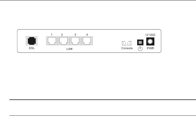
Rear Panel
The following figure illustrates the rear panel of your ADSL Router.
DSL: RJ-11 connector
LAN: Ethernet 10/100 Base-T auto-sensing
Reset: Reset to factory settings
Console: Console connector
 : Power switch
12VDC: Power connector
Note: The Router incorporates a four-port switch for connection to your local Ethernet network. The Ethernet ports are marked LOCAL, and are capable of operation at either 10 Mbps (10 BASE-T) or 100 Mbps (100 BASE-Tx).
2
Chapter 2: Installation
Chapter 2: Installation
Choosing a place for the ADSL Router
1.Place the ADSL Router close to ADSL wall outlet and power outlet for the cable to reach it easily.
2.Avoid placing the device in places where people may walk on the cables. Also keep it away from direct sunshine or heat sources.
3.Place the device on a flat and stable stand.
Connecting the ADSL Router
Follow the steps below to connect the related devices.
1.Remove the end of the phone line from your phone connector and plug it onto the “LINE” port of the POTS Splitter. Use another phone line to connect your phone and splitter. Plug this phone line onto the “PHONE” port of the ADSL splitter, and plug the other end of the line onto your phone.
2.Use the line to connect the ADSL splitter (MODEM port) and router’s DSL port.
3.Please attach one end of the Ethernet cable with RJ-45 connector to the LAN port of your ADSL Router.
4.Connect the other end of the cable to the Ethernet port of the client PC.
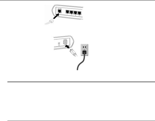
5.If you want to connect to a hub for used by many devices, please connect the other end to the uplink port of the hub.
3
ADSL Router User Manual
10/100BaseT Ethernet Hub
6.Connect the supplied power adapter to thePWR port of your ADSL Router, and plug the other end to a power outlet.
7.Turn on the power switch.
Note:
For Full Rate (G.dmt) standard, a POTS Splitter is necessary on subscriber’s premise to keep the telephone and ADSL signals separated, giving them the capability to provide simultaneous Internet access and telephone service on the same line. To connect a POTS Splitter:
1.Connect the port Phone to your telephone.
2.Connect the port Modem to your ADSL Router.
3.Connect the port Line to the ADSL wall jack.
4

Chapter 3: Connection Mode
Chapter 3: Connection Mode
Prior to configuring the ADSL Router, you must decide whether to configure the ADSL Router as a bridge or as a router. This chapter presents some deployment examples for your reference. Each mode includes its general configure procedures. For more detailed information about web configuration, refer to "Web Configuration".
Bridge Mode
Router Mode
MER Mode
PPPoA+ NAT Mode
PPPoE + NAT Mode
Multiple PVCs Mode
For making sure that you can connect the ADSL to your computer well and get into Internet successfully, please make sure the following first.
1.Make sure you have installed a network interface card onto your computer.
2.Make sure the connection between the ADSL and your computer is OK.
3.Check to see the TCP/IP protocol and set the IP address as “Auto Get IP Address”.
When you are sure all above is Ok, you can open the Browser and type in “192.168.100.100” and start to do the web configuration with different connection modes.
This chapter is going to introduce the function of each connection mode and tell you the basic configuring steps that you have to do. If you did not follow the configuring steps for using these connection modes, you might get some connection problems and cannot connect to Internet well.
5

ADSL Router User Manual
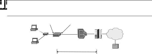
Bridge Mode
|
Default Private IP |
|
|
|
PC(s) |
192.168.100.100 |
|
|
|
|
|
Bridge |
|
|
|
Hub |
Mode |
Loop |
STM-1 |
|
|
|||
PPPoE |
|
|
|
ISP |
Client S/W |
|
ADSL |
|
|
|
|
|
BRAS |
|
|
|
Router |
DSLAM |
|
|
|
|
|
|
Public IP assigned |
|
AAA |
||
by BRAS |
|
|
|
|
|
|
|
|
RADIUS |
|
|
PPP over Ethernet |
Server |
|
|
|
|
||
|
|
BRAS Broadband Remote Access Server |
|
|
Description:
In this example, the ADSL Router acts as a bridge which bridging PC IP address from LAN to WAN. PC IP address can be a static public address that is pre-assigned by ISP or a dynamic public address that is assigned by ISP DHCP server, or can be got from PPPoE software.
Therefore, it does not require a public IP address. It only has a default private IP address (192.168.100.100) for management purpose.
Configuration:
1.Choose a client PC and set the IP as 192.168.100.x (x is between 2 and 254) and the gateway as 192.168.100.100.
2.Start up your browser and type 192.168.100.100as the address to enter the web-based manager.
3.Go to Configuration >WAN Configuration > Create a New PVC and select the Data Mode –RFC1483 Bridged. Then click Next button.
4.Enter the VPI/VCI values provided by your ISP and select the encapsulation type as LLC/SNAP or VC MUX. Then click Apply.
5.Save the configuration from System >Save Configuration and System >Restart to restart your router for initiating these settings.
6

Chapter 3: Connection Mode
Router Mode
|
|
Default Private IP |
|
|
|
|
192.168.100.100 for |
|
|
|
|
Management |
|
|
|
|
ADSL |
|
|
|
Hub |
Router |
Loop |
STM-1 |
|
|
|
|
ISP |
|
Public IP(s) |
|
BRAS |
|
|
|
DSLAM |
||
PC(s) |
Pre-assigned |
|
AAA |
|
by ISP (+ NAT) |
|
|||
|
|
|
||
|
|
|
|
RADIUS |
|
|
|
|
Server |
|
|
|
IP over ATM |
|
|
|
BRAS Broadband Remote Access Server |
||
Description:
In this deployment environment, we make up a private IP network of 192.168.100.100. NAT function is enabled (on ADSL Router or use another NAT box connected to hub) to support multiple clients to access the Router and some public servers (WWW, FTP).
If you apply for multiple IP addresses from your ISP, you can assign these public IP addresses to the ADSL Router and public server, e.g., Web or FTP server. Typically the first IP is network address, the second is used as router IP address and the last one is subnet broadcasting. Other remaining IP addresses can be assigned to PCs on the LAN.
For example: You are given the IP addresses 10.251.2.0 ~ 10.251.2.7. Then:
10.251.2.0 is network IP address 10.251.2.1 is assigned to router IP address. 10.251.2.7 is subnet broadcasting
10.251.2.2~10.251.2.6 can be assigned to public servers on the LAN.
Configuration:
1.Start up your browser and type 192.168.100.100as the address to enter this ADSL web-based manager.
2.Go to Configuration > WAN Configuration > Create a new PVC. and select the Data Mode –RFC1483 Routed. Then click Next button.
3.Enter the VPI/VCI values provided by your ISP and select the encapsulation type as LLC/SNAP or VC MUX. Then click Apply.
4. Set IP configuration for Local WAN IP Address. ChooseSpecify an IP Address |
item. Please set as the |
following example, |
|
IP Address: 10.3.80.105(should be the one that you get from ISP) |
|
Subnet Mask: 255.255.255.248(should be the one that you get from ISP) |
|
Check on Enable NAT on this interface and click Apply. |
|
5.Go to Configuration > LAN Configuration and set as the following Primary IP:192.168.100.100, Subnet Mask: 255.255.255.0
Secondary IP: 10.3.80.105, Subnet Mask: 255.255.255.248 (should be the one that you get from ISP)
Then click Apply.
6.Go to Configuration > IP Route and click Create a New Routeto add a new route.
Destination Address: |
leave default |
Netmask: |
leave default |
Forward packets to: |
Interface |
Then click Apply. |
|
7.Go to Configuration > DNSand enable DNS Relay setting and click Next. On the DNS Relay web page, enter the DNS Server IP address, for example 168.95.1.1 (you should get this value from your ISP).
8.Save the configuration from System >Save Configuration and System >Restart to restart your router for initiating these settings.
7

ADSL Router User Manual
9.Then you have set the web configuration successfully. And you can surf on the Internet.
Note:
If you have multiple PCs on the LAN, you may enable DHCP function on the private or public IP address. The ADSL Router implements a built-in DHCP server, which assigns IP addresses to the clients PCs on the LAN.
8

Chapter 3: Connection Mode
MER Mode
|
Default Private IP |
|
PC(s) |
192.168.100.100 |
|
|
MER |
|
|
Mode |
STM-1 |
|
Loop |
|
|
|
ISP |
S/W |
ADSL |
|
|
BRAS |
|
|
Router |
|
|
|
DSLAM |
|
Public IP assigned |
AAA |
|
by BRAS |
|
|
|
|
|
|
RADIUS |
|
|
Server |
|
|
MER |
|
BRAS: Broadband Remote Access Server |
|
Description:
In this deployment environment, we make up a private IP network of 192.168.100.100. NAT function is enabled to support multiple clients to access Internet.
In this example, the ADSL Router acts as NAT device which translate a private IP address into a public address. Therefore multiple users can share with one public IP address to access Internet through this router. The public address can be a static public address that is pre-assigned by ISP or a dynamic public address that is assigned by ISP DHCP server.
Configuration:
1.Start up your browser and type 192.168.100.100as the address to enter this ADSL web-based manager.
2.Go to Configuration > WAN Configuration > Create a new PVC. and select the Data Mode –RFC1483 MER. Then click Next button.
3.Enter the VPI/VCI values provided by your ISP and select the encapsulation type as LLC/SNAP or VC MUX. Then click Apply.
4. Set IP configuration for Local WAN IP Address. ChooseSpecify an IP Address |
item. Please set as the |
following example, |
|
IP Address: 10.3.86.105 (should be the one that you get from ISP) |
|
Subnet Mask: 255.255.255.0 (should be the one that you get from ISP) |
|
5.Go to Configuration > IP Route and click Create a new routeto add a new route. Configure the settings as the following example,
Destination Address: |
leave default |
Netmask: |
leave default |
Forward packets to: |
Gateway Address: 10.3.86.1 (you should get this value from your ISP) |
Then click Apply. |
|
6.Go to Configuration > DNSand enable DNS Relay setting and click Next. On the DNS Relay web page, enter the DNS Server IP address, for example 168.95.1.1 (you should get this value from your ISP).
7.Save the configuration from System >Save Configuration and System >Restart to restart your router for initiating these settings.
8.Then you have set the web configuration successfully. And you can surf on the Internet.
9
ADSL Router User Manual
PPPoA + NAT Mode
Default Private IP |
Dynamic Public IP |
92.168.100.3 192.168.100.100 |
assigned by BRAS |
Hub |
Ethernet |
ADSL |
|
|
Router |
Loop |
STM-1 |
|
|
ISP |
PPP + NAT + |
BRAS |
|
DHCP on |
||
DSLAM |
||
Private LAN |
AAA |
|
PC(s) |
||
192.168.100.2 |
RADIUS |
|
|
Server
PPP over ATM
BRAS: Broadband Remote Access Server
Description:
In this deployment environment, the PPPoA session is between the ADSL WAN interface and BRAS. The ADSL Router gets a public IP address from BRAS when connecting to DSLAM. The multiple client PCs will get private IP address from the DHCP server enabled on private LAN. The enabled NAT mechanism will translate the IP information for clients to access the Internet.
Configuration:
1.Start up your browser and type 192.168.100.100as the address to enter this ADSL web-based manager.
2. Go to Configuration > WAN Configuration > Create a new PVCand select the Data Mode – PPPoA. Then click Next button.
3.Enter the VPI/VCI values provided by your ISP and select the encapsulation type as LLC/SNAP or VC MUX.
4.Fill in the User Name and Password (you should get from ISP). Check on Enable NAT on this interface and click Apply.
5.Go to Configuration > DNSand enable DNS Relay setting and click Next. On the DNS Relay web page, enter the DNS Server IP address, for example 168.95.1.1 (you should get this value from your ISP).
6.Save the configuration by execute System >Save and System >Restart to restart your router for initiating these settings.
10

Chapter 3: Connection Mode
PPPoE + NAT Mode
Default Private IP 192.168.100.3 192.168.100.100
Hub |
Ethernet |
ADSL |
|
|
Router |
Loop |
STM-1 |
|
|
ISP |
|
PPPoE + NAT + |
BRAS |
|
DHCP on |
DSLAM |
PC(s) |
Private LAN |
AAA |
|
192.168.100.2 |
RADIUS |
|
|
|
Server |
|
PPP over Ethernet |
|
BRAS: Broadband Remote Access Server |
Description:
In this deployment environment, the PPPoE session is between the ADSL WAN interface and BRAS. The ADSL Router gets a public IP address from BRAS when connecting to DSLAM. The multiple client PCs will get private IP address from the DHCP server enabled on private LAN. The enabled NAT mechanism will translate the IP information for clients to access the Internet.
Configuration:
1.Start up your browser and type 192.168.100.100as the address to enter this ADSL web-based manager.
2. Go to Configuration > WAN Configuration > Create a new PVCand select the Data Mode – PPPoE. Then click Next button.
3.Enter the VPI/VCI values provided by your ISP and select the encapsulation type as LLC/SNAP or VC MUX.
4.Fill in the User Name and Password (you should get from ISP). Check on Enable NAT on this interface and click Apply.
5.Go to Configuration > DNSand enable DNS Relay setting and click Next. On the DNS Relay web page, enter the DNS Server IP address, for example 168.95.1.1 (you should get this value from your ISP).
6.Save the configuration by execute System >Save and System >Restart to restart your router for initiating these settings.
11

ADSL Router User Manual
PPPoE Relay
|
Default Private IP |
|
|
|
PC(s) |
192.168.100.100 |
|
|
|
|
|
Bridge |
|
|
|
Hub |
Mode |
Loop |
STM-1 |
|
|
|||
PPPoE |
|
|
|
ISP |
Client S/W |
|
ADSL |
|
|
|
|
|
BRAS |
|
|
|
Router |
DSLAM |
|
|
|
|
|
|
|
|
|
|
AAA |
|
|
|
|
RADIUS |
|
|
PPP over Ethernet |
Server |
|
|
|
|
||
|
|
BRAS: Broadband Remote Access Server |
|
|
Description:
In this example, the ADSL Router acts as a bridge which bridging PC IP address from LAN to WAN. Client PCs on the LAN should be equipped with PPPoE software to get public IP address from BRAS.
That is to say, the router does not require a public IP address. It only has a default private IP address (192.168.100.100) for management purpose.
Configuration:
1.Choose a client PC and set the IP as 192.168.100.x (x is between 2 and 254) and the gateway as 192.168.100.100. Or enter the IP address that came from the ISP DHCP server of the Router.
2.Start up your browser and type 192.168.100.100as the address to enter the web-based manager.
3.Go to Configuration >WAN Configuration > Create a New PVC and select the Data Mode –RFC1483 Bridged. Then click Next button.
4.Enter the VPI/VCI values provided by your ISP and select the encapsulation type as LLC/SNAP or VC MUX. Then click Apply.
5.Save the configuration from System >Save Configuration and System >Restart to restart your router for initiating these settings.
6.Run Windows PPPoE client application. Fill in the User Name and Password (you should get from ISP).
7.Click Connect.
12
Chapter 3: Connection Mode
Multiple PVCs Mode
128.12.0.0
|
ADSL |
(PPPoE) |
|
Hub |
Router |
||
PVC2 |
|||
|
|||
|
|
Loop |
 ISP a
ISP a 
Service PVC2b Aggregator
PVC1 |
STM-1 |
PVC1a |
ISP b |
|
|||
|
|
|
|
(IPoA) |
DSLAM |
140.196.0.0 |
|
|
|
||
|
|
|
PC(s)
Public IP(s)
Pre-assigned by ISPs
RADIUS
Server
Description:
As this ADSL Router supports multiple PVCs in the ADSL loop, you are allowed to configure several logical channels in one physical loop. You can use mixed encapsulation types by applying them to different PVCs. When the system starts up, it will connect to CO site through the PVCs according to the sequence they are created. Therefore the default route will be the last PVC you created. You can also modify the default route manually from the IPRoute page.
The traffic from CPE side will be sent to different PVCs according to the routing rules.
Configuration:
1.Start up your browser and type 192.168.100.100 as the address to enter this ADSL web-based manager.
2.Create the first PVC (e.g. PVC1) using the RFC1483data mode. Refer to the section of “Router Mode” for details.
3. Create the second PVC (e.g.PVC2) using the PPPoE data mode. Refer to the section of “PPPoE + NAT Mode” for details.
4.Save the configuration by execute System >Save and System >Restart to restart your router for initiating these settings.
13

ADSL Router User Manual
14
Chapter 4:Configuration
Chapter 4: Configuration
In order to access the Internet through the router, each host on your network must install/setup TCP/IP. Please follow the steps below for select a network adapter.
Setting TCP/IP on Client PC
To access the ADSL Router via Ethernet, the host computer must meet the following requirements:
With Ethernet network interface.
Must have TCP/IP installed.
Set client PC with obtain an IP address automatically or set fix IP address.
With a web browser installed: Internet Explorer 5.x or later.
The ADSL Router is configured with the default IP address of 192.168.100.100 and subnet mask of 255.255.255.0. As the DHCP server is Enable by default,The DHCP clients should be able to
access the ADSL Router. Or you could assign an IP address to the host PC first for initial configuration.
You also can manage the ADSL Router through a web browser-based manager:ADSL ROUTER CONTROL PANEL. The ADSL Router manager uses the HTTP protocol via a web browser to allow you to set up and manage the device.
To configure the device via web browser, at least one properly-configured PC must be connected to the network (either connected directly or through an external hub/switch to the LAN port of the device).
If TCP/IP is not already installed, follow the steps below for installation.
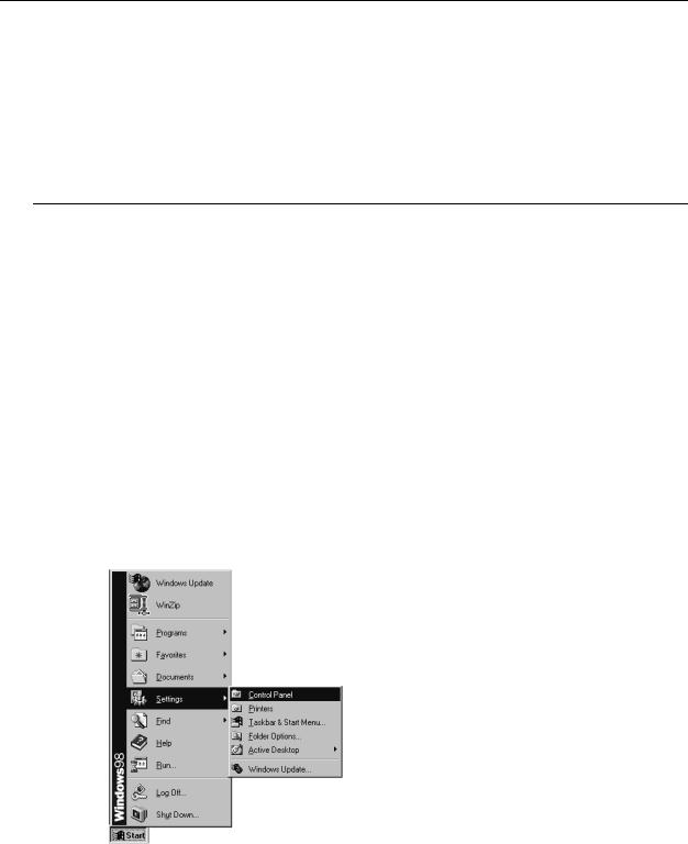
For Windows 98
1.Click on the Start menu, point toSettings and click on Control Panel.
2.Double-click the Network icon.
15

ADSL Router User Manual
3.The Network window appears. On the Configuration tab, check out the list of installed network components.
Option 1:If you haveno TCP/IP protocol, clickAdd .
Option 2:If you have TCP/IP protocol, go to Step 6.
Your network interface card.
Check out if TCP/IP for your NIC is installed or not.
4. Highlight Protocol and click Add.
16
 Loading...