


INSTALLATION
MANUAL
CONTENTS
GENERAL . . . . . . . . . . . . . . . . . . . . . . . . . . . . . . . . . . . . . . 5 SAFETY CONSIDERATIONS . . . . . . . . . . . . . . . . . . . . . . . 5 INSPECTION . . . . . . . . . . . . . . . . . . . . . . . . . . . . . . . . . . . . 5 REFERENCE . . . . . . . . . . . . . . . . . . . . . . . . . . . . . . . . . . . . 6 RENEWAL PARTS . . . . . . . . . . . . . . . . . . . . . . . . . . . . . . . 6 APPROVALS . . . . . . . . . . . . . . . . . . . . . . . . . . . . . . . . . . . . 6 NOMENCLATURE . . . . . . . . . . . . . . . . . . . . . . . . . . . . . . . . 7 INSTALLATION . . . . . . . . . . . . . . . . . . . . . . . . . . . . . . . . . . 8 OPERATION . . . . . . . . . . . . . . . . . . . . . . . . . . . . . . . . . . . 46 START-UP (COOLING) . . . . . . . . . . . . . . . . . . . . . . . . . . . 56 START-UP (GAS HEAT) . . . . . . . . . . . . . . . . . . . . . . . . . . 56 TROUBLESHOOTING . . . . . . . . . . . . . . . . . . . . . . . . . . . . 61
See following pages for a complete Table of Contents.
NOTES, CAUTIONS AND WARNINGS
The installer should pay particular attention to the words: NOTE, CAUTION, and WARNING. Notes are intended to clarify or make the installation easier. Cautions are given to prevent equipment damage. Warnings are given to alert installer that personal injury and/or equipment damage may result if installation procedure is not handled properly.
CAUTION: READ ALL SAFETY GUIDES BEFORE YOU
BEGIN TO INSTALL YOUR UNIT.
SAVE THIS MANUAL
MagnaDRY™
SINGLE PACKAGE AIR CONDITIONERS AND SINGLE PACKAGE GAS/ELECTRIC UNITS DR090, 120 and 150
DR090 and 120
DR150
Tested in accordance with:
127878-YIM-B-0606

127878-YIM-B-0606
TABLE OF CONTENTS
GENERAL . . . . . . . . . . . . . . . . . . . . . . . . . . . . . . . . . . . . . . 5 SAFETY CONSIDERATIONS . . . . . . . . . . . . . . . . . . . . . . . 5 INSPECTION . . . . . . . . . . . . . . . . . . . . . . . . . . . . . . . . . . . . 5 REFERENCE . . . . . . . . . . . . . . . . . . . . . . . . . . . . . . . . . . . . 6 RENEWAL PARTS . . . . . . . . . . . . . . . . . . . . . . . . . . . . . . . 6 APPROVALS . . . . . . . . . . . . . . . . . . . . . . . . . . . . . . . . . . . . 6 NOMENCLATURE . . . . . . . . . . . . . . . . . . . . . . . . . . . . . . . . 7
INSTALLATION . . . . . . . . . . . . . . . . . . . . . . . . . . . . . . . . . . 8
INSTALLATION SAFETY INFORMATION . . . . . . . . . . . . . . 8 PRECEDING INSTALLATION. . . . . . . . . . . . . . . . . . . . . . . . 8 LIMITATIONS . . . . . . . . . . . . . . . . . . . . . . . . . . . . . . . . . . . . 9 LOCATION . . . . . . . . . . . . . . . . . . . . . . . . . . . . . . . . . . . . . 11 RIGGING AND HANDLING. . . . . . . . . . . . . . . . . . . . . . . . . 12
. . . . . . . . . . . . . . . . . . . . . . . . . . . . . . . . . . . . . . . . . . . . . . . 13 CLEARANCES . . . . . . . . . . . . . . . . . . . . . . . . . . . . . . . . . . 13 DUCTWORK . . . . . . . . . . . . . . . . . . . . . . . . . . . . . . . . . . . . 17 DUCT COVERS . . . . . . . . . . . . . . . . . . . . . . . . . . . . . . . . . 17 CONDENSATE DRAIN . . . . . . . . . . . . . . . . . . . . . . . . . . . . 18 COMPRESSORS . . . . . . . . . . . . . . . . . . . . . . . . . . . . . . . . 18 FILTERS . . . . . . . . . . . . . . . . . . . . . . . . . . . . . . . . . . . . . . . 18 THERMOSTAT WIRING . . . . . . . . . . . . . . . . . . . . . . . . . . . 19 POWER AND CONTROL WIRING . . . . . . . . . . . . . . . . . . . 19 POWER WIRING DETAIL . . . . . . . . . . . . . . . . . . . . . . . . . . 19 OPTIONAL ELECTRIC HEAT . . . . . . . . . . . . . . . . . . . . . . . 25 OPTIONAL GAS HEAT . . . . . . . . . . . . . . . . . . . . . . . . . . . . 26
GAS PIPING. . . . . . . . . . . . . . . . . . . . . . . . . . . . . . . . . . . 26 GAS CONNECTION. . . . . . . . . . . . . . . . . . . . . . . . . . . . . 27 LP UNITS, TANKS AND PIPING . . . . . . . . . . . . . . . . . . . 27 VENT AND COMBUSTION AIR . . . . . . . . . . . . . . . . . . . . 28 OPTIONS/ACCESSORIES . . . . . . . . . . . . . . . . . . . . . . . . . 28 ELECTRIC HEAT . . . . . . . . . . . . . . . . . . . . . . . . . . . . . . . 28 MOTORIZED OUTDOOR DAMPER . . . . . . . . . . . . . . . . 28 ECONOMIZER . . . . . . . . . . . . . . . . . . . . . . . . . . . . . . . . . 28 POWER EXHAUST . . . . . . . . . . . . . . . . . . . . . . . . . . . . . 28 RAIN HOOD . . . . . . . . . . . . . . . . . . . . . . . . . . . . . . . . . . . 29
ECONOMIZER AND POWER EXHAUST SET POINT ADJUSTMENTS AND INFORMATION. . . . . . . . . . . . . . . . . . 29 MINIMUM POSITION ADJUSTMENT . . . . . . . . . . . . . . . 29 ENTHALPY SET POINT ADJUSTMENT . . . . . . . . . . . . . 29 POWER EXHAUST DAMPER SET POINT (WITH OR
WITHOUT POWER EXHAUST) . . . . . . . . . . . . . . . . . . . 29 INDOOR AIR QUALITY AQ . . . . . . . . . . . . . . . . . . . . . . . 29 PHASING . . . . . . . . . . . . . . . . . . . . . . . . . . . . . . . . . . . . . . 31 BLOWER ROTATION . . . . . . . . . . . . . . . . . . . . . . . . . . . . . 31 BELT TENSION. . . . . . . . . . . . . . . . . . . . . . . . . . . . . . . . . . 31
AIR BALANCE . . . . . . . . . . . . . . . . . . . . . . . . . . . . . . . . . . 44
CHECKING AIR QUANTITY . . . . . . . . . . . . . . . . . . . . . . . . 44 METHOD ONE . . . . . . . . . . . . . . . . . . . . . . . . . . . . . . . . . 44 METHOD TWO. . . . . . . . . . . . . . . . . . . . . . . . . . . . . . . . . 44 SUPPLY AIR DRIVE ADJUSTMENT . . . . . . . . . . . . . . . . . 45
OPERATION . . . . . . . . . . . . . . . . . . . . . . . . . . . . . . . . . . . 46
SEQUENCE OF OPERATIONS OVERVIEW . . . . . . . . . . . 46 COOLING SEQUENCE OF OPERATION . . . . . . . . . . . . . 47 CONTINUOUS BLOWER . . . . . . . . . . . . . . . . . . . . . . . . 47 INTERMITTENT BLOWER . . . . . . . . . . . . . . . . . . . . . . . 47 NO OUTDOOR AIR OPTIONS . . . . . . . . . . . . . . . . . . . . 47 ECONOMIZER WITH SINGLE ENTHALPY SENSOR - . 47 ECONOMIZER WITH DUAL ENTHALPY SENSORS - . . 47 ECONOMIZER WITH POWER EXHAUST - . . . . . . . . . . 47 MOTORIZED OUTDOOR AIR DAMPERS - . . . . . . . . . . 47 COOLING OPERATION ERRORS . . . . . . . . . . . . . . . . . 48 HIGH-PRESSURE LIMIT SWITCH . . . . . . . . . . . . . . . . . 48 LOW-PRESSURE LIMIT SWITCH. . . . . . . . . . . . . . . . . . 48 FREEZESTAT . . . . . . . . . . . . . . . . . . . . . . . . . . . . . . . . . 48 LOW AMBIENT COOLING . . . . . . . . . . . . . . . . . . . . . . . 48 SAFETY CONTROLS . . . . . . . . . . . . . . . . . . . . . . . . . . . . . 48 COMPRESSOR PROTECTION . . . . . . . . . . . . . . . . . . . . . 49 FLASH CODES . . . . . . . . . . . . . . . . . . . . . . . . . . . . . . . . 49 RESET . . . . . . . . . . . . . . . . . . . . . . . . . . . . . . . . . . . . . . . 49 REHEAT MODE SEQUENCE OF OPERATION . . . . . . . . 49 “NORMAL” MODE . . . . . . . . . . . . . . . . . . . . . . . . . . . . . . 49 "ALTERNATE” MODE . . . . . . . . . . . . . . . . . . . . . . . . . . . 49 ELECTRIC HEATING SEQUENCE OF OPERATIONS . . . 53 ELECTRIC HEAT OPERATION ERRORS . . . . . . . . . . . . . 53 TEMPERATURE LIMIT . . . . . . . . . . . . . . . . . . . . . . . . . . 53 SAFETY CONTROLS . . . . . . . . . . . . . . . . . . . . . . . . . . . 53 LIMIT SWITCH (LS) . . . . . . . . . . . . . . . . . . . . . . . . . . . . . 53 FLASH CODES . . . . . . . . . . . . . . . . . . . . . . . . . . . . . . . . 53 RESET . . . . . . . . . . . . . . . . . . . . . . . . . . . . . . . . . . . . . . . 53 ELECTRIC HEAT ANTICIPATOR SETPOINTS . . . . . . . . . 53 GAS HEATING SEQUENCE OF OPERATIONS . . . . . . . . 54 IGNITION CONTROL BOARD . . . . . . . . . . . . . . . . . . . . . . 54 FIRST STAGE OF HEATING. . . . . . . . . . . . . . . . . . . . . . 54 SECOND STAGE OF HEATING . . . . . . . . . . . . . . . . . . . 54 RETRY OPERATION. . . . . . . . . . . . . . . . . . . . . . . . . . . . 54 RECYCLE OPERATION . . . . . . . . . . . . . . . . . . . . . . . . . 54 GAS HEATING OPERATION ERRORS . . . . . . . . . . . . . . . 54 LOCK-OUT. . . . . . . . . . . . . . . . . . . . . . . . . . . . . . . . . . . . 54 TEMPERATURE LIMIT . . . . . . . . . . . . . . . . . . . . . . . . . . 54 FLAME SENSE . . . . . . . . . . . . . . . . . . . . . . . . . . . . . . . . 54 GAS VALVE. . . . . . . . . . . . . . . . . . . . . . . . . . . . . . . . . . . 55 SAFETY CONTROLS . . . . . . . . . . . . . . . . . . . . . . . . . . . . . 55 LIMIT SWITCH (LS) . . . . . . . . . . . . . . . . . . . . . . . . . . . . . 55 AUXILIARY LIMIT SWITCH (ALS). . . . . . . . . . . . . . . . . . 55 PRESSURE SWITCH (PS) . . . . . . . . . . . . . . . . . . . . . . . 55 ROLLOUT SWITCH (ROS) . . . . . . . . . . . . . . . . . . . . . . . 55 INTERNAL MICROPROCESSOR FAILURE . . . . . . . . . . 55 FLASH CODES . . . . . . . . . . . . . . . . . . . . . . . . . . . . . . . . 55 RESETS. . . . . . . . . . . . . . . . . . . . . . . . . . . . . . . . . . . . . . 55 GAS HEAT ANTICIPATOR SETPOINTS . . . . . . . . . . . . . . 55
START-UP (COOLING) . . . . . . . . . . . . . . . . . . . . . . . . . . . 56
PRESTART CHECK LIST. . . . . . . . . . . . . . . . . . . . . . . . . . 56 OPERATING INSTRUCTIONS . . . . . . . . . . . . . . . . . . . . . . 56
2 |
Unitary Products Group |

127878-YIM-B-0606
POST START CHECK LIST. . . . . . . . . . . . . . . . . . . . . . . . .56
START-UP (GAS HEAT) . . . . . . . . . . . . . . . . . . . . . . . . . . 56
PRE-START CHECK LIST. . . . . . . . . . . . . . . . . . . . . . . . . .56 OPERATING INSTRUCTIONS . . . . . . . . . . . . . . . . . . . . . .56 LIGHTING THE MAIN BURNERS. . . . . . . . . . . . . . . . . . .56 POST START CHECKLIST . . . . . . . . . . . . . . . . . . . . . . . . .56 SHUT DOWN . . . . . . . . . . . . . . . . . . . . . . . . . . . . . . . . . . . .57 MANIFOLD GAS PRESSURE ADJUSTMENT . . . . . . . . . .57
CHECKING GAS INPUT . . . . . . . . . . . . . . . . . . . . . . . . . . . 57 NATURAL GAS. . . . . . . . . . . . . . . . . . . . . . . . . . . . . . . . . 57 ADJUSTMENT OF TEMPERATURE RISE . . . . . . . . . . . . . 59 BURNERS/ORIFICES INSPECTION/SERVICING . . . . . . . 59
TROUBLESHOOTING . . . . . . . . . . . . . . . . . . . . . . . . . . . 61
PREDATOR® FLASH CODES . . . . . . . . . . . . . . . . . . . . . . 61 COOLING TROUBLESHOOTING GUIDE. . . . . . . . . . . . . . 66 GAS HEAT TROUBLESHOOTING GUIDE . . . . . . . . . . . . . 69
LIST OF FIGURES
Fig. # |
Pg. # |
1 UNIT SHIPPING BRACKET . . . . . . . . . . . . . . . . . . . . . . . . 8
2 CONDENSER COVERING . . . . . . . . . . . . . . . . . . . . . . . . . 8
3 COMPRESSOR SECTION . . . . . . . . . . . . . . . . . . . . . . . . . 8
4 PREDATOR MAGNADRY™ DR090 & 120
COMPONENT LOCATION . . . . . . . . . . . . . . . . . . . . . . . . 10
5 PREDATOR MAGNADRY™ DR150
COMPONENT LOCATION . . . . . . . . . . . . . . . . . . . . . . . . 11
6 DR090 & 120 UNITS 4 POINT LOAD . . . . . . . . . . . . . . . . 12
7 DR150 UNIT 4 POINT LOAD. . . . . . . . . . . . . . . . . . . . . . . 12
8 DR090 & 120 UNITS 6 POINT LOAD . . . . . . . . . . . . . . . . 12
9 DR150 UNIT 6 POINT LOAD. . . . . . . . . . . . . . . . . . . . . . . 13
10 UNIT CENTER OF GRAVITY
(DR090, 120) . . . . . . . . . . . . . . . . . . . . . . . . . . . . . . . . . . . 13
11 UNIT CENTER OF GRAVITY - DR150 . . . . . . . . . . . . . . . 13
12 DR090 & 120 UNIT DIMENSIONS . . . . . . . . . . . . . . . . . . 14
13 DR150 UNIT DIMENSIONS. . . . . . . . . . . . . . . . . . . . . . . . 14
14 BOTTOM DUCT OPENINGS (FROM ABOVE) . . . . . . . . . 15
15 DR090 & 120 REAR DUCT DIMENSIONS . . . . . . . . . . . . 16
16 DR150 REAR DUCT DIMENSIONS . . . . . . . . . . . . . . . . . 16
17 PREDATOR® ROOF CURB DIMENSIONS . . . . . . . . . . . 17
18 SUNLINE™ TO PREDATOR® TRANSITION
ROOF CURBS . . . . . . . . . . . . . . . . . . . . . . . . . . . . . . . . . . 17
19 SIDE PANELS WITH HOLE PLUGS . . . . . . . . . . . . . . . . . 18
20 RETURN DOWNFLOW PLENUM WITH PANEL . . . . . . . 18
21 DISCHARGE PANEL IN PLACE . . . . . . . . . . . . . . . . . . . . 18
Fig. # |
Pg. # |
22 CONDENSATE DRAIN . . . . . . . . . . . . . . . . . . . . . . . . . . . 18 23 TYPICAL LOW VOLTAGE FIELD WIRING . . . . . . . . . . . 20
24 FIELD WIRING DISCONNECT - COOLING UNIT WITH/WITHOUT ELECTRIC HEAT . . . . . . . . . . . . . . . . . 21
25 FIELD WIRING DISCONNECT-COOLING UNIT
WITH GAS HEAT . . . . . . . . . . . . . . . . . . . . . . . . . . . . . . . 21 26 SIDE ENTRY GAS PIPING . . . . . . . . . . . . . . . . . . . . . . . . 26 27 BOTTOM ENTRY GAS PIPING . . . . . . . . . . . . . . . . . . . . 26 28 ENTHALPY SET POINT CHART . . . . . . . . . . . . . . . . . . . 30 29 HONEYWELL ECONOMIZER CONTROL W7212 . . . . . . 30 30 BELT ADJUSTMENT . . . . . . . . . . . . . . . . . . . . . . . . . . . . 31 31 DRY COIL DELTA P . . . . . . . . . . . . . . . . . . . . . . . . . . . . . 45 32 REHEAT CONTROL BOARD . . . . . . . . . . . . . . . . . . . . . . 50 33 DR090 AND DR120 REHEAT CONTROLS . . . . . . . . . . . 51 34 DR150 REHEAT CONTROLS . . . . . . . . . . . . . . . . . . . . . 52 35 TYPICAL FLAME . . . . . . . . . . . . . . . . . . . . . . . . . . . . . . . 56 36 TYPICAL GAS VALVE . . . . . . . . . . . . . . . . . . . . . . . . . . . 59 37 CHARGING CHART DR090 . . . . . . . . . . . . . . . . . . . . . . . 60 38 CHARGING CHART DR120 . . . . . . . . . . . . . . . . . . . . . . . 60 39 CHARGING CHART DR150 . . . . . . . . . . . . . . . . . . . . . . . 61 40 UNIT CONTROL BOARD . . . . . . . . . . . . . . . . . . . . . . . . . 62 41 BASIC TROUBLESHOOTING FLOWCHART . . . . . . . . . 64 42 POWER ON FLOW CHART . . . . . . . . . . . . . . . . . . . . . . . 64 43 TRIP FAILURE FLOW CHART . . . . . . . . . . . . . . . . . . . . . 65
LIST OF TABLES
Tbl. # |
Pg. # |
1 UNIT VOLTAGE LIMITATIONS . . . . . . . . . . . . . . . . . . . . . 11 2 UNIT TEMPERATURE LIMITATIONS. . . . . . . . . . . . . . . . 11 3 UNIT WEIGHTS . . . . . . . . . . . . . . . . . . . . . . . . . . . . . . . . . 13 4 4 POINT LOAD WEIGHT . . . . . . . . . . . . . . . . . . . . . . . . . . 13
Tbl. # |
Pg. # |
5 6 POINT LOAD WEIGHT . . . . . . . . . . . . . . . . . . . . . . . . . 13 6 UNIT CLEARANCES. . . . . . . . . . . . . . . . . . . . . . . . . . . . . 15 7 CONTROL WIRE SIZES . . . . . . . . . . . . . . . . . . . . . . . . . . 19
8 ELECTRICAL DATA - DR090 WITHOUT POWERED CONVENIENCE OUTLET. . . . . . . . . . . . . . . . . . . . . . . . . 22
Unitary Products Group |
3 |

127878-YIM-B-0606
Tbl. # |
Pg. # |
9 ELECTRICAL DATA - DR090 WITH POWERED CONVENIENCE OUTLET . . . . . . . . . . . . . . . . . . . . . . . . . 22
10 ELECTRICAL DATA - DR120 W/O PWRD
CONVENIENCE OUTLET . . . . . . . . . . . . . . . . . . . . . . . . . 23
11 ELECTRICAL DATA - DR120 W/PWRD
CONVENIENCE OUTLET . . . . . . . . . . . . . . . . . . . . . . . . . 23
12 ELECTRICAL DATA - DR150 W/O PWRD
CONVENIENCE OUTLET . . . . . . . . . . . . . . . . . . . . . . . . . 24
13 ELECTRICAL DATA - DR150 W/PWRD
CONVENIENCE OUTLET . . . . . . . . . . . . . . . . . . . . . . . . . 24 14 PHYSICAL DATA . . . . . . . . . . . . . . . . . . . . . . . . . . . . . . . 25 15 MINIMUM SUPPLY AIR CFM . . . . . . . . . . . . . . . . . . . . . . 25 16 GAS APPLICATION DATA . . . . . . . . . . . . . . . . . . . . . . . . 26 17 GAS PIPE SIZING - CAPACITY OF PIPE . . . . . . . . . . . . 26 18 SUPPLY AIR LIMITATIONS . . . . . . . . . . . . . . . . . . . . . . . 31 19 BLOWER PERFORMANCE DR090 SIDE FLOW . . . . . . 32
20 BLOWER PERFORMANCE DR090 SIDE FLOW ECONOMIZER . . . . . . . . . . . . . . . . . . . . . . . . . . . . . . . . . 33
21 BLOWER PERFORMANCE DR090 DOWN FLOW . . . . . 34
22 BLOWER PERFORMANCE DR090 DOWN FLOW ECONOMIZER . . . . . . . . . . . . . . . . . . . . . . . . . . . . . . . . . 35
23 BLOWER PERFORMANCE DR120 SIDE FLOW . . . . . . 36
24 BLOWER PERFORMANCE DR120 SIDE FLOW ECONOMIZER . . . . . . . . . . . . . . . . . . . . . . . . . . . . . . . . . 37
Tbl. # |
Pg. # |
25 BLOWER PERFORMANCE DR120 DOWN FLOW . . . . . 38
26 BLOWER PERFORMANCE DR120 DOWN FLOW ECONOMIZER . . . . . . . . . . . . . . . . . . . . . . . . . . . . . . . . . 39
27 BLOWER PERFORMANCE DR150 SIDE FLOW . . . . . . 40
28 BLOWER PERFORMANCE DR150 SIDE FLOW ECONOMIZER . . . . . . . . . . . . . . . . . . . . . . . . . . . . . . . . . 41
29 BLOWER PERFORMANCE DR150 DOWN FLOW . . . . . 42
30 BLOWER PERFORMANCE DR150 DOWN FLOW ECONOMIZER . . . . . . . . . . . . . . . . . . . . . . . . . . . . . . . . . 43
31 INDOOR BLOWER SPECIFICATIONS . . . . . . . . . . . . . . 43 32 POWER EXHAUST SPECIFICATIONS . . . . . . . . . . . . . . 44 33 ADDITIONAL STATIC RESISTANCE . . . . . . . . . . . . . . . 46 34 MOTOR SHEAVE DATUM DIAMETERS . . . . . . . . . . . . . 46 35 ELECTRIC HEAT LIMIT SETTING . . . . . . . . . . . . . . . . . 53 36 ELECTRIC HEAT ANTICIPATOR SETPOINTS . . . . . . . 54 37 GAS HEAT LIMIT CONTROL SETTINGS . . . . . . . . . . . . 55 38 GAS HEAT ANTICIPATOR SETPOINTS . . . . . . . . . . . . . 56 39 GAS HEAT STAGES . . . . . . . . . . . . . . . . . . . . . . . . . . . . 57 40 GAS RATE CUBIC FEET PER HOUR . . . . . . . . . . . . . . . 58 41 UNIT CONTROL BOARD FLASH CODES . . . . . . . . . . . 62 42 IGNITION CONTROL FLASH CODES. . . . . . . . . . . . . . . 63 43 REHEAT CONTROL BOARD FLASH CODES . . . . . . . . 63
4 |
Unitary Products Group |
127878-YIM-B-0606
GENERAL
YORK® Predator MagnaDRY™ units are single package air conditioners with optional gas heating designed for outdoor installation on a rooftop or slab and for non-residential use. These units can be equipped with factory or field installed electric heaters for heating applications.
These units are completely assembled on rigid, permanently attached base rails. All piping, refrigerant charge, and electrical wiring is factory installed and tested. The units require electric power, gas supply (where applicable), and duct connections. The electric heaters have nickel-chrome elements and utilize single-point power connection.
SAFETY CONSIDERATIONS
Should overheating occur, or the gas supply fail to shut off, shut off the manual gas valve to the furnace before shutting off the electrical supply.
Do not use this furnace if any part has been under water. Immediately call a qualified service technician to inspect the furnace and to replace any part of the control system and any gas control which has been under water.
Due to system pressure, moving parts, and electrical components, installation and servicing of air conditioning equipment can be hazardous. Only qualified, trained service personnel should install, repair, or service this equipment. Untrained personnel can perform basic maintenance functions of cleaning coils and filters and replacing filters.
Observe all precautions in the literature, labels, and tags accompanying the equipment whenever working on air conditioning equipment. Be sure to follow all other applicable safety precautions and codes including ANSI Z223.1 or CSAB149.1- latest edition.
Wear safety glasses and work gloves. Use quenching cloth and have a fire extinguisher available during brazing operations.
If the information in this manual is not followed exactly, a fire or explosion may result causing property damage, personal injury or loss of life.
Do not store or use gasoline or other flammable vapors and liquids in the vicinity of this or any other appliance.
WHAT TO DO IF YOU SMELL GAS:
a.Do not try to light any appliance.
b.Do not touch any electrical switch; do not use any phone in your building.
c.Immediately call your gas supplier from a neighbor’s phone. Follow the gas supplier’s instructions.
d.If you cannot reach your gas supplier, call the fire department.
Installation and service must be performed by a qualified installer, service agency or the gas supplier.
INSPECTION
As soon as a unit is received, it should be inspected for possible damage during transit. If damage is evident, the extent of the damage should be noted on the carrier’s freight bill. A separate request for inspection by the carrier’s agent should be made in writing.
This furnace is not to be used for temporary heating of buildings or structures under construction.
Before performing service or maintenance operations on unit, turn off main power switch to unit. Electrical shock could cause personal injury. Improper installation, adjustment, alteration, service or maintenance can cause injury or property damage. Refer to this manual. For assistance or additional information consult a qualified installer, service agency or the gas supplier.
Unitary Products Group |
5 |
127878-YIM-B-0606
REFERENCE
Additional information is available in the following reference forms:
•Technical Guide - DR090-150, 246721
•General Installation - DR090 - 150, 127878
•Pre-start & Post-start Check List
•Economizer Accessory -
Downflow Factory Installed
Downflow Field Installed
Horizontal Field Installed
•Motorized Outdoor Air Damper
•Manual Outdoor Air Damper (0-100%)
•Manual Outdoor Air Damper (0-35%)
•Gas Heat Propane Conversion Kit
•Gas Heat High Altitude Kit (Natural Gas)
•Gas Heat High Altitude Kit (Propane)
•–60°F Gas Heat Kit
•Electric Heater Accessory
RENEWAL PARTS
Contact your local York® parts distribution center for authorized replacement parts.
APPROVALS
Design certified by CSA as follows:
1.For use as a cooling only unit, cooling unit with supplemental electric heat or a forced air furnace.
2.For outdoor installation only.
3.For installation on combustible material and may be installed directly on combustible flooring or, in the U.S., on wood flooring or Class A, Class B or Class C roof covering materials.
4.For use with natural gas (convertible to LP with kit).
This product must be installed in strict compliance with the enclosed installation instructions and any applicable local, state, and national codes including, but not limited to, building, electrical, and mechanical codes.
Incorrect installation may create a condition where the operation of the product could cause personal injury or property damage.
The installer should pay particular attention to the words: NOTE, CAUTION, and WARNING. NOTES are intended to clarify or make the installation easier. CAUTIONS are given to prevent equipment damage. WARNINGS are given to alert installer that personal injury and/or equipment damage may result if installation procedure is not handled properly.
6 |
Unitary Products Group |
127878-YIM-B-0606
NOMENCLATURE
7.5-12.5 Ton York® Model Number Nomenclature
D R 090 N10 A 2 A AA 3 0 1 2 4 A
Product Category
D = A/C, Single Pkg., R-22
Product Identifier
R = REHEAT
Nominal Cooling Capacity
090 = 7.5 Ton
120 = 10.0 Ton
150 = 12.5 Ton
Heat Type and Nominal Heat Capacity
C00 = Cooling Only. No heat installed
Gas Heat Options
N10 = 100 MBH Output Aluminized Steel
N15 = 150 MBH Output Aluminized Steel
N20 = 200 MBH Output Aluminized Steel
S10 = 100 MBH Output Stainless Steel
S15 = 150 MBH Output Stainless Steel
S20 = 200 MBH Output Stainless Steel
Electric Heat Options
E09 = 9 KW
E18 = 18 KW
E24 = 24 KW
E36 = 36 KW
E54 = 54 KW
Airflow
A = Std. Motor
B = Std. Motor/Econo./Barometric Relief (Downflow
Only)
C = Std. Motor/Econo./Power Exhaust (Downflow Only)
D = Std. Motor/Motorized Damper (Downflow Only)
E = Std. Motor/Horizontal Economizer (No Baro.)
F = Std. Motor/Slab Econo./Power Exhaust
(Downflow Only)
G = Std. Motor/Slab Econo./Barometric Relief
(Downflow Only)
N = Hi Static Mtr.
P = Hi Static Mtr./Econo./Barometric Relief
(Downflow Only)
Q = Hi Static Mtr./Econo./Power Exhaust
(Downflow Only)
R = Hi Static Mtr./Motorized Damper (Downflow Only)
S = Hi Static Mtr./Horizontal Economizer (No Baro.)
T = Hi Static Mtr./Slab Econo./Power Exhaust
(Downflow Only)
U = Hi Static Mtr./Slab Econo./Barometric Relief
(Downflow only)
Voltage
2 = 208/230-3-60
4 = 460-3-60
5 = 575-3-60
Product Style
A = Style A
B = Style B
C = Style C
Configuration Options (not required for all units)
These four digits will not be assigned until a quote is requested, or an order placed.
SS Drain Pan
CPC Controller, DFS, APS
Johnson Controller, DFS, APS
Honeywell Controller, DFS, APS
Novar Controller, DFS, APS
Simplicity IntelliComfort Controller
Simplicity IntelliComfort Controller w/ModLinc
2" Pleated filters
BAS Ready Unit with Belimo Economizer
Shipping Bag
Any Combination of Additional Options that Don’t Have an Option Code Pre-assigned
|
|
Product Generation |
|
|
|
|
|
|
3 |
= Third Generation |
|
|
4 |
= Fourth Generation |
|
|
|
|
|
|
|
|
|
|
|
|
Additional Options |
AA = None |
RC = Coil Guard, Shipping Bag & American Flag |
AB = Phase Monitor |
TA = Technicoat Condenser Coil |
AC = Coil Guard |
TJ = Technicoat Evaporator Coil |
AD = Dirty Filter Switch |
TS = Technicoat Evaporator & Condenser Coils |
AE = Phase Monitor & Coil Guard |
|
AF = Phase Monitor & Dirty Filter Switch |
|
AG = Coil Guard & Dirty Filter Switch |
|
AH = Phase Monitor, Coil Guard & Dirty Filter Switch |
|
|
|
ZZ= If desired option combination is not listed above, ZZ will be assigned and configuration options will be located in digits 15-18.
Installation Options
A = No Options Installed
B = Option 1
C = Option 2
D = Options 1 & 2
E = Option 3
F = Option 4
G = Options 1 & 3
H = Options 1 & 4
J = Options 1, 2 & 3
K = Options 1, 2, & 4
L = Options 1,3 & 4
M = Options 1, 2, 3, & 4
N = Options 2 & 3
P = Options 2 & 4
Q = Options 2, 3, & 4
R = Options 3 & 4
S = Option 5
T = Options 1 & 5
U = Options 1, 3, & 5
V = Options 1, 4, & 5
W = Options 1, 3, 4, & 5
X = Options 3 & 5
Y = Options 4 & 5
Z = Options 3, 4 & 5
Options
1 = Disconnect
2 = Non-Pwr'd Conv. Outlet
3 = Smoke Detector S.A.
4 = Smoke Detector R.A.
5 = Pwr'd Conv. Outlet
Unitary Products Group |
7 |
127878-YIM-B-0606
INSTALLATION
INSTALLATION SAFETY INFORMATION
Read these instructions before continuing this appliance installation. This is an outdoor combination heating and cooling unit. The installer must assure that these instructions are made available to the consumer and with instructions to retain them for future reference.
1.Refer to the furnace rating plate for the approved type of gas for this furnace.
2.Install this furnace only in a location and position as specified on Page 11 of these instructions.
3.Never test for gas leaks with an open flame. Use commercially available soap solution made specifically for the detection of leaks when checking all connections, as specified on Pages 8, 27, 28 and 57 of these instructions.
4.Always install furnace to operate within the furnace's intended temperature-rise range with the duct system and within the allowable external static pressure range, as specified on the unit name/rating plate, specified on Page 59 of these instructions.
5.This equipment is not to be used for temporary heating of buildings or structures under construction.
FIRE OR EXPLOSION HAZARD
Failure to follow the safety warning exactly could result in serious injury, death or property damage.
Never test for gas leaks with an open flame. use a commercially available soap solution made specifically for the detection of leaks to check all connections. A fire or explosion may result causing property damage, personal injury or loss of life.
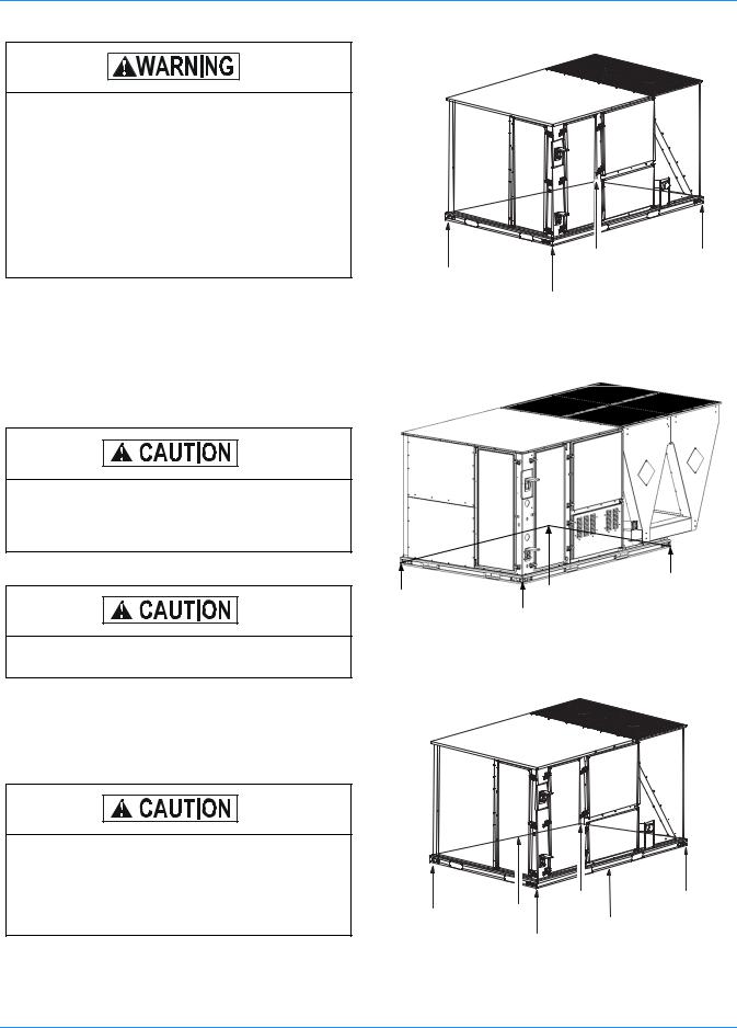
PRECEDING INSTALLATION
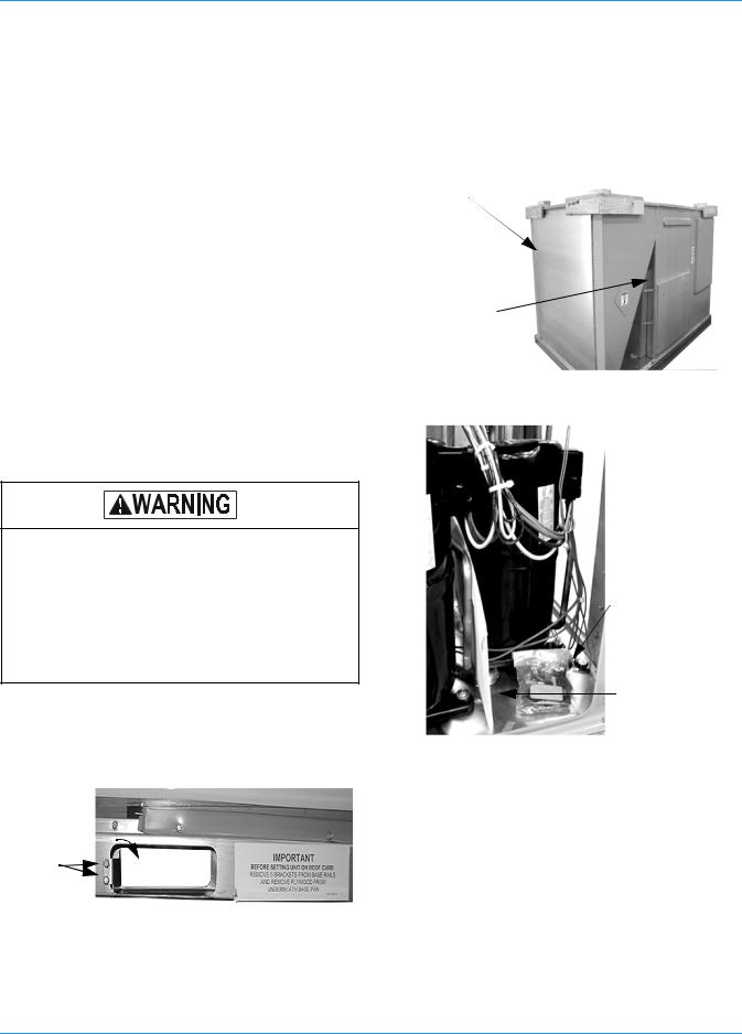
1.Remove the two screws holding the brackets in the front, rear and compressor side fork-lift slots.
2.Turn each bracket toward the ground and the protective plywood covering will drop to the ground.
3.Remove the condenser coil external protective covering prior to operation.
4.Remove the toolless doorknobs and instruction packet prior to installation.
Condenser
Coil External
Protective
Covering
Barometric Relief Hood in Shipping Location (if included)
FIGURE 2 - CONDENSER COVERING
Toolless
Doorknobs
Installation
Instruction
Packet
FIGURE 3 - COMPRESSOR SECTION
Bracket |
Turn down |
|
Screws |
||
|
FIGURE 1 - UNIT SHIPPING BRACKET
8 |
Unitary Products Group |
127878-YIM-B-0606
This product must be installed in strict compliance with the enclosed installation instructions and any applicable local, state and national codes including, but not limited to, building, electrical, and mechanical codes.
The furnace and its individual shut-off valve must be disconnected from the gas supply piping system during any pressure testing at pressures in excess of 1/2 PSIG.
Pressures greater than 1/2 PSIG will cause gas valve damage resulting in a hazardous condition. If it is subjected to a pressure greater than 1/2 PSIG, the gas valve must be replaced.
The furnace must be isolated from the gas supply piping system by closing its individual manual shut-off valve during any pressure testing of the gas supply piping system at test pressures equal to or less than 1/2 PSIG.
LIMITATIONS
These units must be installed in accordance with the following:
In U.S.A.:
1.National Electrical Code, ANSI/NFPA No. 70 - Latest Edition
2.National Fuel Gas Code, ANSI Z223.1 - Latest Edition
3.Gas-Fired Central Furnace Standard, ANSI Z21.47a. - Latest Edition
4.Local building codes, and
5.Local gas utility requirements
In Canada:
1.Canadian Electrical Code, CSA C22.1
2.Installation Codes, CSA - B149.1.
3.Local plumbing and waste water codes, and
4.Other applicable local codes.
Refer to Tables 1 & 2 for unit application data.
After installation, gas fired units must be adjusted to obtain a temperature rise within the range specified on the unit rating plate.
If components are to be added to a unit to meet local codes, they are to be installed at the dealer’s and/or customer’s expense.
Size of unit for proposed installation should be based on heat loss/heat gain calculation made according to the methods of Air Conditioning Contractors of America (ACCA).
This furnace is not to be used for temporary heating of buildings or structures under construction.
Unitary Products Group |
9 |
127878-YIM-B-0606
|
“Simplicity”™ Control Board |
|
|
Terminal Block |
w/ Screw Connector for T-stat |
Disconnect Location |
Filter Access |
for Hi-Voltage |
Wiring and Network |
(Optional Disconnect Switch) |
(2” Filters) |
Connection |
Connection |
|
|
Second model nameplate inside hinged access panel 
Dual stage cooling for maximum comfort
Compressor #2 Access (High-Eff  Compressor w/ crankcase heater)
Base Rails w/ Forklift Slots (3
Sides) & Lifting Holes
Roof curbs in eightand |
|
|
|
|
Slide-Out Drain |
|
|
|
|
||
fourteen-inch heights. |
|
|
|
|
|
|
|
|
|
Pan w/ Steel 3/4” |
|
Roof curbs for transition- |
|
|
|
|
|
|
|
|
|
NPT, Female |
|
ing fromSunline footprint |
|
|
|
|
|
|
|
|
|
Connection |
|
Tool-less |
|
|
|
||
to the DM/DH/DR Series |
|
|
|
|
|
door latch |
|
Side entry power |
|
||
footprint are also avail- |
|
Compressor #1 Access (High-Eff |
|||
|
|
and control wiring |
|||
able (field-installed |
|
|
Compressor w/ crankcase heater) |
||
|
|
knockouts |
|||
accessory) |
|
|
|
||
|
|
|
|
|
|
|
|
|
|
|
|
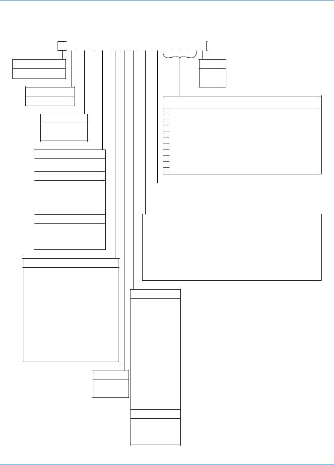
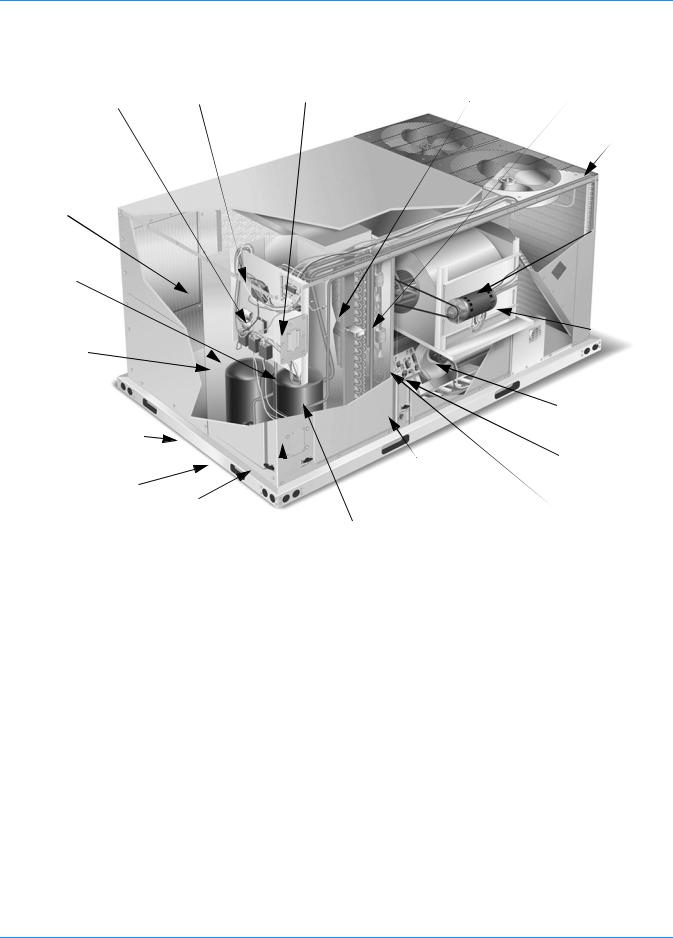
FIGURE 4 - PREDATOR MagnaDRY™ DR090 & 120 COMPONENT LOCATION
Filter-Drier (Solid Core)
Condenser
Section
Belt-Drive
Blower Motor
Slide-out motor and blower assembly for ease of adjustment and service
 Power Ventor Motor
Two-stage gas heat-  ing to maintain warm, comfortable temperature
Intelligent control board for safe and efficient operation
10 |
Unitary Products Group |
127878-YIM-B-0606
|
Simplicity™ Control |
Disconnect |
Filter access |
|
|
board w/screw |
|||
Second model |
location (optional |
(2" throw-away) |
||
connectors for T-stat |
||||
disconnect switch) |
|
|||
nameplate inside |
Filter drier (solid core) |
|||
|
||||
wiring and Network |
|
|||
hinged access panel |
|
|
||
Connection |
|
|
||
|
|
|
||
|
|
|
Condenser Section |
|
Dual stage cooling |
|
|
Belt-drive blower |
|
for maximum |
|
|
||
|
|
motor |
||
comfort |
|
|
||
|
|
|
||
|
|
|
Slide out motor |
|
Compressor #2 |
|
|
and blower |
|
|
|
assembly for easy |
||
access |
|
|
||
|
|
adjustment and |
||
(high-efficiency |
|
|
||
|
|
service |
||
compressor w/ |
|
|
||
|
|
|
||
crankcase heater) |
|
|
Power ventor |
|
|
|
|
||
|
|
|
motor |
Base rails w/ forklift slots
(three sides)
and lifting  holes
holes
Roof curbs in eight-and fourteen-inch heights.
Roof curbs for transitioning from York Sunline TM footprint to the DM/DH/DJ Series footprint are available (field-installed accessory)
Tool-less door latch
Side entry power and control wiring knockouts
Slide-out drain pan with brass ¾" NPT, female connection
Compressor #1 access (high-efficiency compressor w/crankcase heater)
20-gauge aluminized steel tubular heat exchanger for long life (stainless steel option)
Two-stage gas heating to maintain warm, comfortable temperature
Intelligent control board for safe and efficient operation
FIGURE 5 - PREDATOR MagnaDRY™ DR150 COMPONENT LOCATION
TABLE 1: UNIT VOLTAGE LIMITATIONS
Power Rating* |
Minimum |
Maximum |
208/230-3-60 |
187 |
252 |
460-3-60 |
432 |
504 |
575-3-60 |
540 |
630 |
*. Utilization range “A” in accordance with ARI Standard 110.
TABLE 2: UNIT TEMPERATURE LIMITATIONS
Temperature |
Min. |
Max. |
|
|
|
|
|
Wet Bulb Temperature (°F) of Air on |
57 |
72 |
|
Evaporator Coil |
|||
|
|
||
|
|
|
|
Dry Bulb Temperature (°F) of Air on |
0* |
125 |
|
Condenser Coil |
|||
|
|
||
|
|
|
*. A low ambient accessory is available for operation down to -20°F.
LOCATION
Use the following guidelines to select a suitable location for these units:
1.Unit is designed for outdoor installation only.
2.Condenser coils must have an unlimited supply of air. Where a choice of location is possible, position the unit on either north or east side of building.
3.Suitable for mounting on roof curb.
4.For ground level installation, use a level concrete slab with a minimum thickness of 4 inches. The length and width should be at least 6 inches greater than the unit base rails. Do not tie slab to the building foundation.
5.Roof structures must be able to support the weight of the unit and its options/accessories. Unit must be installed on a solid, level roof curb or appropriate angle iron frame.
6.Maintain level tolerance to 1/2” across the entire width and length of unit.
Unitary Products Group |
11 |
127878-YIM-B-0606
Excessive exposure of this furnace to contaminated combustion air may result in equipment damage or personal injury. Typical contaminates include: permanent wave solution, chlorinated waxes and cleaners, chlorine based swimming pool chemicals, water softening chemicals, carbon tetrachloride, Halogen type refrigerants, cleaning solvents (e.g. perchloroethylene), printing inks, paint removers, varnishes, hydrochloric acid, cements and glues, antistatic fabric softeners for clothes dryers, masonry acid washing materials.
|
|
FRONT |
LEFT |
B |
C |
|
A
RIGGING AND HANDLING
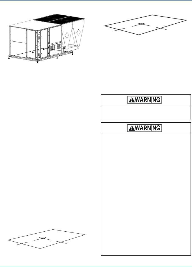
Exercise care when moving the unit. Do not remove any packaging until the unit is near the place of installation. Rig the unit by attaching chain or cable slings to the lifting holes provided in the base rails. Spreader bars, whose length exceeds the largest dimension across the unit, MUST be used across the top of the unit.
If a unit is to be installed on a roof curb other than a YORK roof curb, gasketing must be applied to all surfaces that come in contact with the unit underside.
Before lifting, make sure the unit weight is distributed equally on the rigging cables so it will lift evenly.
Units may be moved or lifted with a forklift. Slotted openings in the base rails are provided for this purpose.
LENGTH OF FORKS MUST BE A MINIMUM OF 60 INCHES.
All panels must be secured in place when the unit is lifted.
The condenser coils should be protected from rigging cable damage with plywood or other suitable material.
D
FIGURE 6 - DR090 & 120 UNITS 4 POINT LOAD
FRONT
C
LEFT |
B |
A
D
FIGURE 7 - DR150 UNIT 4 POINT LOAD
|
|
FRONT |
|
LEFT |
D |
|
C |
|
A |
B |
|
|
|
|
|
|
E |
F
FIGURE 8 - DR090 & 120 UNITS 6 POINT LOAD
12 |
Unitary Products Group |
127878-YIM-B-0606
|
|
|
|
|
|
|
|
|
|
|
FRONT |
|
|
|
|
|
|
|
|
|
|
|
|
|
|
|
|
|
|
|
|
|
|
|
|
|
|
|
|
|
|
|
|
|
|
|
|
|
|
|
|
|
|
|
|
|
|
|
D |
|
|
||
|
LEFT |
|
|
|
|
C |
|
E |
|
|
|||||
A |
|
B |
|
|
|
|
|
|
|||||||
|
|
|
|
|
|
|
|
|
|
|
|
|
|
||
|
|
|
|
|
|
|
|
|
|
|
|
||||
|
|
|
|
F |
|
|
|
|
|
|
|
|
|||
FIGURE 9 - DR150 UNIT 6 POINT LOAD |
|
|
|||||||||||||
TABLE 3: UNIT WEIGHTS |
|
|
|
|
|
|
|
|
|||||||
Model |
Shipping Weight* (lb.) |
|
Operating Weight* (lb.) |
||||||||||||
DR090 |
1163 |
|
|
1148 |
|
|
|||||||||
DR120 |
1277 |
|
|
1262 |
|
|
|||||||||
|
|
|
|
|
|
|
|
|
|
|
|
|
|
|
|
DR150 |
1560 |
|
|
1545 |
|
|
|||||||||
|
|
|
|
|
|
|
|
|
|
|
|
|
|
|
|
w/Econ. |
85 |
|
|
84 |
|
|
|
||||||||
|
|
|
|
|
|
|
|
|
|
|
|
|
|
|
|
w/ PE |
150 |
|
|
148 |
|
|
|||||||||
|
|
|
|
|
|
|
|
|
|
|
|
|
|
|
|
w/Elec. Heat |
49 |
|
|
49 |
|
|
|
||||||||
|
|
|
|
|
|
|
|
|
|
|
|
|
|
|
|
w/Gas Heat† |
110 |
|
|
110 |
|
|
|||||||||
*. 54 kW heater. |
|
|
|
|
|
|
|
|
|||||||
†. 8 Tube Heat Exchanger. |
|
|
|
|
|
|
|
|
|||||||
TABLE 4: 4 POINT LOAD WEIGHT |
|
|
|||||||||||||
|
Model |
|
|
|
|
|
|
Location (lbs.)* |
|
|
|||||
|
|
|
|
A |
|
B |
|
|
C |
|
D |
||||
|
|
|
|
|
|
|
|
|
|
|
|
|
|
|
|
|
DR090 |
|
250 |
|
|
|
215 |
|
|
309 |
|
|
374 |
|
|
|
DR120 |
|
276 |
|
|
|
237 |
|
|
341 |
|
|
408 |
|
|
|
|
|
|
|
|
|
|
|
|
|
|
|
|
|
|
|
DR150 |
|
293 |
|
|
|
370 |
|
|
479 |
|
|
393 |
|
|
*. Weights include largest gas heat option.
TABLE 5: 6 POINT LOAD WEIGHT
Model |
|
|
Location (lbs.)* |
|
|
|
|
A |
B |
C |
D |
E |
F |
|
|
|
|
|
|
|
DR090 |
171 |
154 |
139 |
201 |
225 |
258 |
DR120 |
188 |
170 |
154 |
220 |
248 |
282 |
|
|
|
|
|
|
|
DR150 |
191 |
217 |
253 |
329 |
286 |
260 |
*. Weights include largest gas heat option.
(090) 38" |
(090) 23" |
47-1/2" |
25-1/2" |
FRO NT
LEFT
FIGURE 10 - UNIT CENTER OF GRAVITY (DR090, 120)
60" 25-½"
FRONT
LEFT
FIGURE 11 - UNIT CENTER OF GRAVITY - DR150 CLEARANCES
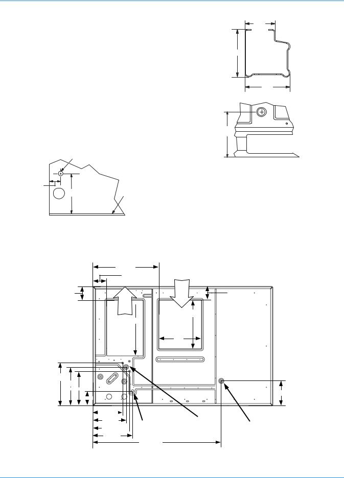
All units require particular clearances for proper operation and service. Installer must make provisions for adequate combustion and ventilation air in accordance with section 5.3 of Air for Combustion and Ventilation of the National Fuel Gas Code, ANSI Z223.1 – Latest Edition (in U.S.A.), or Sections 7.2, 7.3, or 7.4 of Gas Installation Codes, CSA-B149.1 (in Canada) - Latest Edition, and/or applicable provisions of the local building codes. Refer to Table 6 for clearances required for combustible construction, servicing, and proper unit operation.
Do not permit overhanging structures or shrubs to obstruct condenser air discharge outlet, combustion air inlet or vent outlets.
Excessive exposure to contaminated combustion air will result in safety and performance related problems. To maintain combustion air quality, the recommended source of combustion air is the outdoor air supply. The outdoor air supplied for combustion should be free from contaminants due to chemical exposure that may be present from the following sources.
•Commercial buildings
•Indoor pools
•Laundry rooms
•Hobby or craft rooms
•Chemical storage areas
The following substances should be avoided to maintain outdoor combustion air quality.
•Permanent wave solutions
•Chlorinated waxes and cleaners
•Chlorine based swimming pool cleaners
•Water softening chemicals
•De-icing salts or chemicals
•Carbon tetrachloride
•Halogen type refrigerants
•Cleaning solvents (such as perchloroethylene)
•Printing inks, paint removers, varnishes, etc.
•Hydrochloric acid
•Cements and glues
•Anti-static fabric softeners for clothes dryers
•Masonry acid washing materials
Unitary Products Group |
13 |

127878-YIM-B-0606
|
30-11/32 |
|
See Detail |
|
|
|
|
50-3/4 |
Power |
Control |
A |
|
|
||
|
Entry |
|
|
|
Entry |
|
|
|
Ø 7/8 |
|
|
|
Ø 2-1/2 |
|
|
|
|
|
4-1/4 |
|
|
Power |
|
|
|
|
|
Entry |
|
|
|
|
|
Ø 2-1/2 |
|
|
|
|
|
|
|
11-1/2 |
|
|
|
Convenience |
|
|
|
|
|
Power |
|
|
|
|
|
Outlet |
|
For Baserail |
|
|
|
Entry |
|
|
|
|
|
Ø 7/8 |
FRONT |
Dimensions |
|
|
17-3/16 |
|
See Detail B |
|
|
30-3/16 |
|
For Drain |
|
|
|
|
|
|
||
59 |
24-3/16 |
6-3/16 |
Dimensions |
|
|
See Detail C |
|
||||
LEFT |
|
|
|
|
|
|
|
27 |
89 |
|
|
|
|
|
|
||
FIGURE 12 - DR090 & 120 UNIT DIMENSIONS
|
|
|
|
|
|
|
119-7/16 |
|
|
|
|
|
|
|
|
|
||||||||
|
|
|
|
|
|
|
|
|
|
|
|
|
|
|
|
|
|
|
|
|
|
|
||
|
|
|
|
|
|
|
|
|
|
|
|
|
|
|
|
|
|
|
|
|
|
|||
|
|
|
|
|
|
|
|
|
|
|
|
|
|
|
|
|
|
|
|
|
For Gas Pipe Entry |
|
||
|
|
|
|
|
|
|
|
|
|
|
|
|
|
|
|
|
|
|
|
|
see DETAIL A |
|
||
|
|
|
|
|
|
|
|
|
|
|
|
|
|
|
|
|
|
Convenience |
|
|
|
|
||
|
|
|
|
|
|
|
|
|
|
|
Power |
|
Outlet |
|
|
|
|
|||||||
|
|
|
|
|
|
|
|
|
|
|
|
|
|
|
|
|
|
|
||||||
|
|
30-11/32 |
|
|
|
|
|
|
|
|
|
|
|
|
|
|
||||||||
|
|
|
|
|
|
|
Entry |
|
Convenience |
|
|
|
|
|||||||||||
|
|
|
|
|
|
2-1/2 |
|
|
|
|
|
|
|
|||||||||||
4-1/4 |
|
|
|
|
|
|
|
Outlet Power |
|
|
|
|
||||||||||||
|
|
|
|
|
|
|
|
|
|
|
|
|
|
|
|
|
|
|
|
|||||
|
|
|
|
|
|
|
|
|
|
|
Control |
|
Entry 7/8 |
|
|
|
|
|||||||
|
|
|
|
|
|
|
|
|
|
|
Entry |
|
|
|
|
|
|
|
|
|||||
50-3/4 |
|
|
|
|
|
7/8 |
|
|
|
|
|
|
FRONT |
11- |
1/2 |
|||||||||
|
|
|
|
|
|
|
|
|
|
|
For Baserail |
|||||||||||||
|
|
|
|
|
|
|
|
|
|
|
|
|
|
|
|
|
|
|
|
|||||
|
|
|
|
|
|
|
|
|
|
|
|
|
|
|
|
|
|
|
|
|||||
|
|
|
|
|
|
|
|
|
|
|
|
|
|
|
|
|
|
|
|
|||||
|
|
|
|
|
|
30-3/16 |
|
|
|
|
|
|
|
|
|
|
|
|
||||||
|
|
|
|
|
|
|
|
|
|
|
|
|
|
|
|
|
|
|
Dimensions |
|||||
|
|
|
|
|
|
|
|
|
17-3/16 |
|
|
|
|
|
|
|
|
see |
||||||
|
|
|
|
|
|
|
24-3/16 |
|
|
|
|
|
|
|
|
|
|
|
DETAIL B |
|||||
|
|
|
59 |
|
|
|
|
|
|
|
|
|
|
|
|
|
|
|||||||
|
|
|
|
|
|
|
|
6-3/16 |
|
|
|
89 |
|
|||||||||||
|
|
|
|
|
|
|
|
|
|
|
|
|
|
|
|
|
|
|
||||||
LEFT |
|
|
|
|
|
|
|
|
|
|
|
|
|
27 |
|
For Drain Dimensions |
||||||||
|
|
|
|
|
|
|
|
|
|
|
|
|
||||||||||||
|
|
|
|
|
|
|
|
|
|
|
|
|
|
|
|
|
|
|
||||||
|
|
|
|
|
|
|
|
|
|
|
|
|
|
|
|
|
||||||||
|
|
|
|
|
|
|
|
|
|
|
|
|
|
|
|
|
|
|
|
see DETAIL C |
|
|
|
|
FIGURE 13 - DR150 UNIT DIMENSIONS
14 |
Unitary Products Group |
127878-YIM-B-0606
TABLE 6: |
UNIT CLEARANCES |
|
||
Top* |
|
72” |
Right |
12” |
Front† |
|
36” |
Left |
36” |
Rear‡ |
|
36” |
Bottom** |
0” |
*. Units must be installed outdoors. Overhanging structure or shrubs should not obstruct condenser air discharge outlet.
†.The products of combustion must not be allowed to accumulate within a confined space and re-circulate.
‡.To remove the slide-out drain pan, a rear clearance of sixty inches is required. If space is unavailable, the drain pan can be removed through the front by separating the corner wall.
**. Units may be installed on combustible floors made from wood or class A, B or C roof covering materials.
DETAIL A |
GasPipeInlet |
|
5-1/4 |
|
Base |
|
17-13/16 |
|
|
Pan |
|
|
|
ViewofWalAcrossfromCoil
NOTE: A one-inch clearance must be provided between any combustible material and the supply ductwork for a distance of 3 feet from the unit.
32-11/16
6-13/16
6-13/16
Return 
Air
LEFT
27-1/2
 18
18 
21-3/16
19-3/16
17-3/16
7-1/8
14-23/32 |
FRONT |
16-3/8
Bottom 18-1/16  Condensate
Drain
19-5/8
63-1/2
DETAIL B |
2-3/8 |
|
3-3/4 |
3-9/16
DETAIL C
5-3/8
NOTE: If the unit includes gas heating, locate the unit so the flue exhaust is at least:
•Three (3) feet above any forced air inlet located within 10 horizontal feet (excluding those integral to the unit).
•Four (4) feet below, four (4) horizontal feet from, or one
(1) foot above any door or gravity air inlet into the building.
•Four (4) feet from electric meters, gas meters, regulators, and relief equipment.
.
Supply
Air
6-13/16
24
21
12-5/16
Bottom |
Bottom |
|
Power, Control and |
||
Gas Supply Entry |
||
Convenience Outlet |
||
|
||
Wiring Entries |
|
FIGURE 14 - BOTTOM DUCT OPENINGS (FROM ABOVE)
Unitary Products Group |
15 |
127878-YIM-B-0606
Dot Plugs |
|
18-1/4 |
|
|
|
||
|
|
||
|
|
|
|
Return
Air
Supply
Air
18-1/4
|
2-31/32 |
5-5/32 |
C |
|
|
|
31-11/16 |
FIGURE 15 - DR090 & 120 REAR DUCT DIMENSIONS
A
B
Dot
Plugs  18-1/4
Return |
|
Air |
28-1/4 |
|
Supply
Air
18-1/4
18-1/16
2-31/32
28-1/4
5-5/32 |
|
31-11/16 |
|
FIGURE 16 - DR150 REAR DUCT DIMENSIONS
16 |
Unitary Products Group |
127878-YIM-B-0606
DUCTWORK
Ductwork should be designed and sized according to the methods in Manual D of the Air Conditioning Contractors of America (ACCA) or as recommended by any other recognized authority such as ASHRAE or SMACNA.
A closed return duct system should be used. This will not preclude use of economizers or outdoor fresh air intake. The supply and return air duct connections at the unit should be made with flexible joints to minimize noise.
The supply and return air duct systems should be designed for the CFM and static pressure requirements of the job. They should NOT be sized to match the dimensions of the duct connections on the unit.
Refer to Figure 14 for bottom air duct openings. Refer to Figure 15 and 16 for rear air duct openings.
DUCT COVERS
Units are shipped with the side duct openings covered and a covering over the bottom of the unit. For bottom duct application, no duct cover changes are necessary. For side duct application, remove the side duct covers and install over the bottom duct openings. The panels removed from the side duct connections are designed to be reused by securing each panel to its respective downflow opening. But keep in mind that the supply panel is installed with the painted surface UP, facing the heat exchanger, while the return panel is installed with the painted surface DOWN, facing the downflow duct opening. The supply panel is secured with the bracket (already in place from the factory) and two screws. It’s a snug fit for the panel when sliding it between the heat exchanger and unit bottom, but there is room. The return panel is secured with four screws.
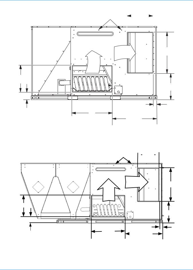
|
RIGHT |
80-5/8 |
INSULATEDDECKUNDER |
|
|
|
CONDENSERSECTION |
20 |
|
SUPPLY
20 6
RETURN
2TYP.
30
50-1/2 |
INSULATEDDECKUNDER |
|
COMPRESSORSECTION |
FRONT
8or14
FIGURE 17 - PREDATOR® ROOF CURB DIMENSIONS
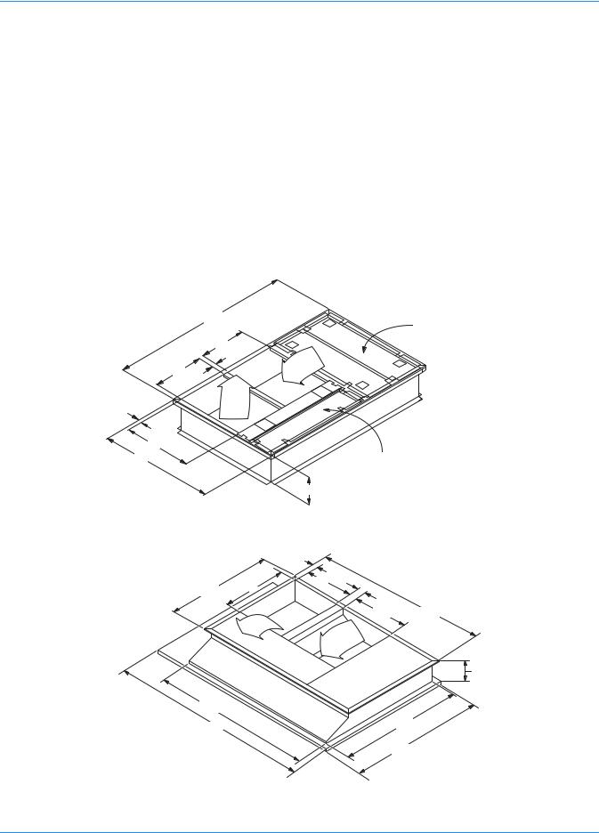
2TYP
23 4
50-1/2 30-1/2
26 80-5/8
RETURN
SUPPLY
10
76-5/8 |
|
94 |
59-1/4 |
|
|
FRONT |
64-1/4 RIGHT |
FIGURE 18 - SUNLINE™ TO PREDATOR® TRANSITION ROOF CURBS
Unitary Products Group |
17 |
127878-YIM-B-0606
When fastening ductwork to side duct flanges on unit, insert screws through duct flanges only. DO NOT insert screws through casing. Outdoor ductwork must be insulated and water-proofed.
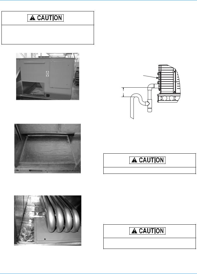
FIGURE 19 - SIDE PANELS WITH HOLE PLUGS
Note orientation. Panel is “insulation” side up.
FIGURE 20 - RETURN DOWNFLOW PLENUM WITH PANEL
FIGURE 21 - DISCHARGE PANEL IN PLACE
CONDENSATE DRAIN
The side condensate drain is reversible and maybe re-ori- ented to the rear of the cabinet to facilitate condensate piping. A condensate drain connection is available through the base pan for piping inside the roof curb. Trap the connection per Figure 22. The trap and drain lines should be protected from freezing.
Plumbing must conform to local codes. Use a sealing compound on male pipe threads. Install condensate drain line from the 3/4 inch NPT female connection on the unit to an open drain.
OPTIONALCOIL
GUARD
3"Minimum
FIGURE 22 - CONDENSATE DRAIN
COMPRESSORS
The compressors are mounted on elastomer insulators. The mounting bolts have been fully tightened for shipping.
Do not loosen the compressor mounting bolts.
FILTERS
Two-inch filters are supplied with each unit. One-inch filters may be used with no modification to the filter racks. Filters must always be installed ahead of evaporator coil and must be kept clean or replaced with same size and type. Dirty filters reduce the capacity of the unit and result in frosted coils or safety shutdown. All units use four (4) 20”x25”x2” filters. The unit should not be operated without filters properly installed.
Make sure that panel latches are properly positioned on the unit to maintain an airtight seal.
18 |
Unitary Products Group |
127878-YIM-B-0606
THERMOSTAT WIRING
The thermostat should be located on an inside wall approximately 56 inch above the floor where it will not be subject to drafts, sun exposure or heat from electrical fixtures or appliances. Follow the manufacturer's instructions enclosed with thermostat for general installation procedure. Seven (7) colorcoded, insulated wires should be used to connect the thermostat to the unit. Refer to Table 7 for control wire sizing and maximum length.
TABLE 7: CONTROL WIRE SIZES
Wire Size |
Maximum Length* |
18 AWG |
150 Feet |
|
|
*. From the unit to the thermostat and back to the unit.
POWER AND CONTROL WIRING
Field wiring to the unit, fuses, and disconnects must conform to provisions of National Electrical Code (NEC), ANSI/NFPA No. 70 – Latest Edition (in U.S.A.), current Canadian Electrical Code C221, and/or local ordinances. The unit must be electrically grounded in accordance with NEC and CEC as specified above and/or local codes.
Voltage tolerances which must be maintained at the compressor terminals during starting and running conditions are indicated on the unit Rating Plate and Table 1.
The internal wiring harnesses furnished with this unit are an integral part of the design certified unit. Field alteration to comply with electrical codes should not be required. If any of the wire supplied with the unit must be replaced, replacement wire must be of the type shown on the wiring diagram and the same minimum gauge as the replaced wire.
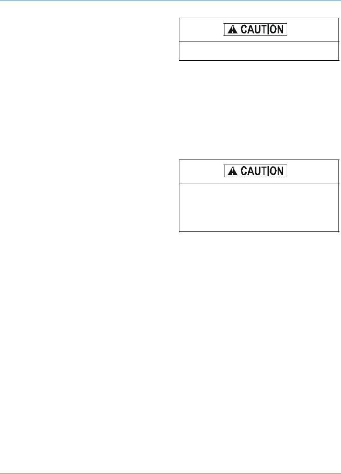
A disconnect must be utilized for these units. Factory installed disconnects are available. If installing a disconnect
(field supplied or York International® supplied accessory), refer to Figures 4 and 5 for the recommended mounting location.
Avoid damage to internal components if drilling holes for disconnect mounting.
NOTE: Since not all local codes allow the mounting of a disconnect on the unit, please confirm compliance with local code before mounting a disconnect on the unit.
Electrical line must be sized properly to carry the load. USE COPPER CONDUCTORS ONLY. Each unit must be wired with a separate branch circuit fed directly from the meter panel and properly fused.
Refer to Figure 23 for typical field wiring and to the appropriate unit wiring diagram mounted inside control doors for control circuit and power wiring information.
When connecting electrical power and control wiring to the unit, water-proof connectors must be used so that water or moisture cannot be drawn into the unit during normal operation. The above water-proofing conditions will also apply when installing a field supplied disconnect switch.
POWER WIRING DETAIL
Units are factory wired for the voltage shown on the unit nameplate. Refer to Electrical Data Tables 8 to 13 to size power wiring, fuses, and disconnect switch.
Power wiring is brought into the unit through the side of the unit or the basepan inside the curb.
Unitary Products Group |
19 |
127878-YIM-B-0606
THERMOSTAT 1 |
|
|
( RCB ) |
|
|
|
|
|||
TERMINALS |
|
|
REHEAT |
|
|
|
|
|||
|
|
|
|
|
|
CONTROL BOARD |
|
|
|
|
RC |
|
|
|
|
|
|
|
|||
RH |
|
|
R |
|
|
|
|
|||
Y1 |
|
|
Y1 |
|
|
|
|
|||
Y2 |
|
|
Y2 |
|
|
|
|
|||
W1 |
|
|
W1 |
|
|
|
|
|||
W2 |
|
|
W2 |
|
|
|
|
|||
G |
|
|
G |
|
|
|
|
|||
C |
|
|
C |
|
|
|
|
|||
X1 |
|
|
OCC |
|
|
|
|
|||
X3 |
|
|
TERMINAL BLOCK |
|
|
|
||||
2 |
|
|
|
|
||||||
|
|
RH |
|
|
|
|||||
|
|
|
|
|
|
|
|
|
||
X4 |
|
|
|
|
|
|
||||
|
|
|
|
|
|
|
||||
A1 |
|
|
HUM |
1 |
|
|
|
|||
|
|
|
|
|
|
|
|
|
||
A2 |
|
|
HUM |
2 |
DEHUMIDISTAT3 |
|
|
|||
T |
|
|
|
|
|
3 |
|
|
|
|
T |
|
|
|
|
|
|
4 |
|
|
|
|
|
|
|
|
|
|
|
|
||
|
|
|
|
|
|
|||||
|
|
|
|
|
|
|
|
|
|
|
TO REMOTE SENSOR |
|
|
|
|
|
|||||
2ET04701324 IF USED |
|
|
|
|
|
|||||
1 Electronic programmable Thermostat 2ET0770010024 |
|
|
|
|
||||||
( includes subbase). |
|
|
|
|
|
|
|
|||
2 Terminals A1 and A2 provide a relay output to close the |
|
|
|
|
||||||
outdoor economizer dampers when the thermostat |
|
|
|
|
||||||
switches to the set-back position. |
|
|
|
|
|
|||||
3 Dehumidistat closes on rise in humidity. |
|
|
|
|
||||||
|
|
|
|
|
|
TYPICAL |
|
|
|
|
|
|
|
|
|
|
THERMOSTAT |
|
|
|
|
|
|
|
|
|
|
RC |
R |
|
|
|
|
|
|
|
|
|
RH |
Y1 |
|
|
|
|
|
|
|
|
|
Y1 |
Y2 |
( RCB ) |
||
|
|
|
|
|
|
Y2 |
G |
REHEAT |
||
|
|
|
|
|
|
G |
W1 |
CONTROL |
||
|
|
|
|
|
|
BOARD |
||||
|
|
|
|
|
|
|
|
|||
|
|
|
|
|
|
W1 |
W2 |
|
TERMINAL |
|
|
|
|
|
|
|
W2 |
OCC |
|
BLOCK |
|
|
|
|
|
|
|
C |
C |
|
RH |
|
|
|
|
|
|
|
|
|
|
||
|
|
|
|
|
|
|
|
1 |
|
|
|
|
|
|
|
|
|
|
DEHUMIDISTAT1 |
||
|
|
|
|
|
|
|
|
2 |
||
|
|
|
|
|
|
|
|
|
||
3
4
HUM
1Dehumidistat closes on rise in humidity.
FIGURE 23 -TYPICAL LOW VOLTAGE FIELD WIRING
20 |
Unitary Products Group |
127878-YIM-B-0606
TERMINAL BLOCK TB1
FACTORY OR FIELD
SUPPLIED DISCONNECT
GROUND
LUG
THREE
PHASE
POWER
SUPPLY
FIGURE 24 - FIELD WIRING DISCONNECT - COOLING UNIT WITH/WITHOUT ELECTRIC HEAT
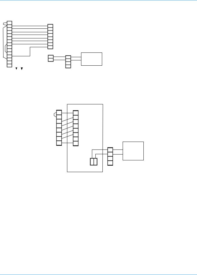
CONTACTOR 1M
T1 |
T2 |
T3 |
L1 |
L2 |
L3 |
|
|
FACTORY OR FIELD |
GROUND |
|
SUPPLIED DISCONNECT |
LUG |
|
|
THREE
PHASE
POWER
SUPPLY
FIGURE 25 - FIELD WIRING DISCONNECT-COOLING UNIT WITH GAS HEAT
Unitary Products Group |
21 |

127878-YIM-B-0606
TABLE 8: ELECTRICAL DATA - DR090 WITHOUT POWERED CONVENIENCE OUTLET
|
|
|
|
Supply |
Pwr |
Pwr |
|
|
|
Min. Circuit |
MCA |
Max |
Max Fuse Size |
|||||
|
|
|
OD Fan |
|
|
|
w/Power |
Fuse* |
w/Power |
|||||||||
|
Compressors |
Blower |
Exh |
Conv |
Electric Heater |
Actual |
Heater |
Ampacity |
||||||||||
Voltage |
|
|
Motors |
Motor FLA |
Motor |
Outlet |
(Amps) |
Exhaust |
Size |
Exhaust |
||||||||
|
|
|
|
|
|
|
|
Model No. |
KW |
Amps |
|
|
(Amps) |
(Amps) |
(Amps) |
|||
|
RLA |
LRA |
FLA |
1.5 |
2 |
FLA |
FLA |
|
|
|
1.5 |
2 |
1.5 |
2 |
1.5 |
2 |
1.5 |
2 |
|
ea. |
ea. |
ea. |
HP |
HP |
|
|
|
HP |
HP |
HP |
HP |
HP |
HP |
HP |
HP |
||
|
|
|
|
|
|
|||||||||||||
|
|
|
|
|
|
|
|
None |
-- |
-- |
38.7 |
40.7 |
44.2 |
46.2 |
50 |
50 |
50 |
50 |
|
|
|
|
|
|
|
|
2TP04520925 |
6.8 |
18.9 |
38.7 |
40.7 |
44.2 |
46.2 |
50 |
50 |
50 |
50 |
208 |
13.1 |
110.0 |
1.5 |
6.2 |
8.2 |
5.5 |
0.0 |
2TP04521825 |
13.5 |
37.5 |
54.6 |
57.1 |
61.5 |
64.0 |
60 |
60 |
70 |
70 |
|
|
|
|
|
|
|
|
2TP04522425 |
18 |
50.0 |
70.2 |
72.7 |
77.1 |
79.6 |
80 |
80 |
80 |
80 |
|
|
|
|
|
|
|
|
2TP04523625 |
25.5 |
70.8 |
96.2 |
98.7 |
103.1 |
105.6 |
100 |
100 |
110 |
110 |
|
|
|
|
|
|
|
|
None |
-- |
-- |
38.7 |
40.7 |
44.2 |
46.2 |
50 |
50 |
50 |
50 |
|
|
|
|
|
|
|
|
2TP04520925 |
9 |
21.7 |
38.7 |
40.7 |
44.2 |
46.2 |
50 |
50 |
50 |
50 |
230 |
13.1 |
110.0 |
1.5 |
6.2 |
8.2 |
5.5 |
0.0 |
2TP04521825 |
18 |
43.3 |
61.9 |
64.4 |
68.8 |
71.3 |
70 |
70 |
70 |
80 |
|
|
|
|
|
|
|
|
2TP04522425 |
24 |
57.7 |
79.9 |
82.4 |
86.8 |
89.3 |
80 |
90 |
90 |
90 |
|
|
|
|
|
|
|
|
2TP04523625 |
34 |
81.8 |
110.0 |
112.5 |
116.9 |
119.4 |
110 |
125 |
125 |
125 |
|
|
|
|
|
|
|
|
None |
-- |
-- |
19.8 |
20.8 |
22 |
23 |
25 |
25 |
25 |
25 |
|
|
|
|
|
|
|
|
2TP04520946 |
9 |
11.3 |
19.8 |
20.8 |
22 |
23 |
25 |
25 |
25 |
25 |
460 |
6.7 |
54.0 |
0.8 |
3.1 |
4.1 |
2.2 |
0.0 |
2TP04521846 |
18 |
22.6 |
30.9 |
32.2 |
33.7 |
34.9 |
35 |
35 |
35 |
35 |
|
|
|
|
|
|
|
|
2TP04522446 |
24 |
30.1 |
40 |
41.2 |
42.7 |
44 |
40 |
45 |
45 |
45 |
|
|
|
|
|
|
|
|
2TP04523646 |
34 |
42.7 |
55 |
56.2 |
57.7 |
59 |
60 |
60 |
60 |
60 |
|
|
|
|
|
|
|
|
None |
-- |
-- |
15.1 |
16.3 |
16.9 |
18.1 |
20 |
20 |
20 |
20 |
|
|
|
|
|
|
|
|
2TP04520958 |
9 |
9.0 |
15.1 |
16.3 |
16.9 |
18.1 |
20 |
20 |
20 |
20 |
575 |
5.1 |
44.0 |
0.6 |
2.4 |
3.6 |
1.8 |
0.0 |
2TP04521858 |
18 |
18.1 |
24.7 |
26.2 |
26.9 |
28.4 |
25 |
30 |
30 |
30 |
|
|
|
|
|
|
|
|
2TP04522458 |
24 |
24.1 |
31.9 |
33.4 |
34.1 |
35.6 |
35 |
35 |
35 |
40 |
|
|
|
|
|
|
|
|
2TP04523658 |
34 |
34.1 |
43.9 |
45.4 |
46.1 |
47.6 |
45 |
50 |
50 |
50 |
*Maximum HACR breaker of the same AMP size is applicable.
TABLE 9: ELECTRICAL DATA - DR090 WITH POWERED CONVENIENCE OUTLET
|
|
|
|
|
Supply |
Pwr |
Pwr |
|
|
|
Min. Circuit |
MCA |
Max |
Max Fuse Size |
|
|||||
|
|
|
|
OD Fan |
|
|
|
w/Power |
Fuse* |
w/Power |
|
|||||||||
|
|
Compressors |
Blower |
Exh |
Conv |
Electric Heater |
Actual |
Heater |
Ampacity |
|
||||||||||
|
Voltage |
|
|
Motors |
Motor FLA |
Motor |
Outlet |
(Amps) |
Exhaust |
Size |
Exhaust |
|
||||||||
|
|
|
|
|
|
|
|
|
Model No. |
KW |
Amps |
|
|
(Amps) |
(Amps) |
(Amps) |
|
|||
|
|
RLA |
LRA |
FLA |
1.5 |
2 |
FLA |
FLA |
|
|
|
1.5 |
2 |
1.5 |
2 |
1.5 |
2 |
1.5 |
2 |
|
|
|
ea. |
ea. |
ea. |
HP |
HP |
|
|
|
HP |
HP |
HP |
HP |
HP |
HP |
HP |
HP |
|
||
|
|
|
|
|
|
|
|
|||||||||||||
|
|
|
|
|
|
|
|
|
None |
-- |
-- |
48.7 |
50.7 |
54.2 |
56.2 |
60 |
60 |
60 |
60 |
|
|
|
|
|
|
|
|
|
|
2TP04520925 |
6.8 |
18.9 |
48.7 |
50.7 |
54.2 |
56.2 |
60 |
60 |
60 |
60 |
|
208 |
13.1 |
110.0 |
1.5 |
6.2 |
8.2 |
5.5 |
10.0 |
2TP04521825 |
13.5 |
37.5 |
67.1 |
69.6 |
74.0 |
76.5 |
70 |
70 |
80 |
80 |
|
|
|
|
|
|
|
|
|
|
|
2TP04522425 |
18 |
50.0 |
82.7 |
85.2 |
89.6 |
92.1 |
90 |
90 |
90 |
100 |
|
|
|
|
|
|
|
|
|
|
2TP04523625 |
25.5 |
70.8 |
108.7 |
111.2 |
115.6 |
118.1 |
110 |
125 |
125 |
125 |
|
|
|
|
|
|
|
|
|
|
None |
-- |
-- |
48.7 |
50.7 |
54.2 |
56.2 |
60 |
60 |
60 |
60 |
|
|
|
|
|
|
|
|
|
|
2TP04520925 |
9 |
21.7 |
48.7 |
50.7 |
54.2 |
56.7 |
60 |
60 |
60 |
60 |
|
230 |
13.1 |
110.0 |
1.5 |
6.2 |
8.2 |
5.5 |
10.0 |
2TP04521825 |
18 |
43.3 |
74.4 |
76.9 |
81.3 |
83.8 |
80 |
80 |
90 |
90 |
|
|
|
|
|
|
|
|
|
|
|
2TP04522425 |
24 |
57.7 |
92.4 |
94.9 |
99.3 |
101.8 |
100 |
100 |
100 |
110 |
|
|
|
|
|
|
|
|
|
|
2TP04523625 |
34 |
81.8 |
122.5 |
125.0 |
129.4 |
131.9 |
125 |
125 |
150 |
150 |
|
|
|
|
|
|
|
|
|
|
None |
-- |
-- |
24.8 |
25.8 |
27 |
28 |
30 |
30 |
30 |
30 |
|
|
|
|
|
|
|
|
|
|
2TP04520946 |
9 |
11.3 |
24.8 |
25.8 |
27 |
28 |
30 |
30 |
30 |
30 |
|
460 |
6.7 |
54.0 |
0.8 |
3.1 |
4.1 |
2.2 |
5.0 |
2TP04521846 |
18 |
22.6 |
37.2 |
38.4 |
39.9 |
41.2 |
40 |
40 |
40 |
45 |
|
|
|
|
|
|
|
|
|
|
|
2TP04522446 |
24 |
30.1 |
46.2 |
47.5 |
49 |
50.2 |
50 |
50 |
50 |
60 |
|
|
|
|
|
|
|
|
|
|
2TP04523646 |
34 |
42.7 |
61.2 |
62.5 |
64 |
65.2 |
70 |
70 |
70 |
70 |
|
|
|
|
|
|
|
|
|
|
None |
-- |
-- |
19.1 |
20.3 |
20.9 |
22.1 |
20 |
25 |
25 |
25 |
|
|
|
|
|
|
|
|
|
|
2TP04520958 |
9 |
9.0 |
19.1 |
20.3 |
21.1 |
22.6 |
20 |
25 |
25 |
25 |
|
575 |
5.1 |
44.0 |
0.6 |
2.4 |
3.6 |
1.8 |
4.0 |
2TP04521858 |
18 |
18.1 |
29.7 |
31.2 |
31.9 |
33.4 |
30 |
35 |
35 |
35 |
|
|
|
|
|
|
|
|
|
|
|
2TP04522458 |
24 |
24.1 |
36.9 |
38.4 |
39.1 |
40.6 |
40 |
40 |
40 |
45 |
|
|
|
|
|
|
|
|
|
|
2TP04523658 |
34 |
34.1 |
48.9 |
50.4 |
51.1 |
52.6 |
50 |
60 |
60 |
60 |
|
*Maximum HACR breaker of the same AMP size is applicable.
22 |
Unitary Products Group |
 Loading...