


J |
CHAMPION® |
SERIES |
|
SINGLE PACKAGE AIR CONDITIONERS |
|
|
GAS/ELECTRIC, AIR-COOLED |
|
INSTALLATION INSTRUCTION |
Supersedes: 035-18265-000-A-0801 |
035-18265-001-A-0202 |
MODELS D1NA018 THRU 048 AND MODEL D2NA060
1-1/2 THRU 5 TON
(10 SEER)
WARNING: If the information in this manual is not followed exactly, a fire or explosion may result causing property damage, personal injury or loss of life.
—Do not store or use gasoline or other flammable vapors and liquids in the vicinity of this or any other appliance.
—WHAT TO DO IF YOU SMELL GAS
Do not try to light any appliance.
Extinguish any open flames.
Do not touch any electrical switch; do not use any phone in your building.
Immediately call your gas supplier from a neighbor's phone. Follow the gas supplier's instructions.
If you cannot reach your gas supplier, call the fire department.
GENERAL
YORK Model D1NA and D2NA units are cooling/heating air conditioners designed for outdoor installation. Only gas piping, electric power and duct connections are required at the point of installation.
The gas-fired heaters have hot surface to pilot ignition. The tubular heat exchangers are aluminized steel.
This appliance is not to be used for temporary heating of buildings or structures under construction.
INSPECTION
As soon as a unit is received, it should be inspected for possible damage during transit. If damage is evident, the extent of the damage should be noted on the carrier's freight bill. A separate request for inspection by the carrier's agent should be made in writing. Refer to Form 50.15-NM for additional information.
REPLACEMENT PARTS
•Refer to Replacement Parts, Form 530.46-RP1Y, RP2Y, RP3Y, RP4Y and RP5Y for Key Replacement Parts.
All forms referenced in this instruction may be ordered from:
Standard Register
Norman, OK 73069
Toll Free: Tel. 877-318-9675/Fax. 877-379-7920
APPROVALS
Design certified by CGA and AGA listed as follows:
1.For use as a forced air furnace with cooling unit.
2.For outdoor installation only.
3.For installation directly on combustible flooring or, in U.S., on wood flooring or Class A; B; C roof covering material.
4.For installation on combustible material.
5.For use with natural gas and/or propane (LP) gas.
CAUTION
THIS PRODUCT MUST BE INSTALLED IN STRICT COMPLIANCE WITH
THE ENCLOSED INSTALLATION INSTRUCTIONS AND ANY APPLICABLE
LOCAL, STATE, AND NATIONAL CODES INCLUDING, BUT NOT LIMITED
TO, BUILDING, ELECTRICAL, AND MECHANICAL CODES.
WARNING
INCORRECT INSTALLATION MAY CREATE A CONDITION WHERE THE OPERATION OF THE PRODUCT COULD CAUSE PERSONAL INJURY O R PRO PERT Y DAM AG E.
Installer should pay particular attention to the words: NOTE, CAUTION and WARNING. Notes are intended to clarify or make the installation easier. Cautions are given to prevent equipment damage. Warnings are given to alert installer that personal injury and/or equipment damage may result if installation procedure is not handled properly.

035-18265-001-A-0202
TABLE OF CONTENTS
General............................................................................ |
|
|
|
|
|
|
|
|
1 |
|
|
|
|
|
|
|
|
|
|
|
|
|
|
TROUBLESHOOTING |
|
||||||||||||||||||
Inspection |
|
|
|
|
|
|
|
|
1 |
|
|
|
|
|
|
|
|
|
|
|
|
|
|
|
|||||||||||||||||||
|
|
|
|
|
|
|
|
|
|
Troubleshooting Chart |
|
|
|
15 |
|||||||||||||||||||||||||||||
Replacement Parts |
|
|
|
|
|
|
|
|
1 |
|
|
|
|
|
|||||||||||||||||||||||||||||
|
|
|
|
|
|
|
|
|
|
|
|
|
|
|
|
|
|
|
|
|
|
|
|
|
|
|
|
|
|
|
|
|
|||||||||||
Approvals......................................................................... |
|
|
|
|
|
|
|
|
1 |
|
|
|
|
|
|
|
|
|
|
|
|
|
|
|
|
|
|
TABLES |
|
|
|
|
|||||||||||
Nomenclature .................................................................. |
|
|
|
|
|
|
|
|
2 |
|
|
|
|
No. |
|
|
|
|
|
|
|
|
|
|
|
|
|
||||||||||||||||
|
|
|
|
|
|
|
|
|
|
|
|
|
|
|
|
|
|
|
|
|
|
|
|
|
|
|
|
|
|
|
Description |
|
|
|
|
||||||||
|
INSTALLATION |
|
|
|
|
|
Page |
|
|
|
|
|
|
|
|
|
|
|
|
|
|
|
|||||||||||||||||||||
Limitations........................................................................ |
|
|
|
|
|
|
|
|
3 |
|
|
1 |
|
|
|
|
Units Application Data |
|
|
|
3 |
||||||||||||||||||||||
Location |
|
|
|
|
|
|
|
|
3 |
|
|
|
|
|
|
|
|
|
|||||||||||||||||||||||||
|
|
|
|
|
|
|
|
|
|
2 |
|
|
|
|
Natural Gas Application Data |
5 |
|||||||||||||||||||||||||||
Rigging and Handling |
|
|
|
|
|
|
|
|
3 |
|
|
|
|
|
|
||||||||||||||||||||||||||||
|
|
|
|
|
|
|
|
|
|
3 |
|
|
|
|
LP Gas Application Data |
|
|
|
5 |
||||||||||||||||||||||||
Clearances ...................................................................... |
|
|
|
|
|
|
|
|
3 |
|
|
|
|
|
|
|
|
|
|||||||||||||||||||||||||
Ductwork.......................................................................... |
|
|
|
|
|
|
|
|
3 |
|
|
4 |
|
|
|
|
Natural Gas Pipe Sizing .............................. |
|
|
|
5 |
||||||||||||||||||||||
Roof Curb ........................................................................ |
|
|
|
|
|
|
|
|
4 |
|
|
5 |
|
|
|
|
LP Gas Pipe Sizing |
|
|
|
5 |
||||||||||||||||||||||
Filters |
|
|
|
|
|
|
|
|
4 |
|
|
|
|
|
|
|
|
|
|||||||||||||||||||||||||
|
|
|
|
|
|
|
|
|
|
6 |
|
|
|
|
Physical Data |
|
|
|
6 |
||||||||||||||||||||||||
Condensate Drain |
|
|
|
|
|
|
|
|
4 |
|
|
|
|
|
|
|
|
|
|||||||||||||||||||||||||
|
|
|
|
|
|
|
|
|
|
7 |
|
|
|
|
Unit Weights |
|
|
|
7 |
||||||||||||||||||||||||
Service Access ................................................................ |
|
|
|
|
|
|
|
|
4 |
|
|
|
|
|
|
|
|
|
|||||||||||||||||||||||||
Thermostat....................................................................... |
|
|
|
|
|
|
|
|
4 |
|
|
8 |
|
|
|
|
Electrical Data ............................................. |
|
|
|
7 |
||||||||||||||||||||||
Power and Control Wiring................................................ |
|
|
|
|
|
|
|
|
4 |
|
|
|
|
|
|
|
|
|
|
|
|
|
|
|
|
|
|
|
|
|
|
|
|
|
|||||||||
Compressors ................................................................... |
|
|
|
|
|
|
|
|
4 |
|
|
9 |
|
|
|
|
Gas Rate - Cubic Feet Per Hour |
11 |
|||||||||||||||||||||||||
Combustion Discharge |
|
|
|
|
|
|
|
|
5 |
|
|
|
|
|
|
||||||||||||||||||||||||||||
|
|
|
|
|
|
|
|
|
|
10 |
|
|
|
|
Superheat Charging Table, 018 |
13 |
|||||||||||||||||||||||||||
Gas Piping ....................................................................... |
|
|
|
|
|
|
|
|
5 |
|
|
|
|
|
|
||||||||||||||||||||||||||||
Gas Connection ............................................................... |
|
|
|
|
|
|
|
|
5 |
|
|
11 |
|
|
|
|
Superheat Charging Table, 024................... |
13 |
|||||||||||||||||||||||||
Flue Vent Hoods .............................................................. |
|
|
|
|
|
|
|
|
6 |
|
|
12 |
|
|
|
|
Superheat Charging Table, 030 |
13 |
|||||||||||||||||||||||||
|
|
|
|
|
|
|
|
|
|
|
|
|
|
|
|
|
|
|
|
|
|
|
|
|
|||||||||||||||||||
|
SEQUENCE OF OPERATION |
|
|
|
|
|
13 |
|
|
|
|
Superheat Charging Table, 036................... |
13 |
||||||||||||||||||||||||||||||
Heating ............................................................................ |
|
|
|
|
|
|
|
|
9 |
|
|
14 |
|
|
|
|
Superheat Charging Table, 042................... |
14 |
|||||||||||||||||||||||||
Cooling ............................................................................ |
|
|
|
|
|
|
|
|
9 |
|
|
15 |
|
|
|
|
Superheat Charging Table, 048 |
14 |
|||||||||||||||||||||||||
Circulating Fan |
|
|
|
|
|
|
|
|
9 |
|
|
|
|
|
|
||||||||||||||||||||||||||||
|
|
|
|
|
|
|
|
|
|
16 |
|
|
|
|
Superheat Charging Table, 060 |
14 |
|||||||||||||||||||||||||||
|
|
|
|
|
|
|
|
|
|
|
|
|
|
|
|
|
|
|
|
|
|
|
|
|
|||||||||||||||||||
|
START-UP |
|
|
|
|
|
|
|
|
|
|
|
|
|
|
|
|
|
|
|
|
|
|
|
|
|
|
|
|
|
FIGURES |
|
|
|
|
||||||||
Pre-start Check List ......................................................... |
|
|
|
|
|
|
|
|
9 |
|
|
|
|
|
|
|
|
|
|
|
|
|
|
|
|
|
|
|
|
|
|
||||||||||||
Operating Instructions...................................................... |
|
|
|
|
|
|
|
|
9 |
|
|
|
|
No. |
|
|
|
|
|
|
|
|
|
|
Description |
|
|
|
|
||||||||||||||
|
|
|
|
|
|
|
|
|
|
|
|
|
|
|
|
|
|
|
|
|
|
|
|
|
|
|
|
|
|||||||||||||||
To Turn Off Gas To Unit ................................................... |
|
|
|
|
|
|
|
|
9 |
|
|
Page |
|
|
|
|
|
|
|
|
|
|
|
|
|
|
|
||||||||||||||||
Post-Start Check List (Gas) ............................................. |
|
|
|
|
|
|
|
|
9 |
|
|
1 |
|
|
|
|
Field Wiring Diagram |
|
|
|
4 |
||||||||||||||||||||||
Manifold Gas Pressure Adjustment |
|
|
|
|
|
|
|
|
10 |
|
|
|
|
|
|
|
|
|
|||||||||||||||||||||||||
|
|
|
|
|
|
|
|
|
|
2 |
|
|
|
|
External Supply Connection |
5 |
|||||||||||||||||||||||||||
Burner Instructions |
|
|
|
|
|
|
|
|
10 |
|
|
|
|
|
|
||||||||||||||||||||||||||||
|
|
|
|
|
|
|
|
|
|
3 |
|
|
|
|
Flue Vent Hood |
|
|
|
6 |
||||||||||||||||||||||||
Hot Surface Pilot Instructions .......................................... |
|
|
|
|
|
|
|
|
10 |
|
|
|
|
|
|
|
|
|
|||||||||||||||||||||||||
Adjustment of Temperature Rise ..................................... |
|
|
|
|
|
|
|
|
11 |
|
|
4 |
|
|
|
|
Center of Gravity ......................................... |
|
|
|
7 |
||||||||||||||||||||||
Checking Gas Input ......................................................... |
|
|
|
|
|
|
|
|
11 |
|
|
5 |
|
|
|
|
Dimensions and Clearances |
8 |
|||||||||||||||||||||||||
Secure Owner's Approval |
|
|
|
|
|
|
|
|
11 |
|
|
|
|
|
|
||||||||||||||||||||||||||||
|
|
|
|
|
|
|
|
|
|
6 |
|
|
|
|
Gas Valves |
|
|
|
10 |
||||||||||||||||||||||||
|
|
|
|
|
|
|
|
|
|
|
|
|
|
|
|
|
|
|
|
|
|
|
|
|
|
|
|
||||||||||||||||
|
MAINTENANCE |
|
|
|
|
|
7 |
|
|
|
|
Proper Flame Adjustment............................ |
|
|
|
10 |
|||||||||||||||||||||||||||
Normal Maintenance........................................................ |
|
|
|
|
|
|
|
|
12 |
|
|
8 |
|
|
|
|
Ignitor and Flame Sensor Assembly |
10 |
|||||||||||||||||||||||||
Cleaning Flue Passages and Heating Elements |
12 |
|
|
|
|
|
|
||||||||||||||||||||||||||||||||||||
|
|
9 |
|
|
|
|
Typical Wiring Diagram, (208/230-1-60) |
16 |
|||||||||||||||||||||||||||||||||||
|
|
|
|
|
|
|
|
|
|
|
|
|
|
|
|
|
|
|
|
|
|
|
|
|
|||||||||||||||||||
|
|
|
|
|
|
|
|
|
|
|
|
|
|
|
|
|
|
|
|
|
10 |
|
|
|
|
Typical Wiring Diagram, (208/230-3-60)...... |
16 |
||||||||||||||||
|
|
|
|
|
|
|
|
|
|
|
|
|
|
|
|
|
|
|
|
|
11 |
|
|
|
|
Typical Wiring Diagram, (460-3-60)............. |
17 |
||||||||||||||||
|
|
|
|
|
|
|
|
|
|
|
|
|
|
|
|
|
|
|
|
|
|
|
|
|
|
|
|
|
|
|
|
|
|||||||||||
|
|
|
|
|
|
|
|
|
|
|
|
|
|
|
|
|
NOMENCLATURE |
|
|
|
|
|
|
|
|
|
|
|
|
|
|
|
|||||||||||
|
|
|
|
|
|
|
|
|
|
|
|
|
|
|
|
|
|
|
|
|
|
|
|
|
|
|
|
|
|
|
|
|
|
|
|
|
|
|
|
|
|
|
|
|
|
|
|
|
|
|
|
D |
|
1 |
|
N |
A |
|
0 |
2 |
|
4 |
|
N |
|
0 |
3 |
6 |
|
|
0 |
6 |
|
|
|
|
|
|
|||||||||
|
|
|
|
|
|
|
|
|
|
|
|
|
|
|
|
|
|
|
|
|
|
|
|
|
|
|
|
|
|
|
|
|
|
|
|
|
|
|
|
|
|||
|
|
|
|
|
|
|
|
|
|
|
|
|
|
|
|
|
|
|
|
|
|
|
|
|
|
|
|
|
|
|
|
|
|
|
|
|
|
||||||
PRODUCT CATEGORY |
|
|
|
|
|
|
|
|
|
|
|
|
|
|
|
|
|
|
|
|
|
|
|
|
|
|
|
|
|
|
|
|
|
|
|
|
VOLTAGE CODE |
||||||
|
|
|
|
|
|
|
|
|
|
|
|
|
|
|
|
|
|
|
|
|
|
|
|
|
|
|
|
|
|
|
|
|
|
|
|
||||||||
|
|
|
|
|
|
|
|
|
|
|
|
|
|
|
|
|
|
|
|
|
|
|
|
|
|
|
|
|
|
|
|
|
|
|
|
|
|
||||||
D = Single Package |
|
|
|
|
|
|
|
|
|
|
|
|
|
|
|
|
|
|
|
|
|
|
|
|
|
|
|
|
|
|
|
|
|
|
|
|
|
|
06 = 208/230-1-60 |
||||
|
|
|
|
|
|
|
|
|
|
|
|
|
|
|
|
|
|
|
|
|
|
|
|
|
|
|
|
|
|
|
|
|
|
|
|
|
|
||||||
|
Air Conditioner |
|
|
|
|
|
|
|
|
|
|
|
|
|
|
|
|
|
|
|
|
|
|
|
|
|
|
|
|
|
|
|
|
|
|
|
|
25 = 208/230-3-60 |
|||||
|
|
|
|
|
|
|
|
|
|
|
|
|
|
|
|
|
|
|
|
|
|
|
|
|
|
|
|
|
|
|
|
|
|
|
|
|
|
|
|||||
|
|
|
|
|
|
|
|
|
NOMINAL COOLING |
|
|
|
|
|
|
|
|
|
|
|
|
|
|
|
|
|
|
|
|
|
46 = 460-3-60 |
|
|||||||||||
|
PRODUCT GENERATION |
|
|
|
|
|
|
|
|
|
|
|
|
|
|
|
|
|
|
|
|
|
|
|
|
||||||||||||||||||
|
|
|
|
|
|
CAPACITY (MBH) |
|
|
|
|
|
|
|
|
|
|
|
|
|
|
|
|
|
|
|
|
|
58 = 575-3-60 |
|
||||||||||||||
|
1 = 1st Generation |
|
|
|
|
|
|
|
|
|
|
|
|
|
|
|
|
|
|
|
|
|
|
|
|
|
|
||||||||||||||||
|
|
|
|
|
|
|
|
|
|
|
|
|
|
|
|
|
|
|
|
|
|
|
|
|
|
|
|
|
|
|
|
|
|
|
|
|
|
|
|
|
|||
|
|
|
|
|
|
018 = 18,000 BTUH |
|
|
|
|
|
|
|
|
|
|
|
|
|
|
|
|
|
|
|
|
|
|
|
|
|
||||||||||||
|
2 = 2nd Generation |
|
|
|
|
|
|
|
|
FACTORY |
|
|
|
|
|
|
|
|
NOMINAL GAS HEATING |
|
|||||||||||||||||||||||
|
|
|
|
|
024 = 24,000 BTUH |
|
|
|
|
|
|
|
|
|
|
|
|
||||||||||||||||||||||||||
|
|
|
|
|
|
|
|
|
030 = 30,000 BTUH |
|
|
INSTALLED |
|
|
|
|
|
|
|
|
|
OUTPUT CAPACITY |
|
||||||||||||||||||||
|
PRODUCT IDENTIFIER |
|
|
|
|
|
|
|
|
|
|
|
|||||||||||||||||||||||||||||||
|
|
|
036 = 36,000 BTUH |
|
|
|
GAS HEAT |
|
|
|
|
|
036 = 36,000 BTUH |
065 = 65,000 BTUH |
|||||||||||||||||||||||||||||
|
NA = 10 SEER |
|
|
|
|
|
|
|
|
|
|
||||||||||||||||||||||||||||||||
|
|
|
042 = 42,000 BTUH |
|
|
N = Natural Gas |
|
|
056 = 56,000 BTUH |
090 = 90,000 BTUH |
|||||||||||||||||||||||||||||||||
|
Gas Heat / Electric Cool |
|
|
048 = 48,000 BTUH |
|
|
|
072 = 72,000 BTUH |
110 = 110,000 BTUH |
||||||||||||||||||||||||||||||||||
|
|
|
|
|
|
|
Heat Installed |
|
|||||||||||||||||||||||||||||||||||
|
|
|
|
|
|
|
|
|
|
||||||||||||||||||||||||||||||||||
2 |
|
|
|
|
|
|
|
|
060 = 60,000 BTUH |
|
|
|
|
|
|
|
|
|
|
|
|
Unitary Products Group |
|||||||||||||||||||||
|
|
|
|
|
|
|
|
|
|
|
|
|
|
|
|
|
|
|
|
|
|
|
|
|
|
|
|
|
|||||||||||||||
|
|
|
|
|
|
|
|
|
|
|
|
|
|
|
|
|
|
|
|
|
|
|
|
|
|
|
|
|
|||||||||||||||
|
|
|
|
|
|
|
|
|
|
|
|
|
|
|
|
|
|
|
|
|
|
|
|
|
|
|
|
|
|
|
|
|
|
|
|
|
|
|
|||||
035-18265-001-A-0202
INSTALLATION
Not suitable for use with conventional venting systems.
LIMITATIONS
These units must be installed in accordance with the following national and local safety codes.
1.National Electrical Code ANSI/NFPS No. 70 or Canadian Electrical Code Part 1, C22.1 (latest editions).
2.National Fuel Gas Code Z223.1 or CAN/CGA B149.1 or .2 Installation Code.
3.Local gas utility requirements.
4.Local plumbing and waste water codes and other applicable local codes.
Refer to Table 1 for unit application data and to Table 2 for gas heat application data.
If components are to be added to a unit to meet local codes, they are to be installed at the dealer's and/or the customer's expense.
Size of unit for proposed installation should be based on heat
TABLE 1 - UNIT APPLICATION DATA
Voltage Variation |
|
208/230V3 |
187 / 2533 |
||
|
460V |
414 |
/ 504 |
||
Min. / Max.1 |
|
||||
|
575V |
518 |
/ 630 |
||
|
|
||||
Wet Bulb Temperature (° F) of Air on |
57 |
/ 72 |
|||
Evaporator Coil, |
Min. / Max. |
||||
|
|
||||
Dry Bulb Temperature (° F) of Air on |
45 / 120 |
||||
Condenser Coil, |
Min.2 / Max. |
||||
1 Rated in accordance with ARI Standard 110, utilization"A".
2 A low ambient accessory is available for operation down to 0° F
3“T1" transformer primary tap must be moved from the 230 volt connection to the 208 volt connection for low voltage applications of 208 volt and below.
loss/heat gain calculations made in accordance with industry recognized procedures identified by the Air Conditioning Contractors of America.
LOCATION
Use the following guidelines to select a suitable location for these units.
1.Unit is designed for outdoor installation only.
2.Condenser must have an unlimited supply of air. Where a choice of location is possible, position unit on either north or east side of building.
WARNING: Excessive exposure of this furnace to contaminated combustion air may result equipment damage or personal injury. Typical contaminates include: permanent wave solutions, chlorinated waxes and cleaners, chlorine based swimming pool chemicals, water softening chemicals, carbon tetrachloride, Halogen type refrigerants, cleaning solvents (e.g. perchloroethylene), printing inks, paint removers, varnishes, hydrochloric acid, cements and glues, antistatic fabric softeners for clothes dryers, masonry acid washing materials.
3.For ground level installation, a level pad or slab should be used. The thickness and size of the pad or slab used should meet local codes and unit weight. Do not tie the slab to the building foundation.
4.For roof top installation, be sure the structure will support the weight of the unit plus any field installed components. Unit must be installed on a level roof curb or appropriate an-
gle iron frame providing adequate support under the compressor/condenser section.
5. Maintain level tolerance of unit to 1/8" maximum.
RIGGING OR HANDLING
Care must be exercised when moving the unit. Do not remove any packaging until the unit is near the place of installation. Rig unit with slings placed under the unit. Spreader bars of sufficient length should be used across the top of the unit.
BEFORE LIFTING A UNIT, MAKE SURE THAT ITS WEIGHT IS DISTRIBUTED EQUALLY ON THE CABLES SO THAT IT WILL LIFT EVENLY.
Units may also be moved or lifted with a fork-lift. Slotted openings in the skid are provided for this purpose. Forks must pass completely through the base.
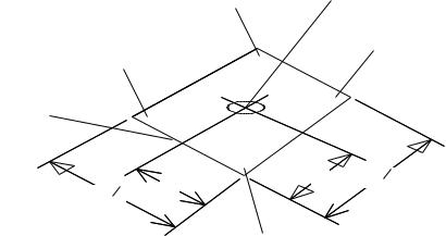
Refer to Table 7 for unit weights and to Figure 4 for approximate center of gravity.
CLEARANCES
All units require certain clearances for proper operation and service. Refer to Figure 5 for the clearances required for combustion, construction, servicing and proper unit operation.
WARNING: Do not permit overhanging structures or shrubs to obstruct the condenser air discharge, combustion air inlet or vent outlet.
DUCT WORK
These units are adaptable to downflow use as well as rear supply and return air duct openings. To convert to downflow, use the following steps:
1.Remove the duct covers found in the bottom return and supply air duct openings. There are four (4) screws securing each duct cover (save these screws to use later).
2.Install the duct covers, removed in step one, to the rear supply and return air duct openings. Secure with the four
(4) screws used in step one.
3.Seal the duct covers with silicone caulk.
Duct work should be designed and sized according to the methods of the Air Conditioning Contractors of America (ACCA), as set forth in their Manual D.
A closed return duct system shall be used. This shall not preclude use of economizers or ventilation air intake. Flexible joints may be used in the supply and return duct work to minimize the transmission of noise.
CAUTION: When fastening duct work to the side duct flanges on the unit, insert the screws through the duct flanges only. DO NOT insert the screws through the casing. Outdoor duct work must be insulated and waterproofed.
NOTE: Be sure to note supply and return openings.
Unitary Products Group |
3 |
035-18265-001-A-0202
Refer to Figure 5 for information concerning rear and bottom supply and return air duct openings.
ROOF CURB
On applications when a roof curb is used, the unit must be positioned on the curb so the front of the unit is tight against the curb.
FILTERS
Single phase units are shipped without a filter and is the responsibility of the installer to secure a filter in the return air ductwork or install a Filter/Frame Kit (1FF0110 for the D1NA018 thru D1NA042 and 1FF0112 for the D1NA048 and D2NA060).
A filter rack and filters are standard on three phase units.
NOTE: Filters on the D1NA048 and D2NA060 units require the use of a 516" nut driver for removal.
Filters must always be used and must be kept clean. When filters become dirt laden, insufficient air will be delivered by the blower, decreasing your units efficiency and increasing operating costs and wear-and-tear on the unit and controls.
Filters should be checked monthly especially since this unit is used for both heating and cooling.
CONDENSATE DRAIN
A condensate trap is recommended to be installed in the condensate drain. The plumbing must conform to local codes. Use a sealing compound on male pipe threads. Install the condensate drain line (34“ NPTF) to spill into an open drain.
SERVICE ACCESS
Access to all serviceable components is provided by the following removable panels:
•Blower compartment
•Gas control/electrical service access
Refer to Figure 5 for location of these access panels and minimum clearances.
THERMOSTAT
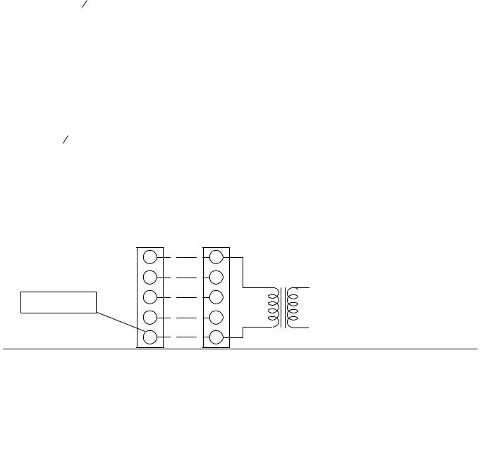
The room thermostat should be located on an inside wall approximately 56" above the floor where it will not be subject to drafts, sun exposure or heat from electrical fixtures or appliances. Follow manufacturer's instructions enclosed with the thermostat for general installation procedure. Four color coded insulated wires (minimum #18 AWG) should be used to connect thermostat to unit. See Figure 1.
POWER AND CONTROL WIRING
Field wiring to the unit must conform to provisions of the current N.E.C. ANSI/NFPA No. 70 or C.E.C. and/or local ordinances. The unit must be electrically grounded in accordance with local codes or, in their absence, with the N.E.C./C.E.C. Voltage tolerances which must be maintained at the compressor terminals during starting and running conditions are indicated on the unit Rating Plate and Table 8.
The wiring entering the cabinet must be provided with mechanical strain relief.
A fused disconnect switch should be field provided for the unit. If any of the wire supplied with the unit must be replaced, replacement wire must be of the type shown on the wiring diagram.
Electrical line must be sized properly to carry the load. Each unit must be wired with a separate branch circuit fed directly from the meter panel and properly fused.
Refer to Figure 1 for typical field wiring and to the appropriate unit wiring diagram for control circuit and power wiring information.
COMPRESSORS
Units are shipped with compressor mountings factory-adjusted for shipping. CAUTION: Loosen compressor mounting bolts half turn before operating unit.
THERMOSTAT |
CONTROL WIRING |
|
** = Minimum wire size of 18 AWG |
R |
R |
wire shuold be used for all field |
|
|
installed 24 volt wire. |
G |
G |
|
||
PROGRAMABLE |
Y |
Y |
THERMOSTAT ONLY |
|
|
|
W |
W |
|
|
NOTE: |
|
|
|
HEAT ANTICIPATOR |
|
|
|
SHOULD BE SET AT 0.35 |
|
|
|
AMPS FOR ALL MODELS. |
|
|
|
|
|
|
CAUTION: Label all wires prior |
||
|
|
to disconnection when |
|
|
24 VOLT |
servicing controls. |
|
|
|||
|
|||
|
Wiring errors can cause |
||
|
TRANSFORMER |
improper and dangerous |
|
operation. Verify proper operation after servicing.
CC
P O W E R
WIRING
REFER TO ELECTRICAL
DATA TABLES TO SIZE THE
DISCONNECT SWITCH,
WIRING & OVERCURRENT
FIG. 1 - TYPICAL FIELD WIRING DIAGRAM
REFER TO ELECTRICAL DATA TABLES TO SIZE THE DISCONNECT SWITCH, WIRING & OVERCURRENT
4 |
Unitary Products Group |
Scroll compressors operate in one direction only. If a three phase scroll compressor is experiencing:
•Low amperage draw
•Similar discharge and suction pressures
•Increased noise level
then the compressor is operating in reverse. To correct this condition, switch any two (2) line voltage leads at the contactor. Please note, single phase scroll compressor will start and run in one direction only. The reverse operation is not a concern.
COMBUSTION DISCHARGE
TABLE 2 - NATURAL GAS APPLICATION DATA
Input |
Output |
Available |
Gas |
Number |
Temp. Rise ° F |
|||
Capacity |
Capacity |
On |
Rate1 |
of |
At Full Input2 |
|||
(Mbh)3 |
(Mbh) |
Models |
Ft.3/Hr. |
Burners |
Min. |
Max. |
||
45 |
36 |
11 , 2, 2 12, 3 & |
42 |
2 |
25 |
55 |
||
2 3 12 TON |
||||||||
70 |
56 |
2 & 2 12 |
TON |
65 |
3 |
30 |
60 |
|
3 & 3 12 |
TON |
65 |
3 |
25 |
55 |
|||
|
|
|||||||
90 |
72 |
3 & 3 12 |
TON |
84 |
4 |
30 |
60 |
|
80 |
64 |
4 & 5 TON |
74 |
3 |
25 |
55 |
||
108 |
86 |
4 & 5 TON |
100 |
4 |
30 |
60 |
||
135 |
108 |
4 & 5 TON |
126 |
5 |
35 |
65 |
||
1 Based on 1075 BTU/Ft.3.
2 The air flow must be adjusted to obtain a temperature rise within the range shown. Continuous return air temperatures should not be below 55°F.
3 Heating capacity valid for elevations up to 2000 feet above sea level. For elevations above 2000 feet, rated capacity should be reduced by 4% for each 1000 feet above sea level.
TABLE 3 - PROPANE (LP) GAS APPLICATION DATA
Input |
Output |
Available |
Gas |
Number |
Temp. Rise ° F |
|||
Capacity |
Capacity |
On |
Rate1 |
of |
At Full Input2 |
|||
(Mbh)3 |
(Mbh) |
Models |
Ft.3/Hr. |
Burners |
Min. |
Max. |
||
45 |
36 |
11 , 2, 2 12, 3 & |
18 |
2 |
25 |
55 |
||
2 3 12 TON |
||||||||
70 |
56 |
2 & 2 12 |
TON |
28 |
3 |
30 |
60 |
|
3 & 3 12 |
TON |
28 |
3 |
25 |
55 |
|||
|
|
|||||||
90 |
72 |
3 & 3 12 |
TON |
36 |
4 |
30 |
60 |
|
80 |
64 |
4 & 5 TON |
32 |
3 |
25 |
55 |
||
108 |
86 |
4 & 5 TON |
43 |
4 |
30 |
60 |
||
135 |
108 |
4 & 5 TON |
54 |
5 |
35 |
65 |
||
1 Based on 2500 BTU/Ft.3.
2 The air flow must be adjusted to obtain a temperature rise within the range shown. Continuous return air temperatures should not be below 55°F.
3 Heating capacity valid for elevations up to 2000 feet above sea level. For elevations above 2000 feet, rated capacity should be reduced by 4% for each 1000 feet above sea level.
4 Propane applications are accomplished by field installation of a Propane Conversion Accessory, Model 1NP0805 for 1.5 thru 3.5 ton units and Model 1NP0806 for 4 and 5 ton units.
TABLE 4 - NATURAL GAS PIPE SIZING CHART
Length |
|
Nominal Inches Iron Pipe Size |
|
|||
in |
1/2 in. |
|
3/4 in. |
1 in. |
|
1-1/4 in. |
Feet |
|
|
||||
|
|
|
|
|
|
|
10 |
132 |
|
278 |
520 |
|
1,050 |
20 |
92 |
|
190 |
350 |
|
730 |
30 |
73 |
|
152 |
285 |
|
590 |
40 |
63 |
|
130 |
245 |
|
500 |
50 |
56 |
|
115 |
215 |
|
440 |
60 |
50 |
|
105 |
195 |
|
400 |
70 |
46 |
|
96 |
180 |
|
370 |
80 |
43 |
|
90 |
170 |
|
350 |
90 |
40 |
|
84 |
160 |
|
320 |
100 |
38 |
|
79 |
150 |
|
305 |
Maximum Capacity of Pipe in Cubic Feet of Gas Per Hour (Based Upon A Pressure Drop of 0.3 Inch Water Column and 0.6 Specific Gravity Gas).
035-18265-001-A-0202
GAS PIPING
Proper sizing of gas piping depends on the cubic feet per hour of gas flow required, specific gravity of the gas and the length of run. “National Fuel Gas Code” Z223.1 or CAN/CGA B149.1 or
.2 should be followed in all cases unless superseded by local codes or gas company requirements. Refer to Tables 4 and 5.
The heating value of the gas may differ with locality. The value should be checked with the local gas utility.
NOTE: There may be a local gas utility requirement specifying a minimum diameter for gas piping. All units require a 1/2 inch pipe connection at the gas valve.
GAS CONNECTION
The gas supply line can be routed through the hole located on the left side of the unit. Refer to Figure 5 to locate these access openings. Typical supply piping arrangements are shown in Figure 2.
AUTOMATIC
GAS VALVE
12 x 12 UNION
12 x 12 GAS COCK
12 - 14 NPT
DRIP LEG
FIG. 2 - EXTERNAL SUPPLY CONNECTION
EXTERNAL SHUT-OFF
Gas piping recommendations:
1.A drip leg and a ground joint union must be installed in the gas piping.
2.When required by local codes, a manual shut-off valve may have to be installed outside of the unit.
TABLE 5 - PROPANE (LP) GAS PIPE SIZING CHART
Length |
|
Nominal Inches Iron Pipe Size |
|
|||
in |
1/2 in. |
|
3/4 in. |
1 in. |
|
1-1/4 in. |
Feet |
|
|
||||
|
|
|
|
|
|
|
10 |
275 |
|
567 |
1,071 |
|
2,205 |
20 |
189 |
|
393 |
732 |
|
1,496 |
30 |
152 |
|
315 |
590 |
|
1,212 |
40 |
129 |
|
267 |
504 |
|
1,039 |
50 |
114 |
|
237 |
448 |
|
913 |
60 |
103 |
|
217 |
409 |
|
834 |
70 |
96 |
|
196 |
378 |
|
771 |
80 |
89 |
|
185 |
346 |
|
724 |
90 |
83 |
|
173 |
322 |
|
677 |
100 |
78 |
|
162 |
307 |
|
630 |
Maximum Capacity of Pipe in Thousands of BTU Per Hour (Based Upon A Pressure Drop of 0.5 Inch Water Column).
Unitary Products Group |
5 |
035-18265-001-A-0202
3.Use wrought iron or steel pipe for all gas lines. Pipe dope should be applied sparingly to male threads only.
CAUTION: If flexible stainless steel tubing is allowed by the authority having jurisdiction, wrought iron or steel pipe must be installed at the gas valve and extend a minimum of two (2) inches outside of the unit casing.
WARNING: Natural gas may contain some propane. Propane, being an excellent solvent, will quickly dissolve white lead or most standard commercial compounds. Therefore, a special pipe dope must be applied when wrought iron or steel pipe is used. Shellac base compounds such as Gaskolac or Stalastic, and compounds such as Rectorseal #5, Clyde's or John Crane may be used.
4.All piping should be cleaned of dirt and scale by hammering on the outside of the pipe and blowing out the loose dirt and scale. Before initial start-up, be sure that all of the gas lines external to the unit have been purged of air.
5.The gas supply should be a separate line and installed in accordance with all safety codes as prescribed under “Limitations”. After the gas connections have been completed, open the main shut-off valve admitting normal gas pressure to the mains. Check all joints for leaks with soap solution or other material suitable for the purpose. NEVER USE A FLAME.
6.The furnace and its individual manual shut-off valve must be disconnected from the gas supply piping system during any pressure testing of that system at test pressures in excess of 1/2 psig (3.48 kPa).
The furnace must be isoulated from the gas supply piping system by closing its individual manual shut-off valve during any pressure testing of the gas supply piping system at test pressures equal to or less than 1/2 psig (3.48 kPa).
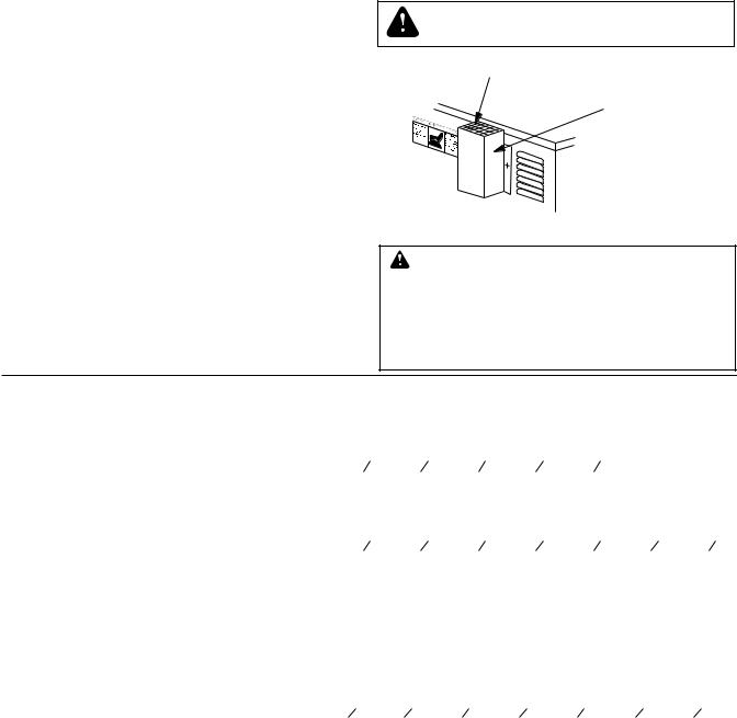
FLUE VENT HOOD
The flue vent hood with screen is not shipped attached. This hood must be installed to assure proper unit operation. The hood must be fastened to the outside of the side gas control/electrical compartment with the screws provided in the bag attached to the inside of the gas control/electrical compartment, see Figure 3.
The unit is controlled by a conventional four wire heating/cooling thermostat common to this class of equipment.
WARNING: FLUE HOOD SURFACES
MAY BE HOT.
V E N T O U T L E T S C R E E N
F L U E V E N T O U T
A I R H O O D
FIG. 3 - FLUE VENT OUTLET AIR HOOD
CAUTION
The flue exhaust hood must be properly installed and within the recommended clearances. Further communications and action must be given to the home or building owner(s) to eleiminate any unauthorized humon contact around this area during the heating cycle. Flue hood surface and immediate area is designed to operate at high temperatures during the heating cycle.
TABLE 6 - PHYSICAL DATA
|
MODELS |
|
|
|
DNA |
|
|
|
|
|
018 |
024 |
030 |
036 |
042 |
048 |
060 |
||
|
|
||||||||
EVAPORATOR |
CENTRIFUGAL BLOWER (Dia. x Wd. in.) |
10 X 8 |
10 X 8 |
10 X 8 |
11 x 10 |
11 x 10 |
12 x 11 |
12 x 11 |
|
BLOWER |
FAN MOTOR HP (Three Speed) |
12 |
12 |
12 |
34 |
34 |
1.0 |
1.0 |
|
EVAPORATOR |
ROWS DEEP |
2 |
2 |
2 |
2 |
3 |
3 |
3 |
|
FINS PER INCH |
14 |
13 |
13 |
15 |
13 |
13 |
13 |
||
COIL |
|||||||||
FACE AREA (Sq. Ft.) |
2.25 |
3.5 |
3.5 |
3.5 |
3.5 |
4.5 |
4.5 |
||
|
|||||||||
CONDENSER |
PROPELLER DIA. (in.) |
22 |
22 |
22 |
22 |
22 |
22 |
22 |
|
FAN MOTOR HP |
14 |
14 |
14 |
14 |
14 |
14 |
14 |
||
FAN |
|||||||||
NOM. CFM TOTAL |
1,800 |
2,200 |
2,400 |
2,400 |
2,400 |
3,000 |
3,000 |
||
|
|||||||||
CONDENSER |
ROWS DEEP |
1 |
1 |
1 |
1 |
1 |
1 |
1 |
|
FINS PER INCH |
13 |
13 |
16 |
20 |
20 |
20 |
20 |
||
COIL |
|||||||||
FACE AREA (Sq. Ft.) |
8.3 |
8.3 |
11.7 |
11.7 |
11.7 |
14.8 |
14.8 |
||
|
|||||||||
CHARGE |
REFRIGERANT 22 (lbs./oz.) |
3 / 2 |
3 / 6 |
4 / 12 |
4 / 3 |
4 / 12 |
6 / 0 |
5 / 4 |
|
FILTER* |
FACE AREA (Sq. Ft.) / SIZE (NOMINAL) |
2.6/20x20 |
2.6/20x20 |
2.6/20x20 |
2.6/20x20 |
2.6/20x20 |
3.3/20x12 |
3.3/20x12 |
|
|
NATURAL GAS BURNER ORIFICE NO. |
43 |
43 |
43 |
43 |
43 |
40 |
40 |
|
|
(Qty./Drill size) |
||||||||
FURNACE |
|
|
|
|
|
|
|
||
PROPANE BURNER ORIFICE NO. |
55 |
55 |
55 |
55 |
55 |
53 |
53 |
||
SECTION |
|||||||||
(Qty./Drill size) |
|||||||||
|
|
|
|
|
|
|
|
||
|
GAS CONNECTION SIZE |
12 NPTI |
12 NPTI |
12 NPTI |
12 NPTI |
12 NPTI |
12 NPTI |
12 NPTI |
|
COMPRESSOR |
HERMETICALLY SEALED |
R |
R |
R |
R |
R |
S |
S |
|
TYPE |
(R = RECIPROCATING, S = Scroll) |
||||||||
|
|
|
|
|
|
|
*= Three phase 018 thru 042 size units are supplied with one (1) filter and on three phase 048 and 060 size units two (2) filters are supplied. Single phase units are shipped without filters. See “FILTERS” on page 4.
6 |
Unitary Products Group |
035-18265-001-A-0202
TABLE 7 - UNIT WEIGHTS
|
UNIT |
UNIT |
CORNER OPERATING WEIGHTS |
|
||||
MODEL |
SHIPPING |
OPERATING |
(lbs., location, see Figure 4) |
|||||
DNA |
WEIGHT |
WEIGHT |
|
|
|
|
|
|
“A” |
“B” |
“C” |
|
“D” |
||||
|
(lbs.) |
(lbs.) |
|
|||||
|
|
|
|
|
|
|
|
|
|
|
|
|
|
|
|
|
|
018 |
365 |
360 |
91 |
88 |
89 |
|
92 |
|
|
|
|
|
|
|
|
|
|
024 |
365 |
360 |
91 |
88 |
89 |
|
92 |
|
|
|
|
|
|
|
|
|
|
030 |
395 |
390 |
98 |
95 |
96 |
|
99 |
|
|
|
|
|
|
|
|
|
|
036 |
400 |
395 |
100 |
96 |
98 |
|
101 |
|
|
|
|
|
|
|
|
|
|
042 |
405 |
410 |
104 |
100 |
101 |
|
105 |
|
|
|
|
|
|
|
|
|
|
048 |
475 |
470 |
119 |
115 |
116 |
|
120 |
|
|
|
|
|
|
|
|
|
|
060 |
480 |
475 |
120 |
116 |
117 |
|
122 |
|
|
|
|
|
|
|
|
|
|
CORNER “D” |
CENTER OF GRAVITY |
|
|
|
CORNER “C” |
CORNER “A” |
|
FRONT
OF
UNIT
24 |
47 14 |
49 18 |
25 |
FIG. 4 - CENTER OF GRAVITY
CORNER “B”
TABLE 8 - ELECTRICAL DATA
|
|
VOLTAGE |
|
|
COND. |
SUPPLY |
|
MAX. |
MAX. |
|
|
|||
|
POWER SUP- |
LIMITATIONS |
COMPRESSOR |
AIR |
MINIMUM |
FUSE |
HACR |
UNIT |
TRANSFORMER |
|||||
MODEL |
FAN |
|||||||||||||
|
1 |
|
|
BLOWER |
CIRCUIT |
SIZE, |
BREAKER |
POWER |
SIZE (VA) |
|||||
DNA |
PLY |
|
|
|
|
|
MOTOR, |
|||||||
|
|
|
|
|
MOTOR, |
AMPACITY |
AMPS |
SIZE, |
FACTOR |
3 |
||||
MIN. |
|
MAX. |
RLA |
LRA |
||||||||||
|
|
|
FLA |
FLA |
|
2 |
AMPS |
|
|
|||||
|
|
|
|
|
|
|
|
|
|
|
|
|||
018 |
208/230-1-60 |
187 |
|
253 |
9.0 |
48.0 |
1.1 |
2.2 |
14.5 |
20 |
20 |
.96 |
40 |
|
024 |
208/230-1-60 |
187 |
|
253 |
11.5 |
60.0 |
1.1 |
2.2 |
17.7 |
25 |
25 |
.96 |
40 |
|
030 |
208/230-1-60 |
187 |
|
253 |
14.7 |
73.0 |
1.1 |
2.2 |
21.7 |
30 |
30 |
.96 |
40 |
|
036 |
208/230-1-60 |
187 |
|
253 |
17.3 |
94.0 |
1.1 |
3.5 |
26.2 |
35 |
35 |
.96 |
40 |
|
042 |
208/230-1-60 |
187 |
|
253 |
20.5 |
120.0 |
1.1 |
3.5 |
30.2 |
40 |
40 |
.96 |
40 |
|
048 |
208/230-1-60 |
187 |
|
253 |
24.4 |
140.0 |
1.3 |
7.0 |
38.8 |
50 |
50 |
.96 |
40 |
|
060 |
208/230-1-60 |
187 |
|
253 |
28.9 |
175.0 |
1.3 |
7.0 |
44.4 |
60 |
60 |
.96 |
40 |
|
|
|
|
|
|
|
|
|
|
|
|
|
|
|
|
036 |
208/230-3-60 |
187 |
|
253 |
10.9 |
78.0 |
1.1 |
3.5 |
18.2 |
25 |
25 |
.96 |
75 |
|
042 |
208/230-3-60 |
187 |
|
253 |
14.1 |
110.0 |
1.1 |
3.5 |
22.2 |
30 |
30 |
.96 |
75 |
|
048 |
208/230-3-60 |
187 |
|
253 |
14.1 |
105 |
1.3 |
7.0 |
25.9 |
35 |
35 |
.96 |
75 |
|
060 |
208/230-3-60 |
187 |
|
253 |
15.5 |
125 |
1.3 |
7.0 |
29.5 |
40 |
40 |
.96 |
75 |
|
|
|
|
|
|
|
|
|
|
|
|
|
|
|
|
036 |
460-3-60 |
414 |
|
504 |
5.8 |
40.0 |
0.6 |
1.8 |
9.6 |
15 |
15 |
.96 |
75 |
|
042 |
460-3-60 |
414 |
|
504 |
7.1 |
54.0 |
0.6 |
1.8 |
11.2 |
15 |
15 |
.96 |
75 |
|
048 |
460-3-60 |
414 |
|
504 |
7.1 |
55.0 |
0.7 |
3.5 |
13.1 |
20 |
20 |
.96 |
75 |
|
060 |
460-3-60 |
414 |
|
504 |
8.8 |
66.5 |
0.7 |
3.5 |
15.4 |
20 |
20 |
.96 |
75 |
|
|
|
|
|
|
|
|
|
|
|
|
|
|
|
|
036 |
575-3-60 |
518 |
|
630 |
4.5 |
32.0 |
0.4 |
1.5 |
7.5 |
15 |
15 |
.96 |
75 |
|
042 |
575-3-60 |
518 |
|
630 |
5.8 |
44.0 |
0.4 |
1.5 |
9.1 |
15 |
15 |
.96 |
75 |
|
048 |
575-3-60 |
518 |
|
630 |
5.7 |
45.0 |
0.6 |
2.8 |
10.5 |
15 |
15 |
.96 |
75 |
|
060 |
575-3-60 |
518 |
|
630 |
7.1 |
50.0 |
0.6 |
2.8 |
12.3 |
15 |
15 |
.96 |
75 |
|
Note; Electrical data based on 104°F outdoor air ambient temperature. |
|
|
1 |
= Rated in accordance with ARI Standard 110, utilization range “A”. |
2 = Dual element, time delay type. |
3 |
= If economizer or motorized damper are to be used, 75 VA is required. Refer to price pages for future details. |
|
Unitary Products Group |
7 |
 Loading...