


 Loading...
GZKDJRRJDGHZ2[JZFJR
R-410A AFFINITY SERIES
DNX024-048 2-4 Ton
TABLE OF CONTENTS
General . . . . . . . . . . . . . . . . . . . . . . . . . . . . . . . . . . . . . . . . . |
. 1 |
Phasing . . . . . . . . . . . . . . . . . . . . . . . . . . . . . . . . . . . . . . . |
15 |
Installation . . . . . . . . . . . . . . . . . . . . . . . . . . . . . . . . . . . . . . . . |
3 |
Gas Heat. . . . . . . . . . . . . . . . . . . . . . . . . . . . . . . . . . . . . . |
15 |
Limitations . . . . . . . . . . . . . . . . . . . . . . . . . . . . . . . . . . . . |
3 |
Flue Vent Hood . . . . . . . . . . . . . . . . . . . . . . . . . . . . . . . . . |
16 |
Location. . . . . . . . . . . . . . . . . . . . . . . . . . . . . . . . . . . . . . . . |
5 |
Airflow Performance . . . . . . . . . . . . . . . . . . . . . . . . . . . . . . . |
18 |
Rigging And Handling . . . . . . . . . . . . . . . . . . . . . . . . . . . . . |
5 |
Blower Speed Selection . . . . . . . . . . . . . . . . . . . . . . . . . . |
21 |
Ductwork . . . . . . . . . . . . . . . . . . . . . . . . . . . . . . . . . . . . . . . |
9 |
Operation . . . . . . . . . . . . . . . . . . . . . . . . . . . . . . . . . . . . . . . |
22 |
Roof Curb . . . . . . . . . . . . . . . . . . . . . . . . . . . . . . . . . . . . . . |
9 |
Heating Sequence Of Operation. . . . . . . . . . . . . . . . . . . . |
22 |
Filters . . . . . . . . . . . . . . . . . . . . . . . . . . . . . . . . . . . . . . . . . |
9 |
Cooling Sequence Of Operations . . . . . . . . . . . . . . . . . . . |
24 |
Condensate Drain . . . . . . . . . . . . . . . . . . . . . . . . . . . . . . . . |
9 |
Start-Up . . . . . . . . . . . . . . . . . . . . . . . . . . . . . . . . . . . . . . . . . |
25 |
Service Access . . . . . . . . . . . . . . . . . . . . . . . . . . . . . . . . . |
10 |
Adjustment of Temperature Rise . . . . . . . . . . . . . . . . . . . |
27 |
Thermostat . . . . . . . . . . . . . . . . . . . . . . . . . . . . . . . . . . . . |
10 |
Checking Gas Heat Input . . . . . . . . . . . . . . . . . . . . . . . . . . . |
27 |
Power And Control Wiring. . . . . . . . . . . . . . . . . . . . . . . . . |
10 |
Natural Gas. . . . . . . . . . . . . . . . . . . . . . . . . . . . . . . . . . . . |
27 |
Compressors. . . . . . . . . . . . . . . . . . . . . . . . . . . . . . . . . . . |
15 |
Typical Wiring Diagrams . . . . . . . . . . . . . . . . . . . . . . . . . . . . |
28 |
LIST OF TABLES
1 |
Unit Limitations . . . . . . . . . . . . . . . . . . . . . . . . . . . . . . . . . |
4 |
11 |
Propane (LP) Gas Application Data-Single Stage . . . . . |
17 |
2 |
Weights and Dimensions . . . . . . . . . . . . . . . . . . . . . . . . . |
6 |
12 |
Propane (LP) Gas Application Data-Two Stage . . . . . . . |
17 |
3 |
Unit Accessory Weights . . . . . . . . . . . . . . . . . . . . . . . . . . |
6 |
13 |
Side Duct Application . . . . . . . . . . . . . . . . . . . . . . . . . . . |
18 |
4 |
Unit Dimensions . . . . . . . . . . . . . . . . . . . . . . . . . . . . . . . . |
7 |
14 |
Bottom Duct Application . . . . . . . . . . . . . . . . . . . . . . . . . |
19 |
5 |
Unit Clearances . . . . . . . . . . . . . . . . . . . . . . . . . . . . . . . . |
7 |
15 |
Additional Static Resistance . . . . . . . . . . . . . . . . . . . . . . |
21 |
6 |
Electrical Data . . . . . . . . . . . . . . . . . . . . . . . . . . . . . . . . . |
12 |
16 |
Indoor Blower Specifications. . . . . . . . . . . . . . . . . . . . . . |
21 |
7 |
Natural Gas Pipe Sizing Chart . . . . . . . . . . . . . . . . . . . . |
16 |
17 |
Delay Profile . . . . . . . . . . . . . . . . . . . . . . . . . . . . . . . . . . |
22 |
8 |
Propane (LP) Gas Pipe Sizing Chart . . . . . . . . . . . . . . . |
16 |
18 |
Ignition Control Board FLASH CODES. . . . . . . . . . . . . . |
24 |
9 |
Natural Gas Application Data-Single Stage . . . . . . . . . . |
17 |
19 |
Gas Rate Cubic Feet Per Hour . . . . . . . . . . . . . . . . . . . . |
27 |
10 |
Natural Gas Application Data-Two Stage . . . . . . . . . . . . |
17 |
|
|
|
LIST OF FIGURES
1 |
Component Location . . . . . . . . . . . . . . . . . . . . . . . . . . . |
. 4 |
10 |
Typical Field Control Wiring Diagram Two Stage |
12 |
2 |
Unit 4 Point Load Weight . . . . . . . . . . . . . . . . . . . . . . . . |
. 6 |
11 |
Thermostat - Two Stage Gas Heat . . . . . . . . . . . . . . . . |
|
3 |
Unit Dimensions . . . . . . . . . . . . . . . . . . . . . . . . . . . . . . . |
. 7 |
Typical Field Power Wiring Diagram . . . . . . . . . . . . . . . |
12 |
|
4 |
Dimensions Front and Bottom . . . . . . . . . . . . . . . . . . . . . |
8 |
12 |
External Supply Connection External Shut-Off . . . . . . . |
15 |
5 |
Dimensions Back and Bottom . . . . . . . . . . . . . . . . . . . . . |
8 |
13 |
Flue Vent Outlet Air Hood . . . . . . . . . . . . . . . . . . . . . . . |
16 |
6 |
Roof Curb. . . . . . . . . . . . . . . . . . . . . . . . . . . . . . . . . . . . . |
9 |
14 |
Control Board Speed Tap Location . . . . . . . . . . . . . . . . |
22 |
7 |
Typical Field Control Wiring Diagram Single Stage |
10 |
15 |
Single Stage Gas Valve Front . . . . . . . . . . . . . . . . . . . . |
25 |
8 |
Thermostat - Single Stage Gas Heat . . . . . . . . . . . . . . . |
16 |
Two Stage Gas Valve Front . . . . . . . . . . . . . . . . . . . . . . |
26 |
|
Typical Field Control Wiring Diagram Single Stage |
11 |
17 |
Single Stage Gas Valve Rear . . . . . . . . . . . . . . . . . . . . |
26 |
|
9 |
Thermostat - Two Stage Gas Heat . . . . . . . . . . . . . . . . |
18 |
Two Stage Gas Valve Rear . . . . . . . . . . . . . . . . . . . . . . |
26 |
|
Typical Field Control Wiring Diagram Two Stage |
11 |
19 |
Proper Flame Adjustment . . . . . . . . . . . . . . . . . . . . . . . |
26 |
|
|
Thermostat - Single Stage Gas Heat . . . . . . . . . . . . . . . |
20 |
R-410A Quick Reference Guide . . . . . . . . . . . . . . . . . . |
36 |
General |
Safety Considerations |
|||
YORK |
® |
Affinity Model DNX units are cooling/heating air |
This is a safety alert symbol . When you see this symbol on |
|
|
labels or in manuals, be alert to the potential for personal injury. |
|||
conditioners designed for outdoor installation. Only gas piping, |
||||
|
||||
electric power and duct connections are required at the point of installation.
The single or two stage gas-fired heaters have spark to pilot ignition. The tubular heat exchangers are aluminized steel.
The refrigerant system is fully charged with R-410A Refrigerant, and is tested and factory sealed.
Understand and pay particular attention the signal words
DANGER, WARNING or CAUTION.
DANGER indicates an imminently hazardous situation, which, if not avoided, will result in death or serious injury.
WARNING indicates a potentially hazardous situation, which, if not avoided, could result in death or serious injury.
CAUTION indicates a potentially hazardous situation, which, if not avoided may result in minor or moderate injury. It is also used to alert against unsafe practices and hazards involving only property damage.
279550-YIM-A-0207
279550-YIM-A-0207
Improper installation may create a condition where the operation of the product could cause personal injury or property damage. Improper installation, adjustment, alteration, service or maintenance can cause injury or property damage. Refer to this manual for assistance or for additional information, consult a qualified contractor, installer or service agency.
This product must be installed in strict compliance with the installation instructions and any applicable local, state and national codes including, but not limited to building, electrical, and mechanical codes.
Before performing service or maintenance operations on unit, turn off main power switch to unit. Electrical shock could cause personal injury. Improper installation, adjustment, alteration, service or maintenance can cause injury or property damage. Refer to this manual. For assistance or additional information consult a qualified installer, service agency or the gas supplier.
This system uses R-410A Refrigerant which operates at higher pressures than R-22. No other refrigerant may be used in this system. Gage sets, hoses, refrigerant containers and recovery systems must be designed to handle R-410A. If you are unsure, consult the equipment manufacturer. Failure to use R-410A compatible servicing equipment may result in property damage or injury.
If the information in this manual is not followed exactly, a fire or explosion may result causing property damage, personal injury or loss of life.
Do not store or use gasoline or other flammable vapors and liquids in the vicinity of this or any other appliance. WHAT TO DO IF YOU SMELL GAS:
a.Do not try to light any appliance.
b.Do not touch any electrical switch; do not use any phone in your building.
c.Immediately call your gas supplier from a neighbor’s phone. Follow the gas supplier’s instructions.
d.If you cannot reach your gas supplier, call the fire department.
Installation and service must be performed by a qualified installer, service agency or the gas supplier.
Due to system pressure, moving parts, and electrical components, installation and servicing of air conditioning equipment can be hazardous. Only qualified, trained service personnel should install, repair, or service this equipment. Untrained personnel can perform basic maintenance functions of cleaning coils and filters and replacing filters.
Observe all precautions in the literature, labels, and tags accompanying the equipment whenever working on air conditioning equipment. Be sure to follow all other applicable safety precautions and codes including ANSI Z223.1 or CSAB149.1- latest edition.
Wear safety glasses and work gloves. Use quenching cloth and have a fire extinguisher available during brazing operations.
Inspection
As soon as a unit is received, it should be inspected for possible damage during transit. If damage is evident, the extent of the damage should be noted on the carrier’s freight bill. A separate request for inspection by the carrier’s agent should be made in writing.
This product must be installed in strict compliance with the enclosed installation instructions and any applicable local, state and national codes including, but not limited to, building, electrical, and mechanical codes.
The furnace and its individual shut-off valve must be disconnected from the gas supply piping system during any pressure testing at pressures in excess of 1/2 PSIG.
Pressures greater than 1/2 PSIG will cause gas valve damage resulting in a hazardous condition. If it is subjected to a pressure greater than 1/2 PSIG, the gas valve must be replaced.
The furnace must be isolated from the gas supply piping system by closing its individual manual shut-off valve during any pressure testing of the gas supply piping system at test pressures equal to or less than 1/2 PSIG
Reference
Additional information is available in the following reference forms:
•Technical Guide - DNX024-048, 291625
•General Installation - DNX024-048, 279550
Renewal Parts
Contact your local York® parts distribution center for authorized replacement parts.
Approvals
Design certified by CSA as follows:
1.For use as a cooling only unit, cooling unit with supplemental electric heat or a forced air furnace.
2.For outdoor installation only.
2 |
Unitary Products Group |
279550-YIM-A-0207
3.For installation on combustible material and may be installed directly on combustible flooring or, in the U.S., on wood flooring or Class A, Class B or Class C roof covering materials.
4.For use with natural gas (convertible to LP with kit).
This product must be installed in strict compliance with the enclosed installation instructions and any applicable local, state, and national codes including, but not limited to, building, electrical, and mechanical codes.
Improper installation may create a condition where the operation of the product could cause personal injury or property damage.
This system uses R-410A Refrigerant which operates at higher pressures than R-22. No other refrigerant may be used in this system.
Nomenclature
|
|
|
|
D |
1 |
|
NX |
036 |
|
N |
|
036 |
06 |
|
|
|
|
|||||||||
|
|
|
|
|
|
|
|
|
|
|
|
|
|
|
|
|
|
|
|
|
|
|
|
|
|
|
|
|
|
|
|
|
|
|
|
|
|
|
|
|
|
|
|
|
|
|
|
|
|
|
|
|
|
Product Category |
|
|
|
|
|
|
|
|
|
|
|
|
|
|
|
|
|
|
|
|
|
|
Voltage Code |
|
||
D = Single Package Air Conditioner |
|
|
|
|
|
|
|
|
|
|
|
|
|
|
|
|
|
|
|
|
|
|
06 = 208/230-1-60 |
|
||
|
|
|
|
|
|
|
|
|
|
|
|
|
|
|
|
|
|
|
|
|
|
|
|
25 = 208/230-3-60 |
|
|
|
|
|
|
|
|
|
|
|
|
|
|
|
|
|
|
|
|
|
|
|
|
|
||||
|
Product Generation |
|
|
|
|
|
|
|
|
|
|
|
|
|
|
|
|
46 = 460-3-60 |
|
|||||||
|
1 = 1st Generation |
|
|
|
|
|
|
|
|
|
|
|
|
|
|
|
|
|
|
|
||||||
|
|
|
|
|
|
|
|
|
|
|
|
|
|
|
|
|
|
Nominal Gas Heating Output Capacity |
||||||||
|
2 = 2nd Generation |
|
|
|
|
|
|
|
|
|
|
|
|
|
|
|
|
|
||||||||
|
|
|
|
|
|
|
|
|
|
|
|
|
|
|
|
|
|
(Nominal Low Gas Heat Output Capacity) |
||||||||
|
|
|
|
|
|
|
|
|
|
|
|
|
|
|
Factory Installed Gas Heat |
|
|
|||||||||
|
|
Product Identifier |
|
|
|
|
|
|
|
|
|
|
|
|
|
|
|
|
036 = 36,000 BTUH |
|||||||
|
|
|
|
|
|
N = Single Stage |
|
|
|
|
||||||||||||||||
|
|
NX = R-410A 15 SEER |
|
|
|
|
|
|
|
|
|
056 = 56,000 BTUH (36,400 BTUH) |
||||||||||||||
|
|
|
|
|
|
|
D = Two Stage |
|
|
|
|
|||||||||||||||
|
|
|
|
|
|
|
|
|
|
|
065 = 65,000 BTUH |
|||||||||||||||
|
|
Gas Heat/Electric |
|
|
|
|
|
|
|
|
|
|
|
|
|
|
|
|
||||||||
|
|
|
|
|
|
|
|
|
|
|
|
|
|
|
|
|
|
072 = 72,000 BTUH (46,800 BTUH) |
||||||||
|
|
|
|
|
|
|
|
|
|
|
|
Nominal Cooling Capacity (MBH) |
|
|
090 = 90,000 BTUH (56,160 BTUH) |
|||||||||||
|
|
|
|
|
|
|
|
|
|
|
|
024 = 24,000 BTUH |
048 = 48,000 BTUH |
|
|
110 = 110,000 BTUH (70,200 BTUH) |
||||||||||
|
|
|
|
|
|
|
|
|
|
|
|
|
|
|
|
|||||||||||
|
|
|
|
|
|
|
|
|
|
|
|
036 = 36,000 BTUH |
|
|
|
|
|
|
|
|
||||||
|
|
|
|
|
|
|
|
|
|
|
|
|
|
|
|
|
|
|
|
|
|
|
|
|
|
|
Installation
Installation Safety Information
Read these instructions before continuing this appliance installation. This is an outdoor combination heating and cooling unit. The installer must assure that these instructions are made available to the consumer and with instructions to retain them for future reference.
1.Refer to the unit rating plate for the approved type of gas for this product.
2.Install this unit only in a location and position as specified on Page 5 of these instructions.
3.Never test for gas leaks with an open flame. Use commercially available soap solution made specifically for the detection of leaks when checking all connections, as specified on Pages 3 and 16 of these instructions.
4.Always install furnace to operate within the furnace's intended temperature-rise range with the duct system and within the allowable external static pressure range, as specified on the unit name/rating plate, specified on Page 17 of these instructions.
5.This equipment is not to be used for temporary heating of buildings or structures under construction.
FIRE OR EXPLOSION HAZARD
Failure to follow the safety warning exactly could result in serious injury, death or property damage.
Never test for gas leaks with an open flame. use a commercially available soap solution made specifically for the detection of leaks to check all connections. A fire or explosion may result causing property damage, personal injury or loss of life.
Limitations
These units must be installed in accordance with the following:
In U.S.A.:
1.National Electrical Code, ANSI/NFPA No. 70 - Latest Edition
2.National Fuel Gas Code, ANSI Z223.1 - Latest Edition
3.Gas-Fired Central Furnace Standard, ANSI Z21.47a. - Latest Edition
4.Local building codes, and
5.Local gas utility requirements
Unitary Products Group |
3 |
279550-YIM-A-0207
In Canada:
1.Canadian Electrical Code, CSA C22.1
2.Installation Codes, CSA - B149.1.
3.Local plumbing and waste water codes, and
4.Other applicable local codes.
Refer to unit application data found in this document.
After installation, gas fired units must be adjusted to obtain a temperature rise within the range specified on the unit rating plate.
If components are to be added to a unit to meet local codes, they are to be installed at the dealer’s and/or customer’s expense.
Size of unit for proposed installation should be based on heat loss/heat gain calculation made according to the methods of Air Conditioning Contractors of America (ACCA).
This furnace is not to be used for temporary heating of buildings or structures under construction.
|
|
|
|
Direct Drive |
|
|
Blow-Through Design With |
|
Condenser Fan Motor |
||
|
|
|
|
||
|
Reliable Aluminized Steel |
|
|
|
|
|
Tubular Heat Exchangers |
|
|
|
|
|
|
|
Highly Efficient Enhanced Copper |
||
|
|
|
Tube/Aluminum Fin Evaporator Coil |
||
|
|
|
|
Highly Efficient Enhanced Copper |
|
|
Long Lasting Powder |
|
|
Tube/Aluminum Fin Condenser Coil |
|
|
|
|
|
||
|
Paint Finish |
|
|
|
|
|
|
|
|
Decorative Protective |
|
|
|
|
|
Coil Guard |
|
|
Rear and Bottom Return Air |
|
|
High Efficiency |
|
|
|
|
Compressor Rigidly |
||
|
and Supply Airduct Openings |
|
|
||
|
|
|
Mounted |
||
|
|
|
|
||
|
|
|
|
Pilot Assembly |
|
|
Heavy Gauge |
|
|
High Grade Aluminized In-Shot Burners |
|
|
|
|
|
||
|
Removable Base Rails |
|
|
Low Voltage Terminal Block |
|
|
|
|
|
||
|
|
|
Self-Diagnostic Controls |
||
|
Direct Drive Blower Motor With |
|
|
|
|
|
Slide-Out Blower Assembly |
|
|
|
|
|
Power Draft Motor |
Automatic Gas Valve (1/2" - 14 NPTI) |
|||
|
|
|
High Voltage |
|
|
|
|
|
Terminal Block |
|
|
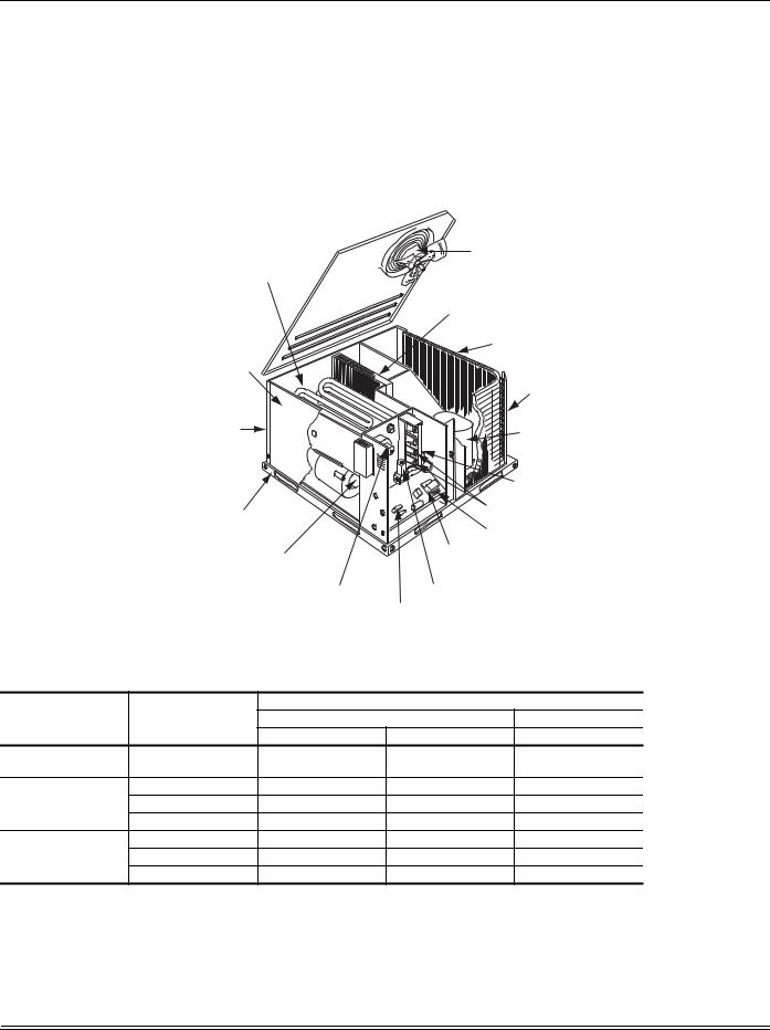
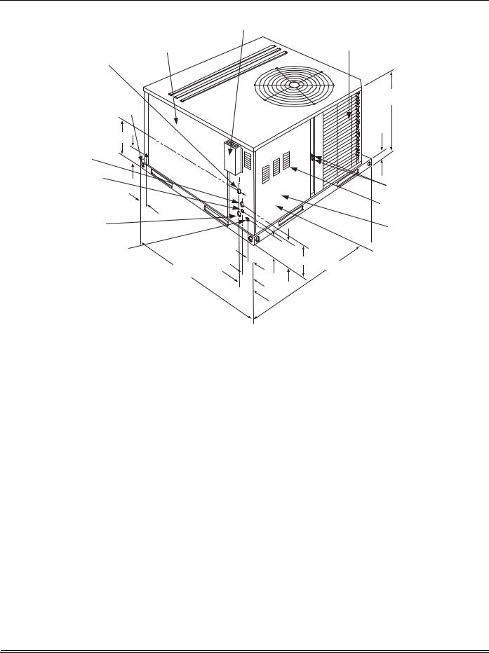
Figure 1: Component Location |
|
|
|
||
Table 1: Unit Limitations |
|
|
|
||
Size |
|
|
Unit Limitations |
||
Unit Voltage |
Applied Voltage |
Outdoor DB Temp |
|||
(Tons) |
|||||
|
Min |
Max |
Max (°F) |
||
|
|
||||
024 |
208/230-1-60 |
187 |
252 |
115 |
|
(2.0) |
|||||
|
|
|
|
||
036 |
208/230-1-60 |
187 |
252 |
115 |
|
208/230-3-60 |
187 |
252 |
115 |
||
(3.0) |
|||||
460-3-60 |
432 |
504 |
115 |
||
|
|||||
048 |
208/230-1-60 |
187 |
252 |
115 |
|
208/230-3-60 |
187 |
252 |
115 |
||
(4.0) |
|||||
460-3-60 |
432 |
504 |
115 |
||
|
|||||
4 |
Unitary Products Group |
279550-YIM-A-0207
Location
Use the following guidelines to select a suitable location for these units:
1.Unit is designed for outdoor installation only.
2.Condenser coils must have an unlimited supply of air. Where a choice of location is possible, position the unit on either north or east side of building.
3.Suitable for mounting on roof curb.
4.For ground level installation, a level pad or slab should be used. The thickness and size of the pad or slab used should meet local codes and unit weight. Do not tie the slab to the building foundation.
5.Roof structures must be able to support the weight of the unit and its options/accessories. Unit must be installed on a solid, level roof curb or appropriate angle iron frame.
6.Maintain level tolerance to 1/8” across the entire width and length of unit.
Excessive exposure of this furnace to contaminated combustion air may result in equipment damage or personal injury. Typical contaminates include: permanent wave solution, chlorinated waxes and cleaners, chlorine based swimming pool chemicals, water softening chemicals, carbon tetrachloride, Halogen type refrigerants, cleaning solvents (e.g. perchloroethylene), printing inks, paint removers, varnishes, hydrochloric acid, cements and glues, antistatic fabric softeners for clothes dryers, masonry acid washing materials.
Clearances
All units require particular clearances for proper operation and service. Installer must make provisions for adequate combustion and ventilation air in accordance with section 5.3 of Air for Combustion and Ventilation of the National Fuel Gas Code, ANSI Z223.1 – Latest Edition (in U.S.A.), or Sections 7.2, 7.3, or 7.4 of Gas Installation Codes, CSA-B149.1 (in Canada) - Latest Edition, and/or applicable provisions of the local building
codes. Refer to Table 5 for clearances required for combustible construction, servicing, and proper unit operation.
Do not permit overhanging structures or shrubs to obstruct condenser air discharge outlet, combustion air inlet or vent outlets.
Rigging And Handling
Exercise care when moving the unit. Do not remove any packaging until the unit is near the place of installation. Rig the unit by attaching chain or cable slings to the lifting holes provided in the base rails. Spreader bars, whose length exceeds the largest dimension across the unit, MUST be used across the top of the unit.
If a unit is to be installed on a roof curb other than a York® roof curb, gasketing must be applied to all surfaces that come in contact with the unit underside.
Before lifting, make sure the unit weight is distributed equally on the rigging cables so it will lift evenly.
Units may be moved or lifted with a forklift. Slotted openings in the base rails are provided for this purpose.
All panels must be secured in place when the unit is lifted.
The condenser coils should be protected from rigging cable damage with plywood or other suitable material.
Unitary Products Group |
5 |
279550-YIM-A-0207
'
&(17(5 2) )5217 *5$9,7<
2)
81,7
$ |
& |
|
; |
% |
< |
|
|
|
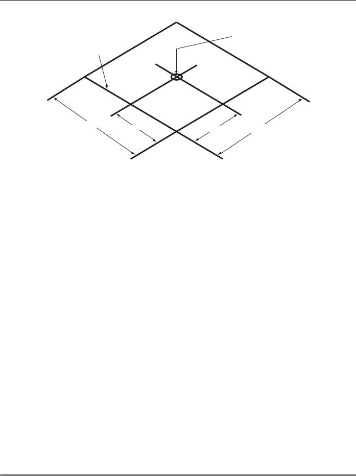
Figure 2: Unit 4 Point Load Weight
Table 2: Weights and Dimensions
Size |
Weight (lbs.) |
Center of Gravity |
4 Point Load Location (lbs.) |
||||||
(Tons) |
Shipping |
Operating |
X |
Y |
A |
B |
C |
D |
|
024 |
445 |
440 |
20 |
24.5 |
127 |
93 |
93 |
127 |
|
(2.0) |
|||||||||
|
|
|
|
|
|
|
|
||
036 |
445 |
440 |
20 |
24.25 |
126 |
91 |
93 |
129 |
|
(3.0) |
|||||||||
|
|
|
|
|
|
|
|
||
048 |
505 |
500 |
20 |
24 |
142 |
102 |
107 |
149 |
|
(4.0) |
|||||||||
|
|
|
|
|
|
|
|
||
Table 3: Unit Accessory Weights
Unit Accessory |
Model |
Weight (lbs.) |
||
Shipping |
Operating |
|||
|
|
|||
Add Economizer |
All |
45 |
40 |
|
6 |
Unitary Products Group |
279550-YIM-A-0207
|
|
9(17 $,5 287/(7 +22' |
|
|
|
||
*$6 6833/< |
%/2:(5 6(59,&( $&&(66 |
|
|
|
&21'(16(5 &2,/ |
||
&203$570(17 3$1(/ |
|
|
|
||||
',$0(7(5 +2/( |
|
|
|
|
|
|
|
137, &211(&7,21 |
|
|
|
|
|
|
|
81,7 &21'(16$7( |
|
|
|
|
|
|
|
&211(&7,21 137, |
|
|
|
|
|
$ |
|
75$3 5(&200(1'(' |
|
|
|
|
|
|
|
|
% |
|
|
|
|
|
|
+,*+ 92/7$*( |
|
|
|
|
|
|
|
|
|
|
|
|
|
|
|
&211 ',$ |
|
|
|
|
|
|
|
.12&.287 |
|
|
|
|
|
|
|
|
|
|
|
|
|
|
5()5,*(5$17 |
|
|
|
|
|
|
&211(&7,216 |
|
*$6 6833/< |
|
|
|
|
|
|
&20%867,21 $,5 |
|
|
|
|
|
,1/(7 /289(56 |
||
|
|
|
|
|
|
||
',$ .12&.287 |
|
|
|
|
|
|
)5217 |
137, &211(&7,21 |
|
|
|
|
|
|
|
/2: 92/7$*( |
|
|
|
|
|
|
|
&211 ',$ |
|
|
|
|
*$6 (/(&75,& &21752/ |
||
|
|
|
|
||||
.12&.287 [ +2/( |
|
|
|
|
6(59,&( $&&(66 |
||
|
|
|
|
||||
|
|
|
|
|
|||
|
|
|
|
|
29(5$// |
&203$570(17 3$1(/ |
|
|
|
29(5$// |
|
|
|
|
|
|
|
|
|
|
|
|
|
|
|
|
|
|
|
||
|
|
|
|
|
|
|
|
Figure 3: |
Unit Dimensions |
|
|
|
|
|
Table 4: |
Unit Dimensions |
|
|
|
|
|
|
|
|
|
|
|
|
Unit Size |
|
|
Dimensions |
|
||
|
“A” |
|
“B” |
|
||
|
|
|
|
|
||
|
024 |
|
33-1/2 |
|
18-1/4 |
|
036, 048 |
|
41-1/2 |
|
23-1/8 |
|
|
Table 5: |
Unit Clearances1 2 |
|
|
|
|
|
Direction |
|
Distance |
|
Direction |
Distance |
|
|
(in.) |
|
(in.) |
|||
|
|
|
|
|
||
|
Top3 |
|
36 |
|
Right |
12 |
|
Front |
|
36 |
|
Left |
24 |
|
Rear |
|
0 |
|
Bottom4 |
0 |
1.A 1" clearance must be provided between any combustible material and the supply air duct work.
2.The products of combustion must not be allowed to accumulate within a confined space and recirculate.
3.Units must be installed outdoors. Over hanging structure or shrubs should not obscure condenser air discharge outlet.
4.Units may be installed on combustable floors made from wood or class A, B or C roof covering materials.
Unitary Products Group |
7 |

279550-YIM-A-0207
+,*+ 92/7$*( &211 ',$ .12&.287
&21'(16$7(' 5$,1 137,


)5217
*$6 6833/< ',$ .12&.287 137, &211(&7,21
/2: 92/7$*( &211 ',$
.12&.287
Figure 4: Dimensions Front and Bottom
6,'( 6833/< |
|
$,5 23(1,1* |
|
&21'(16(5 |
|
&2,/ |
|
|
|
%27720 6833/< |
%$&. |
$,5 23(1,1* |
|
|
|
|
6,'( 5(7851 |
|
$,5 23(1,1* |

|
|
|
|
|
|
|
|
%27720 5(7851 |
|
|
|
|
|
|
|
|
$,5 23(1,1* |
||
|
|
|
||
|
|
|
|
Figure 5: Dimensions Back and Bottom
8 |
Unitary Products Group |
279550-YIM-A-0207
|
|
5(&200(1'(' |
|
|
|
|
'8&7 6,=( |
|
|
|
|
[ |
|
|
|
|
|
|
|
|
|
|
|
|
|
|
|
|
|
|
|
|||
|
|
23(1,1* )25 |
|
|
|
|
5(7851$,5 '8&7 |
|
|
|
|
|
|
|
|
|
23(1,1* )25 |
|
|
|
|
6833/<$,5 '8&7 |
|
|
|
|
|
|
5(&200(1'(' |
|
|
|
|
'8&7 6,=( |
|
|
|
|
[ |
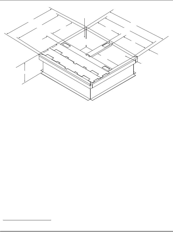
Figure 6: Roof Curb1
Ductwork
These units are adaptable to downflow use as well as rear supply and return air duct openings. To convert to downflow, use the following steps:
1.Remove the duct covers found in the bottom return and supply air duct openings. There are four (4) screws securing each duct cover (save these screws to use in Step 2).
2.Install the duct covers (removed in step one) to the rear supply and return air duct openings. Secure with the four
(4) screws used in step one.
3.Seal duct covers with silicone caulk.
Duct work should be designed and sized according to the methods of the Air Conditioning Contractors of America (ACCA), as set forth in their Manual D.
A closed return duct system shall be used. This shall not preclude use of economizers or ventilation air intake. Flexible joints may be used in the supply and return duct work to minimize the transmission of noise.
NOTE: Be sure to note supply and return openings.
Refer to Figures 4 and 5 for information concerning rear and bottom supply and return air duct openings.
Roof Curb
On applications when a roof curb is used, the unit must be positioned on the curb so the front of the unit is tight against the curb.
Filters
Single phase units are shipped without a filter or filter racks. It is the responsibility of the installer to secure a filter in the return air ductwork or install a Filter/Frame Kit (1FF0110).
A filter rack and high velocity filters are standard on three phase units.
Filters must always be used and must be kept clean. When filters become dirt laden, insufficient air will be delivered by the blower, decreasing your units efficiency and increasing operating costs and wear-and-tear on the unit and controls.
Filters should be checked monthly; this is especially important since this unit is used for both heating and cooling.
Condensate Drain
A condensate trap is recommended to be installed in the condensate drain. The plumbing must conform to local codes.
Use a sealing compound on male pipe threads. Install the condensate drain line (3/4” NPTF) to spill into an open drain.
1. 8” Roof Curb also available.
Unitary Products Group |
9 |
279550-YIM-A-0207
Service Access
Access to all serviceable components is provided at the following locations:
•Blower compartment access panel
•Gas control/electrical access panel
•Refrigerant connections
Refer to Figure 3 for location of these access locations and minimum clearances in Table 5.
This system uses R-410A Refrigerant which operates at higher pressures than R-22. No other refrigerant may be used in this system. Gage sets, hoses, refrigerant containers and recovery systems must be designed to handle R-410A. If you are unsure, consult the equipment manufacturer. Failure to use R-410A compatible servicing equipment may result in property damage or injury.
Wear safety glasses and gloves when handling refrigerants. Failure to follow this warning can cause serious personal injury.
Refer to Figure 20 for the R-410A Quick Reference Guide.
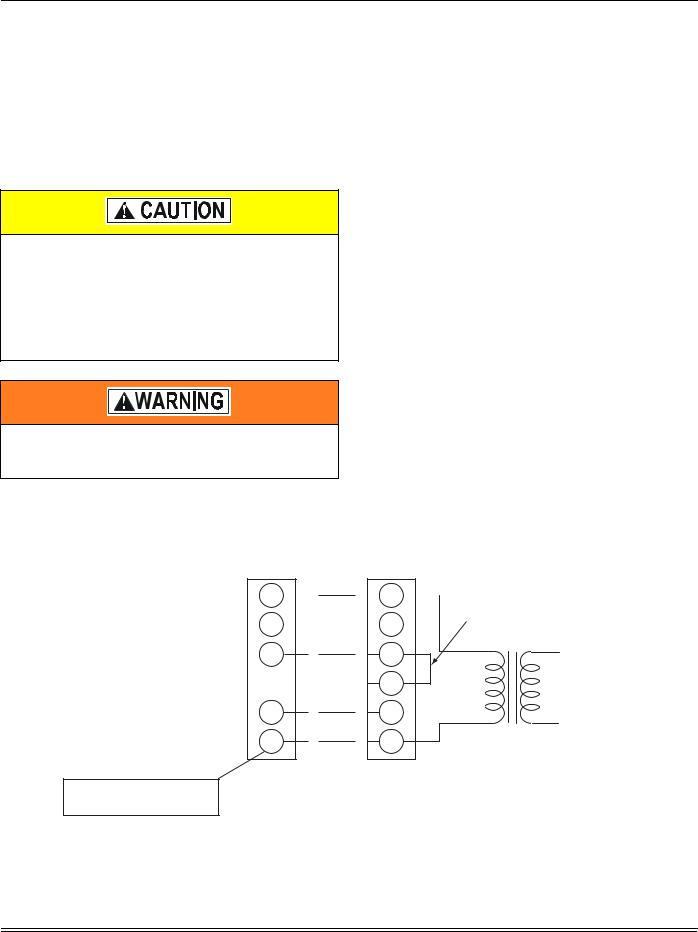
Thermostat
The room thermostat should be located on an inside wall approximately 56" above the floor where it will not be subject to drafts, sun exposure or heat from electrical fixtures or appliances. Follow manufacturer's instructions enclosed with the thermostat for general installation procedure. Color coded insulated wires (minimum #18 AWG) should be used to connect thermostat to unit. See Figures 7 thru 10.
Power And Control Wiring
Field wiring to the unit must conform to provisions of the current N.E.C. ANSI/NFPA No. 70 or C.E.C. and/or local ordinances. The unit must be electrically grounded in accordance with local codes or, in their absence, with the N.E.C./C.E.C. Voltage tolerances which must be maintained at the compressor terminals during starting and running conditions are indicated on the unit Rating Plate and Table 6.
The wiring entering the cabinet must be provided with mechanical strain relief.
A fused disconnect switch should be field provided for the unit. If any of the wire supplied with the unit must be replaced, replacement wire must be of the type shown on the wiring diagram.
Electrical line must be sized properly to carry the load. Each unit must be wired with a separate branch circuit fed directly from the meter panel and properly fused.
Refer to Figures 7 thru 11 for typical field wiring and to the appropriate unit wiring diagram for control circuit and power wiring information.
|
|
|
|
|
|
|
|
|
|
|
|
|
|
127( +($7 $17,&,3$725 |
|
6,1*/( 67$*( |
81,7 &21752/ %2$5' |
|
6+28/' %( 6(7 $7 |
|
|||||||||||
|
$036 )25 $// 02'(/6 |
|
|||||||||||||
|
7+(50267$7 |
|
|
7(50,1$/ 675,3 |
|
|
|
||||||||
0LQLPXP ZLUH VL]H RI $:* |
|
|
|
|
|
|
|||||||||
5 |
|
|
|
|
|
|
|
5 |
|
|
|
|
|
||
|
|
|
|
|
|
|
|
||||||||
ZLUH VKRXOG EH XVHG IRU DOO ILHOG |
|
|
|
|
|
|
|
|
|
|
|
|
-803(5 1(('(' )25 )8// 63((' |
||
LQVWDOOHG YROW ZLUH |
* |
|
|
|
|
|
|
|
* |
|
|
&2035(6625 23(5$7,21 |
|
||
|
|
|
|
|
|
||||||||||
< |
< |
|
|
< < |
92/7 |
|
|
75$16)250(5 |
: |
: |
|
&&
352*5$00$%/( 7+(50267$7 21/<
Figure 7: Typical Field Control Wiring Diagram Single Stage Thermostat - Single Stage Gas Heat
10 |
Unitary Products Group |
279550-YIM-A-0207
|
|
|
|
|
|
|
|
|
|
|
|
|
NOTE: HEAT ANTICIPATOR |
|
|
SINGLE STAGE |
UNIT CONTROL BOARD |
|
SHOULD BE SET AT 0.35 |
|
|||||||||
|
|
AMPS FOR ALL MODELS. |
|
|||||||||||
|
THERMOSTAT |
|
TERMINAL STRIP |
|
|
|||||||||
** = Minimum wire size of 18 AWG |
** |
|
|
|
||||||||||
R |
|
|
|
|
|
R |
|
|
|
|
|
|||
|
|
|
|
|
|
|||||||||
wire should be used for all field |
|
|
|
|
|
|
|
|
|
|
|
JUMPER NEEDED FOR FULL SPEED |
||
installed 24 volt wire. |
|
|
|
|
|
|
|
|
|
|
|
|||
G |
|
|
|
|
|
|
|
G |
COMPRESSOR OPERATION |
|||||
|
|
|
|
|
|
|
|
|||||||
Y |
Y1 |
Y/Y2
WW1
W2
C C
24 VOLT |
TRANSFORMER |
PROGRAMMABLE
THERMOSTAT ONLY
Figure 8: Typical Field Control Wiring Diagram Single Stage Thermostat - Two Stage Gas Heat
|
|
|
|
|
|
|
|
|
|
|
|
|
127( +($7 $17,&,3$725 |
|
67$*( |
81,7 &21752/ %2$5' |
6+28/' %( 6(7 $7 |
||||||||||
|
$036 )25 $// 02'(/6 |
||||||||||||
|
7+(50267$7 |
|
|
7(50,1$/ 675,3 |
|
||||||||
0LQLPXP ZLUH VL]H RI $:* |
|
|
|
|
|||||||||
5 |
|
|
|
|
|
|
|
5 |
|
|
|
||
|
|
|
|
|
|||||||||
ZLUH VKRXOG EH XVHG IRU DOO ILHOG |
|
|
|
|
|
|
|
|
|
|
|
|
|
LQVWDOOHG YROW ZLUH |
* |
|
|
|
|
|
|
|
* |
|
|
|
|
|
|
|
|
|
|
|
|
|
|
|
|||
< |
< |
|
< |
< < |
92/7 |
|
|
75$16)250(5 |
: |
: |
|
&&
352*5$00$%/( 7+(50267$7 21/<
Figure 9: Typical Field Control Wiring Diagram Two Stage Thermostat - Single Stage Gas Heat
Unitary Products Group |
11 |
Loading...