


B3CH 048
GENERAL
YORK Model BCH units are single package heat pumps
designed for outdoor installation on a rooftop or a slab.
Supplemental electric heaters are available as field-installed
accessories. The units are manufactured under ISO 9002
Quality System Certification.
Units are completely assembled on rigid, permanently
attachedbaserails.Allpiping,refrigerant charge, andelectrical
wiring is factory-installed and tested. The units require only
electricpowerandductconnectionsatthe point of installation.
The supplemental electric heaters have nickel-chrome
elements and utilize single point power connection.
INSPECTION
Assoonasaunit is received, itshouldbeinspectedforpossible
damage during transit. If damage is evident, the extent of the
damageshould be noted on thecarrier's freight bill. Aseparate
request for inspection by the carrier's agent should be made in
writing. See local distributor for additional information.
REFERENCE
Additional information on the design, installation, operation
and service of this equipment is available in the following
reference forms:
•
55.70-N1 -General Installation
•
55.70-N2 -Pre-start & Post-start Check List
•
530.18-N1.2V -Economizer Accessory
•
530.18-N1.4V -Fixed Outdoor Air Damper Accessory
•
530.18-N1.6V -Motorized Outdoor Air Damper Accy.
•
530.18-N7.1V -Electric Heater Accessory
• 530.18-N7.2V -Fuse Block Accessory
Renewal Parts:
•
Refer to Parts Manual for complete listing of replacement
parts on this equipment.
All forms referenced in this instruction may be ordered from:
Standard Register
Toll Free Tel: (405) 691-1126
Toll Free Fax: (405) 799-7746
APPROVALS
These units are designed and manufactured as follows:
1. For use as a heat pump only unit or a heat pump unit with
supplemental electric heat.
2. For outdoor installation only.
®
SUNLINE 2000
SINGLE PACKAGE HEAT PUMPS
INSTALLATION INSTRUCTION
Supersedes: 511.13-N1YI (900)/035-12984-000
035-12984-001-A-0204
Installershouldpay particular attentionto thewords: NOTE, CAUTIONand WARNING.Notes
areintended to clarifyor makethe
installation easier. Cautions
are given to prevent equipment damage. Warnings are given to alert installer that personal injury
and/or equipment damage may result if installation procedure is not handled properly.
MODELS B3CH 048 AND 060
(WORLD 50 HZ)
CAUTION
THE ENCLOSED INSTALLATION INSTRUCTIONS AND ANY APPLICABLE
LOCAL, STATE, AND NATIONAL CODES INCLUDING, BUT NOT LIMITED
TO, BUILDING, ELECTRICAL, AND MECHANICAL CODES.
TH IS P RO DU CT MU ST BE INS TAL LED IN STR IC T C O M P LIANCE W ITH
WARNING
OPERATION OF THE PRODUCT COULD CAUSE PERSONAL INJURY
OR PROPERTY DAMAGE.
INCORRECT INSTALLATION MAY CREATE A CONDITION WHERE THE
035-12984-001-A-0204
2 Unitary Products Group
General
................................................................................
1
Inspection
............................................................................
1
Reference
............................................................................
1
Approvals
............................................................................
1
Nomenclature
......................................................................
2
INSTALLATION
Limitations
...........................................................................
3
Location
...............................................................................
3
Condensate Drainage Precaution
.......................................
3
Rigging and Handling
..........................................................
3
Clearances
..........................................................................
3
Ductwork
.............................................................................
3
Filters
...................................................................................
4
Condensate Drain
...............................................................
4
Service Access
....................................................................
4
Blower Speed Selection
......................................................
4
Disconnect Switch Bracket For Optional Belt-Drive
............
4
Compressors
.......................................................................
4
Thermostat
..........................................................................
4
Power and Control Wiring
...................................................
4
Electric Heaters...................................................................4
Optional Economizer Rain Hood.........................................6
OPERATION
Cooling System .................................................................12
Preliminary Operation Cooling ..........................................12
Cooling Sequence of Operation ........................................12
Heating Sequence of Operation........................................12
Defrost Sequence of Operation.........................................12
Lockout Control
.................................................................
13
Checking Supply Airflow
....................................................
13
Secure Owner's Approval
..................................................
14
MAINTENANCE
Normal Maintenance
.........................................................
14
TABLES
No. Description Page
1 Unit Application Data
..................................
3
2 Air Flow Limitations
....................................
5
3 Physical Data
.............................................
7
4 Supply Air Perferformance — BCH048
......
10
5 Supply Air Performance — BCH060
..........
10
6 Motor and Drive Data - Belt-Drive Blower
..
10
7 Static Resistances
......................................
10
8 Electrical Data — Basic Unit
......................
11
9 Electrical Data — Heat Pump
....................
11
10 Belt-Drive Supply Air Motor Pulley Adj.
.......
13
FIGURES
No. Description Page
1 Center of Gravity........................................ 3
2 Recommended Drain Piping...................... 4
3 Typical Field Wiring.................................... 5
4 Economizer Rain Hood Assembly.............. 6
5 Adjusting Enthalpy Setpoint....................... 7
6 Dimensions and Clearances...................... 8 & 9
7 Defrost Initiation Times .............................. 12
8 Ambient Modified Time/Temp. Control....... 12
9 Belt Adjusment
...........................................
13
10 Hole Loc. for Press. Drop Readings
...........
13
11 Press. Drop versus Supply Airflow
.............
13
TABLE OF CONTENTS
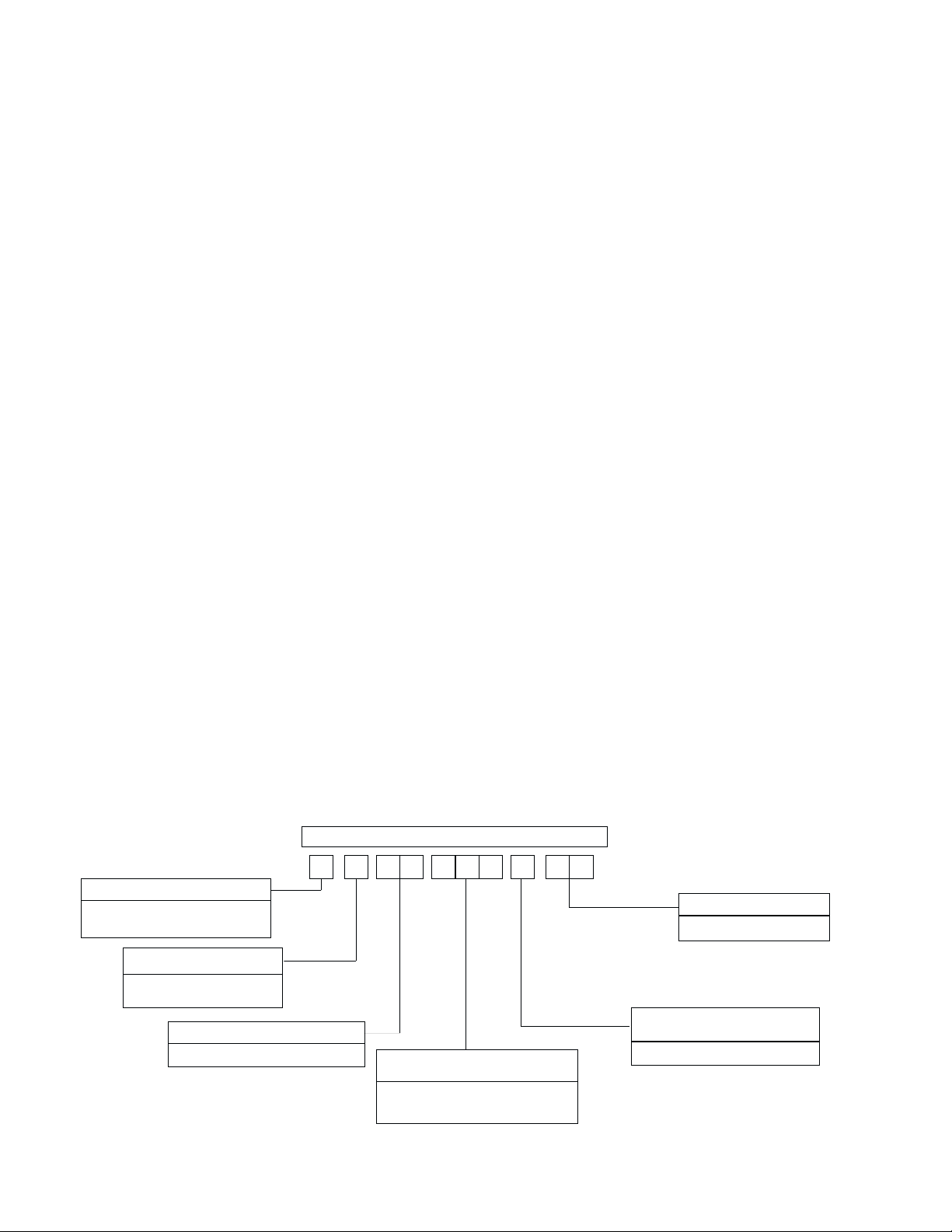
B 3 C H A
PRODUCT NOMENCLATURE
PRODUCT GENERATION
3 = Third Generation
PRODUCT CATEGORY
B = Single Package Heat Pump
(Air Cooled)
PRODUCT IDENTIFIER
CH = Heat Pump
VOLTAGE CODE
50 = 380/415-3+N-50
048 = 4 Ton
060 = 5 Ton
40 8 5 0
FACTORYINSTALLED HEAT
A = No Supplemental Heat
NOMINAL COOLING CAPACITY
LIMITATIONS
These units must be installed in accordance with national and
local or municiple safety codes: Refer to Table 1 for Unit
Application Data.
If components are to be added to a unit to meet local codes, they
aretobeinstalledatthedealer'sand / or the customer'sexpense.
LOCATION
Use the following guidelines to select a suitable location for
these units.
1. Unit is designed for outdoor installation only.
2. Outdoor coil must have an unlimited supply of air.
3. For ground level installation, use a level concrete slab with
a minimum thickness of 102mm (4 in.). The length and
widthshould be at least 152mm (6 in.) greater than the unit
base rails. Do not tie slab to the building foundation.
4. Roof structures must be able to support the weight of the unit
and its options and / or accessories. Unit must be installed on
a solid level roof curb or appropriate angle iron frame.
CAUTION: If a unit is to be installed on a roof curb or special frame
other than a YORK roof curb, gasketing must be applied
toallsurfacesthatcomeincontactwith the unit underside.
5. Maintain level tolerance to 13mm (
1
2
in.) maximum across
the entire length or width of the unit.
6. Elevate the unit sufficiently to prevent any blockage of the
airentrances by snowin areas wherethere will besnow ac
-
cumulation. Check the local weather bureau for the ex
-
pected snow accumulation in your area.
OUTDOORCOIL CONDENSATEDRAINAGE PRECAUTION
Condensatedrainsfromtheoutdoorcoil during theheatingand
defrost cycles. Normally this condensate may be allowed to
drain directly onto the ground/roof. A gravel bed is
recommended to prevent mud splashing.
WARNING:Theunit should notbe installed in an area wheremud
or ice could cause personal injury. Remember that
condensate drips from the outdoor coil during heat
and defrost cycles and that this condensate freezes
when the temperature of the outdoor air is below 0°C
(32
°
F).
RIGGING AND HANDLING
Exercise care when moving the unit. Do not remove any
packaginguntil the unitis near the place of installation. Rig the
unit by attaching chain or cable slings to the lifting holes
provided in the base rails. Spreaders, whose length exceeds
the largest dimension across the unit, MUST be used across
the top of the unit.
BEFORE LIFTING AUNIT,MAKE SURE THATITS WEIGHT
IS DISTRIBUTED EQUALLY ON THE CABLES SO THAT IT
WILL LIFT EVENLY.
Units may also be moved or lifted with a forklift. Slotted
openings in the base rails are provided for this purpose.
LENGTH OF FORKS MUST BE A MINIMUM OF 1067mm
(42 in.).
Remove the nesting brackets from the four corners on top of
the unit. All screws that are removed when taking these
brackets off must be replaced on the unit.
RefertoTable3forunitweightsandtoFigure 1 for approximate
center of gravity.
CLEARANCES
All units require certain clearances for proper operation and
service. Refer to Figure 6 for the clearances required for
combustibleconstruction,servicing,andproperunitoperation.
WARNING:Do not permit overhanging structures or shrubs to
obstruct outdoor air discharge outlet.
DUCTWORK
A closed return duct system shall be used. This does not
preclude use of economizers or outdoor fresh air intake. The
supply and return air duct connections at the unit should be
madewithflexiblejointstominimizethetransmission of noise.
Thesupply and return air duct systems should be designed for
theairflowandstatic requirements of thejob.Theyshould NOT
be sized to match the dimensions of the duct connections on
the unit.
CAUTION: When fastening ductwork to the side duct flanges
on the unit, insert the screws through the duct
flanges only. DO NOT insert the screws through
the casing.
Outdoor ductwork must be insulated and water
-
proofed.
Refer to Figure 6 for information concerning side and bottom
supply and return air duct openings.
FILTERS
Each unit is supplied with 25mm (1 in.) filters . Replacement
51mm (2 in.) filters may be used without modification to the
filter racks. Filters must always be installed ahead of the
evaporator coil and must be kept clean or replaced with same
035-12984-001-A-0204
Unitary Products Group 3
INSTALLATION
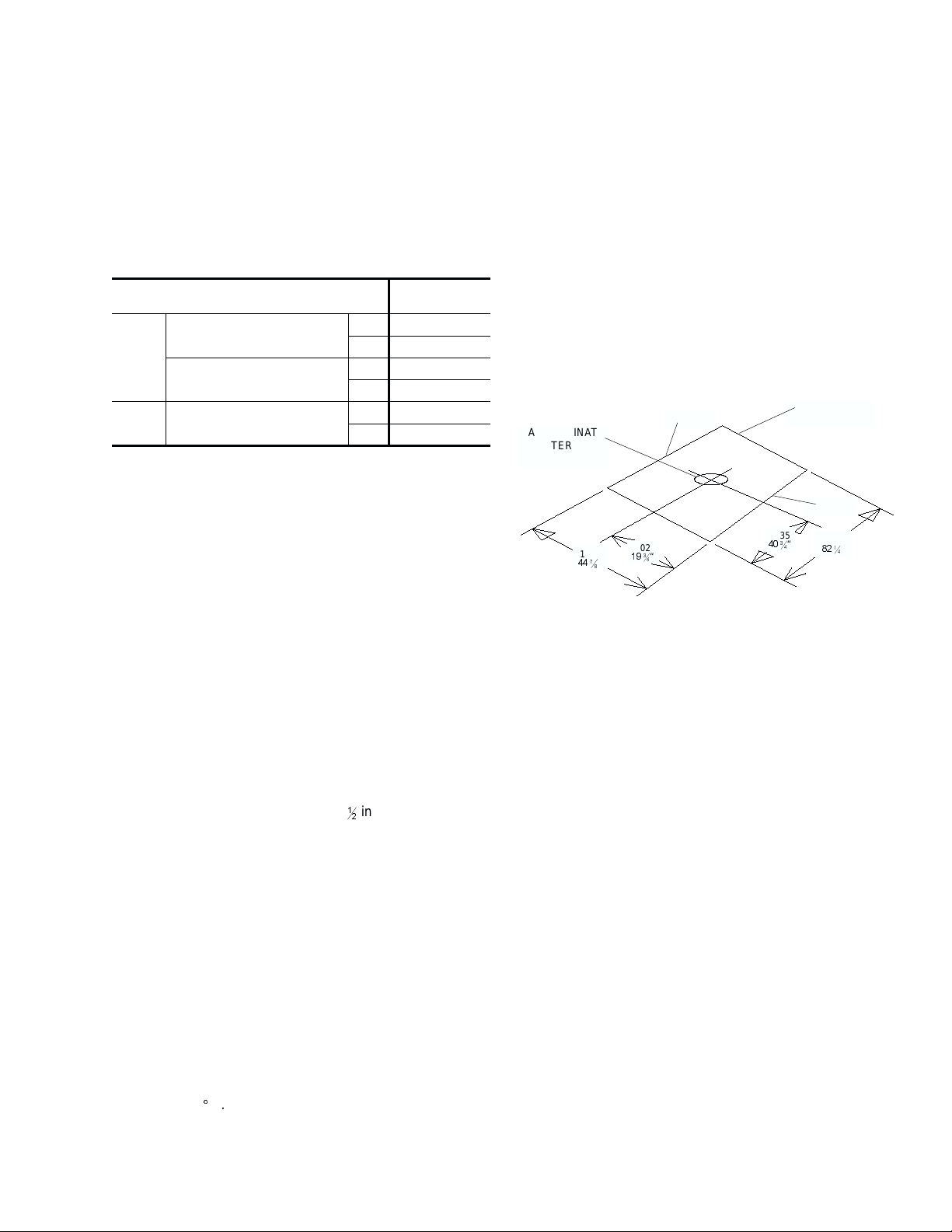
FIG. 1 - CENTER OF GRAVITY
2089
82
1
4
“
1035
40
3
4
“
1140
44
7
8
“
502
19
3
4
“
APPROXINATE
CENTER OF
GRAVITY
FRONT
BACK
CONDENSER
COIL END
Voltage Variation
Min. / Max.
342 / 457
Cooling
Wet Bulb Temperature of Air
on Indoor Coil, Min./Max.
°C 14 / 22
°F 57 / 72
Dry Bulb Temperature of Air
on Outdoor Coil, Min./Max.
°C 7 / 49
°F 45 / 120
Heating
Minimum Dry Bulb Temperature
of Air on Outdoor Coil
°C -23
°F -10
TABLE 1 - UNIT APPLICATION DATA

size and type. Dirty filters reduce the capacity of the unit and
result in frosted coils or safety shutdown. Minimum filter area
and required sizes are shown in Table 3.
CONDENSATE DRAIN
Plumbing must conform to local codes. Use a sealing
compound on male pipe threads. Install a condensate drain
linefromthe19mm(
3
4
in.)PVCfemaleconnectionon the unit to
spill into an open drain.
NOTE: The condensate drain line MUST be trapped to pro
-
vide proper drainage. See Figure 2.
SERVICE ACCESS
Access to all serviceable components is provided by the
following removable panels:
•
Compressor compartment
•
Heater compartment
•
Blower compartment
•
Main control box
•
Filter compartment
•
Motor Access (on units w/belt-drive option)
Refer to Figure 6 for location of these access panels.
BLOWER SPEED SELECTION
Threeblowermotor speeds areavailable on theBCH048 units.
The speed selection is determined by the airflow and ESP
requirements of the applications. BCH060 units have an
adjustable motor pulley to achieve the above conditions.
BCH048 units are shipped with the black wire (labeled #8)
connectedto the high speed tapon the blower motor.If a lower
blower speed is desired, this wire should be moved to the
medium or low speed tap on the motor.
DISCONNECT SWITCH BRACKET FOR UNITS
WITH OPTIONAL BELT-DRIVE BRACKET
A special bracket for mounting a field-supplied disconnect
switch is provided in each BCH060. The bracket is shipped
inside the blower compartment taped to the top of the blower
housing. Install the bracket on the left hand side of the unit as
shownin Figure6. Severalexisting screws at the top of the unit
and one approximately midway down from the top will be used
for mounting the bracket. Screws should be loosened only -
NOT REMOVED. Mounting holes in the bracket have
elongated keyways allowing easy installation. Re-tighten
screws after bracket is in place to ensure panels will remain
leak tight.
COMPRESSORS
On some units the compressor is mounted on springs which
have been tightened down for shipment only.
After this unit is installed, back out the compressor bolts until
the sleeve clears the top grommet.
CAUTION: Do Not
loosen compressor mounting bolts.
THERMOSTAT
The room thermostat should be located on an inside wall
approximately 1422mm (56 in.) above the floor where it is not
subjected to drafts, sun exposure, or heat from electrical
fixtures or appliances. Follow manufacturer's instructions
enclosed with thermostat for general installation procedure.
Color coded insulated wires (#18 AWG) should be used to
connect thermostat to unit. See Figure 3 for wiring details.
NOTE: On units with economizer, remove jumper “J1" from
terminals 8 and 10 on plug connector J3/P7 on the re
-
layboardin the unitcontrolbox. Refer totheunitwiring
labels located on the inside of the control box access
panel.
An “Emergency Heat” position is provided with the
thermostat.In the “Emergency Heat” position, the thermostat
allowselectricresistanceheatonly.The compressorislocked
out. Apilot light on the thermostat indicates that the switch is
on “EM HT”.
POWER AND CONTROL WIRING
Voltagetolerances which must be maintained at the compressor
terminals during starting and running conditions are indicated on
the unit Rating Plate and Table 1.
The wiring harness furnished with this unit is an integral partof
the unit. Field alteration to comply with electrical codes should
not be required.
A disconnect switch should be field provided for the unit. The
switch must be separate from all other circuits. Refer to Figure
6forinstallationlocation.If any of thewiresuppliedwith the unit
mustbe replaced, replacement wire must be of the typeshown
on the wiring diagram.
Electrical lines must be sized properly to carry the load. USE
COPPERCONDUCTORSONLY.Eachunit must bewired with
a separate branch circuit fed directly from the meter panel and
properly protected.
CAUTION: When connecting electrical power and control wir
-
ing to the unit, waterproof type connectors MUST
BE USED so that water or moisture cannot be
drawn into the unit during normal operation. The
above waterproofing conditions also apply when
installing a field-supplied disconnect switch.
Refer to Figure 3 for typical field wiring and to the appropriate
unit wiring diagram for control circuit and power wiring
information. Refer to Tables 8 and 9 for electrical data.
ELECTRIC HEATERS
Supplemental electric heaters may be ordered as a field-
installed accessory. Refer to Form 530.18-N7.1V for
installation instruction. These approved heaters are located
within the central compartment of the unit (see Figure 6 for
access panel) with the heating elements extending into the
supply air chamber.
Fuses are supplied, where required, by the factory. Some kW
sizes require fuses and others do not. Refer to the electric
035-12984-001-A-0204
4 Unitary Products Group
FIG. 2 - RECOMMENDED DRAIN PIPING
76
3"
51
2"
035-12984-001-A-0204
Unitary Products Group 5
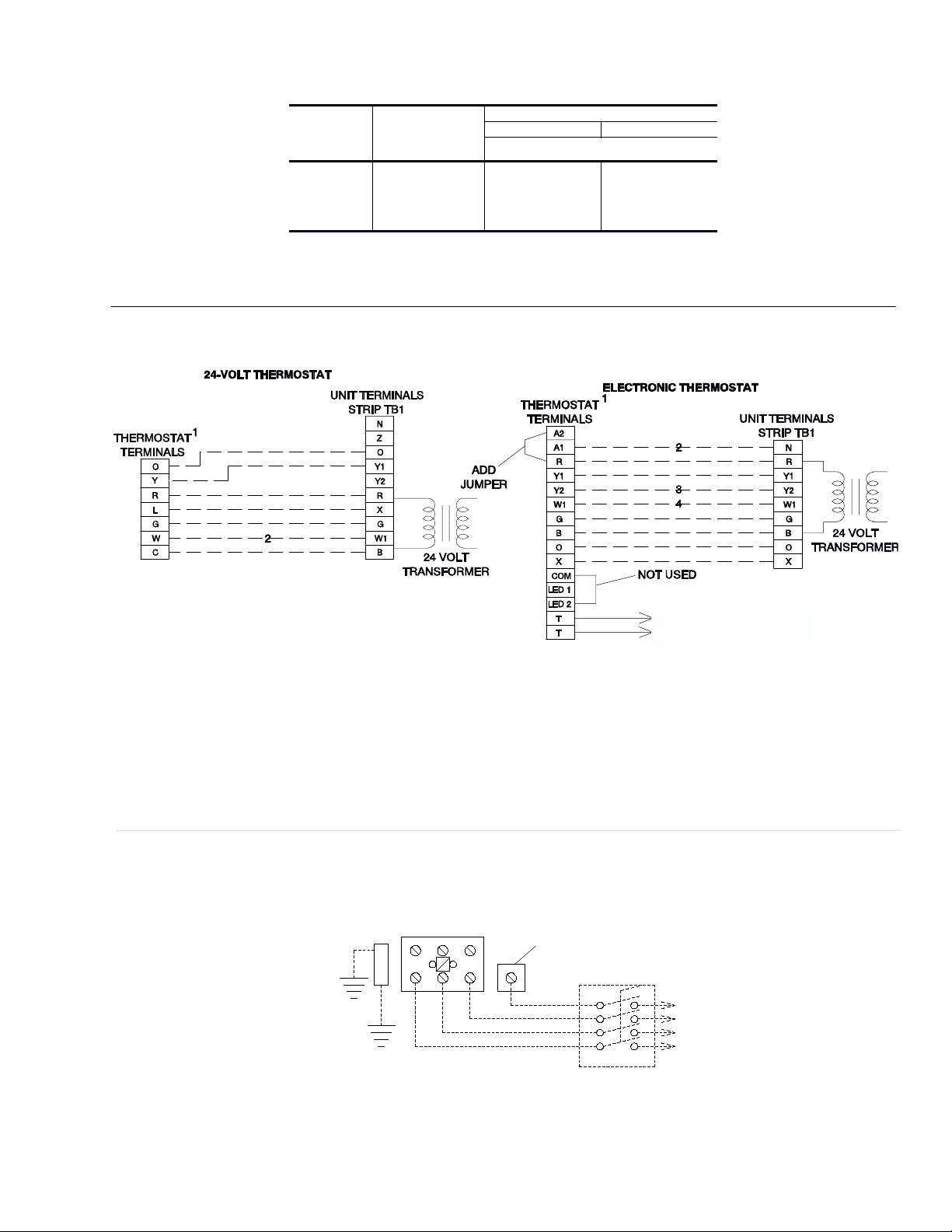
FIG. 3 - TYPICAL FIELD WIRING
CONTROL WIRING
POWER WIRING
NOMINAL
HEATER
SIZE
KW
VOLTAGE
UNIT MODEL SIZE, NOMINAL TONS
45
MINIMUM SUPPLYAIR CFM
7
10
15
20
30
380/415-3+N-50
1,300
1,300
1,300
1,300
–
1,600
1,600
1,600
1,600
1,600
TABLE 2 - AIR FLOW LIMITATIONS
TO REMOTE SENSOR
2ET04701324 IF USED
1 Typical 24-volt thermostat with subbase
-2ET03700424 for manual changeover.
2
Only required on units with supplemental electric heat.
1 Typical Electronic programmable thermostat 2ET04701124 with subbase for
either manual or automatic changeover.
2
Only required on units with economizer. Remove jumper L2 from terminals
4 and 9 on jumper plug P7. The outdoor air intake dampers will return to their
fully closed position when the thermostat switches to the “unoccupied” mode.
3
Second stage cooling may be used on units with economizer. Remove jumper
J1 from terminals 8 and 10 on jumper plug connector P7.
4
Only required on units with supplemental electric heat.
REFER TO ELECTRICAL DATA
TABLES TO SIZE THE DISCONNECT
SWITCH, THE WIRING AND THE
OVERCURRENT PROTECTION.
GROUND
LUG
NEUTRAL
TERMINAL
BLOCK
CONTACTOR
FIELD-SUPPLIED
DISCONNECT
Note: The thermostat terminals shown
above are typical. Check thermostat
and unit wiring diagrams for correct
wiring connections.
 Loading...