


®
TECHNICAL GUIDE
STELLAR 2000
SPLIT-SYSTEM AIR CONDITIONERS 10 SEER 50 HZ
MODELS: H*DA012 THRU H*DA076 (1 & 3 PHASE)
(1 THRU 7.5 NOMINAL TONS)
Due to continuous product improvement, specifications are subject to change without notice.
Visit us on the web at www.york.com for the most up-to-date technical information.
036-21105-004 Rev. A (0902)
DESCRIPTION
The HDA Series condensing unit is the outdoor part of a versatile system of air conditioning. It is designed to be custommatched with one of UPG's complete line of evaporator sections, each designed to serve a specific function. Matching Air Handlers are available for upflow, downflow or horizontal application to provide a complete system. Electric heaters are available if required.
FEATURES
•QUALITY CONDENSER COILS - The coil is constructed of enhanced copper tube and aluminum fins.
•COIL PROTECTION - Coils are protected from damage by a polymer mesh applied between the coil face, and a PVC coated steel coil guard.
•PROTECTED COMPRESSOR - The compressor is internally protected against high pressure and temperature. This is accomplished by the simultaneous operation of high pressure relief valve and a temperature sensor which protect the compressor if undesirable operating conditions occur.
•DURABLE FINISH - Cabinet is made of pre-painted steel. The pre-treated flat galvanized steel provides a better paint to steel bond, which resists corrosion and rust creep. Special primer formulas and glossy earth tone finish insure less fading when exposed to sunlight.
•LOWER INSTALLED COST - Installation time and costs are reduced by easy power and control wiring connections. Discharge line heat exchanger knockouts are provided, if required. Both quick connect and sweat connect models are available. Both service valves are firmly affixed to the unit. The sweat unit contains enough refrigerant for matching indoor coils and 15 feet of interconnecting piping. The small base dimension means less space is required on the ground or roof.
•TOP DISCHARGE - The warm air from the top mounted fan is blown up away from the structure and any landscaping. This allows compact location on multi-unit applications.
•LOW OPERATING SOUND LEVEL - The upward air flow carries the normal operating noise up away from the living area. The rigid top panel effectively isolates any motor sound. Isolator mounted compressor and the rippled fins of the condenser coil muffle the normal fan motor and compressor operating sounds.
•LOW MAINTENANCE - Long life permanently lubricated motorbearings need no annual servicing.
•EASY SERVICE ACCESS - Fully exposed refrigerant connections and a single panel covering the electrical controls make servicing easy.
•SECURED SERVICE VALVES - Secured re-usable service valves are provided on both the liquid and vapor sweat connections for ease of evacuating and charging.
•FACTORY TESTED - to verify system operation and control functioning before shipment.
FOR DISTRIBUTION USE ONLY - NOT TO BE USED AT POINT OF RETAIL SALE
036-21105-004 Rev. A (0902)
Physical and Electrical Data
MODEL H*DA |
|
18 |
24 |
30 |
36 |
48 |
|
60 |
076 |
||
|
|
|
|
|
|
|
|
|
|||
Unit Supply Voltage |
|
|
230 – 1 – 50 |
|
|
380/415 |
-3-50 |
|
|||
|
|
|
|
|
|
|
|
|
|||
Normal Voltage Range * |
|
216 to 252 |
|
|
|
342-456 |
|
||||
Minimum Circuit Ampacity |
12.4 |
16.2 |
18.4 |
8.1 |
12.0 |
|
12.7 |
20.2 |
|||
|
|
|
|
|
|
|
|
|
|
||
Max. Overcurrent Device Amps † |
20.0 |
25.0 |
30.0 |
15.0 |
20.0 |
|
20.0 |
30.0 |
|||
Compressor Type |
|
Recip |
Recip |
Recip |
Recip |
Recip |
|
Scroll |
Scroll |
||
|
|
|
|
|
|
|
|
|
|
|
|
Compressor Amps |
Rated Load |
9.2 |
12.2 |
13.4 |
5.8 |
7.5 |
|
9.5 |
14.7 |
||
|
|
|
|
|
|
|
|
|
|||
Locked Rotor |
53.0 |
72.0 |
85.0 |
39.0 |
62.0 |
|
73.0 |
95.0 |
|||
|
|
|
|
|
|
|
|
|
|
||
Crankcase Heater |
|
No** |
No** |
Yes |
Yes |
Yes |
|
No** |
No** |
||
|
|
|
|
|
|
|
|
|
|
|
|
Fan Motor Amps |
Rated Load |
0.9 |
0.9 |
1.4 |
0.8 |
0.8 |
|
0.8 |
1.0 |
||
|
|
|
|
|
|
|
|
|
|||
Locked Rotor |
1.4 |
1.4 |
3.12 |
1.8 |
1.8 |
|
2.0 |
1.8 |
|||
|
|
|
|
||||||||
|
|
|
|
|
|
|
|
|
|
||
Fan Diameter Inches |
18 |
18 |
18 |
18 |
18 |
|
24 |
24 |
|||
|
|
|
|
|
|
|
|
|
|
|
|
|
|
|
Rated HP |
1/8 |
1/8 |
1/4 |
1/4 |
1/4 |
|
1/4 |
1/3 |
|
|
|
|
|
|
|
|
|
|
|
|
Fan Motor |
|
Nominal RPM |
1075 |
1075 |
1100 |
1075 |
1075 |
|
850 |
940 |
|
|
|
|
|
|
|
|
|
|
|
|
|
|
|
|
Rated Voltage |
230 |
230 |
230 |
460 |
460 |
|
460 |
415 |
|
|
|
|
|
|
|
|
|
|
|
|
|
|
Face Area Sq. Ft. |
9.4 |
9.4 |
11.3 |
11.3 |
14.1 |
|
20 |
20.0 |
|
|
|
|
|
|
|
|
|
|
|
|
|
Coil |
|
Rows Deep |
1 |
1 |
1 |
1 |
1 |
|
1 |
2 |
|
|
|
|
|
|
|
|
|
|
|
|
|
|
|
Fin / Inches |
16 |
16 |
20 |
20 |
16 |
|
18 |
13 |
|
|
|
|
|
|
|
|
|
|
|
|
|
Liquid Line OD |
|
3/8 |
3/8 |
3/8 |
3/8 |
3/8 |
|
3/8 |
1/2 |
||
|
|
|
|
|
|
|
|
|
|
||
Vapor Line OD |
|
5/8 |
5/8 |
3/4 |
3/4 |
7/8 |
|
7/8 |
1-1/8 |
||
|
|
|
|
|
|
|
|
|
|||
Operating Weight Lbs. |
124 |
134 |
135 |
140 |
176 |
|
210 |
285 |
|||
|
|
|
|
|
|
|
|
|
|
|
|
*. Rated in accordance with ARI Standard 110, utilization range “A”. †. Dual element fuses or HACR circuit breaker.
** No crankcase heat required due to the compressor’s high pressure housing and internal design.
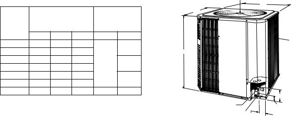
All dimensions are in inches. They are subject to change without
notice. Certified dimensions will be provided upon request. |
48" OVERHEAD |
|||||
CLEARANCE |
||||||
|
|
|
|
|
|
C |
|
|
|
|
Refrigerant |
B |
|
Unit |
Dimensions |
|
||||
Connection |
|
|||||
Model |
|
(Inches) |
|
Line Size |
|
|
H*DA |
A |
B |
C |
Liquid |
Vapor |
|
|
|
|||||
018 |
20-1/8 |
24 |
24 |
|
|
AIR IN |
|
5/8 |
4 SIDES |
||||
024 |
20-1/8 |
24 |
24 |
|
|
|
|
|
A |
||||
030 |
24-1/8 |
24 |
24 |
3/8 |
3/4 |
|
036 |
24-1/8 |
24 |
24 |
|
||
|
|
|
||||
048 |
30-1/8 |
24 |
24 |
|
7/8 |
|
060 |
31-1/8 34-1/2 |
34-1/2 |
|
|
||
|
|
|
||||
076 |
34-1/2 |
34-1/2 |
31-7/8 |
1/2 |
1-1/8 |
|
|
5-1/2 |
VAPOR |
|
CONNECTION |
2-3/8 |
LIQUID CONNECTION |
|
|
3-1/8 |
2 |
Unitary Products Group |
036-21105-004 Rev. A (0902)
COOLING PERFORMANCE
|
SUCT.T/P @ COMPR. |
|
|
|
|
AIR TEMP ON CONDENSER |
|
|
|
|
|||||
MODEL |
|
|
75 °F |
|
95°F |
115°F |
|
|
125°F |
||||||
|
|
|
|
|
|
|
|||||||||
|
TEMP |
PSIG |
MBH |
|
KW |
MBH |
|
KW |
MBH |
|
KW |
MBH |
|
KW |
|
|
35 |
61.5 |
|
13.0 |
|
1.31 |
10.9 |
|
1.41 |
9.0 |
|
1.53 |
8.0 |
|
1.59 |
H3DA012 |
40 |
68.5 |
|
14.5 |
|
1.36 |
12.3 |
|
1.49 |
10.2 |
|
1.62 |
9.1 |
|
1.69 |
45 |
76.0 |
|
16.1 |
|
1.41 |
13.7 |
|
1.54 |
11.3 |
|
1.69 |
10.1 |
|
1.76 |
|
|
|
|
|
|
|
||||||||||
|
50 |
84.0 |
|
17.7 |
|
1.44 |
15.2 |
|
1.58 |
12.4 |
|
1.74 |
11.1 |
|
1.82 |
|
35 |
61.5 |
|
18.7 |
|
1.83 |
15.6 |
|
1.99 |
12.5 |
|
2.09 |
10.9 |
|
2.13 |
H3DA018 |
40 |
68.5 |
|
20.8 |
|
1.90 |
17.6 |
|
2.07 |
14.3 |
|
2.20 |
12.6 |
|
2.24 |
45 |
76.0 |
|
22.9 |
|
1.97 |
19.6 |
|
2.17 |
16.2 |
|
2.31 |
14.5 |
|
2.37 |
|
|
|
|
|
|
|
||||||||||
|
50 |
84.0 |
|
25.2 |
|
2.05 |
21.8 |
|
2.27 |
18.3 |
|
2.43 |
16.5 |
|
2.49 |
|
35 |
61.5 |
|
21.9 |
|
2.34 |
18.7 |
|
2.54 |
15.6 |
|
2.71 |
14.0 |
|
2.77 |
H3DA024 |
40 |
68.5 |
|
24.3 |
|
2.41 |
20.9 |
|
2.63 |
17.6 |
|
2.84 |
15.9 |
|
2.91 |
45 |
76.0 |
|
26.7 |
|
2.47 |
23.2 |
|
2.73 |
19.7 |
|
2.97 |
18.0 |
|
3.06 |
|
|
|
|
|
|
|
||||||||||
|
50 |
84.0 |
|
29.3 |
|
2.53 |
25.6 |
|
2.82 |
21.9 |
|
3.10 |
20.0 |
|
3.20 |
|
35 |
61.5 |
|
27.6 |
|
2.64 |
23.9 |
|
2.88 |
20.2 |
|
3.11 |
18.3 |
|
3.20 |
H3DA030 |
40 |
68.5 |
|
30.4 |
|
2.71 |
26.5 |
|
2.99 |
22.5 |
|
3.24 |
20.5 |
|
3.34 |
45 |
76.0 |
|
33.3 |
|
2.78 |
29.2 |
|
3.08 |
25.0 |
|
3.37 |
22.8 |
|
3.48 |
|
|
|
|
|
|
|
||||||||||
|
50 |
84.0 |
|
36.3 |
|
2.85 |
31.9 |
|
3.18 |
27.5 |
|
3.49 |
25.5 |
|
3.62 |
|
35 |
61.5 |
|
33.6 |
|
3.07 |
28.8 |
|
3.43 |
24.0 |
|
3.82 |
21.6 |
|
4.01 |
H3DA036 |
40 |
68.5 |
|
37.3 |
|
3.09 |
32.1 |
|
3.48 |
26.9 |
|
3.88 |
24.3 |
|
4.08 |
45 |
76.0 |
|
40.9 |
|
3.23 |
35.2 |
|
3.69 |
30.2 |
|
4.13 |
27.5 |
|
4.36 |
|
|
|
|
|
|
|
||||||||||
|
50 |
84.0 |
|
44.8 |
|
3.37 |
39.1 |
|
3.85 |
33.3 |
|
4.35 |
30.4 |
|
4.60 |
|
35 |
61.5 |
|
46.7 |
|
3.87 |
39.1 |
|
4.82 |
31.9 |
|
57.8 |
28.3 |
|
6.39 |
H3DA048 |
40 |
68.5 |
|
51.7 |
|
4.07 |
43.5 |
|
5.08 |
35.7 |
|
6.14 |
31.8 |
|
6.83 |
45 |
76.0 |
|
56.8 |
|
4.28 |
48 |
|
5.34 |
39.6 |
|
6.51 |
35.4 |
|
7.28 |
|
|
|
|
|
|
|
||||||||||
|
50 |
84.0 |
|
62 |
|
4.49 |
52.7 |
|
5.6 |
43.7 |
|
6.89 |
39.2 |
|
7.73 |
|
35 |
61.5 |
|
53.8 |
|
5.16 |
48.7 |
|
6.09 |
43.4 |
|
7.25 |
40.8 |
|
7.92 |
H3DA060 |
40 |
68.5 |
|
58.9 |
|
5.33 |
53.1 |
|
6.25 |
47.5 |
|
7.41 |
44.7 |
|
8.08 |
45 |
76.0 |
|
64.1 |
|
5.51 |
57.8 |
|
6.43 |
51.8 |
|
7.58 |
48.7 |
|
8.25 |
|
|
|
|
|
|
|
||||||||||
|
50 |
84.0 |
|
69.6 |
|
5.71 |
62.5 |
|
6.61 |
56.1 |
|
7.76 |
52.9 |
|
8.43 |
|
35 |
61.5 |
|
73.9 |
|
5.55 |
66.2 |
|
6.60 |
58.3 |
|
7.98 |
54.4 |
|
8.82 |
H3DA076 |
40 |
68.5 |
|
80.7 |
|
5.69 |
72.5 |
|
6.75 |
64.3 |
|
8.14 |
60.2 |
|
8.98 |
45 |
76.0 |
|
87.7 |
|
5.84 |
79.1 |
|
6.91 |
70.5 |
|
8.30 |
66.2 |
|
9.15 |
|
|
|
|
|
|
|
||||||||||
|
50 |
84.0 |
|
95.1 |
|
5.99 |
86.1 |
|
7.07 |
76.9 |
|
8.48 |
72.4 |
|
9.32 |
NOTES:
1.For condensing unit only. Does not include effect of evaporator motor power or heat.
2.Performance based on 15° superheat and 15° sub-cooling at condensing unit.
a.Increase capacity 1% for each 2° increase in sub-cooling.
b.Decrease capacity 1% for each 2° decrease in sub-cooling.
3.Sub-cooling in excess of 20° may result in excessively high condensing temperature with air on condenser above 115°F. Maximum recommended condensing temperature is 140°F.
SOUND RATINGS
H*DA |
SOUND RATING |
MODEL |
DECIBELS |
|
|
H3DA012 |
7.8 |
H3DA018 |
7.8 |
H3DA024 |
7.8 |
H3DA030 |
7.8 |
H3DA036 |
7.8 |
H3DA048 |
8.0 |
H3DA060 |
8.2 |
H3DA076 |
8.2 |
ACCESSORIES
Refer to Price Manual for specific model numbers.
Off Cycle Timer - Provides a 5 minute off cycle to prevent rapid recycling of the compressor.
Room Thermostats - A wide selection of matching thermostats is available to provide features required for any installation.
Start Assist Kit - Provides increased starting torque for areas with low voltage conditions.
Compressor Blanket - Designed to further reduce the normal operating sounds of H3DA units.
Unitary Products Group |
3 |
 Loading...