


 Loading...
Technical Guide
SPLIT-SYSTEM
EVAPORATOR BLOWERS
K2EU060, K4EU090, K3EU120 &
K3EU180
5 THRU 15 NOMINAL TONS
036-21300-002-A-0905
DESCRIPTION
®These completely assembled units include a well-insulated cabinet, a DX cooling coil with copper tubes and aluminum fins, expansion valve(s), distributor(s), throwaway filters, a centrifugal blower, a blower motor, an adjustable belt drive, a blower motor contactor and a small holding charge of refrigerant-22.
The units are shipped in the vertical position ready for field installation. They can be installed for horizontal operation by reversing the position of the solid bottom panel with the return air duct flange on the front of the unit.
ACCESSORIES—FIELD INSTALLED
SUPPLY AIR PLENUMS
These fully insulated plenums are available for free standing units located within the conditioned space, are shipped knocked-down for easy field assembly, are finished to match the exterior of the basic unit, and have double deflection grills that can be adjusted to vary the throw, spread and drop of the supply air.
RETURN AIR GRILLS
These expanded metal grills are available for free standing units located within the conditioned space, are finished to match the exterior of the basic unit and are shipped in one piece for easy installation.
BASES
Bases are available to raise vertical units above the floor. Outdoor air may be introduced through these bases by cutting an access opening to accommodate the outdoor air duct connection. These bases are finished to match the exterior of the basic unit. They may have to be insulated in the field for certain applications.
THREE-PHASE ELECTRIC HEATERS
Electric heaters are available in several capacities to provide maximum flexibility. Both the air conditioning unit and the heater can be selected to precisely match the cooling and heating requirements of the conditioned space. These heaters are designed for easy field installation over the supply air opening of the unit. They have been tested by and will be shipped with a CSA label. Every heater will be fully protected against excessive current and temperature by fuses and two high limit thermostats.
Units with electric heat will require only one power supply for both the heating elements and the supply air blower motor, and the power wiring can be protected by either dual element/time delay fuses or an inverse time circuit breaker.
FOR DISTRIBUTION USE ONLY - NOT TO BE USED AT POINT OF RETAIL SALE
036-21300-002-A-0905
TABLE OF CONTENTS
DESCRIPTION . . . . . . . . . . . . . . . . . . . . . . . . . . . . . . . . . . . 1 ACCESSORIES—FIELD INSTALLED . . . . . . . . . . . . . . . . 1 NOMENCLATURE . . . . . . . . . . . . . . . . . . . . . . . . . . . . . . . . 3 APPLICATION FLEXIBILITY . . . . . . . . . . . . . . . . . . . . . . . 3
|
LIST OF FIGURES |
|
Fig. # |
Pg. # |
|
1 |
VERTICAL AND HORIZONTAL APPLICATION |
|
|
KEU060, 090 & 120 . . . . . . . . . . . . . . . . . . . . . . . . |
. . . 4 |
2 |
VERTICAL AND HORIZONTAL APPLICATION |
|
|
KEU180 . . . . . . . . . . . . . . . . . . . . . . . . . . . . . . . . . |
. . . 4 |
3 |
SUSPENSION MOUNTING (HORIZONTAL) - |
|
|
KEU060, 090 AND 120 . . . . . . . . . . . . . . . . . . . . . |
. . . 5 |
4 |
SUSPENSION ACCESSORY (HORIZONTAL) - |
|
|
KEU180 . . . . . . . . . . . . . . . . . . . . . . . . . . . . . . . . . |
. . . 6 |
5 |
UNIT DIMENSIONS KEU060 . . . . . . . . . . . . . . . . |
. . 16 |
6 |
UNIT DIMENSIONS KEU090 & 120 . . . . . . . . . . . |
. . 17 |
7 |
UNIT DIMENSIONS KEU180 . . . . . . . . . . . . . . . . |
. . 18 |
8 |
ACCESSORY DIMENSIONS . . . . . . . . . . . . . . . . |
. . 19 |
9 |
RETURN AIR GRILL . . . . . . . . . . . . . . . . . . . . . . . |
. . 20 |
10 |
BASE ACCESSORY . . . . . . . . . . . . . . . . . . . . . . . |
. . 20 |
11 |
STEAM COIL . . . . . . . . . . . . . . . . . . . . . . . . . . . . . |
. . 21 |
12 |
HOT WATER COIL . . . . . . . . . . . . . . . . . . . . . . . . |
. . 21 |
13 |
FIELD WIRING FOR POWER SUPPLY . . . . . . . . |
. . 24 |
14 |
COOLING ONLY UNIT . . . . . . . . . . . . . . . . . . . . . |
. . 24 |
15 |
UNIT WITH STEAM OR HOT WATER COIL |
|
|
ACCESSORY . . . . . . . . . . . . . . . . . . . . . . . . . . . . |
. . 24 |
16 |
FIELD WIRING FOR UNITS WITH ELECTRIC |
|
|
HEAT . . . . . . . . . . . . . . . . . . . . . . . . . . . . . . . . . . . |
. . 25 |
LIST OF TABLES
Tbl. # |
Pg. # |
|
1 |
UNIT SUSPENSION MOUNTING (HORIZONTAL |
|
|
APPLICATION) WEIGHTS . . . . . . . . . . . . . . . . . . |
. . . 5 |
2 |
KEU OPERATING WEIGHTS (LBS.) . . . . . . . . . . |
. . . 5 |
3 |
SOUND POWER RATINGS . . . . . . . . . . . . . . . . . |
. . . 6 |
4 |
HEATING CAPACITY - ELECTRIC HEAT |
|
|
ACCESSORY . . . . . . . . . . . . . . . . . . . . . . . . . . . . |
. . . 7 |
5 |
STEAM COIL CAPACITY, MBH@2 PSIG . . . . . . |
. . . 8 |
6 |
HOT WATER CAPACITY, MBH . . . . . . . . . . . . . . |
. . . 8 |
7 |
PRESSURE DROP VS. GPM . . . . . . . . . . . . . . . . |
. . . 8 |
8 |
CAPACITY CORRECTION VS. GPM . . . . . . . . . . |
. . . 8 |
9 |
SUPPLY AIR BLOWER PERFORMANCE - |
|
|
KEU060 (5 TON) . . . . . . . . . . . . . . . . . . . . . . . . . . |
. . . 9 |
10 |
SUPPLY AIR BLOWER PERFORMANCE - |
|
|
KEU090 (7.5 TON) . . . . . . . . . . . . . . . . . . . . . . . . |
. . 10 |
11 |
SUPPLY AIR BLOWER PERFORMANCE - |
|
|
KEU120 (10 TON) . . . . . . . . . . . . . . . . . . . . . . . . . |
. . 11 |
12 |
SUPPLY AIR BLOWER PERFORMANCE - |
|
|
KEU180 (15 TON) . . . . . . . . . . . . . . . . . . . . . . . . . |
. . 12 |
13 |
STATIC RESISTANCE FOR UNIT ACCESSORIES |
|
|
(IWG) - KEU060-120 . . . . . . . . . . . . . . . . . . . . . . . |
. . 13 |
14 |
STATIC RESISTANCE FOR UNIT ACCESSORIES |
|
|
(IWG) - KEU180 . . . . . . . . . . . . . . . . . . . . . . . . . . |
. . 13 |
15 |
SUPPLY AIR PLENUM PERFORMANCE DATA . |
. . 14 |
16 |
BLOWER MOTOR AND DRIVE DATA . . . . . . . . . |
. . 14 |
17 |
KEU PHYSICAL DATA . . . . . . . . . . . . . . . . . . . . . |
. . 15 |
18 |
UNIT CLEARANCES KEU060 . . . . . . . . . . . . . . . |
. . 16 |
19 |
UNIT CLEARANCES KEU090 & 120 . . . . . . . . . . |
. . 17 |
20 |
UNIT CLEARANCES KEU180 . . . . . . . . . . . . . . . |
. . 18 |
21 |
ELECTRIC HEATER DIMENSIONS KEU060, 090, |
|
|
120 & 180 . . . . . . . . . . . . . . . . . . . . . . . . . . . . . . . |
. . 20 |
22 |
KEU ELECTRICAL DATA . . . . . . . . . . . . . . . . . . . |
. . 22 |
2 |
Unitary Products Group |
036-21300-002-A-0905
NOMENCLATURE
<RUN ,QGRRU 6SOLW 6\VWHP 3URGXFW 1RPHQFODWXUH
. (8 $
3URGXFW &DWHJRU\
. $LU +DQGOHU 6SOLW 6\VWHP$&
3URGXFW *HQHUDWLRQ
)RXUWK *HQHUDWLRQ
3URGXFW ,GHQWLILHU
(8 5 6WDQG (II 3LSH
1RPLQDO &RROLQJ
&DSDFLW\ 0%+
7RQ7RQ7RQ7RQ
9ROWDJH &RGH
+HDW 7\SH 1RPLQDO +HDW &DSDFLW\
$ &RROLQJ 2QO\ 6XLWDEOH IRU ILHOG LQVWDOOHG HOHFWULF KHDW
ACCESSORIES-FIELD INSTALLED (CONT.)
HOT WATER COILS
These drainable coils have 2 rows of 1/2" copper tubes, 12 aluminum fins per inch, a casing that is finished to match the exterior of the basic unit, but no water control valve. The coils slide out of their casings for easy field installation. They should be mounted over the return air opening on 5, 7-1/2 and 10-ton units—between the unit coil and blower sections on 15-ton units.
STEAM COILS
These non-freeze coils have 1 row of 1" copper tubes, a 5/8" copper tube inside each 1" tube to distribute the steam evenly across the entire length of the coil, 8 aluminum fins per inch, a casing that is finished to match the exterior of the basic unit, but no steam control valve. The coils slide out of their casings for easy field installation and are pitched in their casings to facilitate condensate drainage. They should be mounted over the return air opening on 5, 7-1/2 and 10-ton units—between the unit coil and blower sections on 15-ton units.
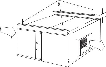
SUSPENSION KIT
Suspension kit 1HH0451 is available for 15-ton units installed horizontally. The accessory includes two channel iron supports and the hardware to secure them to the top of the unit. The hanger rods must be supplied by the field.
THERMOSTATS
Wall-mounted thermostats and subbases (24-volt) with system and fan switches are available to control the operation of these split system air conditioners.
APPLICATION FLEXIBILITY
MODELS 5, 7-1/2 & 10 TON
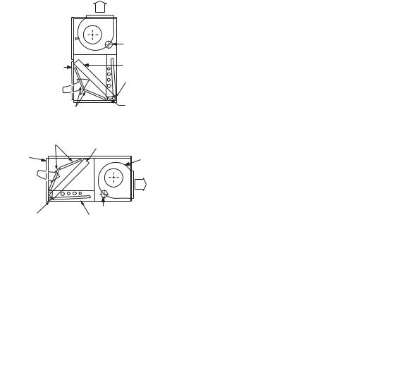
These units are built in a single cabinet with two condensate drain pans. This allows the units to be installed in either the vertical or horizontal position for maximum flexibility.
On vertical applications, the air velocity across the cooling coil keeps the condensate from dripping off the finned surface onto the filters.
On horizontal applications, the unit must be installed with the condensate drain pan under the entire cooling coil.
•The Supply Air Plenum and the Return Air Grill accessories can be used on either arrangement.
•The Base accessory can only be used on the vertical arrangement.
Units installed horizontally are designed for ceiling suspension. Four 3/8"-16 weld nuts are provided in the angle supports on the front of the unit (the side with the logo). Knockouts are provided in the exterior panels for access to these weld nuts. The hanger rods must be supplied in the field.
Unitary Products Group |
3 |
$,5 287
%/2:(5 %/2:(5 02725
5(7851 $,5 |
&2,/ |
|
'8&7 )/$1*( |
||
&21'(16$7( |
||
|
||
$,5 |
'5$,1 |
|
&211(&7,21 |
||
,1 |
||
|
||
|
&21'(16$7( |
|
),/7(56 |
'5$,1 3$1 |
|
9(57,&$/ 326,7,21 |
||
),/7(56 |
&2,/ |
|
5(7851 |
||
|
||
$,5 '8&7 |
%/2:(5 |
|
)/$1*( |
||
|
||
$,5 |
|
|
,1 |
$,5 |
|
|
287 |
|
&21'(16$7( |
%/2:(5 02725 |
|
'5$,1 &211(&7,21 &21'(16$7( '5$,1 3$1
+25,=217$/ 326,7,21
FIGURE 1 - VERTICAL AND HORIZONTAL APPLICATION KEU060, 090 & 120
036-21300-002-A-0905
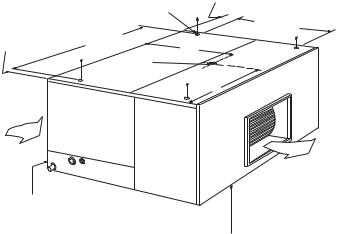
MODEL 15 TON
These units have two distinct modules . . . a blower module and a coil module. Although the unit is always shipped in the vertical position with a vertical air discharge as shown in illustration (a), the blower module can be repositioned in the field as shown in illustrations (b) and (c) for maximum flexibility.
•The Supply Air Plenum, Return Air Grill and Base accessories can be applied on arrangement (a).
•The Return Air Grill and Base accessories can be applied on arrangement (b).
•The Supply Air Plenum, Return Air Grill and Suspension accessories can be applied on arrangement (c).
9(57,&$/ 326,7,21 |
+25,=217$/ 326,7,21 |
FIGURE 2 - VERTICAL AND HORIZONTAL APPLICATION KEU180
4 |
Unitary Products Group |
036-21300-002-A-0905
|
|
|
|
|
|
|
:(/' 18876 |
$ |
|
|
|
|
+%5 |
|
|
|
|
|
+%5 |
|
+%5 |
|
|
% |
.(8 |
+%5 |
|
|
|
|
|
; |
|
|
.(8 |
' |
&(17(5 |
|
|
|
|
|
||
|
|
|
|
|
|
|
2) *5$9,7< |
|
|
&
<
!)2
).
!)2 /54
5(7851 $,5 *5,// +27 :$7(5 &2,/ $1' 67($0 &2,/ $&&(6625,(6 ,167$//(' 217+,6 (1' 2) 7+( 81,7
6833/< $,5 3/(180 $1' (/(&75,& +($7(5 $&&(6625,(6 ,167$//(' 21 7+,6 (1' 2) 7+( 81,7
FIGURE 3 - SUSPENSION MOUNTING (HORIZONTAL) - KEU060, 090 AND 120
TABLE 1: UNIT SUSPENSION MOUNTING (HORIZONTAL APPLICATION) WEIGHTS
|
Shipping |
Operating |
|
CG (in) |
|
4-Point Loading (lb) |
|
||||
Unit Model |
Weight |
Weight |
X |
|
Y |
A |
|
B |
C |
|
D |
|
(lb) |
(lb) |
|
|
|
||||||
|
|
|
|
|
|
|
|
|
|
||
K*EU060 |
225 |
210 |
22.50 |
|
15.00 |
47 |
|
51 |
58 |
|
53 |
K*EU090 |
340 |
235 |
26.50 |
|
24.00 |
78 |
|
84 |
84 |
|
78 |
K*EU120 |
370 |
355 |
26.50 |
|
24.00 |
86 |
|
92 |
92 |
|
86 |
K*EU180 |
440 |
425 |
26.50 |
|
24.00 |
104 |
|
77 |
104 |
|
141 |
TABLE 2: KEU OPERATING WEIGHTS (LBS.)
|
MODEL |
|
060 |
090 |
|
120 |
180 |
|
BASIC UNIT |
(Cooling Only) |
|
210 |
325 |
|
325 |
425 |
|
|
Base |
|
45 |
55 |
|
55 |
65 |
|
|
Return Air Grill |
|
10 |
15 |
|
15 |
20 |
|
|
Supply Air Plenum |
|
90 |
100 |
|
100 |
115 |
|
|
Hot Water Coil |
|
70 |
105 |
|
105 |
135 |
|
ACCESSORIES |
Steam Coil |
|
80 |
115 |
|
115 |
145 |
|
|
|
10 KW |
|
|
66 |
|
||
|
|
|
|
|
|
|||
|
|
|
16 KW |
|
|
70 |
|
|
|
Electric Heater |
|
26 KW |
|
|
74 |
|
|
|
|
|
36 KW |
|
|
77 |
|
|
|
|
|
72 KW |
|
|
125 |
|
|
Unitary Products Group |
5 |
036-21300-002-A-0905
+DQJHU 5RGV)LHOG 6XSSOLHG
6XVSHQVLRQ&KDQQHOV
$,5 ,1
&2,/
6(&7,21
%/2:(5
6(&7,21
5(7851 $,5 *5,//( $FFHVVRU\ ,QVWDOOHG 2Q 7KLV (QG 2I 8QLW
$,5 287
5HIHU WR 3DUW 1R
IRU LQVWDOODWLRQ LQVWUXFWLRQV RQ WKH VXVSHQVLRQ DFFHVVRU\ DQG IRU WKH LQGLYLGXDO ORDG RQ HDFK KDQJHU URG
6833/< $,5 3/(180 $QG (/(&75,& +($7(5 $FFHVVRULHV ,QVWDOOHG 2Q 7KLV (QG 2I 8QLW
FIGURE 4 - SUSPENSION ACCESSORY (HORIZONTAL) - KEU180
TABLE 3: SOUND POWER RATINGS
|
|
ESP |
BLOWER |
|
|
|
|
SOUND POWER (dB 10-12 |
WATTS) |
|
|
||||
UNIT |
CFM |
|
|
|
|
|
|
OCTAVE BAND CENTERLINE FREQUENCY (HZ) |
|
||||||
|
|
|
|
|
|
|
|
|
|
|
|
|
|
||
MODEL |
|
|
|
|
|
|
|
|
|
|
|
|
|
dB(A) |
|
|
|
|
|
|
|
|
|
|
|
|
|
|
|
||
|
|
IWG |
RPM |
BHP |
63 |
125 |
250 |
500 |
1,000 |
2,000 |
4,000 |
|
8,000 |
SWL dB(a) |
@ |
|
|
|
|
|
|
|
|
|
|
|
|
|
|
|
10 FT.1 |
060 |
2,000 |
0.50 |
940 |
0.70 |
88 |
88 |
78 |
71 |
73 |
66 |
61 |
|
56 |
77 |
44 |
|
|
|
|
|
|
|
|
|
|
|
|
|
|
|
|
090 |
3,000 |
0.60 |
750 |
1.05 |
88 |
88 |
78 |
73 |
71 |
66 |
61 |
|
56 |
77 |
45 |
|
|
|
|
|
|
|
|
|
|
|
|
|
|
|
|
120 |
4,000 |
0.70 |
850 |
1.75 |
91 |
91 |
81 |
74 |
76 |
69 |
64 |
|
59 |
81 |
48 |
|
|
|
|
|
|
|
|
|
|
|
|
|
|
|
|
180 |
6,000 |
0.75 |
750 |
2.75 |
95 |
95 |
85 |
80 |
78 |
73 |
68 |
|
63 |
84 |
52 |
|
|
|
|
|
|
|
|
|
|
|
|
|
|
|
|
1. At a distance of 10 feet from the blower.
NOTE: |
These values have been accessed using a model of sound propagation from a point source into the hemispheric free field. The dBA values provided are |
|
for reference only. Calculation of dBA values cover matters of system design and the fan manufacturer has no way of knowing the details of each sys- |
|
tem. This constitutes an exception to any specification or guarantee requiring a dBA value or sound data in any other form than sound power level rat- |
|
ings. |
6 |
Unitary Products Group |
036-21300-002-A-0905
TABLE 4: HEATING CAPACITY - ELECTRIC HEAT ACCESSORY
|
|
|
|
NOMINAL RATINGS1 |
|
CAPACITY |
|
|||
|
|
|
|
|
|
|
|
|||
UNIT MODEL |
HEATER MODEL |
VOLTAGE TEST |
1ST STAGE |
2ND STAGE |
||||||
|
|
|||||||||
|
|
|
|
|
|
|
|
|
|
|
|
|
|
|
KW |
MBH |
KW |
MBH |
KW |
MBH |
|
|
|
|
|
|
|
|
|
|
|
|
|
2HT045010 |
25 |
208 / 2402 |
10 |
34.2 |
10 |
34.2 |
- |
- |
|
060 |
|
|
|
|
|
|
|
|
|
|
2HT045016 |
25 |
208 / 2402 |
16 |
54.7 |
10 |
34.2 |
6 |
20.5 |
||
|
2HT045026 |
25 |
208 / 2402 |
26 |
88.9 |
16 |
54.7 |
10 |
34.2 |
|
|
|
25 |
208 / 2402 |
|
|
|
|
|
|
|
|
2HS045010 |
|
|
10 |
34.2 |
10 |
34.2 |
- |
- |
|
|
46 |
4803 |
||||||||
|
|
58 |
6004 |
|
|
|
|
|
|
|
|
|
25 |
208 / 2402 |
|
|
|
|
|
|
|
|
2HS045016 |
|
|
16 |
54.7 |
10 |
34.2 |
6 |
20.5 |
|
|
46 |
4803 |
||||||||
090, 120 |
|
58 |
6004 |
|
|
|
|
|
|
|
|
25 |
208 / 2402 |
|
|
|
|
|
|
||
|
|
|
|
|
|
|
|
|||
|
2HS045026 |
46 |
4803 |
26 |
88.9 |
16 |
54.7 |
10 |
34.2 |
|
|
|
58 |
6004 |
|
|
|
|
|
|
|
|
|
25 |
208 / 2402 |
|
|
|
|
|
|
|
|
2HS045036 |
|
|
36 |
123 |
16 |
54.7 |
20 |
68.3 |
|
|
46 |
4803 |
||||||||
|
|
58 |
6004 |
|
|
|
|
|
|
|
|
|
25 |
208 / 2402 |
|
|
|
|
|
|
|
|
2HS045010 |
|
|
10 |
34.2 |
10 |
34.2 |
- |
- |
|
|
46 |
2803 |
||||||||
|
|
58 |
6004 |
|
|
|
|
|
|
|
|
|
25 |
208 / 2402 |
|
|
|
|
|
|
|
|
2HS045016 |
|
|
16 |
54.7 |
10 |
34.2 |
6 |
20.5 |
|
|
46 |
2803 |
||||||||
|
|
58 |
6004 |
|
|
|
|
|
|
|
|
|
25 |
208 / 2402 |
|
|
|
|
|
|
|
180 |
2HS045026 |
|
|
26 |
88.9 |
16 |
54.7 |
10 |
34.2 |
|
46 |
2803 |
|||||||||
|
|
58 |
6004 |
|
|
|
|
|
|
|
|
|
25 |
208 / 2402 |
|
|
|
|
|
|
|
|
2HS045036 |
|
|
36 |
123 |
16 |
54.7 |
20 |
68.3 |
|
|
46 |
2803 |
||||||||
|
|
58 |
6004 |
|
|
|
|
|
|
|
|
|
25 |
208 / 2402 |
|
|
|
|
|
|
|
|
2HS045072 |
|
|
72 |
246 |
36 |
123 |
36 |
123 |
|
|
46 |
2803 |
||||||||
|
|
58 |
6004 |
|
|
|
|
|
|
|
1.Capacity Ratings do not include the heat generated by the air blower motor.
2.For 208 volts, multiply the MBH and KW by (208/240)² or 0.751. For 230 volts, multiply the MBH and KW by (230/240)² or 0.918.
3.For 460 volts, multiply the MBH and KW by (460/480)² or 0.918.
4.For 575 volts, multiply the MBH and KW by (575/600)² or 0.918.
Unitary Products Group |
7 |
036-21300-002-A-0905
TABLE 5: STEAM COIL CAPACITY1, MBH@2 PSIG2
STEAM COIL |
UNIT MODEL |
CFM |
DRY BULB TEMPERATURE OF AIR ENTERING COIL, ºF |
||||
MODEL |
10 |
30 |
50 |
70 |
|||
|
|
||||||
|
|
1600 |
104.0 |
94.0 |
83.9 |
73.9 |
|
1NF0450 |
060 |
|
|
|
|
|
|
2000 |
115.2 |
104.0 |
93.1 |
81.9 |
|||
|
|
2400 |
124.9 |
113.0 |
100.9 |
89.0 |
|
|
|
2400 |
172.2 |
155.5 |
139.1 |
122.4 |
|
|
090 |
|
|
|
|
|
|
|
3000 |
191.2 |
172.6 |
154.3 |
136.0 |
||
1NF0451 |
|
3600 |
207.5 |
187.1 |
167.4 |
147.4 |
|
|
3200 |
196.4 |
177.6 |
158.8 |
140.0 |
||
|
|
||||||
|
120 |
4000 |
217.3 |
195.3 |
175.3 |
154.8 |
|
|
|
4800 |
236.1 |
212.9 |
190.4 |
167.8 |
|
|
|
4800 |
298.2 |
268.4 |
236.7 |
211.5 |
|
1NF0452 |
180 |
|
|
|
|
|
|
6000 |
329.1 |
297.0 |
265.6 |
234.1 |
|||
|
|
7200 |
356.4 |
321.8 |
287.9 |
254.0 |
|
1.These capacities do not include any blower motor heat.
2.Multiply these capacities by the following factors to correct for higher steam pressures.
|
Steam Pressure, psig |
|
5 |
10 |
|
15 |
20 |
|
25 |
|
|
|
||||
|
Capacity correction factor |
|
1.05 |
1.12 |
|
1.19 |
1.25 |
|
1.30 |
|
|
|
||||
|
NOTE: Steam rate (lb./hr.) = |
1.025 x MBH |
|
|
|
|
|
|
|
|
|
|
|
|||
|
CAUTION: Do NOT operate a motor above its nominal HP rating when a unit is equipped with a steam coil acces- |
|
|
|||||||||||||
|
sory. |
|
|
|
|
|
|
|
|
|
|
|
|
|
|
|
TABLE 6: HOT WATER CAPACITY1, MBH |
|
|
|
|
|
|
|
|
|
|
|
|||||
WATER COIL MODEL |
UNIT MODEL |
|
GPM |
|
CFM |
|
ENTERING WATER TEMP. MINUS ENTERING AIR TEMP., ºF |
|||||||||
|
|
|
70 |
|
90 |
|
110 |
|
130 |
150 |
||||||
|
|
|
|
|
|
|
|
|
|
|
|
|||||
|
|
|
|
|
|
|
1600 |
|
46.5 |
|
60.4 |
|
74.6 |
|
89.0 |
101.8 |
1HW0450 |
060 |
|
|
10 |
|
|
|
|
|
|
|
|
|
|
|
|
|
|
|
2000 |
|
51.7 |
|
67.2 |
|
83.0 |
|
99.2 |
113.4 |
||||
|
|
|
|
|
|
|
2400 |
|
56.0 |
|
73.0 |
|
90.4 |
|
107.9 |
123.3 |
|
|
|
|
|
|
|
2400 |
|
78.0 |
|
101.3 |
124.7 |
|
148.5 |
169.7 |
|
|
|
090 |
|
|
15 |
|
|
|
|
|
|
|
|
|
|
|
|
|
|
|
|
3000 |
|
87.7 |
|
113.3 |
139.6 |
|
166.6 |
190.4 |
|||
1HW0451 |
|
|
|
|
|
3600 |
|
95.5 |
|
124.0 |
153.0 |
|
182.1 |
208.1 |
||
|
|
|
|
|
3200 |
|
90.3 |
|
117.1 |
144.6 |
|
172.1 |
196.6 |
|||
|
|
|
|
|
|
|
|
|
|
|||||||
|
|
120 |
|
|
15 |
|
4000 |
|
100.2 |
|
130.2 |
160.7 |
|
191.3 |
218.6 |
|
|
|
|
|
|
|
|
4800 |
|
108.3 |
|
140.9 |
174.3 |
|
207.5 |
237.4 |
|
|
|
|
|
|
|
|
4800 |
|
135.5 |
|
175.1 |
215.8 |
|
257.4 |
294.1 |
|
1HW0452 |
180 |
|
|
20 |
|
|
|
|
|
|
|
|
|
|
||
|
|
|
6000 |
|
150.0 |
|
195.0 |
240.3 |
|
285.9 |
326.6 |
|||||
|
|
|
|
|
|
|
7200 |
|
162.4 |
|
210.8 |
260.4 |
|
309.8 |
354.3 |
|
1. These capacities do no include any blower motor heat.
NOTE: Water Temperature Drop, 0F = 2 x MBH
CAUTION: Do NOT operate a motor above its nominal HP rating when a unit is equipped with a hot water coil accessory.
TABLE 7: PRESSURE DROP VS. GPM
1HW0450 |
GPM |
10 |
20 |
30 |
|
|
|
|
|
||
Pressure Drop, PSI |
.10 |
.32 |
.67 |
||
|
|||||
|
|
|
|
|
|
1HW0451 |
GPM |
15 |
30 |
45 |
|
|
|
|
|
||
Pressure Drop, PSI |
.17 |
.58 |
1.22 |
||
|
|||||
|
|
|
|
|
|
1HW0452 |
GPM |
20 |
40 |
60 |
|
|
|
|
|
||
Pressure Drop, PSI |
.20 |
.67 |
1.41 |
||
|
|||||
|
|
|
|
|
TABLE 8: CAPACITY CORRECTION VS. GPM
1HW0450 |
GPM |
20 |
30 |
|
|
|
|
||
Capacity Correction |
1.12 |
1.16 |
||
|
||||
|
|
|
|
|
1HW0451 |
GPM |
30 |
45 |
|
|
|
|
||
Capacity Correction |
1.11 |
1.15 |
||
|
||||
|
|
|
|
|
1HW0452 |
GPM |
40 |
60 |
|
|
|
|
||
Capacity Correction |
1.12 |
1.17 |
||
|
||||
|
|
|
|
8 |
Unitary Products Group |

036-21300-002-A-0905
TABLE 9: SUPPLY AIR BLOWER PERFORMANCE - KEU060 (5 TON)
|
|
|
|
|
EXTERNAL STATIC PRESSURE |
|
|
|
|
|||
CFM |
|
0.2 |
|
|
0.4 |
|
|
0.6 |
|
|
0.8 |
|
|
|
|
|
|
|
|
|
|
|
|
|
|
|
RPM |
W |
BHP |
RPM |
W |
BHP |
RPM |
W |
BHP |
RPM |
W |
BHP |
1400 |
677 |
74 |
0.08 |
753 |
174 |
0.19 |
831 |
268 |
0.29 |
912 |
355 |
0.38 |
|
|
|
|
|
|
|
|
|
|
|
|
|
1600 |
725 |
225 |
0.24 |
801 |
325 |
0.35 |
879 |
419 |
0.45 |
959 |
506 |
0.54 |
|
|
|
|
|
|
|
|
|
|
|
|
|
1800 |
773 |
366 |
0.39 |
849 |
466 |
0.50 |
927 |
560 |
0.60 |
1008 |
647 |
0.69 |
|
|
|
|
|
|
|
|
|
|
|
|
|
2000 |
822 |
507 |
0.54 |
898 |
607 |
0.65 |
975 |
701 |
0.75 |
1056 |
789 |
0.85 |
|
|
|
|
|
|
|
|
|
|
|
|
|
2200 |
871 |
657 |
0.70 |
947 |
757 |
0.81 |
1025 |
851 |
0.91 |
1106 |
938 |
1.01 |
2400 |
922 |
818 |
0.88 |
997 |
918 |
0.99 |
1075 |
1012 |
1.09 |
1156 |
1100 |
1.18 |
2600 |
972 |
994 |
1.07 |
1048 |
1094 |
1.17 |
1126 |
1188 |
1.27 |
1207 |
1276 |
1.37 |
2800 |
1024 |
1187 |
1.27 |
1100 |
1286 |
1.38 |
1178 |
1380 |
1.48 |
1258 |
1468 |
1.57 |
3000 |
1076 |
1395 |
1.50 |
1152 |
1495 |
1.60 |
1230 |
1589 |
1.70 |
1311 |
1677 |
1.80 |
3200 |
1129 |
1622 |
1.74 |
1205 |
1721 |
1.85 |
1283 |
1815 |
1.95 |
---- |
---- |
---- |
|
|
|
|
|
|
|
|
|
|
|
|
|
|
|
|
|
|
EXTERNAL STATIC PRESSURE |
|
|
|
|
|||
CFM |
|
1.0 |
|
|
1.2 |
|
|
1.4 |
|
|
1.6 |
|
|
|
|
|
|
|
|
|
|
|
|
|
|
|
RPM |
W |
BHP |
RPM |
W |
BHP |
RPM |
W |
BHP |
RPM |
W |
BHP |
1400 |
997 |
435 |
0.47 |
1086 |
507 |
0.54 |
1181 |
570 |
0.61 |
1282 |
622 |
0.67 |
|
|
|
|
|
|
|
|
|
|
|
|
|
1600 |
1044 |
586 |
0.63 |
1134 |
658 |
0.71 |
1228 |
721 |
0.77 |
1329 |
774 |
0.83 |
|
|
|
|
|
|
|
|
|
|
|
|
|
1800 |
1092 |
727 |
0.78 |
1182 |
799 |
0.86 |
1276 |
861 |
0.92 |
1377 |
914 |
0.98 |
2000 |
1141 |
869 |
0.93 |
1230 |
940 |
1.01 |
1325 |
1003 |
1.08 |
1426 |
1056 |
1.13 |
2200 |
1191 |
1018 |
1.09 |
1280 |
1090 |
1.17 |
1375 |
1153 |
1.24 |
1476 |
1205 |
1.29 |
2400 |
1241 |
1180 |
1.27 |
1330 |
1251 |
1.34 |
1425 |
1314 |
1.41 |
1526 |
1367 |
1.47 |
2600 |
1292 |
1356 |
1.45 |
1381 |
1427 |
1.53 |
1476 |
1490 |
1.60 |
1577 |
1543 |
1.66 |
2800 |
1343 |
1548 |
1.66 |
1433 |
1620 |
1.74 |
1527 |
1682 |
1.80 |
1628 |
1735 |
1.86 |
3000 |
1395 |
1757 |
1.88 |
1485 |
1828 |
1.96 |
---- |
---- |
---- |
---- |
---- |
---- |
3200 |
---- |
---- |
---- |
---- |
---- |
---- |
---- |
---- |
---- |
---- |
---- |
---- |
|
|
|
|
|
|
|
|
|
|
|
|
|
Exceeds the BHP limitation.
Unitary Products Group |
9 |
Loading...