


STYLE A YCWS
Table of contents
 Loading...
YCWS
WATER COOLED LIQUID CHILLER
FORM 201.24-EG1 (701)
91 TONS THROUGH 216 TONS
320 kW THROUGH 760 kW
60Hz
STYLE A
Table of Contents
Introduction .............................................................................................................................................................. 3
Specifications .......................................................................................................................................................... 4
Accessories & Options ............................................................................................................................................ 7
Design Parameters .................................................................................................................................................. 8
Pressure Drops ...................................................................................................................................................... 10
Selection Data ....................................................................................................................................................... 12
Ratings (R-22 English) ........................................................................................................................................... 14
Ratings (R-22 SI).................................................................................................................................................... 16
Ratings- Brine (30 % Ethylene Glycol) (R-22 English) ............................................................................................ 18
Ratings- Brine (30 % Ethylene Glycol) (R-22 SI) ................................................................................ .................... 20
Ratings- Brine (30 % Propylene Glycol) (R-22 English) .......................................................................................... 22
Ratings- Brine (30 % Propylene Glycol) (R-22 SI)................................................................................................... 24
Part Load Ratings .................................................................................................................................................. 26
Physical Data ........................................................................................................................................................ 28
Isolator Selection Data ........................................................................................................................................... 29
Isolator Details ....................................................................................................................................................... 30
Sound Data ............................................................................................................................................................ 31
Dimensions (English) ............................................................................................................................................. 32
Electrical Data ....................................................................................................................................................... 36
Incoming Wire Range Selections............................................................................................................................ 39
Customer Wiring Data............................................................................................................................................ 42
Typical Control Panel Wiring .................................................................................................................................. 44
Application Data..................................................................................................................................................... 46
Guide Specifications .............................................................................................................................................. 47
YC W S 0140 S C 46 Y A
YC= York Chiller
W= Water cooled
S= Screw Compressor
Nominal Capacity in Tons
2
Nomenclature
S= Standard Efficiency
Design Series: A
Type Start: Y = Star-Delta
Voltage Code:
Refrigerant C = R-22
17 = 200-3-60
28 = 230-3-60
40 = 380-3-60
46 = 460-3-60
58 = 575-3-60
YORK INTERNATIONAL
Introduction
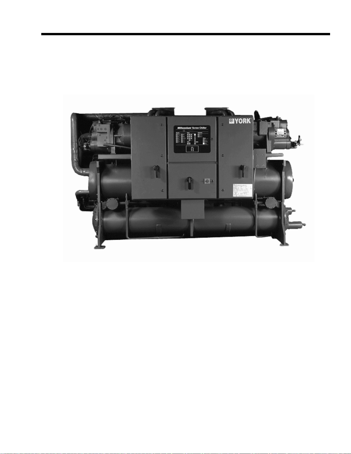
York YCWS W ater Cooled Screw Chillers
FORM 201.24-EG1
YORK YCWS Water-Cooled models provide chilled water for all air conditioning applications that
use central station air handling or terminal units. They are completely self-contained and are
designed for indoor (new or retrofit) installation. Each unit includes accessible semi-hermetic
screw compressors, a liquid cooler, water cooled condenser, and a user-friendly, diagnostic
Microcomputer Control Center all mounted on a rugged steel base. The units are produced at an
ISO 9001 registered facility. The YCWS chillers have certified ratings in accordance with ARI
Standard 550/590.
YORK INTERNATIONAL
3

Specifications
GENERAL
The Liquid Chiller will be completely assembled with all
interconnecting refrigerant piping and internal wiring,
ready for field installation.
• Each compressor will be mounted on isolator pads to
reduce transmission of vibration to the rest of the unit.
COOLER
The unit will be pressure-tested, evacuated, and charged
with Refrigerant-22, and York ‘L’ (POE) synthetic oil.
There will be an operational test, with water flowing
through the cooler, to check that each control device
operates correctly.
The unit will be covered with a coat of Caribbean Blue
enamel. Units are designed in accordance with NFPA
70 (National Electric Code), U.L. and cU.L. Standards,
ASHRAE/ANSI 15 Safety Code for Mechanical Refrigeration. All units are produced at an ISO 9001 registered facility. All YCWS chillers are rated and certified in
accordance with ARI Standard 550/590 at ARI conditions.
SEMI-HERMETIC YORK SCREW COMPRESSORS
• Continuous function, microprocessor controlled, 3- way
proportional Capacity Control Valve provides regulated
output pressure independent of valve input pressure
for a stable, smooth, and precise match of compressor capacity to cooling load to 10% of chiller capacity.
• Automatic spring return of capacity control valve to
minimum load position ensures compressor starting
at minimum motor load. Internal discharge check to
prevent rotor backspin upon shutdown.
• Acoustically tuned, internal discharge gas path elimi-
nates objectionable noise at the source, while optimizing flow for maximum performance.
• Reliable suction gas cooled, high efficiency, acces-
sible hermetic motor with APT2000 type magnet wire
and redundant overload protection using both thermistor and current overload protection.
• Suction gas screen and serviceable, 0.5 micron full
flow oil filter within the compressor housing.
The dual-circuit cooler will be the direct-expansion type,
with refrigerant in the tubes and chilled liquid flowing
through the baffled shell. The design working pressure
of the shell (liquid) side will be 150 PSIG (10.3 bar), and
300 PSIG (26.7 bar) for the tube (refrigerant) side.
The cooler will be constructed and tested in accordance
with the applicable sections of the ASME Pressure Vessel Code, Section VlII, Division (1). The water side will
be exempt per paragraph U-1, (c)(6).
The water baffles will be constructed of galvanized steel
to resist corrosion. The removable heads will allow access to the internally enhanced, seamless, copper tubes.
Vent and drain connections will be included.
The cooler will be covered with 3/4" (19.1 mm ) flexible,
closed-cell, foam insulation (K = 0.25).
CONDENSER
The condenser is a cleanable thru-tube type with steel
shell, copper tubes, removable water heads, and includes
integral subcooling. Refer to PHYSICAL DATA for design working pressures. The shell will be constructed
and tested in accordance with section Vll, division 1 of
the ASME pressure-vessel code. The water side is exempt per paragraph U-1 (c) of section VlII, division 1 of
the ASME pressure-vessel code. The condenser is
equipped with relief valves and will hold the full refrigerant charge for pumpdown.
REFRIGERANT CIRCUIT
Two independent refrigerant circuits will be furnished on
each unit. All piping will be copper with brazed joints.
The liquid line will include: a shutoff valve with charging
port; sightglass with moisture indicator; thermal expansion valve; solenoid valve; and high-absorption removable-core filter drier. The entire suction line and the liquid line between the expansion valve and the cooler will
be insulated with flexible, closed-cell, foam insulation.
• Cast iron compressor housing precisely machined for
optimal clearances and superb efficiency. Entire compressor, from suction to discharge has a Design Working Pressure of 450psig (31 bar).
• 350W compressor body cartridge heater.
4
POWER AND CONTROL PANELS
All controls and motor starting equipment necessary for
unit operation shall be factory wired and function tested.
The panel enclosures shall be designed to NEMA 1 (IP
32) and manufactured from powder-painted galvanized
steel.
YORK INTERNATIONAL

FORM 201.24-EG1
The Power and Control Panel shall be divided into a power
section for each electrical system, a common input section and a control section.
Each power panel shall contain:
Compressor starting contactors, control circuit
serving compressor capacity control, compressor
contactor coils and compressor motor overloads. The
compressor motor overloads contain current transformers which sense each phase, as an input to the
microprocessor, to protect the compressor motors
from damage due to: low input current, high input current, unbalanced current, single phasing, phase
reversal, and compressor locked rotor.
The common input section shall contain:
The control supply transformer providing 115V, customer relay board and control circuit switch disconnect/emergency stop device.
The control section shall contain:
On/Off rocker switch, microcomputer keypad and display, microprocessor board, I/O expansion board,
relay boards, and 24V fused power supply board.
MICROPROCESSOR CONTROLS
Fuzzy Logic control will be incorporated in the YCWS
range of chillers. Fuzzy Logic allows the control system
to monitor several key variables to provide tighter, more
stable chilled water temperature control. The control system monitors the leaving chilled water temperature to
track where it has been, where it is now, how fast it is
moving, and accurately adjusts the chiller operation in
anticipation of expected performance to minimize hunting and save energy.
The microprocessor shall have the following functions
and displays:
• A liquid crystal 40 character display with text provided
on two lines and light emitting diode backlighting for
outdoor viewing.
• A color-coded, 35 button, sealed keypad with sections for Display, Entry, Setpoints, Clock, Print, Program, and Unit On/Off Switch.
reset after power failure, automatic system optimization
to match operating conditions, software stored in nonvolatile memory (EPROM) to eliminate chiller failure due
to AC power failure.
The microprocessor can be directly connected to a YORK
ISN Building Automation System via the standard onboard RS485 communications port. This option also provides open system compatibility with other communications networks.
Programmed Setpoints shall be retained in a lithium battery backed RTC with a memory of five years.
Display - In Imperial (°F and PSIG) or SI (°C and BAR)
units, and for each circuit:
• Return and leaving chilled liquid
• Day, date and time. Daily start/stop times. Holiday
and Manual Override status.
• Compressor operating hours and starts. Automatic
or manual lead/lag. Lead compressor identification.
• Run permissive status. No cooling load condition.
Compressor run status.
• Anti-recycle timer and anti-coincident start timer status per compressor.
• Suction (and suction superheat), discharge, and oil
pressures and temperatures per System.
• Percent full load compressor motor current per phase
and average per phase. Compressor capacity control valve input steps.
• Cutout status and setpoints for: supply fluid temperature, low suction pressure, high discharge pressure
and temperature, high oil temperature, low and high
current, phase rotation safety, and low leaving liquid
temperature.
• Unloading limit setpoints for high discharge pressure
and compressor motor current.
• Liquid pull-down rate sensitivity (0.5°F to 5°F [0.3°C
to 3.0°C]/minute in 0.1°F [0.05°C] increments).
• Status of: evaporator heater, load and unload timers,
chilled water pump.
• Out of range message.
• Up to 6 fault shut down conditions.
• Standard Display Language is English, with an Option for Spanish.
The standard controls shall include: brine chilling or thermal storage, automatic pumpdown, run signal contacts,
demand load limit from external building automation system input, remote reset liquid temperature reset input,
unit alarm contacts, chilled liquid pump control, automatic
YORK INTERNATIONAL
Entry - Enter set point changes, cancel inputs, advance
day, change AM/PM.
Set Points - Chilled liquid temperature, chilled liquid
range, remote reset temperature range.
Clock - Time, daily or holiday start/stop schedule, manual
5

Specifications (Continued)
override for servicing.
Print - Operating data or system fault shutdown history
for last six faults. Printouts through an RS-232 port via a
separate printer (by others).
Program -
• Low leaving liquid temperature cutout, 300 to 600
second anti-recycle timer, lag compressor start time
delay, and average motor current unload point. Liquid temperature setpoint reset signal from YORK ISN
or building automation system (by others) via:
• Pulse width modulated (PWM) input for up to 40°F
(22°C) total reset as standard.
• Optional Building Automation System interface input
card for up to 20°F (11.1°C) reset using a: 4 to 20
mA, 0 to 10 Vdc input, or discrete reset input.
• NOTE: The Standard MicroPanel can be directly connected to a YORK ISN Building Automation System
via the standard onboard RS485 communication port.
This Option also provides open system compatibility
with other communications networks (BACnet™ &
LONMARK™ via interface through standard onboard
485 or 232 port and an external YorkTalk Translator.
• Additional functions (password protected) for programming by a qualified service technician:
Cutouts for low suction pressure, high discharge
pressure, high oil temperature.
Refrigerant type.
High discharge pressure unload setpoint.
Compressor motor current percent limit.
6
YORK INTERNATIONAL

Accessories & Options
FORM 201.24-EG1
ALTERNA TIVE REFRIGERANTS - Contact your nearest YORK of-
fice for information and availability on alternative HFC refrigerants.
ELECTRICAL OPTIONS:
MULTIPLE POINT POWER SUPPL Y CONNECTION -
Standard field power wiring connection on all models is Multiple
Point Power Connection to factory provided T erminal Blocks. T wo
field supplied electrical power circuits with appropriate branch circuit protection provide power to each of two motor control center
cabinets, located on either side of the Control panel on the front of
the chiller. Each cabinet contains starter elements for one compressor.
Optional to the Terminal Blocks for field power connection are
Non-Fused Disconnects or Circuit Breaker Switches with external,
lockable handles.
SINGLE POINT POWER CONNECTION - (Factory Mounted) An
optional configuration for field connection of a single electrical circuit to: either T erminal Block or Non-Fused Disconnect Switch with
lockable external handle (in compliance with Article 440 of N.E.C.,
to isolate unit power supply for service). Factory wiring is provided from the Terminal Block or Disconnect Switch to Factory
supplied individual system Circuit Breakers, Non-Fused Disconnect
switch with external, lockable handle or J Class Fuses/Fuse Block
in each of the two compressor motor control centers. (Note: Single
Point Non-Fused Disconnect Switch will not be supplied with individual system Non Fused Disconnect Switches with external, lockable handles in each of the two compressor motor control centers).
65 Ka HIGH VOL T AGE PROTECTION - Non-Fused Disconnect
Switch with fuses (200 & 575V) or Circuit Breakers (230, 380, &
460V) are used for applications where customers have a requirement for single point wiring with high “fault current” withstanding
capability. This option provides between 50Ka and 65Ka withstand
protection to the equipment.
BUILDING AUTOMATION SYSTEM INTERFACE (Factory
Mounted) – Provides means to reset the leaving chilled liquid
temperature or percent full load amps (current limiting) from the
BAS (Factory Mounted):
• Printed circuit board to accept 4 to 20 milliamp, 0 to 10 VDC,
or dry contact closure input from the BAS.
• A YORK ISN Building Automation System can provide a Pulse
Width Modulated (PWM) signal direct to the standard control
panel via the standard onboard RS485 port.
FLOW SWITCH – The flow switch or its equivalent must be furnished with each unit. 150 PSIG (10.5 bar) DWP – For standard
units. Johnson Controls model F61MG-1C Vapor-proof SPDT, NEMA
4X switch (150 PSIG [10.5 bar] DWP), -20°F to 250°F- (29°C to
121°C), with 1" NPT connection for upright mounting in horizontal
pipe. (Field mounted)
DIFFERENTIAL PRESSURE SWITCH - Alternative to the above mentioned Flow Switch. Pretemco Model DPS 300A-P4OPF-82582-S
(20.7bar max working pressure). SPDT 5 amp 125/250 V AC switch.
Range: 0 - 2.8bar, deadband: 0.003 - 0.005bar , with 1/4 NPTE pressure connections.
LANGUAGE LCD AND KEYP AD - Standard display language and
keypad is in English. Spanish is available as an option.
PRINTER KIT - Printer for obtaining printout of unit operating and
history data. (Field Mounted)
MULTIPLE UNIT SEQUENCE CONTROL (Field Mounted) - Sequencing Control with automatic unit sequencing. Necessary items
for operation and control of up to eight units with parallel water
circuits. Includes software and mixed liquid temperature sensor
(interconnecting wiring by others).
PRESSURE VESSEL CODES - Coolers and condensers can be
supplied in conformance with the following pressure codes:
A.S.M.E. (Standard)
CHICAGO CODE RELIEF V ALVES (Factory Mounted) - Unit will be
provided with relief valves to meet Chicago Code requirements.
ACCESSORIES:
FLANGES (Weld T ype) – Consists of 150 PSI (10.5 bar ) standard
cooler (150 lb) R.F . flanges to convert to flanged cooler-connections and includes companion flanges. (Field mounted)
FLANGES (Victaulic T ype) – Consists of (2) Flange adapter for
grooved end pipe (standard 150 PSI [10.5 bar] cooler). Includes
companion flanges. (Field mounted)
VIBRATION ISOLA TION:
• Neoprene Isolators – Recommended for normal installations.
Provides very good performance in most applications for the
least cost. (Field mounted)
• 1" Spring Isolators – Level adjustable, spring and cage type
isolators for mounting under the unit base rails. 1" nominal deflection may vary slightly by application. (Field mounted)
• 2" Seismic Spring Isolators – Restrained Spring-Flex Mountings
incorporate a rugged welded steel housing with vertical and
horizontal limit stops. Housings designed to withstand a minimum 1.0g accelerated force in all directions to 2". Level adjustable, deflection may vary slightly by application. (Field-mounted)
ALTERNA TIVE CHILLED FLUID APPLICA TIONS:
Standard water chilling application range is 40°F to 50°F (4.4°C to
10°C) Leaving Chilled Water T emperature. To protect against nuisance safety trips below 40°F (4.4°C) and reduce the possibility of
cooler damage due to freezing during chiller operation, the unit
microprocessor automatically unloads the compressors at abnormally low suction temperature (pressure) conditions , prior to safety
shutdown.
• Process Brine Option – Process or other applications requir-
ing chilled fluid below 40°F (4.4°C) risk water freezing in the
evaporator, typically overcome by using antifreeze. For these
applications, the chiller system incorporates brine (ethylene or
propylene glycol solution), and the system design Leaving Chilled
Fluid T emperature must be provided on the order form to ensure
proper factory configuration.
• Thermal Storage Option – Thermal Storage equires special
capabilities from a chiller, including the ability to ‘charge’ an ice
storage tank, then possibly automatically reset for operation at
elevated Leaving Chilled Fluid T emperatures as required by automatic building controls. The Thermal Storage Option provides
Ice Storage duty Leaving Chilled Fluid setpoints from 25°F to
15°F( -4°C to -10°C) minimum during charge cycle, with a Reset
range of 36°F (20°C) supply fluid temperature.
YORK INTERNATIONAL
7
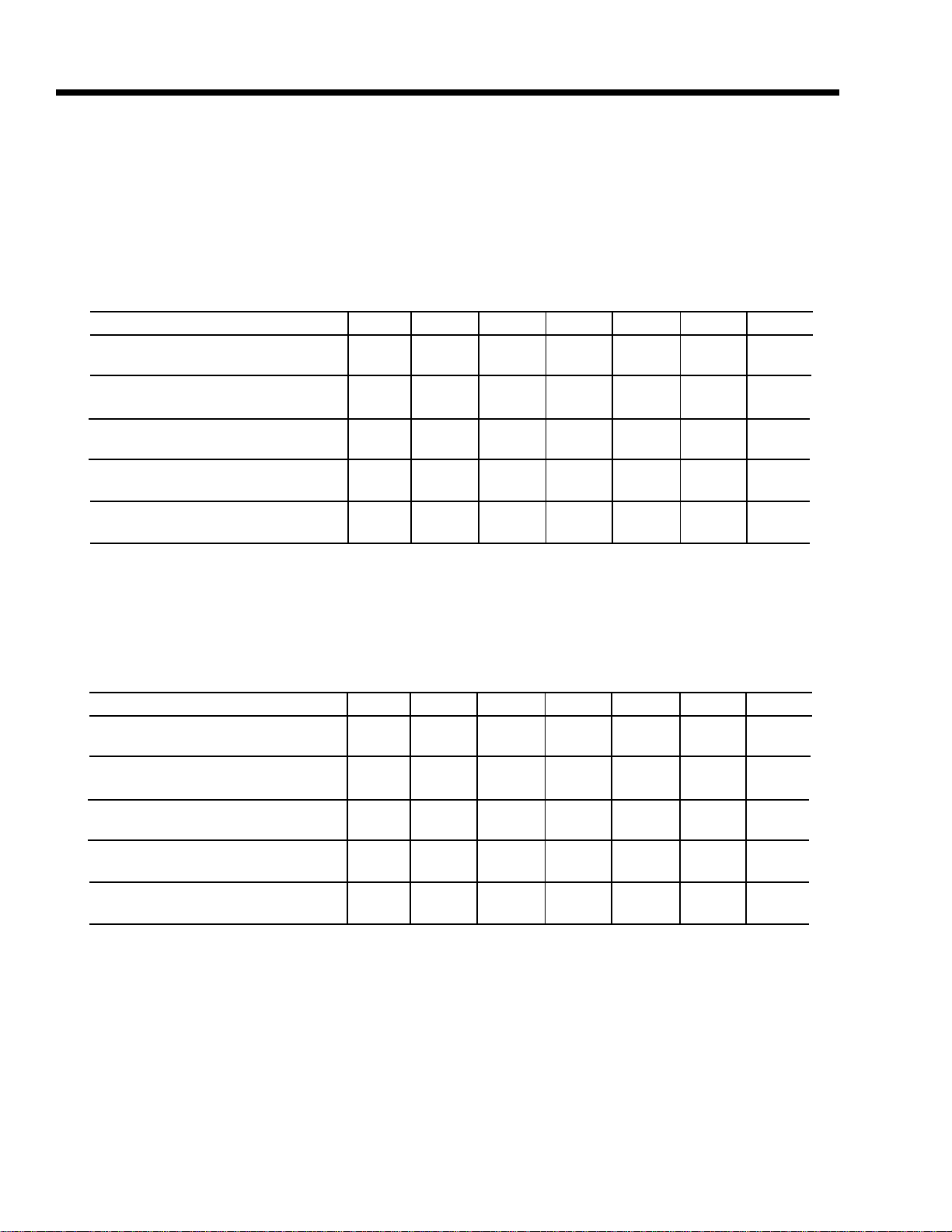
Design Parameters
English
YCWS 0100SC 0120SC 0140SC 0180SC 0200SC 0220SC 0240SC
Min. Cooler Water Flow - GPM 200 200 200 260 260 300 300
Max. Cooler Water Flow - GPM 506 506 506 695 695 830 830
Min. Cond. Water Flow - GPM 193 193 193 330 330 330 330
Max. Cond. Water Flow - GPM 645 645 64 5 1050 1050 1050 1050
Min. Lvg. Liquid Temp. - °F 40 40 40 40 40 40 40
Max. Lvg. Liquid Temp. - °F 50 50 50 50 50 50 50
Min. Ent. Cond. Water Temp - °F 75 75 75 75 75 75 75
Max. Ent. Cond. Water Temp - °F 95 95 95 95 95 95 95
Min. Equipment Room Temp. - °F 40 40 40 40 40 40 40
Max. Equipment Room Temp. - °F 115 115 115 115 115 115 115
SI
YCWS 0100SC 0120SC 0140SC 0180SC 0200SC 0220SC 0240SC
Min. Cooler Water Flow - l/sec 12.6 12.6 12.6 16.4 16.4 18.9 18.9
Max. Cooler Water Flow - l/sec 31.9 31.9 31.9 43.8 43.8 52.4 52.4
Min. Cond. Water Flow - l/sec 12.2 12.2 12.2 20.8 20.8 20.8 20.8
Max. Cond. Water Flow - l/sec 40.7 40.7 40.7 66.2 66.2 66.2 66.2
Min. Lvg. Liquid Temp. - °C 4.4 4.4 4.4 4.4 4.4 4.4 4.4
Max. Lvg. Liquid Temp. - °C 10.0 10.0 10.0 10.0 10.0 10.0 10.0
Min. Ent. Cond. Water Temp - °C 23.8 23.8 23.8 23.8 23.8 23.8 23.8
Max. Ent. Cond. Water Temp - °C 35..0 35..0 35..0 35..0 35..0 35..0 35..0
Min. Equipment Room Temp. - °C 4.4 4.4 4.4 4.4 4.4 4.4 4.4
Max. Equipment Room Temp. - °C 46.1 46.1 46.1 46.1 46.1 46.1 46.1
8
YORK INTERNATIONAL
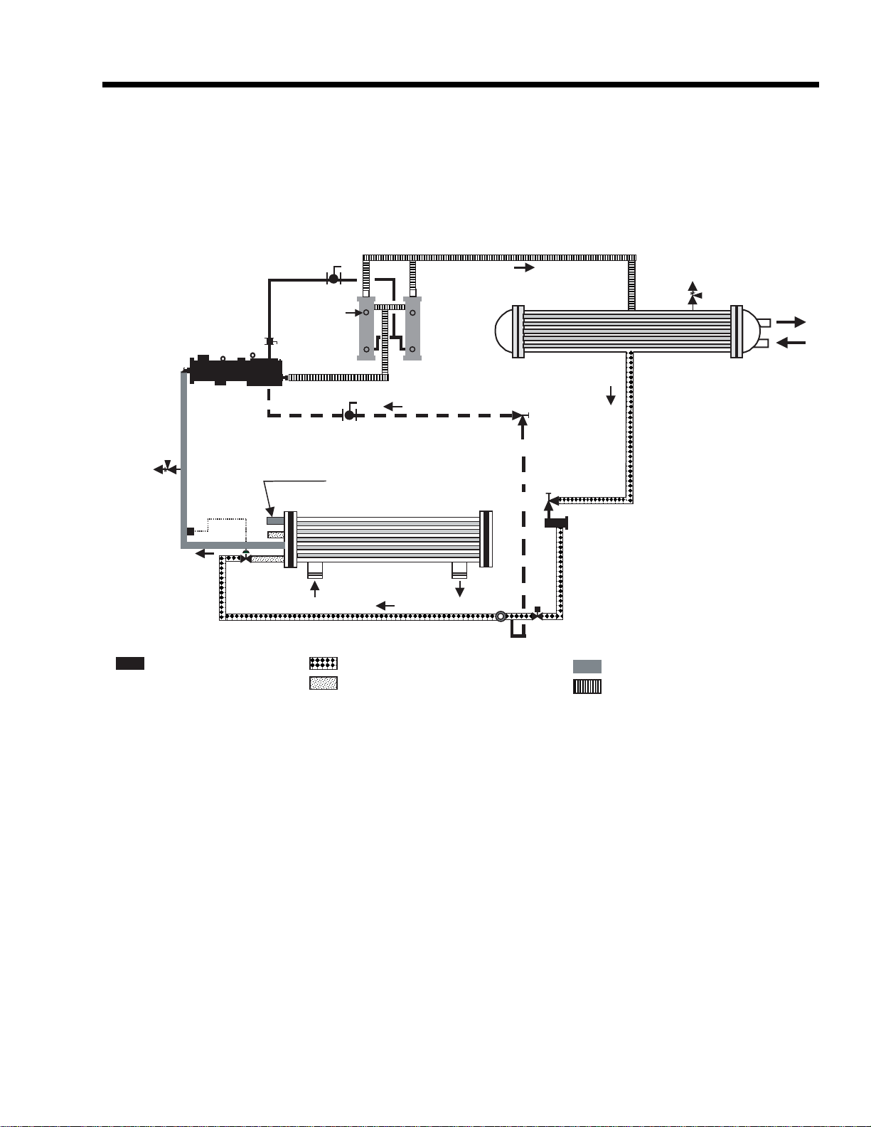
Relief
Valve
FORM 201.24-EG1
Relief
Val ve
Oil
SV = Solenoid Valve
Compressor
TEV
SG = Sight Glass
SG
Refrigerant Circuit No 2
Cooler
High Pressure Subcooled Liquid
Low Pressure Liquid
TEV = Thermostatic Expansion Valve
Oil
Separators
Oil Cooling
Liquid Injection
Condenser
SG
SV
Low Pressure Superheated Vapour
High Pressure Superheated Vapour
Low-pressure liquid refrigerant enters the cooler tubes and is evaporated and superheated by the heat energy absorbed
from the chilled liquid passing through the cooler shell. Low-pressure vapor enters the compressor where pressure and
superheat are increased. High-pressure vapor is passed through the oil separator where heat is rejected to the condenser water passing through the tubes. The fully condensed and subcooled liquid leaves the condenser and enters the
expansion valve, where pressure reduction and further cooling take place. The low pressure liquid refrigerant then
returns to the cooler. Each refrigerant circuit utilizes liquid injection, maintaining efficient oil temperature operation
within the compressor.
YORK INTERNATIONAL
9
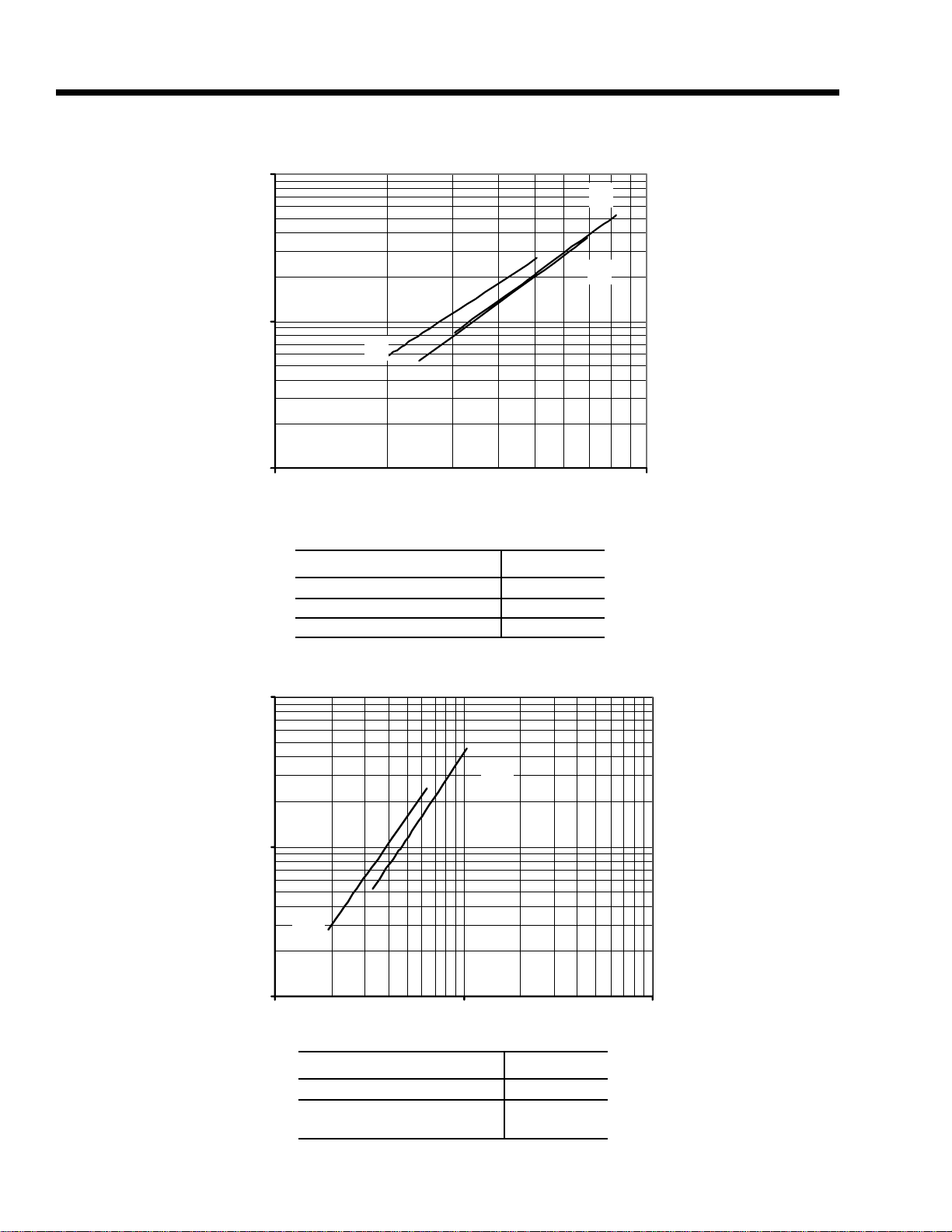
Pressure Drops
FIGURE 1 - COOLER WA TER PRESSURE DROP CURVES (ENGLISH)
100
O)
2
10
Pressure Drop (H
1
100 1000
Q
P
O
Flow (GPM)
YCWS Model Number Cooler
0100SC, 0120SC, 0140SC
0180SC, 0200SC
0220SC, 0240SC
O
P
Q
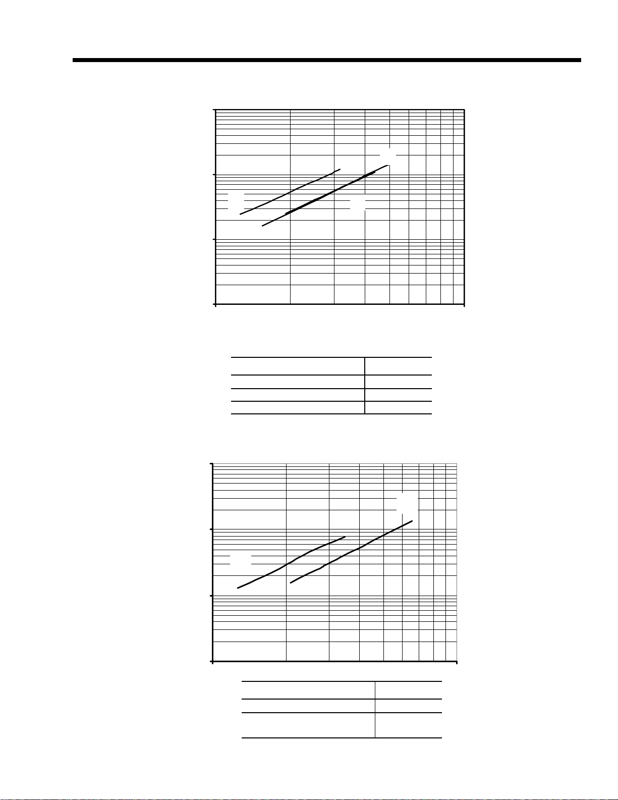
FIGURE 3 - CONDENSER WA TER PRESSURE DROP CURVES (ENGLISH)
100
O)
2
10
U
Pressure Drop (H
S
10
1
100 1000 10000
Flow (GPM)
YCWS Model Number Cooler
0100SC, 0120SC, 0140SC
S
0180SC, 0200SC
0220SC, 0240SC
U
YORK INTERNATIONAL
100
FIGURE 2 - COOLER WA TER PRESSURE DROP CURVES (SI)
1000
Q
100
FORM 201.24-EG1
O
10
P
Pressure Drop (kPa)
1
10
Flow (l/s)
YCWS Model Number Cooler
0100SC, 0120SC, 0140SC
0180SC, 0200SC
0220SC, 0240SC
O
P
Q
FIGURE 4 - CONDENSER WA TER PRESSURE DROP CURVES (SI)
1000
YORK INTERNATIONAL
100
S
Pressure Drop (kPa)
10
1
10 100
0100SC, 0120SC, 0140SC
Flow (l/s)
0180SC, 0200SC
0220SC, 0240SC
U
S
U
11
Selection Data
GUIDE TO SELECTION
Complete water chilling capacity ratings for YORK YCWS
chillers are shown on the following pages to cover the
majority of job requirements. For any application beyond the scope of this Engineering Guide, consult your
nearest YORK Office.
SELECTION RULES
1. RATINGS - YCWS 200, 230 380, 460 & 575-3-60 rating are certified in accordance with ARI standard 550/
590, at the ARI standard condition. Rating not at standard ARI conditions are rated in accordance with ARI
rating procedures. These ratings may be interpolated
but should not be extrapolated.
2. COOLING WATER QUANTITY - Ratings are based
on 10ºF chilled water range. Use the chilled water
correction factors (below) for other ranges except as
limited by water pressure drop, minimum or maximum
water flows for the cooler.
3. CONDENSER WATER QUANTITY – Rating are applicable from 2 to 4 gpm/ton as limited by water pressure drop or minimum or maximum water flows for
the condenser. Using the tabulated MBH, the Cond.
GPM is calculated as follows:
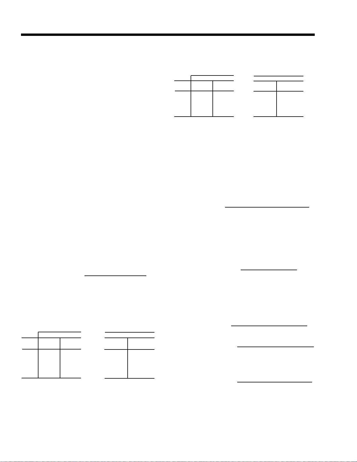
COND FOULING FACTORS
T emp
Split
8 0.9998 1.0004 0.9957 1.0072
10 1.0000 1.0000 0.9959 1.0068
12 1.0001 0.9998 0.9961 1.0065
14 1.0001 0.9998 0.9965 1.0060
Note: Temperature split factors @ 95ºF Leaving Condenser Water
Temp (LCWT).
0.00025 x 0.0005
Tons
Compr
kW
Tons
Compr
kW
METHOD OF SELECTION
If the duty requires a 10ºF range on both the cooler and
condenser, see “Ratings”. For water ranges other than
10ºF, use the following procedure.
1. Determine capacity required from the following formula
Capacity (tons) =
GPM x Chilled Water Range (ºF)
24
2. After applying any fouling factor corrections, the actual condenser heat rejection may be determined as
follows:
Heat Rejection (Btuh) = (Tons x 12,000) + (kW x 3415)
Cond. GPM =
Cond. Water Range (ºF)
MBH x 2
4. FOULING FACTORS – Rating are based on 0.0001
evaporator and 0.00025 condenser fouling factor. For
other fouling factors, consult the table below or contact your YORK representative.
EVAP FOULING FACTORS
0.0001 x 0.00025
T emp
Split
10 1.0000 1.0000 0.9982 1.0001
12 1.0133 0.9993 0.9978 1.0001
14 1.0248 0.9986 0.9979 1.0001
Note: Temperature split factors @ 44ºF Leaving Chilled Liquid Temp
(LCLT)
Tons
6 0.9692 1.0015 0.9972 1.0001
8 0.9849 1.0008 0.9980 1.0001
Compr
kW
Tons
Compr
kW
Heat Rejection (MBH) =
Heat Rejection (Btuh)
1000
= (Tons x 12) = (kW x 3.415)
3. Determine condensing water requirements for water
cooled models as follows:
Condenser Tons =
Cond. Water GPM =
Heat Rejection (MBH) x 1000
15,000
Condenser Tons x 30
Condenser Water Range (ºF)
Or combine the two formulas:
Cond. Water GPM =
Condenser Water Range (ºF)
MBH x 2
12
YORK INTERNATIONAL

FORM 201.24-EG1
SAMPLE SELECTION
Water Cooled Condenser (YCWS)
GIVEN – Chill 200 GPM of water from 56ºF to 44ºF and
0.0001 evaporator fouling factor with 85ºF to 95ºF condensing water available. Fouling factor of 0.0005 special field for the condenser.
FIND – The required unit size capacity, kW, EER, and
water pressure drop.
SOLUTION:
1. Chilled water range = 56ºF - 44ºF = 12ºF and correction factors are 1.0133 for Tons and 0.9993 for kW for
the cooler.
2. Capacity (tons) =
= 200 x 12
24
GPM x Chilled Water Range
24
= 100TR
2. From the rating, a model YCWS0120SC has a capacity range required. For the cooler leaving water
temperature of 44ºF and a condenser leaving water
temperature of 95ºF, the unit capacity rating table indicates:
EER =
Tons x 12 = 95.0 X 12 = 15.4
Kw 74
4. Determine the cond. Heat rejection as follows:
Heat Rejection (MBH) = (Tons x 12) + (kW x 3.415)
= (95.0 x 12) + (74 x 3.415)
= 1140 + 253
= 1393
5. Determine GPM condensing water as follows:
GPM Condenser Water =
Cond Water Range
MBH x2
6. From curves on pages 10 and 11, the pressure drops
with 200GPM through the cooler and 288 through the
condenser of the Model YCWS120SC
Cooler Pressure Drop at 200 GPM = 2.9ft
Condenser Pressure Drop at 288 GPM = 5.5ft
Tons = 110.3
KW = 86.2
EER = 15.4
Correcting for the 12ºF chilled water range and the 0.0005
condenser-fouling factor:
Tons = 110.3 x 1.0133 x 0.9961 = 111.3TR
KW = 86.2 x 0.9993 x 1.0065 = 86.7
The unit is suitable.
3. Determine the average full load kW and EER at 95.0
Tons
95.0
X (86.7) = 74KW
111.3
YORK INTERNATIONAL
13
Ratings (R-22 English)
LEA VING CONDENSER WA TER TEMPERA TURE (°F)
LCWT 85.0 95.0 105.0
(°F) TONS KW MBH EER TONS KW MBH EER TONS K W MBH EER
YCWS0100SC
40.0 89.4 63.3 1288.0 17.0 84.1 71.5 1253.0 14.1 78.7 80.7 1219.0 11.7
42.0 93.1 63.4 1333.0 17.6 87.7 71.8 1297.0 14.7 82.1 80.9 1260.0 12.2
44.0 96.9 63.5 1379.0 18.3 91.3 72.0 1341.0 15.2 85.6 81.1 1304.0 12.7
45.0 98.8 63.6 1402.0 18.7 93.2 72.2 1364.0 15.5 87.4 81.2 1325.0 12.9
46.0 100.7 63.6 1426.0 19.0 95.0 72.3 1387.0 15.8 89.2 81.4 1348.0 13.2
48.0 104.7 63.5 1473.0 19.8 98.9 72.5 1434.0 16.4 92.9 81.7 1393.0 13.7
50.0 108.8 63.4 1522.0 20.6 102.8 72.7 1482.0 17.0 96.7 81.9 1439.0 14.2
YCWS0120SC
40.0 108.0 75.6 1553.0 17.1 101.7 85.6 1512.0 14.3 95.3 96.6 1473.0 11.8
42.0 1 12.3 75.8 1607.0 17.8 105.9 85.9 1564.0 14.8 99.3 96.9 1522.0 12.3
44.0 1 16.8 76.0 1661.0 18.5 110.3 86.2 1617.0 15.4 103.5 97.2 1573.0 12.8
45.0 1 19.1 76.0 1689.0 18.8 112.5 86.3 1644.0 15.6 105.6 97.3 1599.0 13.0
46.0 121.5 76.0 1717.0 19.2 114.7 86.5 1671.0 15.9 107.8 97.5 1626.0 13.3
48.0 126.2 76.0 1774.0 19.9 119.3 86.7 1727.0 16.5 112.2 97.8 1680.0 13.8
50.0 131.1 75.9 1832.0 20.7 124.0 86.9 1784.0 17.1 116.7 98.1 1735.0 14.3
YCWS0140SC
40.0 127.8 88.1 1834.0 17.4 120.4 99.8 1786.0 14.5 112.9 112.9 1740.0 12.0
42.0 132.9 88.3 1896.0 18.1 125.4 100.2 1847.0 15.0 1 17.7 1 13.1 1798.0 12.5
44.0 138.2 88.5 1960.0 18.7 130.5 100.5 1909.0 15.6 122.6 113.4 1858.0 13.0
45.0 140.9 88.5 1993.0 19.1 133.1 100.7 1940.0 15.9 125.1 113.6 1889.0 13.2
46.0 143.6 88.6 2025.0 19.5 135.7 100.8 1973.0 16.2 127.7 113.7 1920.0 13.5
48.0 149.2 88.6 2093.0 20.2 141.1 101.1 2038.0 16.7 132.8 114.1 1983.0 14.0
50.0 154.9 88.6 2161.0 21.0 146.6 101.3 2105.0 17.4 138.1 114.4 2047.0 14.5
IPLV = 18.8
IPLV = 18.2
IPLV = 19.3
YCWS0180SC
40.0 156.6 97.9 2213.0 19.2 147.7 1 11.5 2153.0 15.9 138.5 126.2 2093.0 13.2
42.0 163.2 98.0 2292.0 20.0 153.9 1 11.8 2229.0 16.5 144.5 126.5 2166.0 13.7
44.0 169.6 97.9 2369.0 20.8 160.3 112.0 2306.0 17.2 150.6 126.8 2240.0 14.3
45.0 172.9 97.9 2409.0 21.2 163.6 112.1 2345.0 17.5 153.7 126.9 2278.0 14.5
46.0 176.5 97.8 2452.0 21.7 166.5 112.2 2380.0 17.8 156.9 127.1 2317.0 14.8
48.0 183.5 97.5 2535.0 22.6 173.6 112.4 2466.0 18.5 163.4 127.4 2395.0 15.4
50.0 190.9 97.2 2622.0 23.6 180.5 112.5 2549.0 19.3 170.0 127.7 2476.0 16.0
NOTES:
1. Tons = Unit Cooling Capacity Output
2. kW = Compressor Input Power
3. MBH = Condenser heat rejection
4. EER = Chiller Energy Efficiency Ratio (Capacity [Tons x 12] ÷ kW)
5. LCWT = Leaving Chilled Water Temperature
6. Ratings based on 2.4 GPM cooler water per ton
7. Ratings certified in accordance with ARI Standard 550/590-98 up to 200 tons.
14
IPLV = 20.9
YORK INTERNATIONAL
FORM 201.24-EG1
LEA VING CONDENSER WA TER TEMPERA TURE (°F)
LCWT 85.0 95.0 105.0
(°F) TONS KW MBH EER TONS KW MBH EER TONS KW MBH EER
YCWS0200SC
IPLV = 21.8
40.0 179.1 110.1 2525.0 19.5 168.8 125.4 2454.0 16.2 158.3 142.0 2384.0 13.4
42.0 186.3 110.2 2611.0 20.3 175.7 125.7 2538.0 16.8 165.1 142.3 2467.0 13.9
44.0 194.0 110.1 2703.0 21.1 183.2 126.0 2629.0 17.4 171.9 142.6 2549.0 14.5
45.0 197.8 110.1 2749.0 21.6 186.7 126.1 2671.0 17.8 175.6 142.8 2594.0 14.8
46.0 201.7 110.0 2796.0 22.0 190.6 126.2 2717.0 18.1 179.1 143.0 2637.0 15.0
48.0 209.6 109.8 2890.0 22.9 198.3 126.4 2811.0 18.8 186.6 143.3 2729.0 15.6
50.0 217.7 109.4 2986.0 23.9 206.2 126.5 2906.0 19.6 194.3 143.7 2821.0 16.2
YCWS0220SC
IPLV = 20.8
40.0 195.2 121.3 2756.0 19.3 183.8 138.1 2677.0 16.0 172.5 156.2 2603.0 13.3
42.0 203.1 121.4 2851.0 20.1 191.7 138.5 2773.0 16.6 179.7 156.6 2691.0 13.8
44.0 211.2 121.4 2948.0 20.9 199.6 138.8 2869.0 17.3 187.5 157.0 2786.0 14.3
45.0 215.3 121.4 2997.0 21.3 203.7 138.9 2918.0 17.6 191.2 157.2 2831.0 14.6
46.0 219.5 121.3 3047.0 21.7 207.6 139.1 2966.0 17.9 195.4 157.4 2882.0 14.9
48.0 228.4 121.1 3154.0 22.6 215.4 139.3 3060.0 18.6 203.4 157.8 2980.0 15.5
50.0 237.3 120.7 3260.0 23.6 224.7 139.4 3171.0 19.3 21 1.5 158.2 3078.0 16.0
YCWS0240SC
IPLV = 21.2
40.0 210.6 132.7 2981.0 19.0 198.0 151.0 2891.0 15.7 185.9 170.7 2814.0 13.1
42.0 219.2 132.9 3084.0 19.8 205.9 151.4 2988.0 16.3 193.9 171.2 2911.0 13.6
44.0 228.1 133.0 3191.0 20.6 215.4 151.8 3102.0 17.0 202.3 171.6 3014.0 14.1
45.0 232.6 132.9 3245.0 21.0 219.7 152.0 3155.0 17.3 206.5 171.9 3065.0 14.4
46.0 237.2 132.9 3299.0 21.4 224.1 152.2 3208.0 17.7 210.8 172.1 31 16.0 14.7
48.0 246.5 132.7 3411.0 22.3 233.1 152.4 3317.0 18.4 219.4 172.6 3222.0 15.3
50.0 256.1 132.4 3524.0 23.2 242.3 152.6 3429.0 19.1 228.3 173.1 3330.0 15.8
NOTES:
1. Tons = Unit Cooling Capacity Output
2. kW = Compressor Input Power
3. MBH = Condenser heat rejection
4. EER = Chiller Energy Efficiency Ratio (Capacity [Tons x 12] ÷ kW)
5. LCWT = Leaving Chilled Water Temperature
6. Ratings based on 2.4 GPM cooler water per ton
7. Ratings certified in accordance with ARI Standard 550/590-98 up to 200 tons.
YORK INTERNATIONAL
15
Ratings (R-22 SI)
LEAVING CONDENSER W A TER TEMPERA TURE (°C)
LCWT 30.0 35.0 40.0
(°C) KWo KWi KW COP KWo KWi KW COP KWo KWi KW COP
YCWS0100SC
5.0 316.4 64.1 380.0 4.9 299.5 71.6 371.0 4.2 282.3 79.8 362.0 3.5
6.0 328.1 64.3 392.0 5.1 310.8 71.8 382.0 4.3 293.2 80.0 373.0 3.7
7.0 340.1 64.4 404.0 5.3 322.4 72.1 394.0 4.5 304.3 80.2 384.0 3.8
8.0 352.4 64.5 416.0 5.5 334.4 72.3 406.0 4.6 315.7 80.4 396.0 3.9
9.0 365.1 64.5 429.0 5.7 346.5 72.5 419.0 4.8 327.6 80.7 408.0 4.1
10.0 377.9 64.4 442.0 5.9 359.0 72.7 431.0 4.9 339.5 81.0 420.0 4.2
YCWS0120SC
5.0 382.2 76.7 458.0 5.0 362.1 85.7 447.0 4.2 341.6 95.6 437.0 3.6
6.0 396.1 76.9 473.0 5.2 375.6 86.0 461.0 4.4 354.6 95.8 450.0 3.7
7.0 410.5 77.0 487.0 5.3 389.5 86.3 475.0 4.5 368.0 96.1 464.0 3.8
8.0 425.1 77.1 502.0 5.5 403.6 86.5 490.0 4.7 381.7 96.4 478.0 4.0
9.0 440.1 77.1 517.0 5.7 418.2 86.7 504.0 4.8 395.7 96.7 492.0 4.1
10.0 455.5 77.1 532.0 5.9 432.9 86.9 519.0 5.0 410.0 96.9 507.0 4.2
YCWS0140SC
5.0 452.5 89.3 541.0 5.1 428.9 100.0 528.0 4.3 405.4 111.6 517.0 3.6
6.0 468.9 89.5 558.0 5.2 444.9 100.3 545.0 4.4 420.5 111.8 532.0 3.8
7.0 485.7 89.7 575.0 5.4 461.2 100.6 561.0 4.6 436.0 112.1 548.0 3.9
8.0 502.9 89.8 592.0 5.6 477.8 100.8 578.0 4.7 452.3 112.4 564.0 4.0
9.0 520.5 89.9 610.0 5.8 494.9 101.1 596.0 4.9 468.6 112.8 581.0 4.2
10.0 538.6 89.9 628.0 6.0 511.9 101.3 613.0 5.1 485.6 113.1 598.0 4.3
YCWS0180SC
5.0 554.1 99.4 653.0 5.6 525.2 111.7 636.0 4.7 496.0 124.8 620.0 4.0
6.0 574.6 99.4 674.0 5.8 545.2 111.9 657.0 4.9 515.0 125.1 640.0 4.1
7.0 594.4 99.4 693.0 6.0 565.5 112.1 677.0 5.0 534.1 125.4 659.0 4.3
8.0 616.7 99.3 716.0 6.2 586.3 112.3 698.0 5.2 554.7 125.7 680.0 4.4
9.0 638.9 99.2 738.0 6.4 608.8 112.5 721.0 5.4 575.7 125.9 701.0 4.6
10.0 661.6 98.9 760.0 6.7 629.2 112.5 741.0 5.6 596.4 126.2 722.0 4.7
NOTES:
1. KWo = Unit kW Cooling Capacity Output
2. KWi = Compressor kW Input
3. COP = Coefficient of Performance
4. LCWT= Leaving Chilled Water Temperature
5. Ratings based on 0.047 l/s cooler water per kW.
16
YORK INTERNATIONAL
Loading...