


INSTALLATION |
|
MANUAL |
|
CONTENTS |
|
INTRODUCTION ............................................................. |
2 |
HEAT LOSS .................................................................... |
2 |
LOCATION OF UNIT ...................................................... |
2 |
AIR CONDITIONING....................................................... |
4 |
COMBUSTION AIR......................................................... |
4 |
CHIMNEY VENTING ....................................................... |
4 |
OIL TANK........................................................................ |
6 |
PIPING INSTALLATION ................................................. |
6 |
ELECTRICAL CONNECTIONS ...................................... |
6 |
CIRCULATING AIR BLOWER........................................ |
7 |
OIL BURNER .................................................................. |
8 |
FURNACE INSTALLATION SET-UP............................. |
9 |
MAINTENANCE AND SERVICE................................... |
10 |
OPERATING INSTRUCTIONS ..................................... |
10 |
TABLE A-1: BECKETT OIL BURNER SET-UP ........... |
11 |
TABLE A-2: DIRECT DRIVE BLOWER SET-UP ......... |
12 |
TABLE A-3: BELT DRIVE BLOWER SET-UP ............. |
12 |
TABLE A-4: DIRECT DRIVE BLOWER |
|
CHARACTERISTICS .................................................... |
13 |
TABLE A-5: BELT DRIVE BLOWER |
|
CHARACTERISTICS .................................................... |
13 |
GENERAL DIMENSIONS - P2LBX16F14501............... |
14 |
GENERAL DIMENSIONS - P4LBX20F19001............... |
14 |
GENERAL DIMENSIONS - P4LBX20F19001............... |
15 |
GENERAL DIMENSIONS - P3DHX12F08001 .............. |
15 |
GENERAL DIMENSIONS - P3DHX12F08001 .............. |
16 |
GENERAL DIMENSIONS - P2DHX16F12001 .............. |
16 |
GENERAL DIMENSIONS - P2DHX16F12001 .............. |
17 |
WIRING DIAGRAM: MODEL P3DHX12F08001........... |
18 |
WIRING DIAGRAM: MODEL P2DHX16F12001........... |
18 |
WIRING DIAGRAM: MODEL P2LBX16F14501 ........... |
19 |
WIRING DIAGRAM: MODEL P4LBX20F19001 ........... |
19 |
R7184 DETAILED SEQUENCE OF OPERATION........ |
20 |
R7184 LED DIAGNOSTIC LIGHT................................. |
22 |
Table C-1: Cad Cell Resistance................................. |
22 |
R8184N NOTES............................................................ |
22 |
TABLE C-2: R7184 TROUBLESHOOTING................. |
23 |
TABLE C-3: SYSTEM AND GENERAL |
|
TROUBLESHOOTING .................................................. |
25 |
P4LBX20F19001 ASSEMBLY NOTES......................... |
28 |
P3DHX SERIES DOWNFLOW CONFIGURATION |
|
NOTES .......................................................................... |
28 |
P3DHX12F08001 VESTIBULE KIT............................... |
29 |
REPAIR PART LIST – P3DHX12F08001A................... |
30 |
REPAIR PART LIST – P2DHX16F12001A................... |
31 |
REPAIR PART LIST – P2LBX16F14501A ................... |
32 |
REPAIR PART LIST – P4LB SERIES .......................... |
33 |
REPLACEMENT PART CONTACT INFORMATION.... |
34 |
OIL-FIRED WARM AIR
FURNACE
P3DHX12F08001 P2DHX16F12001 (Downflow or Horizontal Models)
P2LBX16F14501 P4LBX20F19001
(Lowboy Models)
Read this manual completely before beginning installation.
Important: These instructions must be kept with the furnace for future reference.
1

IMPROPER INSTALLATION MAY CREATE A CONDITION WHERE THE OPERATION OF THE PRODUCT COULD CAUSE PERSONAL INJURY OR PROPERTY DAMAGE.
IMPROPER INSTALLATION, ADJUSTMENT, ALTERATION, SERVICE OR MAINTENANCE CAN CAUSE INJURY OR PROPERTY DAMAGE. REFER TO THIS MANUAL FOR ASSISTANCE OR ADDITIONAL INFORMATION, CONSULT A QUALIFIED INSTALLER, SERVICE AGENCY OR THE FUEL SUPPLIER.
THIS PRODUCT MUST BE INSTALLED IN STRICT COMPLIANCE WITH THESE INSTALLATION INSTRUCTIONS AND ANY APPLICABLE LOCAL, STATE, AND NATIONAL CODES INCLUDING BUT NOT LIMITED TO: BUILDING, ELECTRICAL AND MECHANICAL CODES.
The furnace area must not be used as a broom closet or for any other storage purposes, as a fire hazard may be created. Never store items such as the following on, near or in contact with the furnace:
1.Spray or aerosol cans, rags, brooms, dust mops, vacuum cleaners or other cleaning tools.
2.Soap powders, bleaches, waxes or other cleaning compounds; plastic items or containers, gasoline, kerosene, cigarette lighter fluid, dry cleaning fluids, or other volatile fluids.
3.Paint thinners or other painting materials and compounds.
4.Paper bags, boxes, or other paper or cardboard products.
Never operate the furnace with the blower door removed. To do so could result in serious personal injury and/or equipment damage.
DO NOT USE GASOLINE, CRANKCASE OIL, OR ANY OTHER OIL CONTAINING GASOLINE AS A FUEL FOR THIS FURNACE.
INTRODUCTION
Please read these instructions completely and carefully before installing and operating the furnace.
The furnace must be installed and set up by a qualified contractor.
Model P3DHX12F08001 is an oil fired forced air multi-positional furnace, with an output capacity range of 60,000 BTU/Hr. to 90,000 BTU/Hr. Model P2DHX16F12001 is an oil fired forced air multi-positional furnace, with an output capacity range of 91,000 BTU/Hr. to 128,000 BTU/Hr. These models may be installed in the down-flow position, as well as both horizontal positions.
Model P2LBX16F14501 is a rear-breech lowboy model with an output range of 130,000 to 143,000 BTUH. Model P4LBX20F19001 is a rear-breech lowboy model with an output range of 168,000 to 188,000 BTUH.
All models are listed with the Canadian Standards Association, (CSA), and comply with the standards of both the United States and Canada for use with No. 1 (Stove) and No. 2 (Furnace) Oil.
In the United States, the installation of the furnace and related equipment shall be installed in accordance with the regulations of NFPA No. 31, Installation of Oil Burning Equipment, as well as in accordance with local codes.
In Canada, the installation of the furnace and related equipment shall be installed in accordance with the regulations of CAN/CSA - B139, Installation Code For Oil Burning Equipment, as well as in accordance with local codes.
When installation or application questions arise, regulations prescribed in the National Codes and Local Regulations take precedence over the general instructions provided with this installation manual. When in doubt, please consult your local authorities.
All P*DHX models are shipped assembled, pre-wired, ready for down-flow operation. P*DHX furnace models are air conditioning ready. The furnace should be carefully inspected for damage when being unpacked.
The P2LBX16F14501 model is shipped assembled, pre-wired, and ready for lowboy furnace applications. The P2LBX16F14501 model is air conditioning ready.
The P4LBX20F19001 is shipped in two pieces, a furnace section and a blower section, and must be assembled at the installation site. Some field wiring is required. The P4LBX20F19001 is shipped as a heating only furnace; however, air conditioning may be added with the addition of field-installed controls.
HEAT LOSS
To determine the correct furnace and firing rate for an application, it is necessary to calculate the maximum hourly heat loss of the building based on local design conditions. In new construction, the heat loss should be calculated on a room-by-room basis to enable proper sizing of the trunk and branch ductwork. In retrofit applications, a building shell (overall) heat loss calculation may be used.
In the United States, Manual J. titled, "Load Calculation" published by the Air Conditioning Contractors of America, (ACCA), describes a suitable procedure for calculating the maximum hourly heat loss.
In Canada, the maximum hourly heat loss may be calculated in accordance with the procedures described in the manuals of the Heating, Refrigeration and Air Conditioning Institute (HRAI), or by other method prescribed by authorities having jurisdiction that are suitable for local conditions.
LOCATION OF UNIT
The furnace should be located such that the flue connection to the chimney is short, direct and consists of as few elbows as possible. When possible, the unit should be centralized with respect to the supply and return air ductwork. A central location minimizes the trunk duct sizing.
Minimum installation clearances are listed in Table 1.
NOTE: The recommended installation clearances do not necessarily take into consideration the clearances necessary to replace the air filter or perform other routine maintenance.
2
|
Table 1: Clearance to Combustibles |
|
|
|
|
|
|
|
|
|||||||
|
|
|
|
|
|
|
|
|
|
|
|
|||||
|
Furnace |
|
P2LBX |
|
P3DHX12F08001 |
|
|
P2DHX16F12001 |
|
|||||||
|
|
|
|
|
|
|
|
|
|
|
|
|
|
|||
|
Location |
|
|
Upflow |
|
Downflow |
|
Horizontal |
|
Downflow |
|
Horizontal |
|
|||
|
Top |
|
|
3 in. |
|
0 in. |
|
6 in. |
|
|
0 in. |
|
3 in. |
|
||
|
Bottom |
|
|
0 in. |
|
0 in. |
|
1 in. |
|
|
1 in. |
|
1 in. |
|
||
|
|
|
|
|
|
|
|
|
|
|
|
|
|
|||
|
S/A Plenum |
|
0 in. |
|
1 in. |
|
1 in. |
|
|
1 in. |
|
3 in. |
|
|||
|
|
|
|
|
|
|
|
|
|
|
|
|
|
|
||
|
Rear |
|
|
1 in.1 |
|
1 in. |
|
1 in. |
|
|
1 in. |
|
1 in |
|
||
|
Sides |
|
|
6 in.2 |
|
1 in. |
|
1 in. |
|
|
1 in. |
|
0 in. |
|
||
|
Front |
|
|
24 in. |
|
6 in.1 |
|
24 in. |
|
16 in.1 |
|
24 in. |
|
|||
|
Flue Pipe |
|
9 in.3 |
|
9 in.3 |
|
9 in.3 |
|
9 in.3 |
|
9 in.3 |
|
||||
|
Enclosure |
|
Standard |
|
Closet |
|
- - - |
|
|
Closet |
|
Alcove |
|
|||
|
|
|
|
|
|
|
|
|
|
|
|
|
||||
|
1 24 inches is required for servicing. |
|
|
|
|
|
|
|
|
|||||||
|
2 18 inches is required on one side as service access to rear. |
|
|
|
||||||||||||
|
3 18 inches required in some U.S. jurisdictions |
|
|
|
|
|
|
|
||||||||
|
|
|
|
|
|
|
|
|
|
|
|
|
|
|
|
|
DOWN-FLOW INSTALLATION |
|
|
HORIZONTAL INSTALLATION |
|||||||||||||
|
|
P*DHX |
furnaces |
models may be in- |
||||||||||||
All P*DHX |
furnace models have |
been |
|
|||||||||||||
|
stalled |
in |
either |
of the |
horizontal posi- |
|||||||||||
assembled |
for |
installation in |
the |
down- |
|
|||||||||||
|
tions; warm air discharging left or warm |
|||||||||||||||
flow position. Maintain all clearances to |
|
|||||||||||||||
|
air-discharging right by |
following these |
||||||||||||||
combustibles |
as outlined in |
Table 1. |
|
|||||||||||||
|
steps: |
|
|
|
|
|
|
|
||||||||
P*DHX models have available sub-bases |
|
|
|
|
|
|
|
|
||||||||
|
|
|
|
|
|
|
|
|
||||||||
for installations on combustible floors. |
|
1. Rotate the furnace 90° to the de- |
||||||||||||||
The sub-bases provide a means of effec- |
|
sired position. |
|
|
|
|||||||||||
tively mating the supply air plenum with |
|
2. Remove the three nut and washer |
||||||||||||||
the furnace, and providing the necessary |
|
|||||||||||||||
one-inch clearance to combustibles |
|
sets fastening the oil burner assem- |
||||||||||||||
around the supply air plenum. |
|
|
|
bly to the furnace. Rotate the oil |
||||||||||||
|
|
|
|
|
|
|
|
|
burner assembly to be in the normal |
|||||||
|
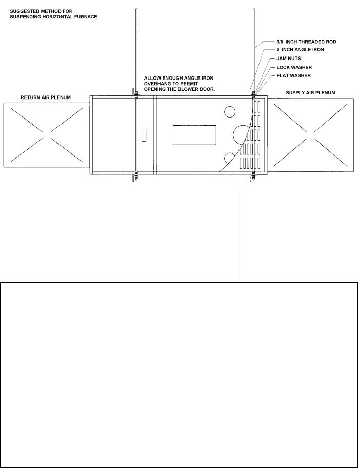
Fig. 1: Typical Suspended Application |
|
upright position. |
|
|
|
||||||||||
|
|
|
|
|
|
|
|
|
|
|||||||
|
|
|
|
|
|
|
|
|
|
|
|
|
|
|
|
|
3.Re-align the oil burner assembly to the combustion chamber (fire-pot), and then secure into place with the three nut and washer sets.
IMPORTANT: Model P3DHX12F08001 has an auxiliary limit control that must be in the upper position. Be sure that the auxiliary limit control is above the oil burner assembly.
NON-SUSPENDED INSTALLATION
Maintain clearances to combustibles as outlined in Table 1. Installation on a combustible floor requires a clearance of 1 inch. This can be done by using a noncombustible material such as one inch thick channel iron or similar material. The furnace must be supported in such a way as to not allow twisting or sagging of the cabinet. Suggestion; as a measure to prevent fuel oil from accumulating in locations other than the fire pot, as could be the case in the event of nozzle drip, install the furnace with an approximate 2 degree slope from the oil burner casing towards the fire pot. Use shims made of noncombustible material.
3

SUSPENDED INSTALLATION
Refer to Figure 1. Maintain clearances to combustibles as outlined in Table 1. The furnace may be suspended by field fabricating a cradle of angle iron and threaded rod. Secure the furnace with 2 inch minimum slotted angle or equivalent, as shown in Figure 1. The furnace must be supported in such a way as to not allow twisting or sagging of the cabinet. Position the supports so as to not interfere with accessing the burner and blower compartments. Suggestion; as a measure to prevent fuel oil from accumulating in locations other than the fire pot, as could be the case in the event of nozzle drip, install the furnace with an approximate 2 degree slope from the oil burner casing towards the fire pot.
AIR CONDITIONING
If the furnace is used in conjunction with air conditioning, the furnace shall be installed in parallel with or upstream from the evaporator coil to avoid condensation in the heat exchanger. In a parallel installation, the dampers or air controlling means must prevent chilled air from entering the furnace. If the dampers are manually operated, there must be a means of control to prevent the operation of either system unless the dampers are in the full heat or full cool position. The air heated by the furnace shall not pass through a refrigeration unit unless the unit is specifically approved for such service.
Generally, a six-inch clearance between the air conditioning evaporator coil and the heat exchanger will provide adequate airflow through the evaporator coil.
The blower speed must be checked and adjusted to compensate for the pressure drop caused by the evaporator coil. Refer to Appendix B for recommended wiring and electrical connections of the air conditioning controls.
COMBUSTION AIR
When a furnace is installed in the full basement of a typical frame or brick house, infiltration is normally adequate to provide air for combustion and draft operation. If the furnace is installed in a closet or utility room, two (2) ventilation openings must be provided connecting to a well ventilated space (full basement, living room or other room opening thereto, but not a bedroom or bathroom). One opening shall be located 6" from the top and bottom of the enclosure at the front of the furnace. For furnaces located in buildings of unusually tight construc-
tion, such as those with high quality weather stripping, caulking, windows and doors, or storm sashed windows, or where basement windows are well sealed, a permanent opening communicating with a well ventilated attic or with the outdoors shall be provided, using a duct if necessary. Size all of the openings and associated ductwork by the standards provided in the latest Oil Installation Code editions; NFPA 31 in the United States, CAN/CSA B139 in Canada. Take all fuel burning appliances in the area into consideration when calculating combustion and ventilation air requirements.
The Model CAS-2B-90E Furnace Boot manufactured by Field Controls, Inc. may be used with the furnace to obtain combustion air directly from outdoors. Use of this device does not alter the need for ventilation air; however, it does provide a good direct source of combustion air and is connected directly to the oil burner.
CHIMNEY VENTING
The chimney must be sized correctly and be in good repair. If the chimney is oversized, there is a high risk of the flue gases condensing resulting in damage to the chimney and other venting parts. This problem may be corrected by the use of an appropriately sized chimney liner.
If the chimney serves the P3DHX12F08001 furnace only, the vent should be sized at 4-inch minimum, 5- inch maximum. If the chimney serves the P2DHX16F12001 or P2LBX16F14501 furnace only, the vent should be sized at 4-inch minimum, 6-inch maximum. If the chimney serves the P4LBX20F19001 furnace only, the vent should be sized at 5-inch minimum, 7-inch maximum. The data provided in Table 3 is based on dedicated venting. If the furnace is to be co-vented with other appliances, refer to NFPA 211, Standard for Chimneys, Fireplaces, Vents, and Solid Fuel-Burning Appliances, NFPA 31, Standard for the Installation of Oil Burning Equipment or CAN/CSA B139, Installation Code For Oil Burning Equipment for correct sizing information.
NOTE:This furnace is approved for use with L-Vent.
NOTE:Maximum temperature for L- Vent is 575°F (300°C).
IMPORTANT: The chimney must be capable of providing sufficient draft at all times for the safe removal of the products of combustion.
The chimney should be tested under “winter” conditions; doors and windows closed, all other fossil fuel burning appliances on, clothes dryer on, bathroom fans on, etc. If the chimney cannot overcome the competition for air, it will be necessary to access the reason for it, and take corrective action. If the chimney is found to be sized correctly and in good repair, it will probably be necessary to reevaluate the availability of combustion and ventilation air, and take corrective action.
The flue pipe should be as short as possible with horizontal pipes sloping upward toward the chimney at a rate of one-quarter inch to the foot. The flue pipe should not be smaller in cross sectional area than the flue collar on the furnace. The flue pipe may be reduced in size to fit a smaller diameter chimney with the use of a tapered reducer fitting at the chimney inlet. The flue pipe should connect to the chimney such that the flue pipe extends into, and terminates flush with the inside surface of the chimney liner. Seal the joint between the pipe and the lining. The chimney outlet should be at least two feet above the highest point of a peaked roof. All unused chimney openings should be closed. Chimneys must conform to local, provincial or state codes, or in the absence of local regulations, to the requirements of the National Building Code.
See Figure 2 and Table 2 for common chimney problems and their remedies.
THE FURNACE MUST BE CONNECTED TO A FLUE HAVING SUFFICIENT DRAFT AT ALL TIMES TO ENSURE SAFE AND PROPER OPERATION OF THE APPLIANCE.
The flue pipe must not be routed through concealed space, because it must be visually checked for signs of deterioration during the annual inspection and servicing. The flue pipe must not pass through any floor or ceiling, but may pass through a wall where suitable fire protection provisions have been installed. In the United States, refer to the latest edition of NFPA 31 for regulations governing the installation of oil burning equipment. In Canada, refer to the latest edition of CAN/CSA B139 for rules governing the installation of oil burning equipment.
4

Fig. 2: Common Chimney Problems
Table 2: Common Chimney Problems
Refer to Figure 2
Key |
Trouble |
Diagnostic |
Remedy |
|
|
|
|
|
|
|
Top of chimney |
|
Extend chimney |
|
|
|
above all sur- |
||
A |
lower than sur- |
Observation |
||
rounding ob- |
||||
rounding ob- |
||||
|
|
jects within 30 |
||
|
jects |
|
||
|
|
feet. |
||
|
|
|
||
B |
Chimney Cap |
Observation |
Remove |
|
or ventilator. |
||||
|
|
|
||
|
Coping restricts |
|
Make opening |
|
C |
Observation |
as large as |
||
opening. |
inside of chim- |
|||
|
|
|||
|
|
|
ney. |
|
|
|
|
|
|
Obstruction in |
Can be found |
Use weight to |
|
|
by light and |
|||
D |
chimney |
|||
|
mirror reflecting |
break and dis- |
||
|
|
conditions in |
lodge. |
|
|
|
chimney. |
|
|
|
Joist protruding |
Lowering a light |
Must be han- |
|
E |
dled by compe- |
|||
on an extension |
||||
into chimney. |
tent masonry |
|||
|
cord. |
|||
|
|
contractor. |
||
|
|
|
||
|
|
|
|
|
|
|
Smoke test - |
|
|
|
|
build smudge |
Must be han- |
|
|
Break in chim- |
fire blocking off |
||
F |
dled by compe- |
|||
other opening, |
||||
ney lining. |
tent masonry |
|||
|
watching for |
|||
|
|
contractor. |
||
|
|
smoke to es- |
||
|
|
|
||
|
|
cape. |
|
|
|
|
|
|
|
|
Collection of |
|
Clean out with |
|
|
Lower light on |
weighted brush |
||
G |
soot at narrow |
|||
or bag of loose |
||||
space in flue |
extension cord. |
|||
|
gravel on end |
|||
|
opening. |
|
||
|
|
of line. |
||
|
|
|
||
|
|
|
|
|
H |
Offset |
Lower light on |
Change to |
|
straight or to |
||||
extension cord. |
||||
|
|
long offset. |
||
|
|
|
||
|
|
|
|
|
|
|
|
The least im- |
|
|
Two or more |
Found by in- |
portant opening |
|
I |
must be closed, |
|||
openings to the |
spection from |
|||
using some |
||||
|
same chimney. |
basement. |
||
|
other chimney |
|||
|
|
|
||
|
|
|
flue. |
|
|
|
|
|
|
|
Loose-seated |
|
Leaks should |
|
J |
Smoke test. |
be eliminated |
||
pipe in flue |
by cementing |
|||
|
opening. |
|
all pipe open- |
|
|
|
|
ings. |
|
|
|
Measurement |
Length of pipe |
|
|
Smoke pipe |
of pipe from |
must be re- |
|
|
within or obser- |
duced to allow |
||
K |
extends into |
|||
vation of pipe |
end of pipe to |
|||
|
chimney. |
|||
|
by means of a |
be flush with |
||
|
|
|||
|
|
lowered light. |
inside of tile. |
|
|
Failure to ex- |
By inspection or |
Extend partition |
|
L |
tend the length |
|||
of flue partition |
smoke test. |
to floor level. |
||
|
||||
|
to the floor. |
|
|
|
|
|
|
|
|
M |
Loose-fitted |
Smoke test. |
Close all leaks |
|
clean-out door. |
with cement. |
|||
|
|
DRAFT REGULATOR CONTROL
This device is used in conjunction with conventional chimney venting. This control (or draft regulator) automatically maintains a constant negative pressure in the furnace to obtain maximum efficiency. It ensures that proper pressures are not exceeded. If the chimney does not develop sufficient draft, the draft control cannot function properly. The draft regulator, must be installed within the same room or enclosure as the furnace, and should not interfere with the combustion air supplied to the burner. The control should be located a minimum of 3 flue pipe diameters from the furnace breeching and installed in accordance to the instructions supplied with the regulator.
5
Table 3: Minimum Chimney Base
Temperatures (°F)
Nozzle |
|
|
Chimney Height (ft.) |
|
||||
|
11 |
|
20 |
|
28 |
|
36 |
|
|
|
|
|
|
||||
Chimney Thermal Resistance < R6 |
||||||||
|
|
|
|
|
|
|
|
|
0.50 |
|
300 |
|
400 |
|
535 |
|
725 |
|
|
|
|
|
|
|
|
|
0.65 |
|
275 |
|
340 |
|
430 |
|
535 |
|
|
|
|
|
|
|
|
|
0.75 |
|
260 |
|
320 |
|
380 |
|
475 |
0.85 |
|
250 |
|
300 |
|
355 |
|
430 |
1.00 |
|
245 |
|
300 |
|
355 |
|
430 |
1.10 |
|
245 |
|
290 |
|
345 |
|
400 |
|
|
|
|
|
|
|
|
|
1.20 |
|
240 |
|
275 |
|
320 |
|
365 |
|
|
|
|
|
|
|
|
|
1.50 |
|
240 |
|
275 |
|
320 |
|
365 |
1.65 |
|
235 |
|
270 |
|
300 |
|
345 |
Nozzle |
|
|
Chimney Height (ft.) |
|
||||
|
|
|
|
|
|
|
|
|
|
11 |
|
20 |
|
28 |
|
36 |
|
|
|
|
|
|
||||
|
|
|
|
|
||||
Chimney Thermal Resistance > R6 |
||||||||
|
|
|
|
|
|
|
|
|
0.50 |
|
185 |
|
200 |
|
220 |
|
250 |
0.65 |
|
175 |
|
185 |
|
205 |
|
220 |
0.75 |
|
175 |
|
185 |
|
195 |
|
210 |
|
|
|
|
|
|
|
|
|
0.85 |
|
165 |
|
185 |
|
195 |
|
205 |
|
|
|
|
|
|
|
|
|
1.00 |
|
165 |
|
185 |
|
195 |
|
205 |
|
|
|
|
|
|
|
|
|
1.10 |
|
165 |
|
185 |
|
195 |
|
205 |
1.20 |
|
165 |
|
180 |
|
190 |
|
200 |
1.50 |
|
165 |
|
175 |
|
185 |
|
195 |
|
|
|
|
|
|
|
|
|
1.65 |
|
165 |
|
175 |
|
180 |
|
190 |
|
|
|
|
|
|
|
|
|
< - less than, |
> - greater than |
|
|
|
||||
|
|
|
|
|
|
|
|
|
OIL TANK
Oil storage tanks must be selected and installed in compliance with applicable codes; in the United States, NFPA 31,
Standard for the Installation of Oil Burning Equipment, Chapter 2. and in Canada, CAN/CSA-B139, Installation Code for Oil Burning Equipment, Section 6. Observe all local codes and by-laws.
In general, the oil tank must be properly supported and remain stable in both empty and full condition. The oil tank must be fitted with vent and supply pipes to the outdoors. Refer to the abovementioned codes for sizing. The vent pipe must be no less than 1¼ inches I.P.S., and terminate with an appropriate vent cap in a location where it will not be blocked. The fill pipe must be no less than 2 inches I.P.S., and terminate with an appropriate cap in a location where debris will not enter the fill pipe during oil delivery.
If located indoors, the tank should normally be in the lowest level, (cellar, basement, etc.). It must be equipped with a shut-off valve at the tank outlet used for the oil supply. The oil tank must be located as to not block the furnace / room exit pathway. Observe all clearances specified in the above-mentioned codes.
PIPING INSTALLATION
In the United States, NFPA 31, Standard for the Installation of Oil Burning Equipment, Chapter 2.
In Canada, the entire fuel system should be installed in accordance with the requirements of CAN/CSA B139, and local regulations. Use only approved fuel oil tanks piping, fittings and oil filters.
Ensure that all fittings used in a copper oil line system are high quality flare fittings. Do not use compression fittings.
Do not use Teflon tape on any fittings.
Pressurized or gravity feed installations must not exceed 3 PSIG. Pressures greater than 10 PSIG may cause damage to the shaft seal. If the height of the oil stored in a tank above the oil burner exceeds 11½ feet, it may be necessary to use a pressure-regulating device approved for this purpose.
The furnace may be installed with a onepipe system with gravity feed or lift. The maximum allowable lift on a single line system is 8 feet. Lift should be measured from the bottom (outlet) of the tank, to the inlet of the burner. Sizing a single line system is complex because of the difficulty estimating the pressure drop through each fitting, bend and component in the line. In general, keep single line systems short as possible. 2-stage oil pumps are not available for either the P*HMX or P*LBX furnaces. The following chart shows the allowable line lengths (horizontal + vertical) for single and twoline oil piping systems. All distances are in feet.
Table 4: Oil Lines
Copper Tubing Oil Line Length (Feet)
Single-Pipe Two-Pipe
Lift |
|
|
|
|
⅜” |
|
⅜” |
|
|
(Feet) |
½” OD |
½” OD |
||
|
OD |
|
OD |
|
0 |
53 |
100 |
68 |
100 |
1 |
49 |
100 |
65 |
100 |
|
|
|
|
|
2 |
45 |
100 |
63 |
100 |
|
|
|
|
|
3 |
41 |
100 |
60 |
100 |
|
|
|
|
|
4 |
37 |
100 |
58 |
100 |
|
|
|
|
|
Continue
5 |
33 |
100 |
55 |
100 |
6 |
29 |
100 |
53 |
100 |
|
|
|
|
|
7 |
25 |
99 |
50 |
100 |
|
|
|
|
|
8 |
21 |
83 |
48 |
100 |
9 |
17 |
68 |
45 |
100 |
|
|
|
|
|
10 |
13 |
52 |
42 |
100 |
|
|
|
|
|
12 |
- - - |
- - - |
37 |
100 |
|
|
|
|
|
14 |
- - - |
- - - |
32 |
100 |
16 |
- - - |
- - - |
27 |
100 |
|
|
|
|
|
18 |
- - - |
- - - |
22 |
88 |
|
|
|
|
|
In retrofit applications, where an existing oil line system is in place, a vacuum check will help determine the efficacy of the existing oil line system The vacuum in a system should not exceed 6” Hg. for a single pipe system, nor 12” Hg. for a two-pipe system.
NOTE: The oil burner requires the use of a bypass plug when converting from single-pipe to two-pipe oil piping systems. See burner manufacturer’s instructions.
All fuel systems should include an oil filter between the fuel oil storage tank and the oil burner. For best results, install the oil filter as close to the burner as possible. When using an indoor oil tank, the oil filter may be installed at the tank downstream from the shut-off valve. If firing the furnace under the 0.65 gph rate, a 7 to 10 micron line filter should be installed as close to the oil burner as possible.
ELECTRICAL CONNECTIONS
The furnace is listed by the Canadian Standards Association (CSA). All models except for the P4LBX20F19001 are factory wired and require minimal field wiring. The P4LBX20F19001 model is prewired except for the wiring connections to the blower motor. The wires from the furnace section are routed through the grommet in the blower section blower division panel, and then connected to the blower motor. In the United States, the wiring must be in accordance with the National Fire Protection Association NFPA-70, National Electrical Code, and with local codes and regulations. In Canada, all field wiring should conform to CAN/CSA C22.1 Canadian Electrical Code, Part 1, and by local codes, where they prevail.
The furnace should be wired to a separate and dedicated circuit in the main electrical panel; however, accessory equipment such as electronic air clean-
6

ers and humidifiers may be included on the furnace circuit. Although a suitably located circuit breaker can be used as a service switch, a separate service switch is advisable. The service switch is necessary if reaching the circuit breaker involves becoming close to the furnace, or if the furnace is located between the circuit breaker and the means of entry to the furnace room. The furnace switch (service switch) should be clearly marked, installed in an easily accessible area between the furnace and furnace room entry, and be located in such a manner to reduce the likelihood that it would be mistaken as a light switch or similar device.
The power requirements for all models: 120 VAC, 1 , 60 Hz.
Maximum fuse size for the P*DHX models and P2LBX16F14501 model: 15 amps. Maximum fuse size for the P4LBX20F19001 model: 20 amps.
Accessories requiring 120 VAC power sources such as electronic air cleaners and humidifier transformers may be powered from the furnace circuit. Do not use the direct drive motor connections as a power source, since there is a high risk of damaging the accessories by exposure to high voltage from the autogenerating windings of the direct drive motor.
Thermostat wiring connections and air conditioning contactor low voltage connections are shown in the wiring diagrams. Some micro-electronic thermostats require additional controls and wiring. Refer to the thermostat manufacturer's instructions.
The thermostat should be located approximately 5 feet above the floor, on an inside wall where there is good natural air circulation, and where the thermostat will be exposed to average room temperatures. Avoid locations where the thermostat will be exposed to cold drafts, heat from nearby lamps and appliances, exposure to sunlight, heat from inside wall stacks, etc.
Normal heat anticipator setting: for the P*LBX models is 0.1 A. Normal heat anticipator setting: for the P*DHX models is 0.4 A .For more precise adjustment, the heat anticipator may be adjusted to the amperage draw of the heating control circuit as measured between the "R" and "W" terminals of the thermostat. To reduce the risk of damaging the heat anticipator, do not measure circuit without first removing one of the two wires first.
To determine the heating circuit amperage draw:
1.Disconnect one of the “R” or “W” wires from the thermostat terminal.
2.Connect an ammeter between the wire and the thermostat terminal to which it was attached.
3.Note the amperage reading when the heating contacts are closed. (System switch must be on “HEAT” if so equipped.
4.Re-connect the thermostat wire. If the thermostat is serving a combination heating and air conditioning system, pay particular attention to polarity.
5.When the thermostat is reconnected and re-plumbed, adjust the heat anticipator setting to match the observed amperage reading.
CIRCULATING AIR BLOWER
Both P*DHX and the P2LBX16F14501 furnace models are equipped with a direct drive blower system. Direct drive blower speed adjustments are not normally required in properly sized extended plenum duct systems. The motor RPM and air CFM delivery will vary automatically to accommodate conditions within the usual range of external static pressures typical of residential duct systems. Under-sized duct systems may require a higher blower speed to obtain a reasonable system temperature rise. Some older duct systems were not designed to provide static pressure. They typically feature special reducing fittings at each branch run and lack block ends on the trunk ducts. These systems may require modification to provide some resistance to the airflow to prevent overamping of the direct drive blower motor. Selecting a lower blower speed may correct this problem.
Direct drive blower speeds are adjusted by changing the "hot" wires to the motor winding connections. Please refer to wiring diagram in Appendix B or the wiring diagram label affixed to the furnace.
THE NEUTRAL WIRE (normally the white wire) IS NEVER MOVED TO ADJUST THE BLOWER SPEED.
DO NOT CONNECT POWER LEADS BETWEEN MOTOR SPEEDS. THE NEUTRAL WIRE MUST ALWAYS BE CONNECTED TO THE MOTOR'S DESIGNATED NEUTRAL TERMINAL.
It is possible and acceptable to use a single blower speed for both heating and cooling modes. The simplest method to connect the wiring from both modes is to use a "piggy-back connector" accommodating both wires on a single motor tap. It is also acceptable to connect the selected motor speed with a pigtail joined to both heating and cooling speed wires with a wire nut. As a safety precaution against accidental disconnection of the wires by vibration, it is advisable to secure the wire nut and wires with a few wraps of electricians tape.
If the joining of the blower speed wiring is done in the furnace junction box, tape off both ends of the unused wire.
The P4LBX20F19001 furnace model is equipped with a belt drive blower system. The blower speed (RPM) and resultant airflow can be varied by adjusting the variable speed motor pulley.
DISCONNECT THE POWER SUPPLY TO THE FURNACE BEFORE OPENING THE BLOWER ACCESS DOOR TO SERVICE THE AIR FILTER, FAN AND MOTOR. FAILURE TO SHUT OFF POWER COULD ALLOW THE BLOWER TO START UNEXPECTEDLY, CREATING A RISK OF DEATH OR PERSONAL INJURY.
Do not use the blower speed wires as a source of power to accessories as electronic air cleaners and humidifier transformers. The unused motor taps auto-generate sufficiently high voltages to damage accessory equipment.
Do not start the burner or blower fan unless the blower access door is securely in place.
7

OIL BURNER
P*LBX furnaces are equipped with Beckett AF Series oil burners with the Beckett CleanCut pump and R7184B oil primary control. P*DHX furnaces are equipped with Beckett AF Series oil burners with the R8184N oil primary control. The oil burner must align properly with the cerafelt fiber chamber (firepot). The cerafelt fiber chamber is initially quite soft, but hardens and becomes quite brittle after the first firing. The firepot is held in place by a retaining bracket; however, it is possible for the firepot to shift if subjected to rough handling during transit.
BEFORE OPERATING THE FURNACE CHECK BURNER ALIGNMENT WITH COMBUSTION CHAMBER. THE END CONE OF THE AIR TUBE MUST BE CENTRED TO THE ACCOMODATING RING PROVIDED IN THE DESIGN OF THE COMBUSTION CHAMBER. ADJUST ALIGNMENT AS NECESSARY BEFORE THE FIRST FIRING.
OIL BURNER NOZZLES
All furnace models are certified for multiple firing rates. Choose the firing rate that most closely matches the calculated heat loss of the building. Models, firing rates and nozzles are listed in Appendix A: AF Burner Set-Up.
BURNER ELECTRODES
Correct positioning of the electrode tips with respect to each other, to the fuel oil nozzle, and to the rest of the burners is essential for smooth light ups and proper operation. The electrode tips should be adjusted to a gap of 5/32”, 1/16” ahead of the nozzle, 5/16” above the centerline of the nozzle. The “Z” dimension (front edge of the burner head to the front face of the nozzle is 1-1/8 inches.
Electrode positioning should be checked before the first firing of the furnace.
The electrode porcelains should be free of cracks, the electrode tips should be tapered and free of burrs, and the contact rods must be clean and be in firm contact with the ignition transformer contact springs. The electrodes must not come into contact with the burner head.
OIL BURNER SET-UP
The burner air supply is adjusted to maintain the fuel to air ratio to obtain ideal combustion conditions. A lack of air causes "soft" and "sooty" flames, resulting in soot build-up throughout the heat exchanger passages. Excess combustion air causes a bright roaring fire and high stack temperatures resulting in poor fuel efficiency.
PREPARATIONS:
Drill a ¼” test port in the venting, ideally at least 2 flue pipe diameters away from the furnace breeching, if venting horizontally from the furnace, (typically P*LBX) or from the flue pipe elbow if venting vertically (typically P*DHX) before reaching the furnace. (see Figures 4 and 5).
The test port will allow flue gas samples to be taken and stack temperatures to be measured.
Before starting the burner, check the burner alignment with the combustion chamber (fire pot), check that the correct nozzle is tightened into place, and that the burner electrodes are properly positioned.
The Beckett burner bulk air band should be closed, and the air shutter initial setting should be approximately 7.00.
Note A: Locate hole at least 6 inches on the furnace side of the draft control.
Note B: Ideally, hole should be at least 12 inches from breeching or elbow.
PROCEDURE:
Start the burner and allow it to run at least ten minutes. Set the air shutter to give a good flame visually. The combustion air supply to the burner is controlled by adjusting the air shutter on the left side of the burner, and, if necessary, the bulk air band. To adjust, loosen the bolt on the movable shutter. Move the shutter gradually until a good flame (visually) has been achieved. Re-snug the bolt.
Check the initial draft setting as the furnace warms up. The draft may be measured at the test port. The final breech draft should be - 0.02 inches w.c. to provide adequate over-fire draft.
Fig. 4: Horizontal Smoke Test Port Location |
|
Fig. 5: Vertical Smoke Test Port Location |
|
||||||
|
|
|
|
|
|
|
|
|
|
|
|
|
|
|
|
|
|
|
|
8

Check the oil pump pressure. Standard operating pressure is 100 PSIG.
After reaching steady state, take a smoke test. If not indicating a trace, set the combustion air controls to provide a trace.
Typically, the CO2 reading will range from 11.5% to 13.5%.
After the air adjustments have been completed, and the air shutter or air adjustment plate has been secured, recheck the breech draft and take another smoke test to ensure that the values have not changed.
SMOKE TEST NOTE:
If oily or yellow smoke spots are found on the smoke test filter paper, it is usually a sign of unburned fuel. This indicates poor combustion. This type of problem may be caused by excess draft, excess air, or contaminated fuel. Do not ignore this indicator.
STACK TEMPERATURE:
Stack temperature will vary depending on fuel input, circulating air blower speed, and burner set up, etc. In general, stack temperature should typically range between 380°F to 550°F, assuming that the combustion air is approximately room temperature (65°F - 70°F). In general, lower stack temperature indicates greater efficiency; however, excessively low stack temperature can lead to condensation forming in the chimney and / or venting. Sulphur and similar contaminants in the fuel oil will mix with condensation to form acids. Acids and resultant chemical salts will cause rapid deterioration of the chimney and venting components, and may attack the furnace.
If the flue gases are below the range, it may be necessary to slow down the blower fan. If the flue gases are above the range, the blower fan may require speeding up. Stack temperature varies directly with the system temperature rise. System temperature rise is the difference between the furnace outlet temperature and furnace inlet temperature as measured in the vicinity of the connection between the plenum take-offs and the trunk ducts. Typical temperature rise values range between 70°F and 85°F.
If the venting from the furnace to the chimney is long, or exposed to cold ambient temperatures, it may be necessary to use L-Vent as the vent connector to reduce stack temperature loss to prevent condensation. The venting should be inspected annually to ensure that it is intact.
FURNACE INSTALLATION SET-UP
The furnace must be set up as the final step in the installation.
A)The oil burner must be set up following the procedures outlined above.
B)The furnace should operate within a temperature rise of 85°F ±15°F. To determine the temperature rise, measure the supply air and return air temperatures when the furnace has reached steady state conditions. This is the point at which the supply air temperature stops increasing relative to the return air temperature. The furnace may have to run 10 to 15 minutes to reach steady state conditions. The measurements may be made with duct thermometers or thermocouples used in conjunction with multimeters with temperature measurement capabilities.
The return air should be measured at a point where the thermometer will be well within the air stream near the furnace return air inlet. Actual location is not particularly critical; however, avoid locations where the temperature readings could be affected by humidifier bypass ducts, the inside radius of elbows, etc.
The supply air temperature should be measured at a point where the thermometer will be well within the air stream near the furnace supply air outlet. Usually, the side mid-point of the supply air plenum take-off is ideal, providing it is out of the line of sight to the heat exchanger. If the thermometer is within the line of sight of the heat exchanger, the supply air readings may be skewed by radiant heat from the heat exchanger. If the plenum take-off is unsuitable, the supply air temperature may be measured within the first 18 inches of the first segment of supply air trunk duct.
If the temperature rise is outside the recommended range, it may be adjusted on direct drive equipped units by selecting alternate circulation fan motor speeds, on belt drive equipped units by adjusting the variable speed motor pulley. If the temperature rise is too high, speed the fan up. If the temperature rise is too low, slow the fan down.
C) Keep in mind that the stack temperature varies directly with the temperature rise. The higher the temperature rise, the higher the stack temperature will be, resulting in lower efficiency. The lower the temperature rise, the lower the stack temperature will be, which, in some cases, may allow condensation to form in the chimney and other vent parts.
D)Test the high limit control to ensure that it is operating correctly. For direct drive equipped units, this may be done by temporarily removing the circulator fan heating wire or neutral wire. For belt drive equipped units, temporarily remove the fan belt. Turn of electrical power to the furnace before working with the motor wires or fan belt. Be sure to protect any removed wires from shorting out on metal furnace parts. If the high limit test is successful, shut off the electrical power to the furnace, restore the proper motor wiring. Finally, restore power to the furnace.
E)Adjust the “Fan Off” setting on the L6064A or L4064W fan limit controller. In most cases, the “Fan Off” temperature should be 90° to 100°F as indicated on the thermometer used to measure the supply air temperature. Once the “Fan Off” setting has been established, set the “Fan On” setting. In most cases, the “Fan On” setting should be approximately 30°F higher than the Fan Off” setting.
NOTE: The L4064W fan/limit controller has an auxiliary “fan on” function that activates when the thermostat is calling for heat. The controller is designed to start the circulating fan in 20 to 30 seconds. Adjust the “fan on” setting on the controller dial 30°F higher than the “fan off” setting even though the circulating fan will normally be started by the auxiliary “fan on” function.
F)Operate the furnace through a minimum of three full heating cycles. During this time, check for fuel oil leaks, gross air leakage from the supply air ductwork, unusual noises originating anywhere within the heating system which may cause some concern or annoyance to the home owner, etc.
G)Be sure that the homeowner is familiar with the furnace. The homeowner should be aware of the location of electrical circuit breaker or fuse, the location of any electrical switches controlling the furnace, the location of the oil tank shut-off valve and how to operate the valve. The homeowner should be informed where the oil tank gauge is located and how to read it.
It would be beneficial to review safety issues with the home owner, such as the danger of storing combustibles too close to the furnace, hanging anything on the furnace vent pipe, and especially the dangers of indiscriminately pressing the burner reset button.
9

IMPORTANT: Be sure that the home owner knows where the burner reset switch is located, and is aware that the reset switch is not to be activated more than once without a thorough look for the cause of the problem, (lack of fuel, etc.). Be sure that the homeowner knows when to quit trying to start the furnace during these conditions and who to call for emergency service.
MAINTENANCE AND SERVICE
A: Routine Maintenance By Home
Owner
Other than remembering to arrange for the annual professional servicing of the furnace by the service or installation contractor, the most important routine service performed by the homeowner is to maintain the air filter or filters. A dirty filter can cause the furnace to over-heat, fail to maintain indoor temperature during cold weather, increase fuel consumption and cause component failure.
The furnace filter(s) should be inspected, cleaned or replaced monthly. The furnace is factory equipped with a semipermanent type filter. If the filter is damaged, replace with filters of the same size and type.
During the routine service, inspect the general condition of the furnace watching for signs of oil leaks in the vicinity of the oil burner, soot forming on any external part of the furnace, soot forming around the joints in the vent pipe, etc. If any of these conditions are present, please advice your service or installation contractor.
B: Annual Service By Contractor
THE Combustion chamber (firepot) IS FRAGILE. use care when inspecting and cleaning this area.
The heat exchanger should be inspected periodically and cleaned if necessary. if cleaning is necessary, SHUT OFF POWER TO THE FURNACE and remove the burner. Using a stiff brush with a wire handle, brush off scale and soot from inside the drum and flue pipe. To clean the heat exchanger radiator, remove the covers on the front or inner front panel, and then loosen the brass nuts on the radiator clean-out yoke assembly. Do not remove the brass nuts. The yoke assembly, once loosened, may be removed to gain access to the heat exchanger outer radiator.
A wire brush can be used to loosen dirt and debris on the inside surfaces of the radiator. Clean out all accumulated dirt, soot and debris with a wire handled brush and an industrial vacuum cleaner. Replace the clean-out yoke assemblies and clean-out covers.
Most circulating fan motors are permanently lubricated by the motor manufacturer. These motors will have no oil ports. If the blower motor does contain oil ports, under normal operating conditions it will not require oiling for the first two years. Oil sparingly; a few drops in each oil port with SAE 20 non-detergent oil. Oiling is most easily done with a "tele-spout" oiler. This oiler has a long flexible plastic spout. DO NOT OVERLUBRICATE. Excess oil may result in premature electric motor failure.
Inspect the blower fan. Clean it if necessary.
Oil Burner Maintenance: Follow the instructions of the oil burner manufacturer. (See oil burner manufacturer's instructions supplied with furnace). The oil burner nozzle should be replaced annually. We recommend that the oil filter be changed on an annual basis.
The venting system should be cleaned and inspected for signs of deterioration. Replace pitted or perforated vent pipe and fittings. The barometric draft regulator should open and close freely.
All electrical connections should be checked to ensure tight connections. Safety controls such as the high limit controls should be tested for functionality. The fan control functions should be checked to ensure that all fan speeds are operating properly.
OPERATING INSTRUCTIONS
Before Lighting
Open all supply and return air registers and grilles.
Open all valves in oil pipes.
Turn on electric power supply.
To Light Unit
Set the thermostat above room temperature to call for heat. The burner will start. NOTE: If the furnace has been off for an extended period of time, it may be necessary to press the RESET button on the primary combustion control relay, (once only). If pressing the reset button does not start the furnace, refer to Appendix C, Troubleshooting.
After the furnace warms sufficiently, the circulation fan will start.
The furnace will continue to run until the thermostat call for heat is satisfied.
Set the thermostat below room temperature. The oil burner will stop.
The air circulation blower will continue to run until the furnace has cooled sufficiently.
To Shut Down Unit
Set the thermostat to the lowest possible setting. Set the manual switch (if installed) in the Electrical Power Supply Line to "OFF".
NOTE: If the furnace is to be shut down for an extended period of time, close the oil supply valve to the oil burner.
DO NOT ATTEMPT TO START THE BURNER WHEN EXCESS OIL HAS ACCUMULATED, WHEN THE FURNACE IS FULL OF VAPOUR, OR WHEN THE COMBUSTION CHAMBER IS VERY HOT. NEVER BURN GARBAGE OR PAPER IN THE FURNACE, AND NEVER LEAVE PAPER OR RAGS AROUND THE UNIT.
10
TABLE A-1: BECKETT OIL BURNER SET-UP
BECKETT AF SERIES OIL BURNERS
FURNACE |
OUTPUT |
BURNER |
NOZZLE |
PUMP |
FLOW |
HEAD |
STATIC |
|
MODEL |
BTU/Hr. |
MODEL |
(Delavan) |
PRESSURE |
RATE |
PLATE |
||
|
||||||||
|
|
|
|
|
|
|
|
|
|
|
|
|
|
|
|
|
|
|
60,000 3 |
AF76BNHS |
0.50 / 80°A |
100 PSIG |
0.50 GPH |
F3 1 |
3-3/8 in. |
|
P3DHX12F08001 |
78,000 2 |
AF76BNHS |
0.65 / 80°A |
100 PSIG |
0.65 GPH |
F3 1 |
3-3/8 in. |
|
|
90,000 |
AF76BNHS |
0.75 / 80°A |
100 PSIG |
0.75 GPH |
F3 1 |
3-3/8 in. |
|
|
|
|
|
|
|
|
|
|
|
91,000 |
AF76XN |
0.75 / 80°A |
100 PSIG |
0.75 GPH |
F3 |
2-3/4 in. |
|
|
|
|
|
|
|
|
|
|
P2DHX16F12001 |
101,000 |
AF76XN |
0.85 / 80°A |
100 PSIG |
0.85 GPH |
F3 |
2-3/4 in. |
|
|
|
|
|
|
|
|
||
117,000 2 |
AF76XN |
1.00 / 60°A |
100 PSIG |
1.00 GPH |
F3 |
2-3/4 in. |
||
|
||||||||
|
128,000 |
AF76YB |
1.10 / 70°A |
100 PSIG |
1.10 GPH |
F6 |
2-3/4 in. |
|
|
|
|
|
|
|
|
|
|
|
|
|
|
|
|
|
|
|
P2LBX16F14501 |
130,000 |
AF65YB |
1.10 / 70°A |
100 PSIG |
1.10 GPH |
F6 |
2-3/4 in. |
|
|
|
|
|
|
|
|
||
143,000 2 |
AF65YB |
1.20 / 60°A |
100 PSIG |
1.20 GPH |
F6 |
2-3/4 in. |
||
|
||||||||
|
|
|
|
|
|
|
|
|
P4LBX20F19001 |
168,000 |
AF81WF |
1.50 / 70°B |
100 PSIG |
1.50 GPH |
F16 |
2-3/4 in. |
|
|
|
|
|
|
|
|
||
188,000 2 |
AF81WF |
1.65 / 70°B |
100 PSIG |
1.65 GPH |
F16 |
2-3/4 in. |
||
|
1 Used with ceramic insulator.
2 Factory supplied nozzle.
3 Requires a low firing rate baffle.
In the United States, the R. W. Beckett “AF” Burner may be equipped with Beckett’s “Inlet Air Shut-Off”, Beckett Part No. AF/A 5861, to increase efficiency. It reduces the amount of air passing through the oil burner, combustion chamber, breeching, etc. up the chimney between burner cycles.
NOTE: THE USE OF THIS CONTROL CAN OCCASIONALLY CAUSE POST COMBUSTION NOZZLE DRIP.
11
 Loading...