


TECHNICAL GUIDE
246721-YTG-C-0606
®
MagnaDRY™
SINGLE PACKAGE AIR CONDITIONERS AND SINGLE PACKAGE GAS/ELECTRIC UNITS
DR090, 120 and 150
DR090, 120
DR150
DESCRIPTION
ASHRAE 90.1 COMPLIANT
YORK® Predator® MagnaDry™ units are convertible single packages with a common footprint cabinet and common roof curb for all 7-1/2 through 12-1/2 ton models. All units have two compressors with independent refrigeration circuits to provide 2 stages of cooling. The units were designed for light commercial applications and can be easily installed on a roof curb, slab, or frame.
All Predator® MagnaDry™ units are self-contained and assembled on rigid full perimeter base rails allowing for 3-way forklift access and overhead rigging. Every unit is completely charged, wired, piped, and tested at the factory to provide a quick and easy field installation.
All units are convertible between side and down airflow. Independent economizer designs are used on side and down discharge applications, as well as all tonnage sizes.
Predator® MagnaDry™ units are available in the following configurations: cooling only, cooling with electric heat, and cooling with gas heat. Electric heaters are available as fac- tory-installed options or field-installed accessories.
The Predator® MagnaDry™ provides energy-savings, efficient removal of moisture through a balanced coil design. Because the unit doesn’t increase sensible cooling, it allows temperatures to be maintained within the comfort zone. Unlike competitive systems, you’re not subjected to over cooling. You save through more efficient matching of dehumidification and cooling needs. This makes the MagnaDry™ perfect for applications that need to remove large amounts of moisture or maintain low humidity levels.
Tested in accordance with:
FOR DISTRIBUTION USE ONLY - NOT TO BE USED AT POINT OF RETAIL SALE
246721-YTG-C-0606
TABLE OF CONTENTS
DESCRIPTION . . . . . . . . . . . . . . . . . . . . . . . . . . . . . . . . . . . . . 1 FEATURES . . . . . . . . . . . . . . . . . . . . . . . . . . . . . . . . . . . . . . . . 5 FACTORY INSTALLED OPTIONS. . . . . . . . . . . . . . . . . . . . . 6
FIELD INSTALLED ACCESSORIES . . . . . . . . . . . . . . . . . . . 8
REHEAT MODE SEQUENCE OF OPERATION. . . . . . . . . . 9 NOMENCLATURE . . . . . . . . . . . . . . . . . . . . . . . . . . . . . . . . . 14 GUIDE SPECIFICATIONS . . . . . . . . . . . . . . . . . . . . . . . . . . 62
LIST OF FIGURES
Fig. # |
Pg. # |
1 PREDATOR® MAGNADRY™ DR090, 120 . . . . . . . . . . . . 4 2 PREDATOR® MAGNADRY™ DR150 . . . . . . . . . . . . . . . . 5 3 REHEAT CONTROL BOARD . . . . . . . . . . . . . . . . . . . . . . 10 4 DR090 & 120 REHEAT CONTROLS . . . . . . . . . . . . . . . . 11 5 DR150 REHEAT CONTROLS. . . . . . . . . . . . . . . . . . . . . . 12 6 DR090 MOISTURE REMOVAL - ALTERNATE MODE . . 23 7 DR090 MOISTURE REMOVAL - NORMAL MODE . . . . . 23 8 DR120 MOISTURE REMOVAL - ALTERNATE MODE . . 24 9 DR120 MOISTURE REMOVAL - NORMAL MODE . . . . . 24
10 DR150 MOISTURE REMOVAL - ALTERNATE MODE . . 25 11 DR150 MOISTURE REMOVAL - NORMAL MODE . . . . . 25 12 DR090, 120 UNITS 4 POINT LOAD . . . . . . . . . . . . . . . . . 42 13 DR090, 120 UNITS 6 POINT LOAD . . . . . . . . . . . . . . . . . 42 14 UNIT CENTER OF GRAVITY DR090, 120 . . . . . . . . . . . . 42 15 DR150 UNIT 4 POINT LOAD . . . . . . . . . . . . . . . . . . . . . . 42 16 DR150 UNIT 6 POINT LOAD . . . . . . . . . . . . . . . . . . . . . . 42 17 UNIT CENTER OF GRAVITY DR150 . . . . . . . . . . . . . . . . 42 18 DR090/120 UNIT DIMENSIONS . . . . . . . . . . . . . . . . . . . . 43 19 DR150 UNIT DIMENSIONS . . . . . . . . . . . . . . . . . . . . . . . 44 20 PREDATOR® ROOF CURB DIMENSIONS . . . . . . . . . . . 45
21 SUNLINE™ TO PREDATOR® TRANSITION
ROOF CURBS. . . . . . . . . . . . . . . . . . . . . . . . . . . . . . . . . . 45 22 BOTTOM DUCT OPENINGS (FROM ABOVE) . . . . . . . . 46 23 DR090, 120 REAR DUCT DIMENSIONS . . . . . . . . . . . . . 46 24 DR150 REAR DUCT DIMENSIONS . . . . . . . . . . . . . . . . . 47 25 DOWNFLOW ECONOMIZER HOOD DETAIL . . . . . . . . . 47 26 DOWNFLOW ECONOMIZER HOOD DETAIL . . . . . . . . . 48 27 FACTORY INSTALLED DOWNFLOW ECONOMIZER . . 49
28 FIELD INSTALLED DOWNFLOW ECONOMIZER W/POWER EXHAUST. . . . . . . . . . . . . . . . . . . . . . . . . . . . 49
29 FIELD INSTALLED HORIZONTAL ECONOMIZER W/POWER EXHAUST. . . . . . . . . . . . . . . . . . . . . . . . . . . . 50
30 SLAB ECONOMIZER DOWNFLOW W/POWER
EXHAUST . . . . . . . . . . . . . . . . . . . . . . . . . . . . . . . . . . . . . 50
31 SLAB ECONOMIZER END RETURN W/POWER EXHAUST . . . . . . . . . . . . . . . . . . . . . . . . . . . . . . . . . . . . . 51
32 TYPICAL LOW VOLTAGE FIELD WIRING . . . . . . . . . . . 52
33 FIELD WIRING DISCONNECT-COOLING UNIT WITH/ WITHOUT ELECTRIC HEAT . . . . . . . . . . . . . . . . . . . . . . 53
34 FIELD WIRING DISCONNECT-COOLING UNIT
WITH GAS HEAT . . . . . . . . . . . . . . . . . . . . . . . . . . . . . . . 53
35 DR090, 120 COOLING UNIT WITH GAS HEAT
WIRING 230 VOLT DIAGRAM . . . . . . . . . . . . . . . . . . . . . 54
36 DR150 COOLING UNIT WITH GAS HEAT
WIRING 230 VOLT DIAGRAM . . . . . . . . . . . . . . . . . . . . . 55
37 DR090, 120 COOLING UNIT WITH/WITHOUT
ELECTRIC HEAT WIRING DIAGRAM . . . . . . . . . . . . . . . 56
38 DR150 COOLING UNIT WITH/WITHOUT ELECTRIC HEAT WIRING DIAGRAM . . . . . . . . . . . . . . . . . . . . . . . . 57
39 DR090, 120 COOLING UNIT WITH GAS HEAT WIRING 460, 575 VOLT 50 HZ DIAGRAM . . . . . . . . . . . . . . . . . . . 58
40 DR150 COOLING UNIT WITH GAS HEAT WIRING
460, 575 & 50 HZ DIAGRAM . . . . . . . . . . . . . . . . . . . . . . 59 41 DR090 AND 120 REHEAT WIRING DIAGRAM . . . . . . . . 60 42 DR150 REHEAT WIRING DIAGRAM. . . . . . . . . . . . . . . . 61
LIST OF TABLES
Tbl. # |
Pg. # |
1 ACCESSORIES . . . . . . . . . . . . . . . . . . . . . . . . . . . . . . . . 13
2 PHYSICAL DATA . . . . . . . . . . . . . . . . . . . . . . . . . . . . . . . 15
3 DR CAPACITY RATINGS. . . . . . . . . . . . . . . . . . . . . . . . . 16
4 UNIT VOLTAGE LIMITATIONS . . . . . . . . . . . . . . . . . . . . 16
5 COOLING CAPACITY DR090 UNIT . . . . . . . . . . . . . . . . 17
6 COOLING CAPACITY DR090 UNIT
(ALTERNATE REHEAT MODE). . . . . . . . . . . . . . . . . . . . 18
7 COOLING CAPACITY DR120 UNIT . . . . . . . . . . . . . . . . 19
8 COOLING CAPACITY DR120 UNIT
(ALTERNATE REHEAT MODE). . . . . . . . . . . . . . . . . . . . 20
9 COOLING CAPACITY DR150 UNIT . . . . . . . . . . . . . . . . 21
10 COOLING CAPACITY DR150 UNIT
(ALTERNATE REHEAT MODE). . . . . . . . . . . . . . . . . . . . 22
11 ELECTRICAL DATA DR090 W/O PWRD
CONVENIENCE OUTLET . . . . . . . . . . . . . . . . . . . . . . . . 26
12 ELECTRICAL DATA DR090 WITH PWRD
CONVENIENCE OUTLET . . . . . . . . . . . . . . . . . . . . . . . . 26
13 ELECTRICAL DATA DR120 W/O PWRD
CONVENIENCE OUTLET . . . . . . . . . . . . . . . . . . . . . . . . 27
2 |
Unitary Products Group |
246721-YTG-C-0606
14 ELECTRICAL DATA DR120 WITH PWRD
CONVENIENCE OUTLET . . . . . . . . . . . . . . . . . . . . . . . . . 27
15 ELECTRICAL DATA DR150 W/O PWRD
CONVENIENCE OUTLET . . . . . . . . . . . . . . . . . . . . . . . . . 28
16 ELECTRICAL DATA DR150 W/PWRD |
|
CONVENIENCE OUTLET . . . . . . . . . . . . . . . . . . . . . . . . . |
28 |
17 ELECTRIC HEAT MULTIPLIERS . . . . . . . . . . . . . . . . . . . 28
18 BLOWER PERFORMANCE DR090 SIDEFLOW . . . . . . . 29
19 BLOWER PERFORMANCE DR090
SIDEFLOW ECONOMIZER. . . . . . . . . . . . . . . . . . . . . . . . 30
20 BLOWER PERFORMANCE DR090 DOWNFLOW . . . . . . 31
21 BLOWER PERFORMANCE DR090 DOWNFLOW ECONOMIZER. . . . . . . . . . . . . . . . . . . . . . . . . . . . . . . . . . 32
22 BLOWER PERFORMANCE DR120 SIDEFLOW . . . . . . . 33
23 BLOWER PERFORMANCE DR120 SIDEFLOW ECONOMIZER. . . . . . . . . . . . . . . . . . . . . . . . . . . . . . . . . . 34
24 BLOWER PERFORMANCE DR120 DOWNFLOW . . . . . . 35
25 BLOWER PERFORMANCE DR120 DOWNFLOW ECONOMIZER. . . . . . . . . . . . . . . . . . . . . . . . . . . . . . . . . . 36
26 BLOWER PERFORMANCE DR150 SIDEFLOW . . . . . . . 37
27 BLOWER PERFORMANCE DR150 SIDEFLOW ECONOMIZER . . . . . . . . . . . . . . . . . . . . . . . . . . . . . . . . . 38
28 BLOWER PERFORMANCE DR150 DOWNFLOW . . . . . 39
29 BLOWER PERFORMANCE DR150 DOWNFLOW ECONOMIZER . . . . . . . . . . . . . . . . . . . . . . . . . . . . . . . . . 40
30 ADDITIONAL STATIC RESISTANCE . . . . . . . . . . . . . . . . 41 31 ELECTRIC HEAT MINIMUM SUPPLY AIR CFM . . . . . . . 41 32 INDOOR BLOWER SPECIFICATIONS . . . . . . . . . . . . . . 41 33 POWER EXHAUST SPECIFICATIONS . . . . . . . . . . . . . . 41 34 4 POINT LOAD WEIGHT . . . . . . . . . . . . . . . . . . . . . . . . . 42 35 6 POINT LOAD WEIGHT . . . . . . . . . . . . . . . . . . . . . . . . . 42 36 UNIT WEIGHT. . . . . . . . . . . . . . . . . . . . . . . . . . . . . . . . . . 43 37 UNIT CLEARANCES. . . . . . . . . . . . . . . . . . . . . . . . . . . . . 44 38 ECONOMIZER USAGE . . . . . . . . . . . . . . . . . . . . . . . . . . 48
Unitary Products Group |
3 |
246721-YTG-C-0606
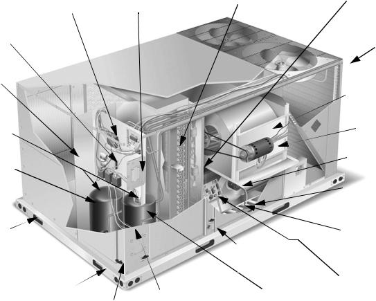
Simplicity® control board w/ screw connector for T-stat wiring and network connections
Terminal block for hi-voltage connection
Second model nameplate inside hinged access panel
Disconnect location |
Filter access (2” throw-away) |
Filter drier (solid core) |
(optional disconnect switch) |
|
|
|
|
|
|
|
Condenser section |
|
|
Slide-out motor and |
|
|
blower assembly fo |
|
|
easy adjustment |
|
|
and service |
Dual stage cooling for maximum comfort
Compressor #2 access (highefficiency compressor w/crankcase heater)
Base rails w/forklift slots (three sides) and lifting holes
Roof curbs in eightand fourteen- |
|
|
inch heights. Roof curbs for transi- |
|
|
tioning from York Sunline™ foot- |
|
Side entry power |
print to the DH Series footprints |
Tool-less door latch |
|
are also available |
and control wiring |
|
(field-installed accessory) |
|
knockouts |
Slide-out drain pan with steel 3/4” NPT, female connection
Compressor #1 access (high-efficiency compressor w/crankcase heater)
Belt-drive  blower motor
Power ventor motor
20-gauge aluminized steel tubular  heat exchanger for long life (stainless
steel option)
Two-stage gas heating to maintain warm, comfortable temperature
Intelligent control board for safe and efficient operation
FIGURE 1 - PREDATOR® MagnaDRY™ DR090, 120
4 |
Unitary Products Group |
246721-YTG-C-0606
|
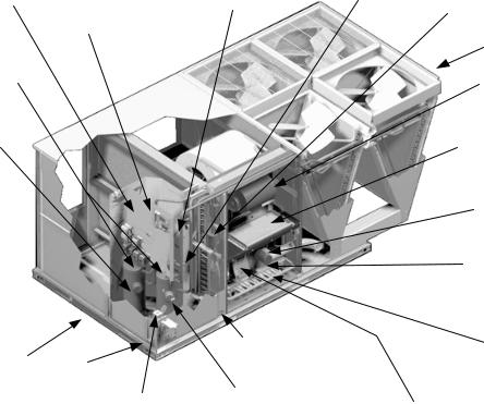
Simplicity™ Control |
Disconnect |
Filter access |
|
|
board w/screw |
|||
Second model |
location (optional |
(2" throw-away) |
||
connectors for T-stat |
||||
disconnect switch) |
|
|||
nameplate inside |
Filter drier (solid core) |
|||
|
||||
wiring and Network |
|
|||
hinged access panel |
|
|
||
Connection |
|
|
||
|
|
|
||
|
|
|
Condenser Section |
|
Dual stage cooling |
|
|
Belt-drive blower |
|
for maximum |
|
|
||
|
|
motor |
||
comfort |
|
|
||
|
|
|
||
|
|
|
Slide out motor |
|
Compressor #2 |
|
|
and blower |
|
|
|
assembly for easy |
||
access |
|
|
||
|
|
adjustment and |
||
(high-efficiency |
|
|
||
|
|
service |
||
compressor w/ |
|
|
||
|
|
|
||
crankcase heater) |
|
|
Power ventor |
|
|
|
|
||
|
|
|
motor |
Base rails w/ forklift slots
(three sides)
and lifting  holes
holes
Roof curbs in eight-and fourteen-inch heights.
Roof curbs for transitioning from York Sunline TM footprint to the DM/DH/DJ Series footprint are available (field-installed accessory)
Tool-less door latch
Side entry power and control wiring knockouts
Slide-out drain pan with brass ¾" NPT, female connection
Compressor #1 access (high-efficiency compressor w/crankcase heater)
20-gauge aluminized steel tubular heat exchanger for long life (stainless steel option)
Two-stage gas heating to maintain warm, comfortable temperature
Intelligent control board for safe and efficient operation
FIGURE 2 - PREDATOR® MagnaDRY™ DR150
FEATURES
•High Efficiency – High efficiency units reach as high as 11.2 EER. Gas/electric units have electronic spark ignition and power vented combustion with steady state efficiencies of 80%. These efficiencies exceed all legislated minimum levels and provide low operating costs.
•Service Friendly – The Predator® incorporates a number of enhancements which improve serviceability.
The motor and blower slide out of the unit as a common assembly. This facilitates greater access to all the indoor airflow components, thus simplifying maintenance and adjustment.
Service time is reduced through the use of hinged, toolless panels. Such panels provide access to frequently inspected components and areas, including the control box, compressors, filters, indoor motor & blower, and the heating section. The panels are screwed in place at the factory to prevent access by children or other unauthorized persons. It is recommended that the panels be secured with screws once service is complete.
Service windows have been placed in both condenser section walls. Rotation of the cover allows easy access to the condenser coils for cleaning or inspection.
Both the unit control board and ignition control board utilize flash codes to aid in diagnosis of unit malfunctions. Unique alarm codes quickly identify the source of the unit alarm.
All units use the same standard filter size. This standardization removes any confusion on which filter sizes are needed for replacement.
The non-corrosive drain pan slides out of the unit to permit easy cleaning. The drain pan is accessed by removing the drain pan cover plate on the rear of the unit. Once the plate is removed, the drain pan slides out through the rear of the unit.
All Predator® units have a second model nameplate located inside the control access door. This is to prevent deterioration of the nameplate through weathering.
•Environmentally Aware – For improved Indoor Air Quality, foil faced insulation is used exclusively throughout the units.
•Balanced Heating – The Predator® offers “Ultimate Heating Comfort” with a balance between 1st and 2nd stage gas heating. The first stage of a gas heat Predator® unit provides 60% of the heating capacity. Balanced heating allows the unit to better maintain desired temperatures.
•Convertible Airflow Design – The side duct openings are covered when they leave the factory. If a side supply/
Unitary Products Group |
5 |
return is desired, the installer simply removes the two side duct covers from the outside of the unit and installs them over the down shot openings. No panel cutting is required. Convertible airflow design allows maximum field flexibility and minimum inventory.
•System Protection - Suction line freezestats are supplied on all units to protect against loss of charge and coil frosting when the economizer operates at low outdoor air temperatures while the compressors are running. Every unit has solid-core liquid line filter-driers and high and lowpressure switches. Internal compressor protection is standard on all compressors. Crankcase heaters are standard on reciprocating compressors. Scroll compressors do not require crankcase heaters. Phase Monitors are standard on units with scroll compressors. This accessory monitors the incoming power to the unit and protects the unit from phase loss and reversed phase rotation.
•Advanced Controls - Simplicity® control boards have standardized a number of features previously available only as options or by utilizing additional controls.
•Low Ambient - An integrated low-ambient control allows all units to operate in the cooling mode down to 0°F outdoor ambient without additional assistance. Optionally, the control board can be programmed to lockout the compressors when the outdoor air temperature is low or when free cooling is available.
•Anti-Short Cycle Protection - To aid compressor life, an anti-short cycle delay is incorporated into the standard controls. Compressor reliability is further ensured by programmable minimum run times. For testing, the anti-short cycle delay can be temporarily overridden with the push of a button.
•Fan Delays - Fan on and fan off delays are fully programmable. Furthermore, the heating and cooling fan delay times are independent of one another. All units are programmed with default values based upon their configuration of cooling and heat.
•Safety Monitoring - The control board monitors the high and low-pressure switches, the freezestats, the gas valve, if applicable, and the temperature limit switch on gas and electric heat units. The unit control board will alarm on ignition failures, compressor lockouts and repeated limit switch trips.
•Nuisance Trip Protection and Strikes - To prevent nuisance trouble calls, the control board uses a “three times, you’re out” philosophy. The high and low-pressure switches and the freezestats must trip three times within two hours before the unit control board will lock out the associated compressor.
•On Board Diagnostics - Each alarm will energize a trouble light on the thermostat, if so equipped, and flash an alarm code on the control board LED. Each high and low-pressure switch alarm as well as each freezestat alarm has its own flash code. The control board saves the five most recent alarms in memory, and these alarms can be reviewed at any time.
246721-YTG-C-0606
Alarms and programmed values are retained through the loss of power.
•Reliable – From the beginning – All units undergo computer automated testing before they leave the factory. Units are tested for refrigerant charge and pressure, unit
amperage, and 100% functionality. For the long term – All Predator® units are painted with a long lasting, powder paint that stands up over the life of the unit. The paint used has been proven by a 1000 hour salt spray test.
•Flexible Placement – All models and configurations share the same cabinet/footprint and thus the same roof curb. You have the flexibility to set one curb and choose the correct tonnage size and heating option after the internal loads have been determined.
To further simplify planning and installation, Predator® cabinets are designed to fit your roof. With the optional roof curb, the unit ductwork is designed to fit around 24” on-center joists or between 48” on-center joists.
The drain pan can be rotated to drain to either the front or the rear of the unit. Additionally, the drain pan can be fitted to drain through the roof curb. As it is sometimes difficult to have a level installation, the drain pan features a generous slope to ensure proper drainage.
•Full Perimeter Base Rails – The permanently attached base rails provide a solid foundation for the entire unit and protect the unit during shipment. The rails offer forklift access from 3 sides, and rigging holes are available so that an overhead crane can be used to place the units on a roof.
•Easy Installation – Gas and electric utility knockouts are supplied in the unit underside as well as the side of the unit. A clearly identified location is provided to mount a field supplied electrical disconnect switch. Utility connections can be made quickly and with a minimum amount of field labor.
All units are shipped with 2” throw-away filters installed.
•Wide Range of Indoor Airflows – All indoor fan motors are belt-drive type providing maximum flexibility to handle most airflow requirements. For high static applications, factory installed alternate indoor fan motors are available. With the optional indoor fan motor, all units can supply nominal airflow at a minimum of 1.5” ESP.
•Warranty - All models include a 1-year limited warranty on the complete unit. Compressors and electric heater elements each carry a 5-year warranty. Aluminized steel and stainless steel tubular heat exchangers carry a 10year warranty.
FACTORY INSTALLED OPTIONS
YORK® offers several equipment options factory installed, for the Predator® line.
•Optional Factory Installed Economizers - Predator units offer a variety of optional factory installed economizers with low leak dampers. The outdoor air enthalpy sensor enables economizer operation if the outdoor enthalpy is less than the setpoint of the economizer logic module. See Table 38 to determine the correct economizer for your application.
6 |
Unitary Products Group |
246721-YTG-C-0606
•Downflow Economizer - (With barometric relief) - The economizer is provided with a single enthalpy input. The economizer is 2% low leakage type, and is shipped installed and wired. The installer needs only to assemble and mount the outdoor air hood (Provided). The economizer has spring return, fully modulating damper actuators and is capable of introducing up to 100% outdoor air. As the outdoor air intake dampers open, the return air dampers close. The changeover from mechanical refrigeration to economizer operation is regulated by the standard single enthalpy input. There is an optional input dual dry bulb available. To meet regulated air standards, the
economizer control accepts an optional CO2 input for demand ventilation. With single enthalpy input, the economizer control monitors outdoor air. The dual enthalpy kit provides a second input used to monitor the return air. With a dual input kit installed, the economizer control compares the values of the two enthalpy or temperature inputs and positions the dampers to provide the maximum efficiency possible.
•Horizontal Economizer - (Without barometric relief) - All features of the downflow economizer exist except you must order the duct mount barometric relief separately. You must order a 1EH0408 if you are installing a power exhaust. You can order a 1RD0411 Barometric Relief for horizontal flow economizers only.
•Slab Economizer for Energy Recovery Ventilators- (With barometric relief and Fresh Air Hood)
- The economizer is provided with a single enthalpy input. The economizer is 2% low leakage type, and is shipped installed and wired. The economizer has spring return, fully modulating damper actuators and is capable of introducing up to 100% outdoor air. As the outdoor air intake dampers open, the return air dampers close. The changeover from mechanical refrigeration to economizer operation is regulated by the standard single enthalpy input. There is an optional input dual dry bulb available. To meet regulated air standards, the economizer control accepts
an optional CO2 input for demand ventilation.With
single enthalpy input, the economizer control monitors outdoor air. The dual enthalpy kit provides a second input used to monitor the return air. With a dual input kit installed, the economizer control compares the values of the two enthalpy or temperature inputs and positions the dampers to provide the maximum efficiency possible.
•Power Exhaust (Downflow only) - This accessory installs in the unit with a down flow economizer.
•Motorized Outdoor Air Damper - The motorized outdoor air damper includes a slide-in/plug-in damper assembly with an outdoor air hood and filters. The outdoor air dampers open to the preset position when the indoor fan motor is energized. The damper has a range of 0% to 100% outdoor air entry. Factory installed option or field installed accessory.
•Alternate Indoor Blower Motor - For applications with high static restrictions, units are offered with optional indoor motors that provide higher static output and/or higher airflow, depending upon the installer’s needs.
•Aluminized Steel Gas Heat Exchanger - For applications in non-corrosive environments.
•Stainless Steel Gas Heat Exchanger - For applications in corrosive environments, this option provides a full stainless steel heat exchanger assembly.
•Stainless Steel Drain Pan - Provides years of trouble free operation in corrosive environments.
•Electric Heaters - The electric heaters range from 9kW to 54kW and are available in all the voltage options of the base units. All heaters are dual staged. All heaters are intended for single point power supply.
•Disconnect Switch - For gas heat units and cooling units with electric heat, a HACR breaker sized to the unit is provided. For cooling only units, a switch sized to the largest electric heat available for the particular unit is provided. Factory installed option only.
•Convenience Outlet - (Non-Powered/Powered) - This option locates a 120V single-phase GFCI outlet with cover, on the corner of the unit housing adjacent to the compressors. The “Non-powered” option requires the installer to provide the 120V single-phase power source and wiring. The “Powered” option is powered by a stepdown transformer in the unit. Factory installed option only.
•Smoke Detectors - The smoke detectors stop operation of the unit by interrupting power to the control board if smoke is detected within the air compartment. Available for both the supply and/or return air.
Factory installed smoke detectors in the return air, may be subjected to freezing temperatures during "off" times due to out side air infiltration. These smoke detectors have an operational limit of 32 °F to 131°F. Smoke detectors installed in areas that could be out side those limitations will have to be moved to prevent having false alarms.
•Phase Monitors - Designed to prevent unit damage. The phase monitor will shut the unit down in an out-of phase condition. (Standard on units with Scroll Compressors.)
•Coil Guard - Customers can purchase a coil guard kit to protect the condenser coil from damage. Additionally, this kit stops animals and foreign objects from entering the space between the inner condenser coil and the main cabinet. This is not a hail guard kit.
•Dirty Filter Switch - This kit includes a differential pressure switch that energizes the fault light on the unit thermostat, indicating that there is an abnormally high pressure drop across the filters. Factory installed option or field installed accessory.
Unitary Products Group |
7 |
•Technicoat Condenser Coils - The condenser coils are coated with a phenolic coating for protection against corrosion due to harsh environments.
•Technicoat Evaporator Coil - The evaporator coils are coated with a phenolic coating for protection against corrosion due to harsh environments.
•BAS - Building Automation System Controls Simplicity® Intelli-Comfort™ Control - The York
Simplicity® Intelli-Comfort™ control is factory installed. It includes a supply air sensor, a return air sensor, and an outside air sensor. There are provisions for a field installed dirty filter indicator switch, an air-proving switch, an Outside Air Humidity sensor, a Return Air Humidity sensor, an Inside IAQ sensor, and an Outside Air IAQ sensor. Construction mode operation, 365-day real time clock with 7 day programming plus holiday scheduling is built-in. Two different modes of demand ventilation are
achieved through the Intelli-Comfort™ using CO2 sensors. It uses an inside CO2 sensor to perform Demand Ventilation. It can also use an Outside CO2 sensor to perform Differential Demand Ventilation. It uses a Patented Comfort Ventilation algorithm to provide comfortable ventilation air temperature. The patented economizer-loading algorithm will protect the equipment when harsh operating conditions exist. Humidity in the occupied space or return duct can be monitored and controlled via humidity sensors and the on-board connection for hot gas re-heat system. It uses the Intelli-Start algorithm to maximize energy savings by recovering the building from the Unoccupied Setpoints to the Occupied Setpoints just in time for the Occupied Time Period to begin. The Simplicity® Intelli-Comfort™ balances space temperature, ventilation air temperature, CO2 and humidity for ultimate comfort.
•Simplicity® Intelli-Comfort™ with ModLINC Control - The York Simplicity® Intelli-Comfort™ with ModLINC control is factory installed. It includes all the features of the Intelli-Comfort™ control with an additional control to translate communications from MODBUS to the BACnet MSTP protocol.
•Novar® BAS Control - The Novar® ETC-3 building automation system controller is factory installed. Incudes supply air sensor, return air sensor, dirty filter indicator switch, and air proving switch.
•Johnson Controls BAS Control - The Johnson Control YK-UNT-1126 building automation system controller is factory installed. Includes supply air sensor, return air sensor, dirty filter indicator switch, and air proving switch.
•CPC BAS Control - The Computer Process Controls Model 810-3060 ARTC Advanced Rooftop building automation system controller is factory installed. Includes supply air sensor, return air sensor, dirty filter indicator switch and air proving switch.
•Honeywell BAS Control - The Honeywell W7750C building automation system controller is factory installed.
246721-YTG-C-0606
Includes air supply sensor, return air sensor, dirty filter indicator switch, and air proving switch.
FIELD INSTALLED ACCESSORIES
YORK® offers several equipment accessories for field installation, for the Predator® line.
•Downflow Economizer - (With barometric relief) - The economizer is provided with a single enthalpy input. The economizer is 2% low leakage type. The economizer has spring return, fully modulating damper actuators and is capable of introducing up to 100% outdoor air. As the outdoor air intake dampers open, the return air dampers close. The changeover from mechanical refrigeration to economizer operation is regulated by the standard single enthalpy input. There is an optional input dual dry bulb available. To meet regulated air standards, the economizer
control accepts an optional CO2 input for demand ventilation. With single enthalpy input, the economizer control monitors outdoor air. The dual enthalpy kit provides a second input used to monitor the return air. With a dual input kit installed, the economizer control compares the values of the two enthalpy or temperature inputs and positions the dampers to provide the maximum efficiency possible.
•Horizontal Economizer - (Without barometric relief) - All features of the downflow economizer exist except you must order the duct mount barometric relief separately.
You must order a 1EH0408 if you are installing a power exhaust. You can order a 1RD0411 Barometric Relief for horizontal flow economizer.
•Slab Economizer for Energy Recovery Ventilator- (Without barometric relief or Fresh Air Hood) - The economizer is provided with a single enthalpy input. The economizer is 2% low leakage type. The economizer has spring return, fully modulating damper actuators and is capable of introducing up to 100% outdoor air. As the outdoor air intake dampers open, the return air dampers close. The changeover from mechanical refrigeration to economizer operation is regulated by the standard single enthalpy input. There is an optional input dual dry bulb available. To meet regulated air standards, the economizer
control accepts an optional CO2 input for demand ventilation.With single enthalpy input, the economizer control monitors outdoor air. The dual enthalpy kit provides a second input used to monitor the return air. With a dual input kit installed, the economizer control compares the values of the two enthalpy or temperature inputs and positions the dampers to provide the maximum efficiency possible.
You can order 1EH0409 Barometric Relief/FA Hood for field installations without an ERV.
•Dual Enthalpy Control, Accessory - This kit contains the required components to convert a single enthalpy economizer to dual enthalpy.
•Barometric Relief Damper - Zero to 100% capacity barometric relief dampers for use with horizontal flow, or field installed slab economizers.
8 |
Unitary Products Group |
246721-YTG-C-0606
•Power Exhaust - This accessory installs in the unit with a down flow economizer. Power exhaust plugs into the connector in the unit bulkhead. You must purchase
1EH0408 barometric relief when applying to a horizontal flow application.
•Manual Outdoor Air Damper - Like the motorized outdoor air damper, each manual outdoor air damper includes a slide-in damper assembly with an outdoor air hood and filters. Customers have a choice of dampers with ranges of 0% to 100% or 0% to 35% outdoor air entry.
•Motorized Outdoor Air Damper - The motorized outdoor air damper includes a slide-in/plug-in damper assembly with an outdoor air hood and filters. The outdoor air dampers open to the preset position when the indoor fan motor is energized. The damper has a range of 0% to 100% outdoor air entry. Factory installed option or field installed accessory.
•Smoke Detectors - The smoke detectors stop operation of the unit by interrupting power to the control board if smoke is detected within the air compartment.
•CO2 Sensor - Senses CO2 levels and automatically overrides the economizer when levels rise above the preset limits.
•Dirty Filter Switch - This kit includes a differential pressure switch that energizes the fault light on the unit thermostat, indicating that there is an abnormally high pressure drop across the filters.
•Coil Guard - Field installed decorative wire coil guard.
•Hail Guard - This kit includes a sloped hood which installs over the outside condenser coil and prevents damage to the coil fins from hail strikes. Field installed accessory only.
•Flue Exhaust Extension Kit - In locations with wind or weather conditions which may interfere with proper exhausting of furnace combustion products, this kit can be installed to prevent the flue exhaust from entering nearby fresh air intakes.
•-60°F Gas Heat Kit - For installations which require gas heat units to perform in low ambient temperatures, a gas section heating kit is available. This kit provides electric heat in the gas heat controls section to ensure the gas valve and controls will continue to function properly at extremely low temperatures.
•Gas Heat High Altitude Kit - This kit converts a gas heat unit to operate at high altitudes, 2,000 to 6,000 feet. Conversion kits are available for natural gas and propane.
•Gas Heat Propane Conversion Kit - This kit converts a gas-fired heater from natural gas to propane. It contains the main burner orifices and gas valve replacement springs.
•Gas Piping Kit - Contains pipe nipples, fittings and gas cock required for gas supply connection with external shut off.
•Electric Heaters - The electric heaters range from 9 kW to 54kW and are available in all the voltage options of the base units. All heaters are dual staged. Cooling units include an adapter panel for easy installation of the electric heaters. Necessary hardware and connectors are
included with the heaters. All heaters are intended for single point power supply.
•Low Limit / Compressor Lockout Kit
1.Compressor Lockout (CLO): To prevent mechanical (compressorized) operation of the unit during cold outdoor conditions where there is a risk of returning liquid refrigerant back to the compressors.
2.Low Limit Control (LLC): To prevent the supply air from dropping below a specified setpoint by utilizing the units first stage heating means when there is a demand for cooling during cold outside conditions.
•Metal Frame Filter Kit - Metal frame with polyester filter medium.
•Permanent Filters - Permanent filters are available.
•Roof Curbs - The roof curbs have insulated decks and are shipped disassembled The roof curbs are available in 8” and 14” heights. For applications with security concerns, burglar bars are available for the duct openings of the roof curbs.
•Roof Curb Transition - Single Piece Adapter (10” High) -
Roof curbs for transitioning from Sunline™ units to Predator® units. Fits 7.5 to 12.5 Sunline™ roof curbs only.
•Burglar Bars - Mount in the supply and return openings to prevent entry into the duct work.
•Thermostat - The units are designed to operate with 24volt electronic and electro-mechanical thermostats. All units (with or without an economizer) operate with twostage heat/two-stage cool or two-stage cooling only thermostats, depending upon unit configuration.
REHEAT MODE SEQUENCE OF OPERATION
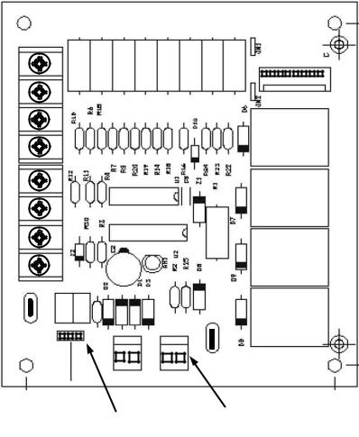
The reheat control board allows the user to select two different modes of operation via a jumper connection on the board. (See Figure 3.) Each mode is described below. Refer to Figures 3 - 5 when reading this section.
“NORMAL” MODE
When the reheat control board (RCB) detects a need for dehumidification (24VAC) at "HUM" via the field supplied dehumidistat connected to RHTB-1 and RHTB-2 and there is not a call for cooling, it energizes the hot gas relay (HGR), which energizes the 3-way valve (SOL 3), the condenser coil valve (SOL 2), and de-energizes the reheat coil bleed valve (SOL 1). (In the DR150, SOL 2 is only energized when the discharge pressure in circuit #1 rises above 235 psig and deenergizes SOL 2 after the discharge pressure falls below 175 psig. Both outdoor fans of circuit #1 in the DR150 also disengage to conserve energy.) The Y1 signal is passed to the unit control board (UCB), which engages circuit # 1, resulting in circuit #1 reheat mode operation.
When the room thermostat calls for first stage cooling, with or without a call for dehumidification, the RCB senses a signal through "Y1", de-energizing the HGR, which de-energizes SOL 3 and SOL 2 and energizes SOL 1, engaging circuit #1, resulting in circuit #1 cooling mode operation.
Unitary Products Group |
9 |
When the room thermostat calls for second stage cooling, the RCB senses a signal through "Y1" & "Y2" and engages circuit #1 and circuit #2 in cooling mode.
Indoor blower operation is initiated upon a call for first stage cooling, second stage cooling or dehumidification.
Anytime there is a call for 2 stages of cooling, the unit will not operate in the reheat mode, even if there is a call for dehumidification at "HUM".
The unit will not operate in the reheat mode if there is any call for heating.
On units with economizers, the unit will not operate in the reheat mode if there is a call for cooling and the economizer is operating as first stage of cooling.
All safety devices function as previously described.
246721-YTG-C-0606
falls below 175 psig. Both outdoor fans of circuit #1 in the DR150 also disengage to conserve energy.) The unit then operates with circuit #1 in reheat mode and circuit #2 in cooling mode.
When the room thermostat calls for first stage cooling while there is still a call for dehumidification, no operational change is made. The call for cooling is ignored and the unit continues to operate with circuit #1 in reheat mode and circuit #2 in cooling mode.
When the room thermostat calls for second stage cooling, the RCB senses a signal through "Y1" and "Y2" and de-ener- gizes the HGR, which de-energizes SOL 3 and SOL 2, and energizes SOL 1. Both circuits operate in the cooling mode.
Indoor blower operation is initiated upon a call for first stage cooling, second stage cooling or dehumidification.
"ALTERNATE” MODE
When the RCB detects a need for dehumidification (24VAC) at "HUM" via the field supplied dehumidistat connected to RHTB-1 and RHTB-2, and there is not a call for cooling, it energizes the HGR, which energizes the SOL 3, SOL 2, and de-energizes SOL 1. (In the DR150, SOL 2 is only energized when the discharge pressure in circuit #1 rises above 235 psig and de-energizes SOL 2 after the discharge pressure
Anytime there is a call for 2 stages of cooling, the unit will not operate in the reheat mode, even if there is still a call for dehumidification at "HUM".
The unit will not operate in the reheat mode if there is any call for heating.
All safety devices function as previously described.
R
Y1
P4
Y2
K1
G
W1
K2
W2
OCC
K4
C
K3
COM
` |
P6 |
|
|
P5 |
P3 |
|
|
|
|
|
|
|
|
HGRR |
|
HGR |
|||||||
|
HUM |
|||||||
|
MODE |
|
|
|
DEHUMIDISTAT |
|||
SELECTION |
|
|
|
HARNESS |
||||
|
JUMPER |
|
|
|
CONNECTION |
|||
FIGURE 3 - REHEAT CONTROL BOARD
10 |
Unitary Products Group |
246721-YTG-C-0606


|
|
|
|
|
|
|
|
|
|
|
|
|
|
||
|
|||
|
|||
|
|
||
|
|
||
|
|
||
|
|
||
|
|
|
|
|
|
|
|
|
|
|
FIGURE 4 - DR090 & 120 REHEAT CONTROLS
Unitary Products Group |
11 |

246721-YTG-C-0606
|
|
|
|
|
|
|
|


FIGURE 5 - DR150 REHEAT CONTROLS
12 |
Unitary Products Group |
246721-YTG-C-0606
TABLE 1: ACCESSORIES
Part Number |
Description |
Weight |
1RC0470 |
Roof Curb, 8" Height |
- |
1RC0471 |
Roof Curb, 14" Height |
- |
1RC0472 |
Roof Curb, Transition (7.5 T through 12.5 T) |
- |
1BD0408 |
Burglar Bars, Downflow |
- |
2TP04520925 |
Electric Heat 9kW 230V |
- |
2TP04521825 |
Electric Heat 18kW 230V |
- |
2TP04522425 |
Electric Heat 24kW 230V |
- |
2TP04523625 |
Electric Heat 36kW 230V |
- |
2TP04525425 |
Electric Heat 54kW 230V |
- |
2TP04520946 |
Electric Heat 9kW 460V |
- |
2TP04521846 |
Electric Heat 18kW 460V |
- |
2TP04522446 |
Electric Heat 24kW 460V |
- |
2TP04523646 |
Electric Heat 36kW 460V |
- |
2TP04525446 |
Electric Heat 54kW 460V |
- |
2TP04520958 |
Electric Heat 9kW 575V |
- |
2TP04521858 |
Electric Heat 18kW 575V |
- |
2TP04522458 |
Electric Heat 24kW 575V |
- |
2TP04523658 |
Electric Heat 36kW 575V |
- |
2TP04525458 |
Electric Heat 54kW 575V |
- |
1FA0411 |
Manual Outside Air Damper 0-35%, Downflow (Incl. Hood, Damper & Filters, No Barometric Relief) |
- |
1FA0412 |
Manual Outside Air Damper 0-100%, Downflow (Incl. Hood, Damper & Filters, No Barometric Relief) |
- |
2MD04702724 |
Motorized Damper, Downflow (Incl. Hood, Damper & Filter, no Barometric Relief) |
- |
2MD04703324 |
Motorized Damper, Horizontal (Incl. Hood, Damper & Filter, no Barometric Relief) |
|
2EE04705024 |
Economizer, Downflow (Incl. Barometric Relief & All Hoods) |
124 lbs. |
2EE04705124 |
Economizer, Horizontal (Incl. Dampers & Hoods, no Barometric Relief) |
97 lbs. |
2EE04705224 |
Economizer, Slab, Downflow (Incl. Dampers only no Hoods or Barometric Relief) |
|
2PE04703225 |
Power Exhaust, Downflow, 230V (For Units with Economizer only) |
- |
2PE04703246 |
Power Exhaust, Downflow, 460V(For Units with Economizer only) |
- |
2PE04703258 |
Power Exhaust, Downflow, 580V (For Units with Economizer only) |
- |
2EC04700924 |
Dual Enthalpy Control (Use with Single Enthalpy Economizer) |
- |
1EH0407 |
Hood Kit, Downflow Economizer (Included with all Downflow Economizers) |
|
1RD0411 |
Barometric Relief Kit, Ductmount for Horizontal Application (Incl. Damper & Hood) |
|
1EH0408 |
Barometric Relief Kit, Ductmount for Horizontal Application w/Power Exhaust (Incl. Damper & Hood) |
25 lbs. |
1EH0409 |
Barometric Relief / Hood Kit, for Field Installed Slab Econ. w/o ERV (Incl. Barometric Relief & FA Hood) |
- |
2AQ04700424 |
CO2 Detector Unit Mount |
- |
2AQ04700324 |
CO2 Detector Space Mount |
- |
2SD04700424 |
Smoke Detector, Supply or Return (Return Not Available with Horizontal Economizer) |
- |
2MK04700624 |
Low Limit / Compressor Lockout Kit |
|
1CG0419 |
Coil Guard (Electric / Electric & HP models): DR090 & 120 |
- |
1CG0420 |
Coil Guard (Gas / Electric models): DR090 & 120 |
- |
1CG0424 |
Coil Guard (Electric / Electric & HP models): DR150 |
|
1CG0425 |
Coil Guard (Gas / Electric models): DR150 |
|
1HG0411 |
Hail Guard Kit |
- |
1GP0404 |
Gas Piping Kit |
- |
1NP0441 |
Propane Conversion Kit |
- |
1HA0442 |
High Altitude Kit for Natural Gas |
- |
1HA0443 |
High Altitude Kit for Propane |
- |
1FE0411 |
Flue Exhaust Extension Kit |
- |
2BC04700106 |
Gas Heat Kit, -60 deg F, 230V |
- |
2BC04700151 |
Gas Heat Kit, -60 deg F, 460V |
- |
2BC04700154 |
Gas Heat Kit, -60 deg F, 575V |
- |
1FL0402 |
Permanent Filter Kit |
- |
2DF0401 |
Dirty Filter Switch |
- |
1FF0410 |
Filter Frame Kit, Metal |
- |
Unitary Products Group |
13 |
246721-YTG-C-0606
NOMENCLATURE
7.5-12.5 Ton York® Model Number Nomenclature
D R 090 N10 A 2 A AA 3 0 1 2 4 A
Product Category
D = A/C, Single Pkg., R-22
Product Identifier
R = REHEAT
Nominal Cooling Capacity
090 = 7.5 Ton
120 = 10.0 Ton
150 = 12.5 Ton
Heat Type and Nominal Heat Capacity
C00 = Cooling Only. No heat installed
Gas Heat Options
N10 = 100 MBH Output Aluminized Steel
N15 = 150 MBH Output Aluminized Steel
N20 = 200 MBH Output Aluminized Steel
S10 = 100 MBH Output Stainless Steel
S15 = 150 MBH Output Stainless Steel
S20 = 200 MBH Output Stainless Steel
Electric Heat Options
E09 = 9 KW
E18 = 18 KW
E24 = 24 KW
E36 = 36 KW
E54 = 54 KW
Airflow
A = Std. Motor
B = Std. Motor/Econo./Barometric Relief (Downflow
Only)
C = Std. Motor/Econo./Power Exhaust (Downflow Only)
D = Std. Motor/Motorized Damper (Downflow Only)
E = Std. Motor/Horizontal Economizer (No Baro.)
F = Std. Motor/Slab Econo./Power Exhaust
(Downflow Only)
G = Std. Motor/Slab Econo./Barometric Relief
(Downflow Only)
N = Hi Static Mtr.
P = Hi Static Mtr./Econo./Barometric Relief
(Downflow Only)
Q = Hi Static Mtr./Econo./Power Exhaust
(Downflow Only)
R = Hi Static Mtr./Motorized Damper (Downflow Only)
S = Hi Static Mtr./Horizontal Economizer (No Baro.)
T = Hi Static Mtr./Slab Econo./Power Exhaust
(Downflow Only)
U = Hi Static Mtr./Slab Econo./Barometric Relief
(Downflow only)
Voltage
2 = 208/230-3-60
4 = 460-3-60
5 = 575-3-60
Product Style
A = Style A
B = Style B
C = Style C
Configuration Options (not required for all units)
These four digits will not be assigned until a quote is requested, or an order placed.
SS Drain Pan
CPC Controller, DFS, APS
Johnson Controller, DFS, APS
Honeywell Controller, DFS, APS
Novar Controller, DFS, APS
Simplicity IntelliComfort Controller
Simplicity IntelliComfort Controller w/ModLinc
2" Pleated filters
BAS Ready Unit with Belimo Economizer
Shipping Bag
Any Combination of Additional Options that Don’t Have an Option Code Pre-assigned
|
|
Product Generation |
|
|
|
|
|
|
3 |
= Third Generation |
|
|
4 |
= Fourth Generation |
|
|
|
|
|
|
|
|
|
|
|
|
Additional Options |
AA = None |
RC = Coil Guard, Shipping Bag & American Flag |
AB = Phase Monitor |
TA = Technicoat Condenser Coil |
AC = Coil Guard |
TJ = Technicoat Evaporator Coil |
AD = Dirty Filter Switch |
TS = Technicoat Evaporator & Condenser Coils |
AE = Phase Monitor & Coil Guard |
|
AF = Phase Monitor & Dirty Filter Switch |
|
AG = Coil Guard & Dirty Filter Switch |
|
AH = Phase Monitor, Coil Guard & Dirty Filter Switch |
|
|
|
ZZ= If desired option combination is not listed above, ZZ will be assigned and configuration options will be located in digits 15-18.
Installation Options
A = No Options Installed
B = Option 1
C = Option 2
D = Options 1 & 2
E = Option 3
F = Option 4
G = Options 1 & 3
H = Options 1 & 4
J = Options 1, 2 & 3
K = Options 1, 2, & 4
L = Options 1,3 & 4
M = Options 1, 2, 3, & 4
N = Options 2 & 3
P = Options 2 & 4
Q = Options 2, 3, & 4
R = Options 3 & 4
S = Option 5
T = Options 1 & 5
U = Options 1, 3, & 5
V = Options 1, 4, & 5
W = Options 1, 3, 4, & 5
X = Options 3 & 5
Y = Options 4 & 5
Z = Options 3, 4 & 5
Options
1 = Disconnect
2 = Non-Pwr'd Conv. Outlet
3 = Smoke Detector S.A.
4 = Smoke Detector R.A.
5 = Pwr'd Conv. Outlet
14 |
Unitary Products Group |
246721-YTG-C-0606
TABLE 2: PHYSICAL DATA
|
Component |
|
Models |
|
|
|
|
|
|
||
|
90 |
120 |
150 |
||
|
|
||||
|
|
|
|
|
|
Evaporator |
Blower, Centrifugal (Dia. X Wd. In.) |
15 x 15 |
15 x 15 |
15 x 15 |
|
Motor, Standard (HP) |
1-1/2 |
2 |
3 |
||
Blower |
|||||
Motor, Optional (HP) |
2 |
3 |
5 |
||
|
|||||
|
Rows |
3 |
4 |
4 |
|
Evaporator Coil |
Fins per Inch |
15 |
15 |
15 |
|
Height (in.) |
32 |
40 |
40 |
||
|
|||||
|
Face Area (ft.2) |
10.6 |
13.2 |
13.2 |
|
|
Rows |
2 |
2 |
2 |
|
Reheat Coil |
Fins per Inch |
13 |
13 |
13 |
|
Height (in.) |
28 |
36 |
36 |
||
|
|||||
|
Face Area (ft.2) |
7.8 |
10 |
10 |
|
|
Quantity |
2 |
2 |
4 |
|
Condenser Fan |
Propeller Dia. (in., each) |
24 |
24 |
24 |
|
Motor (HP, each) |
1/3 |
3/4 |
1/3 |
||
|
|||||
|
CFM, Nominal (each) |
3400 |
4400 |
3500 |
|
|
Number of Coils |
2 |
2 |
4 |
|
|
Rows (each) |
1 |
2 |
2 |
|
Condenser Coil |
Fins per Inch |
20 |
20 |
15 |
|
|
Height (in., each) |
44 |
44 |
36 |
|
|
Face Area (ft.2 each) |
14.5 |
14.5 |
11.9 |
|
Refrigerant |
System 1 (lb./oz.) |
8/0 |
12/12 |
22/8 |
|
Charge |
System 2 (lb./oz.) |
6/6 |
10/2 |
21/4 |
|
Compressors |
Quantity |
2 |
2 |
2 |
|
Type |
Recip. |
Recip. |
Scroll |
||
|
|||||
Air Filters |
Size (Wd. X Ht. X Thickness in.) |
25 x 20 x 2 |
25 x 20 x 2 |
25 x 20 x 2 |
|
Quantity |
4 |
4 |
4 |
||
|
Unitary Products Group |
15 |
|
|
|
|
|
|
|
|
|
|
|
|
246721-YTG-C-0606 |
|
TABLE 3: DR CAPACITY RATINGS |
|
|
|
|
|
|
|
|
|||||
|
|
|
|
|
|
|
|
|
|
|
|
|
|
|
|
Cooling Capacity |
|
|
|
Nominal |
|
Gas Heat Capacity |
|
Gas |
|||
|
|
ARI Ratings1 |
|
|
Sound |
|
|
||||||
|
|
|
|
Electric |
|
|
|||||||
|
|
|
|
|
|
|
|
||||||
Size |
Model |
|
|
|
|
CFM |
Rating |
Heat |
|
|
|
|
Line |
|
|
|
|
Input |
Output |
Seasonal |
Temp. |
Size |
|||||
|
|
|
|
|
|
|
(dB)2 |
Capacity3 |
|||||
|
|
MBH |
EER |
IPLV |
|
|
Efficiency |
Rise |
(in. OD) |
||||
|
|
|
|
|
(kW) |
(MBH) |
(MBH) |
||||||
|
|
|
|
|
|
|
|
(%) |
(°F) |
|
|||
|
|
|
|
|
|
|
|
|
|
|
|
||
|
|
|
|
|
|
|
|
|
|
|
|
|
|
|
|
|
|
|
|
|
|
|
|
|
|
|
|
|
Cooling |
|
|
|
|
|
|
- |
- |
- |
- |
- |
- |
|
Only |
|
|
|
|
|
|
||||||
|
|
|
|
|
|
|
|
|
|
|
|
|
|
|
|
|
|
|
|
|
|
|
|
|
|
|
|
090 |
Electric |
90 |
11.2 |
11.65 |
|
3000 |
84 |
9, 18, 24, |
- |
- |
- |
- |
- |
Heat |
|
36 |
|||||||||||
|
|
|
|
|
|
|
|
|
|
|
|
|
|
|
Gas Heat |
|
|
|
|
|
|
- |
120 |
96 |
80 |
15-45 |
3/4 |
|
|
|
|
|
|
|
|
|
|
|
|
|
|
|
Gas Heat |
|
|
|
|
|
|
- |
180 |
144 |
80 |
30-60 |
3/4 |
|
|
|
|
|
|
|
|
|
|
|
|
|
|
|
Cooling |
|
|
|
|
|
|
- |
- |
- |
- |
- |
- |
|
Only |
|
|
|
|
|
|
||||||
|
|
|
|
|
|
|
|
|
|
|
|
|
|
|
|
|
|
|
|
|
|
|
|
|
|
|
|
120 |
Electric |
116 |
11.2 |
11.40 |
|
3480 |
90 |
18, 24, 36, |
- |
- |
- |
- |
- |
Heat |
|
54 |
|||||||||||
|
|
|
|
|
|
|
|
|
|
|
|
|
|
|
Gas Heat |
|
|
|
|
|
|
- |
180 |
144 |
80 |
20-50 |
3/4 |
|
|
|
|
|
|
|
|
|
|
|
|
|
|
|
Gas Heat |
|
|
|
|
|
|
- |
240 |
192 |
80 |
35-65 |
3/4 |
|
|
|
|
|
|
|
|
|
|
|
|
|
|
|
Cooling |
|
|
|
|
|
|
- |
- |
- |
- |
- |
- |
|
Only |
|
|
|
|
|
|
||||||
|
|
|
|
|
|
|
|
|
|
|
|
|
|
|
|
|
|
|
|
|
|
|
|
|
|
|
|
150 |
Electric |
148 |
11.1 |
11.7 |
|
3750 |
86 |
18, 24, 36, |
- |
- |
- |
- |
- |
Heat |
|
54 |
|||||||||||
|
|
|
|
|
|
|
|
|
|
|
|
|
|
|
Gas Heat |
|
|
|
|
|
|
- |
180 |
144 |
80 |
10-40 |
3/4 |
|
|
|
|
|
|
|
|
|
|
|
|
|
|
|
Gas Heat |
|
|
|
|
|
|
- |
240 |
192 |
80 |
25-55 |
3/4 |
|
|
|
|
|
|
|
|
|
|
|
|
|
|
1.Rated at 95°F ambient 80°F dry bulb and 67°F wet bulb.
2.Rated in accordance with ARI 270 standard.
3.See Table 15.
TABLE 4: UNIT VOLTAGE LIMITATIONS
POWER RATING |
MIN. |
MAX. |
208/230-3-60 |
187 |
252 |
460-3-60 |
432 |
504 |
|
|
|
575-3-60 |
540 |
630 |
16 |
Unitary Products Group |
246721-YTG-C-0606
TABLE 5: COOLING CAPACITY DR090 UNIT
Air On |
|
Temperature of Air on Condenser Coil 85°F |
|
|
|
Temperature of Air on Condenser Coil 95°F |
|
||||||||||||||||||
Evap. Coil |
|
|
|
|
|
||||||||||||||||||||
|
|
|
|
|
|
|
|
|
|
|
|
|
|
|
|
|
|
|
|
|
|
|
|
||
|
|
|
|
|
|
|
|
|
|
|
|
|
|
|
|
|
|
|
|
|
|
|
|
||
|
|
Total |
Tot. |
|
|
Sensible Capacity (MBH) |
|
|
Total |
Tot. |
|
|
|
Sensible Capacity (MBH) |
|
||||||||||
CFM |
WB (°F) |
Cap.* |
Input† |
|
|
|
|
|
|
|
|
|
Cap.* |
Input† |
|
|
|
|
|
|
|
|
|
||
|
|
|
Return Dry Bulb (°F) |
|
|
|
|
|
Return Dry Bulb (°F) |
|
|
|
|||||||||||||
|
|
(MBH) |
(kW) |
86 |
83 |
|
80 |
77 |
74 |
|
71 |
68 |
(MBH) |
(kW) |
|
86 |
83 |
|
80 |
77 |
|
74 |
|
71 |
68 |
|
|
|
|
|
|
|
|
|
|
|
|
|
|
|
|
|
|
|
|
|
|
|
|
|
|
|
72 |
105 |
6.7 |
60 |
54 |
|
47 |
41 |
35 |
|
28 |
22 |
96 |
7.3 |
|
57 |
50 |
|
44 |
38 |
|
31 |
|
25 |
18 |
2250 |
67 |
94 |
6.5 |
73 |
67 |
|
61 |
54 |
48 |
|
41 |
35 |
87 |
7.1 |
|
70 |
64 |
|
57 |
51 |
|
45 |
|
38 |
32 |
62 |
85 |
6.3 |
85 |
79 |
|
72 |
66 |
60 |
|
53 |
47 |
78 |
6.9 |
|
78 |
74 |
|
68 |
62 |
|
55 |
|
49 |
42 |
|
|
|
|
|
|
|
|
|||||||||||||||||||
|
57 |
82 |
6.3 |
82 |
82 |
|
75 |
69 |
62 |
|
56 |
50 |
78 |
6.9 |
|
78 |
76 |
|
70 |
63 |
|
57 |
|
50 |
44 |
|
|
|
|
|
|
|
|
|
|
|
|
|
|
|
|
|
|
|
|
|
|
|
|
|
|
|
72 |
109 |
6.8 |
67 |
59 |
|
51 |
44 |
36 |
|
29 |
21 |
100 |
7.4 |
|
63 |
56 |
|
48 |
40 |
|
33 |
|
25 |
18 |
2625 |
67 |
97 |
6.6 |
81 |
73 |
|
66 |
58 |
50 |
|
43 |
35 |
90 |
7.2 |
|
78 |
70 |
|
63 |
55 |
|
48 |
|
40 |
32 |
62 |
88 |
6.4 |
88 |
85 |
|
78 |
71 |
63 |
|
56 |
48 |
81 |
7.0 |
|
81 |
79 |
|
74 |
67 |
|
59 |
|
51 |
44 |
|
|
|
|
|
|
|
|
|||||||||||||||||||
|
57 |
85 |
6.4 |
85 |
85 |
|
82 |
74 |
66 |
|
59 |
51 |
81 |
7.0 |
|
81 |
80 |
|
76 |
68 |
|
61 |
|
53 |
46 |
|
72 |
113 |
6.9 |
73 |
64 |
|
55 |
47 |
38 |
|
29 |
20 |
104 |
7.5 |
|
70 |
61 |
|
52 |
43 |
|
35 |
|
26 |
17 |
3000 |
67 |
101 |
6.8 |
88 |
79 |
|
71 |
62 |
53 |
|
44 |
36 |
93 |
7.3 |
|
85 |
77 |
|
68 |
59 |
|
50 |
|
42 |
33 |
62 |
90 |
6.6 |
90 |
90 |
|
84 |
76 |
67 |
|
58 |
49 |
84 |
7.1 |
|
84 |
84 |
|
80 |
72 |
|
63 |
|
54 |
45 |
|
|
|
|
|
|
|
|
|||||||||||||||||||
|
57 |
88 |
6.6 |
88 |
88 |
|
88 |
79 |
70 |
|
62 |
53 |
84 |
7.0 |
|
84 |
84 |
|
82 |
74 |
|
65 |
|
56 |
47 |
|
72 |
115 |
7.0 |
79 |
69 |
|
59 |
49 |
39 |
|
29 |
19 |
105 |
7.5 |
|
75 |
65 |
|
55 |
45 |
|
35 |
|
25 |
15 |
3375 |
67 |
103 |
6.8 |
95 |
85 |
|
75 |
65 |
55 |
|
45 |
35 |
94 |
7.3 |
|
90 |
82 |
|
72 |
62 |
|
52 |
|
42 |
32 |
62 |
92 |
6.6 |
92 |
92 |
|
89 |
79 |
70 |
|
60 |
50 |
85 |
7.1 |
|
85 |
85 |
|
83 |
73 |
|
63 |
|
54 |
44 |
|
|
|
|
|
|
|
|
|||||||||||||||||||
|
57 |
90 |
6.6 |
90 |
90 |
|
90 |
80 |
70 |
|
60 |
50 |
85 |
7.1 |
|
85 |
85 |
|
84 |
74 |
|
64 |
|
54 |
44 |
|
72 |
118 |
7.0 |
85 |
74 |
|
62 |
51 |
40 |
|
29 |
18 |
106 |
7.6 |
|
80 |
69 |
|
58 |
47 |
|
36 |
|
25 |
13 |
3750 |
67 |
105 |
6.8 |
102 |
91 |
|
80 |
69 |
57 |
|
46 |
35 |
96 |
7.3 |
|
96 |
87 |
|
76 |
65 |
|
53 |
|
42 |
31 |
62 |
94 |
6.6 |
94 |
94 |
|
94 |
83 |
72 |
|
61 |
50 |
86 |
7.1 |
|
86 |
86 |
|
86 |
75 |
|
64 |
|
53 |
42 |
|
|
|
|
|
|
|
|
|||||||||||||||||||
|
57 |
92 |
6.6 |
92 |
92 |
|
92 |
81 |
69 |
|
58 |
47 |
86 |
7.1 |
|
86 |
86 |
|
86 |
74 |
|
63 |
|
52 |
41 |
|
|
|
Temperature of Air on Condenser Coil 105°F |
|
|
|
Temperature of Air on Condenser Coil 115°F |
|
|||||||||||||||||
|
72 |
88 |
7.8 |
55 |
48 |
|
42 |
35 |
29 |
|
23 |
16 |
81 |
8.3 |
|
52 |
46 |
|
40 |
33 |
|
27 |
|
20 |
14 |
2250 |
67 |
79 |
7.6 |
67 |
61 |
|
54 |
48 |
41 |
|
35 |
28 |
71 |
8.0 |
|
64 |
57 |
|
51 |
44 |
|
38 |
|
31 |
25 |
62 |
72 |
7.4 |
72 |
70 |
|
63 |
57 |
50 |
|
44 |
38 |
65 |
7.8 |
|
65 |
65 |
|
58 |
52 |
|
46 |
|
39 |
33 |
|
|
|
|
|
|
|
|
|||||||||||||||||||
|
57 |
72 |
7.4 |
72 |
71 |
|
64 |
58 |
51 |
|
45 |
39 |
66 |
7.8 |
|
66 |
65 |
|
59 |
52 |
|
46 |
|
40 |
33 |
|
72 |
91 |
7.9 |
61 |
53 |
|
46 |
38 |
31 |
|
23 |
15 |
83 |
8.4 |
|
58 |
51 |
|
43 |
36 |
|
28 |
|
21 |
13 |
2625 |
67 |
82 |
7.6 |
74 |
67 |
|
59 |
51 |
44 |
|
36 |
29 |
74 |
8.1 |
|
70 |
63 |
|
55 |
48 |
|
40 |
|
33 |
25 |
62 |
74 |
7.4 |
74 |
73 |
|
69 |
61 |
54 |
|
46 |
39 |
68 |
7.9 |
|
68 |
67 |
|
64 |
56 |
|
49 |
|
41 |
34 |
|
|
|
|
|
|
|
|
|||||||||||||||||||
|
57 |
75 |
7.4 |
75 |
74 |
|
70 |
63 |
55 |
|
47 |
40 |
68 |
7.9 |
|
68 |
68 |
|
64 |
57 |
|
49 |
|
42 |
34 |
|
72 |
95 |
8.0 |
67 |
58 |
|
50 |
41 |
32 |
|
23 |
15 |
86 |
8.5 |
|
65 |
56 |
|
47 |
38 |
|
30 |
|
21 |
12 |
3000 |
67 |
85 |
7.7 |
81 |
73 |
|
64 |
55 |
47 |
|
38 |
29 |
76 |
8.2 |
|
76 |
69 |
|
60 |
51 |
|
43 |
|
34 |
25 |
62 |
77 |
7.5 |
77 |
77 |
|
75 |
66 |
57 |
|
49 |
40 |
70 |
8.0 |
|
70 |
70 |
|
69 |
61 |
|
52 |
|
43 |
34 |
|
|
|
|
|
|
|
|
|||||||||||||||||||
|
57 |
77 |
7.5 |
77 |
77 |
|
76 |
67 |
59 |
|
50 |
41 |
71 |
8.0 |
|
71 |
71 |
|
70 |
61 |
|
52 |
|
44 |
35 |
|
72 |
95 |
8.0 |
72 |
62 |
|
52 |
42 |
32 |
|
22 |
12 |
86 |
8.6 |
|
69 |
59 |
|
49 |
39 |
|
29 |
|
19 |
9 |
3375 |
67 |
85 |
7.8 |
83 |
77 |
|
68 |
58 |
48 |
|
38 |
28 |
76 |
8.3 |
|
76 |
73 |
|
63 |
53 |
|
43 |
|
33 |
23 |
62 |
78 |
7.6 |
78 |
78 |
|
76 |
67 |
57 |
|
47 |
37 |
70 |
8.0 |
|
70 |
70 |
|
70 |
60 |
|
50 |
|
40 |
30 |
|
|
|
|
|
|
|
|
|||||||||||||||||||
|
57 |
78 |
7.6 |
78 |
78 |
|
77 |
67 |
57 |
|
47 |
37 |
71 |
8.1 |
|
71 |
71 |
|
70 |
60 |
|
50 |
|
40 |
30 |
|
72 |
96 |
8.1 |
77 |
66 |
|
55 |
44 |
33 |
|
21 |
10 |
86 |
8.6 |
|
74 |
63 |
|
52 |
40 |
|
29 |
|
18 |
7 |
3750 |
67 |
86 |
7.8 |
86 |
82 |
|
71 |
60 |
49 |
|
37 |
26 |
76 |
8.4 |
|
76 |
76 |
|
66 |
55 |
|
44 |
|
33 |
21 |
62 |
78 |
7.6 |
78 |
78 |
|
78 |
67 |
56 |
|
45 |
33 |
70 |
8.1 |
|
70 |
70 |
|
70 |
59 |
|
47 |
|
36 |
25 |
|
|
|
|
|
|
|
|
|||||||||||||||||||
|
57 |
78 |
7.6 |
78 |
78 |
|
78 |
67 |
56 |
|
45 |
33 |
71 |
8.2 |
|
71 |
71 |
|
71 |
59 |
|
48 |
|
37 |
26 |
|
|
|
Temperature of Air on Condenser Coil 125°F |
|
|
|
|
|
|
|
|
|
|
|
|
|
|
|
|||||||
|
72 |
73 |
8.8 |
50 |
44 |
|
37 |
31 |
25 |
|
18 |
12 |
|
|
|
|
|
|
|
|
|
|
|
|
|
2250 |
67 |
64 |
8.5 |
60 |
54 |
|
47 |
41 |
35 |
|
28 |
22 |
|
|
|
|
|
|
|
|
|
|
|
|
|
62 |
59 |
8.2 |
59 |
59 |
|
54 |
47 |
41 |
|
34 |
28 |
* - |
These |
capacities |
are |
gross ratings. For |
net |
capacity, |
|
||||||
|
|
|
|
||||||||||||||||||||||
|
57 |
61 |
8.3 |
61 |
60 |
|
53 |
47 |
41 |
|
34 |
28 |
|
deduct air blower motor, MBh = 3.415 x kW. Refer to the |
|
||||||||||
|
72 |
75 |
8.9 |
56 |
49 |
|
41 |
33 |
26 |
|
18 |
11 |
|
appropriate Blower Performance Table for the kW of the |
|
||||||||||
|
|
|
|
supply air blower motor. |
|
|
|
|
|
|
|
|
|||||||||||||
2625 |
67 |
66 |
8.6 |
66 |
59 |
|
52 |
44 |
37 |
|
29 |
22 |
|
|
|
|
|
|
|
|
|
||||
|
|
|
|
|
|
|
|
|
|
|
|
|
|
|
|||||||||||
62 |
61 |
8.3 |
61 |
61 |
|
59 |
51 |
44 |
|
36 |
28 |
† - |
These ratings include the condenser fan motors (total 1 |
|
|||||||||||
|
|
|
|
||||||||||||||||||||||
|
57 |
62 |
8.4 |
62 |
62 |
|
59 |
51 |
43 |
|
36 |
28 |
|
kW) and the compressor motors but not the supply air |
|
||||||||||
|
72 |
77 |
9.0 |
62 |
53 |
|
45 |
36 |
27 |
|
18 |
10 |
|
blower motor. |
|
|
|
|
|
|
|
|
|
||
|
|
|
|
|
|
|
|
|
|
|
|
|
|
|
|
||||||||||
3000 |
67 |
67 |
8.6 |
67 |
65 |
|
56 |
48 |
39 |
|
30 |
21 |
|
|
|
|
|
|
|
|
|
|
|
|
|
|
62 |
62 |
8.4 |
62 |
62 |
|
62 |
55 |
46 |
|
38 |
29 |
|
- |
|
No sensible cooling capacity. |
|
|
|
|
|||||
|
57 |
64 |
8.5 |
64 |
64 |
|
64 |
55 |
46 |
|
37 |
29 |
|
|
|
|
|
|
|
|
|
|
|
|
|
|
72 |
76 |
9.1 |
66 |
56 |
|
46 |
36 |
27 |
|
17 |
7 |
|
|
|
|
|
|
|
|
|
|
|
|
|
3375 |
67 |
67 |
8.7 |
67 |
67 |
|
59 |
49 |
39 |
|
29 |
19 |
|
|
|
|
|
|
|
|
|
|
|
|
|
62 |
62 |
8.5 |
62 |
62 |
|
62 |
53 |
43 |
|
33 |
23 |
|
|
|
|
|
|
|
|
|
|
|
|
|
|
|
|
|
|
|
|
|
|
|
|
|
|
|
|
|
|
||||||||||
|
57 |
64 |
8.6 |
64 |
64 |
|
63 |
53 |
43 |
|
33 |
23 |
|
|
|
|
|
|
|
|
|
|
|
|
|
|
72 |
76 |
9.2 |
71 |
60 |
|
48 |
37 |
26 |
|
15 |
4 |
|
|
|
|
|
|
|
|
|
|
|
|
|
3750 |
67 |
66 |
8.9 |
66 |
66 |
|
61 |
50 |
39 |
|
28 |
17 |
|
|
|
|
|
|
|
|
|
|
|
|
|
62 |
61 |
8.6 |
61 |
61 |
|
61 |
50 |
39 |
|
28 |
17 |
|
|
|
|
|
|
|
|
|
|
|
|
|
|
|
|
|
|
|
|
|
|
|
|
|
|
|
|
|
|
||||||||||
|
57 |
63 |
8.7 |
63 |
63 |
|
63 |
52 |
41 |
|
30 |
18 |
|
|
|
|
|
|
|
|
|
|
|
|
|
|
|
|
|
|
|
|
|
|
|
|
|
|
|
|
|
|
|
|
|
|
|
|
|
|
|
Unitary Products Group |
17 |
246721-YTG-C-0606
TABLE 6: COOLING CAPACITY DR090 UNIT (ALTERNATE REHEAT MODE)
Air On Evap. Coil |
|
Temperature of Air on Condenser Coil 85°F |
|
|
|
Temperature of Air on Condenser Coil 95°F |
|
|||||||||||||||||
|
|
|
|
|
|
|
|
|
|
|
|
|
|
|
|
|
|
|
|
|
|
|
|
|
|
|
Total |
Tot. |
|
|
Sensible Capacity (MBH) |
|
|
Total |
Tot. |
|
|
|
Sensible Capacity (MBH) |
|
|||||||||
CFM |
WB (°F) |
Cap.* |
Input† |
|
|
|
Return Dry Bulb (°F) |
|
|
Cap.* |
Input† |
|
|
|
Return Dry Bulb (°F) |
|
|
|||||||
|
|
(MBH) |
(kW) |
86 |
83 |
|
80 |
77 |
74 |
|
71 |
68 |
(MBH) |
(kW) |
|
86 |
83 |
|
80 |
77 |
|
74 |
71 |
68 |
|
72 |
44 |
6.6 |
10 |
3 |
|
- |
- |
- |
|
- |
- |
39 |
6.9 |
|
10 |
4 |
|
- |
- |
|
- |
- |
- |
2250 |
67 |
39 |
6.3 |
17 |
11 |
|
4 |
- |
- |
|
- |
- |
34 |
6.6 |
|
14 |
8 |
|
2 |
- |
|
- |
- |
- |
62 |
35 |
6.0 |
24 |
18 |
|
11 |
5 |
- |
|
- |
- |
29 |
6.2 |
|
19 |
12 |
|
6 |
- |
|
- |
- |
- |
|
|
|
|
|
|
|
|||||||||||||||||||
|
57 |
37 |
5.7 |
28 |
21 |
|
15 |
8 |
2 |
|
- |
- |
33 |
5.9 |
|
20 |
14 |
|
8 |
1 |
|
- |
- |
- |
|
72 |
45 |
6.6 |
9 |
2 |
|
- |
- |
- |
|
- |
- |
40 |
6.9 |
|
8 |
- |
|
- |
- |
|
- |
- |
- |
2625 |
67 |
41 |
6.3 |
23 |
15 |
|
8 |
- |
- |
|
- |
- |
35 |
6.6 |
|
20 |
12 |
|
5 |
- |
|
- |
- |
- |
62 |
36 |
6.1 |
31 |
28 |
|
21 |
13 |
5 |
|
- |
- |
30 |
6.3 |
|
25 |
22 |
|
17 |
9 |
|
2 |
- |
- |
|
|
|
|
|
|
|
|||||||||||||||||||
|
57 |
39 |
5.7 |
34 |
31 |
|
27 |
20 |
12 |
|
4 |
- |
35 |
6.0 |
|
28 |
25 |
|
21 |
14 |
|
6 |
- |
- |
|
72 |
47 |
6.6 |
9 |
- |
|
- |
- |
- |
|
- |
- |
41 |
6.9 |
|
5 |
- |
|
- |
- |
|
- |
- |
- |
3000 |
67 |
42 |
6.3 |
29 |
20 |
|
11 |
2 |
- |
|
- |
- |
37 |
6.7 |
|
25 |
16 |
|
8 |
- |
|
- |
- |
- |
62 |
37 |
6.1 |
37 |
37 |
|
30 |
21 |
12 |
|
4 |
- |
31 |
6.3 |
|
31 |
31 |
|
27 |
19 |
|
10 |
1 |
- |
|
|
|
|
|
|
|
|||||||||||||||||||
|
57 |
40 |
5.7 |
40 |
40 |
|
39 |
31 |
22 |
|
13 |
4 |
36 |
6.0 |
|
36 |
36 |
|
35 |
27 |
|
18 |
9 |
- |
|
72 |
48 |
6.7 |
10 |
- |
|
- |
- |
- |
|
- |
- |
42 |
7.0 |
|
4 |
- |
|
- |
- |
|
- |
- |
- |
3375 |
67 |
43 |
6.3 |
34 |
24 |
|
14 |
4 |
- |
|
- |
- |
37 |
6.7 |
|
30 |
20 |
|
10 |
- |
|
- |
- |
- |
62 |
38 |
6.1 |
38 |
38 |
|
35 |
25 |
15 |
|
5 |
- |
32 |
6.4 |
|
32 |
32 |
|
30 |
20 |
|
10 |
- |
- |
|
|
|
|
|
|
|
|||||||||||||||||||
|
57 |
41 |
5.7 |
41 |
41 |
|
41 |
31 |
21 |
|
11 |
1 |
37 |
6.0 |
|
37 |
37 |
|
36 |
26 |
|
16 |
6 |
- |
|
72 |
50 |
6.7 |
10 |
- |
|
- |
- |
- |
|
- |
- |
43 |
7.0 |
|
3 |
- |
|
- |
- |
|
- |
- |
- |
3750 |
67 |
44 |
6.4 |
38 |
27 |
|
16 |
5 |
- |
|
- |
- |
38 |
6.7 |
|
35 |
23 |
|
12 |
1 |
|
- |
- |
- |
62 |
40 |
6.1 |
40 |
40 |
|
40 |
28 |
17 |
|
6 |
- |
33 |
6.4 |
|
33 |
33 |
|
33 |
22 |
|
10 |
- |
- |
|
|
|
|
|
|
|
|||||||||||||||||||
|
57 |
42 |
5.7 |
42 |
42 |
|
42 |
31 |
20 |
|
9 |
- |
37 |
6.0 |
|
37 |
37 |
|
37 |
26 |
|
15 |
4 |
- |
|
|
|
Temperature of Air on Condenser Coil 105°F |
|
|
|
Temperature of Air on Condenser Coil 115°F |
|
||||||||||||||||
|
|
|
|
|
|
|
|
|
|
|
|
|
|
|
|
|
|
|
|
|
|
|
|
|
|
72 |
34 |
7.2 |
20 |
17 |
|
13 |
7 |
- |
|
- |
- |
29 |
7.5 |
|
29 |
29 |
|
29 |
22 |
|
16 |
10 |
3 |
2250 |
67 |
29 |
6.8 |
12 |
6 |
|
- |
- |
- |
|
- |
- |
25 |
7.1 |
|
10 |
3 |
|
- |
- |
|
- |
- |
- |
|
62 |
25 |
6.5 |
- |
- |
|
- |
- |
- |
|
- |
- |
21 |
6.8 |
|
- |
- |
|
- |
- |
|
- |
- |
- |
|
57 |
29 |
6.2 |
- |
- |
|
- |
- |
- |
|
- |
- |
25 |
6.5 |
|
- |
- |
|
- |
- |
|
- |
- |
- |
|
72 |
35 |
7.2 |
11 |
5 |
|
- |
- |
- |
|
- |
- |
30 |
7.5 |
|
14 |
10 |
|
5 |
- |
|
- |
- |
- |
2625 |
67 |
30 |
6.9 |
17 |
10 |
|
2 |
- |
- |
|
- |
- |
26 |
7.1 |
|
15 |
7 |
|
- |
- |
|
- |
- |
- |
|
62 |
26 |
6.5 |
13 |
10 |
|
5 |
- |
- |
|
- |
- |
22 |
6.8 |
|
2 |
- |
|
- |
- |
|
- |
- |
- |
|
57 |
30 |
6.2 |
13 |
10 |
|
7 |
- |
- |
|
- |
- |
26 |
6.5 |
|
- |
- |
|
- |
- |
|
- |
- |
- |
|
72 |
36 |
7.2 |
2 |
- |
|
- |
- |
- |
|
- |
- |
31 |
7.5 |
|
- |
- |
|
- |
- |
|
- |
- |
- |
3000 |
67 |
31 |
6.9 |
22 |
14 |
|
5 |
- |
- |
|
- |
- |
26 |
7.1 |
|
20 |
11 |
|
2 |
- |
|
- |
- |
- |
62 |
27 |
6.6 |
27 |
27 |
|
24 |
15 |
6 |
|
- |
- |
23 |
6.8 |
|
23 |
23 |
|
20 |
11 |
|
2 |
- |
- |
|
|
|
|
|
|
|
|||||||||||||||||||
|
57 |
31 |
6.3 |
31 |
31 |
|
31 |
22 |
14 |
|
5 |
- |
27 |
6.6 |
|
27 |
27 |
|
27 |
18 |
|
9 |
1 |
- |
|
72 |
36 |
7.3 |
- |
- |
|
- |
- |
- |
|
- |
- |
30 |
7.6 |
|
- |
- |
|
- |
- |
|
- |
- |
- |
3375 |
67 |
32 |
6.9 |
26 |
17 |
|
7 |
- |
- |
|
- |
- |
26 |
7.2 |
|
22 |
13 |
|
3 |
- |
|
- |
- |
- |
62 |
27 |
6.6 |
27 |
27 |
|
25 |
15 |
5 |
|
- |
- |
22 |
6.9 |
|
22 |
22 |
|
21 |
11 |
|
1 |
- |
- |
|
|
|
|
|
|
|
|||||||||||||||||||
|
57 |
31 |
6.3 |
31 |
31 |
|
31 |
21 |
11 |
|
1 |
- |
26 |
6.6 |
|
26 |
26 |
|
26 |
16 |
|
6 |
- |
- |
|
72 |
37 |
7.3 |
- |
- |
|
- |
- |
- |
|
- |
- |
30 |
7.6 |
|
- |
- |
|
- |
- |
|
- |
- |
- |
3750 |
67 |
32 |
7.0 |
30 |
19 |
|
8 |
- |
- |
|
- |
- |
25 |
7.3 |
|
25 |
15 |
|
4 |
- |
|
- |
- |
- |
62 |
27 |
6.7 |
27 |
27 |
|
27 |
16 |
5 |
|
- |
- |
22 |
6.9 |
|
22 |
22 |
|
22 |
10 |
|
- |
- |
- |
|
|
|
|
|
|
|
|||||||||||||||||||
|
57 |
32 |
6.4 |
32 |
32 |
|
32 |
20 |
9 |
|
- |
- |
26 |
6.7 |
|
26 |
26 |
|
26 |
15 |
|
3 |
- |
- |
|
|
|
Temperature of Air on Condenser Coil 125°F |
|
|
|
|
|
|
|
|
|
|
|
|
|
|
|||||||
|
72 |
25 |
7.7 |
25 |
25 |
|
25 |
25 |
25 |
|
25 |
19 |
|
|
|
|
|
|
|
|
|
|
|
|
2250 |
67 |
20 |
7.3 |
7 |
1 |
|
- |
- |
- |
|
- |
- |
|
|
|
|
|
|
|
|
|
|
|
|
|
62 |
17 |
7.0 |
- |
- |
|
- |
- |
- |
|
- |
- |
* - |
These |
capacities |
are |
gross ratings. For |
net |
capacity, |
|
||||
|
57 |
21 |
6.8 |
- |
- |
|
- |
- |
- |
|
- |
- |
|
deduct air blower motor, MBh = 3.415 x kW. Refer to the |
|
|||||||||
|
72 |
25 |
7.8 |
18 |
15 |
|
12 |
4 |
- |
|
- |
- |
|
appropriate Blower Performance Table for the kW of the |
|
|||||||||
2625 |
67 |
21 |
7.4 |
12 |
4 |
|
- |
- |
- |
|
- |
- |
|
supply air blower motor. |
|
|
|
|
|
|
|
|||
|
|
|
|
|
|
|
|
|
|
|
|
|
|
|||||||||||
|
62 |
18 |
7.1 |
- |
- |
|
- |
- |
- |
|
- |
- |
† - |
These ratings include the condenser fan motors (total 1 |
|
|||||||||
|
57 |
22 |
6.8 |
- |
- |
|
- |
- |
- |
|
- |
- |
|
kW) and the compressor motors but not the supply air |
|
|||||||||
|
72 |
26 |
7.8 |
- |
- |
|
- |
- |
- |
|
- |
- |
|
blower motor. |
|
|
|
|
|
|
|
|
||
3000 |
67 |
21 |
7.4 |
17 |
8 |
|
- |
- |
- |
|
- |
- |
|
|
|
|
|
|
|
|
|
|
|
|
|
62 |
18 |
7.1 |
18 |
18 |
|
16 |
7 |
- |
|
- |
- |
|
- |
|
No sensible cooling capacity. |
|
|
|
|||||
|
57 |
22 |
6.8 |
22 |
22 |
|
22 |
14 |
5 |
|
- |
- |
|
|
|
|
|
|
|
|
|
|
|
|
|
72 |
24 |
7.9 |
- |
- |
|
- |
- |
- |
|
- |
- |
|
|
|
|
|
|
|
|
|
|
|
|
3375 |
67 |
20 |
7.5 |
19 |
10 |
|
- |
- |
- |
|
- |
- |
|
|
|
|
|
|
|
|
|
|
|
|
62 |
17 |
7.2 |
17 |
17 |
|
16 |
6 |
- |
|
- |
- |
|
|
|
|
|
|
|
|
|
|
|
|
|
|
|
|
|
|
|
|
|
|
|
|
|
|
|
|
||||||||||
|
57 |
21 |
6.9 |
21 |
21 |
|
21 |
11 |
1 |
|
- |
- |
|
|
|
|
|
|
|
|
|
|
|
|
|
72 |
23 |
7.9 |
- |
- |
|
- |
- |
- |
|
- |
- |
|
|
|
|
|
|
|
|
|
|
|
|
3750 |
67 |
19 |
7.5 |
19 |
11 |
|
- |
- |
- |
|
- |
- |
|
|
|
|
|
|
|
|
|
|
|
|
62 |
16 |
7.2 |
16 |
16 |
|
16 |
5 |
- |
|
- |
- |
|
|
|
|
|
|
|
|
|
|
|
|
|
|
|
|
|
|
|
|
|
|
|
|
|
|
|
|
||||||||||
|
57 |
20 |
7.0 |
20 |
20 |
|
20 |
9 |
- |
|
- |
- |
|
|
|
|
|
|
|
|
|
|
|
|
18 |
Unitary Products Group |
246721-YTG-C-0606
TABLE 7: COOLING CAPACITY DR120 UNIT
Air On Evap. Coil |
|
Temperature of Air on Condenser Coil 85°F |
|
|
|
Temperature of Air on Condenser Coil 95°F |
|
|
|||||||||||||||
|
|
|
|
|
|
|
|
|
|
|
|
|
|
|
|
|
|
|
|
|
|
|
|
|
|
Total |
Tot. |
|
|
Sensible Capacity (MBH) |
|
|
Total |
Tot. |
|
|
Sensible Capacity (MBH) |
|
|
||||||||
CFM |
WB (°F) |
Cap.1 |
Input2 |
|
|
|
|
|
|
|
|
|
Cap.1 |
Input2 |
|
|
|
|
|
|
|
|
|
|
|
|
Return Dry Bulb (°F) |
|
|
|
|
|
Return Dry Bulb (°F) |
|
|
||||||||||||
|
|
(MBH) |
(kW) |
86 |
83 |
|
80 |
77 |
74 |
|
71 |
68 |
(MBH) |
(kW) |
86 |
83 |
|
80 |
77 |
74 |
|
71 |
68 |
|
|
|
|
|
|
|
|
|
|
|
|
|
|
|
|
|
|
|
|
|
|
||
|
72 |
134 |
8.6 |
80 |
72 |
|
63 |
54 |
46 |
|
37 |
29 |
126 |
9.4 |
76 |
67 |
|
59 |
50 |
42 |
|
33 |
24 |
3000 |
67 |
121 |
8.4 |
96 |
88 |
|
79 |
71 |
62 |
|
53 |
45 |
113 |
9.1 |
93 |
85 |
|
76 |
67 |
59 |
|
50 |
42 |
62 |
110 |
8.3 |
110 |
105 |
|
97 |
88 |
79 |
|
71 |
62 |
103 |
8.9 |
103 |
101 |
|
92 |
84 |
75 |
|
66 |
58 |
|
|
|
|
|
|
|||||||||||||||||||
|
57 |
108 |
8.2 |
108 |
108 |
|
99 |
91 |
82 |
|
74 |
65 |
100 |
8.9 |
100 |
100 |
|
93 |
84 |
76 |
|
67 |
58 |
|
|
|
|
|
|
|
|
|
|
|
|
|
|
|
|
|
|
|
|
|
|
|
|
|
72 |
139 |
8.7 |
89 |
79 |
|
68 |
58 |
48 |
|
38 |
28 |
130 |
9.4 |
84 |
74 |
|
63 |
53 |
43 |
|
33 |
23 |
3500 |
67 |
125 |
8.5 |
106 |
96 |
|
86 |
76 |
66 |
|
56 |
46 |
117 |
9.2 |
102 |
92 |
|
82 |
72 |
62 |
|
52 |
42 |
62 |
114 |
8.3 |
114 |
112 |
|
105 |
95 |
85 |
|
75 |
65 |
106 |
8.9 |
106 |
105 |
|
100 |
89 |
79 |
|
69 |
59 |
|
|
|
|
|
|
|||||||||||||||||||
|
57 |
112 |
8.3 |
112 |
112 |
|
108 |
98 |
88 |
|
78 |
67 |
104 |
8.9 |
104 |
104 |
|
100 |
90 |
80 |
|
70 |
60 |
|
|
|
|
|
|
|
|
|
|
|
|
|
|
|
|
|
|
|
|
|
|
|
|
|
72 |
144 |
8.8 |
97 |
86 |
|
74 |
62 |
51 |
|
39 |
27 |
135 |
9.5 |
91 |
80 |
|
68 |
56 |
45 |
|
33 |
22 |
4000 |
67 |
130 |
8.6 |
116 |
105 |
|
93 |
81 |
70 |
|
58 |
46 |
121 |
9.2 |
112 |
100 |
|
88 |
77 |
65 |
|
53 |
42 |
62 |
119 |
8.4 |
119 |
119 |
|
113 |
102 |
90 |
|
78 |
67 |
110 |
9.0 |
110 |
110 |
|
107 |
95 |
84 |
|
72 |
60 |
|
|
|
|
|
|
|||||||||||||||||||
|
57 |
117 |
8.4 |
117 |
117 |
|
117 |
105 |
93 |
|
82 |
70 |
108 |
8.9 |
108 |
108 |
|
108 |
96 |
84 |
|
73 |
61 |
|
72 |
147 |
8.8 |
105 |
92 |
|
78 |
65 |
52 |
|
39 |
25 |
137 |
9.6 |
99 |
86 |
|
73 |
59 |
46 |
|
33 |
20 |
4500 |
67 |
133 |
8.6 |
125 |
112 |
|
99 |
85 |
72 |
|
59 |
45 |
123 |
9.3 |
119 |
107 |
|
94 |
81 |
68 |
|
54 |
41 |
62 |
121 |
8.4 |
121 |
121 |
|
118 |
105 |
92 |
|
79 |
65 |
112 |
9.0 |
112 |
112 |
|
110 |
97 |
84 |
|
70 |
57 |
|
|
|
|
|
|
|||||||||||||||||||
|
57 |
119 |
8.4 |
119 |
119 |
|
119 |
106 |
92 |
|
79 |
66 |
109 |
9.0 |
109 |
109 |
|
109 |
96 |
83 |
|
70 |
56 |
|
72 |
150 |
8.9 |
113 |
98 |
|
83 |
68 |
53 |
|
38 |
23 |
139 |
9.6 |
107 |
92 |
|
77 |
62 |
47 |
|
32 |
18 |
5000 |
67 |
135 |
8.7 |
134 |
119 |
|
104 |
89 |
74 |
|
59 |
45 |
125 |
9.3 |
125 |
115 |
|
100 |
85 |
70 |
|
55 |
40 |
62 |
123 |
8.5 |
123 |
123 |
|
123 |
109 |
94 |
|
79 |
64 |
113 |
9.1 |
113 |
113 |
|
113 |
98 |
84 |
|
69 |
54 |
|
|
|
|
|
|
|||||||||||||||||||
|
57 |
121 |
8.4 |
121 |
121 |
|
121 |
107 |
92 |
|
77 |
62 |
111 |
9.1 |
111 |
111 |
|
111 |
96 |
81 |
|
66 |
51 |
|
|
|
Temperature of Air on Condenser Coil 105°F |
|
|
|
Temperature of Air on Condenser Coil 115°F |
|
|
||||||||||||||
|
|
|
|
|
|
|
|
|
|
|
|
|
|
|
|
|
|
|
|
|
|
||
|
72 |
117 |
10.0 |
73 |
64 |
|
55 |
47 |
38 |
|
30 |
21 |
108 |
10.6 |
69 |
61 |
|
52 |
44 |
35 |
|
27 |
18 |
3000 |
67 |
105 |
9.7 |
90 |
81 |
|
72 |
64 |
55 |
|
47 |
38 |
97 |
10.2 |
86 |
77 |
|
69 |
60 |
52 |
|
43 |
35 |
62 |
94 |
9.4 |
94 |
93 |
|
85 |
77 |
68 |
|
60 |
51 |
86 |
9.9 |
86 |
86 |
|
78 |
70 |
61 |
|
53 |
44 |
|
|
|
|
|
|
|||||||||||||||||||
|
57 |
94 |
9.4 |
94 |
94 |
|
86 |
78 |
69 |
|
61 |
52 |
88 |
10.0 |
88 |
88 |
|
80 |
71 |
63 |
|
54 |
46 |
|
72 |
121 |
10.1 |
80 |
70 |
|
60 |
50 |
40 |
|
30 |
19 |
111 |
10.7 |
77 |
67 |
|
56 |
46 |
36 |
|
26 |
16 |
3500 |
67 |
109 |
9.7 |
98 |
88 |
|
78 |
68 |
58 |
|
48 |
38 |
100 |
10.3 |
94 |
85 |
|
74 |
64 |
54 |
|
44 |
34 |
62 |
97 |
9.5 |
97 |
97 |
|
92 |
82 |
72 |
|
62 |
52 |
88 |
10.0 |
88 |
88 |
|
85 |
74 |
64 |
|
54 |
44 |
|
|
|
|
|
|
|||||||||||||||||||
|
57 |
97 |
9.5 |
97 |
97 |
|
93 |
83 |
73 |
|
63 |
53 |
90 |
10.1 |
90 |
90 |
|
86 |
76 |
66 |
|
56 |
46 |
|
72 |
124 |
10.1 |
88 |
76 |
|
64 |
53 |
41 |
|
29 |
18 |
114 |
10.8 |
84 |
72 |
|
61 |
49 |
37 |
|
26 |
14 |
4000 |
67 |
112 |
9.8 |
107 |
96 |
|
84 |
72 |
61 |
|
49 |
37 |
103 |
10.4 |
103 |
92 |
|
80 |
68 |
57 |
|
45 |
33 |
62 |
100 |
9.5 |
100 |
100 |
|
99 |
87 |
76 |
|
64 |
52 |
91 |
10.1 |
91 |
91 |
|
91 |
79 |
67 |
|
56 |
44 |
|
|
|
|
|
|
|||||||||||||||||||
|
57 |
100 |
9.5 |
100 |
100 |
|
100 |
89 |
77 |
|
65 |
54 |
93 |
10.1 |
93 |
93 |
|
93 |
81 |
69 |
|
58 |
46 |
|
72 |
126 |
10.2 |
95 |
82 |
|
69 |
55 |
42 |
|
29 |
16 |
115 |
10.9 |
91 |
78 |
|
65 |
51 |
38 |
|
25 |
12 |
4500 |
67 |
114 |
9.9 |
111 |
103 |
|
90 |
76 |
63 |
|
50 |
37 |
104 |
10.5 |
104 |
98 |
|
85 |
72 |
59 |
|
45 |
32 |
62 |
102 |
9.6 |
102 |
102 |
|
101 |
88 |
74 |
|
61 |
48 |
92 |
10.1 |
92 |
92 |
|
92 |
79 |
65 |
|
52 |
39 |
|
|
|
|
|
|
|||||||||||||||||||
|
57 |
102 |
9.6 |
102 |
102 |
|
102 |
88 |
75 |
|
62 |
48 |
94 |
10.2 |
94 |
94 |
|
94 |
81 |
67 |
|
54 |
41 |
|
72 |
128 |
10.3 |
103 |
88 |
|
73 |
58 |
43 |
|
28 |
13 |
117 |
10.9 |
98 |
84 |
|
69 |
54 |
39 |
|
24 |
9 |
5000 |
67 |
115 |
9.9 |
115 |
110 |
|
95 |
80 |
65 |
|
51 |
36 |
105 |
10.5 |
105 |
105 |
|
91 |
76 |
61 |
|
46 |
31 |
62 |
103 |
9.7 |
103 |
103 |
|
103 |
88 |
73 |
|
58 |
44 |
93 |
10.2 |
93 |
93 |
|
93 |
78 |
63 |
|
48 |
33 |
|
|
|
|
|
|
|||||||||||||||||||
|
57 |
103 |
9.7 |
103 |
103 |
|
103 |
88 |
73 |
|
58 |
43 |
95 |
10.3 |
95 |
95 |
|
95 |
80 |
65 |
|
50 |
35 |
|
|
|
Temperature of Air on Condenser Coil 125°F |
|
|
|
|
|
|
|
|
|
|
|
|
|
|||||||
|
|
|
|
|
|
|
|
|
|
|
|
|
|
|
|
|
|
|
|
|
|
|
|
|
72 |
99 |
11.2 |
66 |
58 |
|
49 |
41 |
32 |
|
23 |
15 |
|
|
|
|
|
|
|
|
|
|
|
3000 |
67 |
89 |
10.8 |
82 |
74 |
|
65 |
57 |
48 |
|
40 |
31 |
|
|
|
|
|
|
|
|
|
|
|
62 |
78 |
10.4 |
78 |
78 |
|
71 |
63 |
54 |
|
46 |
37 |
1- These capacities are gross ratings. For net capacity, |
|
|
|||||||||
|
|
|
|
|
|||||||||||||||||||
|
57 |
82 |
10.6 |
82 |
82 |
|
74 |
65 |
57 |
|
48 |
40 |
|
deduct air blower motor, MBh = 3.415 x kW. Refer to the |
|
||||||||
|
72 |
102 |
11.3 |
73 |
63 |
|
53 |
43 |
33 |
|
23 |
13 |
|
appropriate Blower Performance Table for the kW of the |
|
||||||||
|
|
|
|
supply air blower motor. |
|
|
|
|
|
|
|
||||||||||||
3500 |
67 |
91 |
10.9 |
90 |
81 |
|
70 |
60 |
50 |
|
40 |
30 |
|
|
|
|
|
|
|
|
|||
|
|
|
|
|
|
|
|
|
|
|
|
|
|||||||||||
62 |
79 |
10.5 |
79 |
79 |
|
77 |
67 |
57 |
|
47 |
37 |
2- These ratings include the condenser fan motors (total 1 |
|
||||||||||
|
|
|
|
||||||||||||||||||||
|
57 |
83 |
10.6 |
83 |
83 |
|
80 |
69 |
59 |
|
49 |
39 |
|
kW) and the compressor motors but not the supply air |
|
|
|||||||
|
72 |
104 |
11.4 |
80 |
68 |
|
57 |
45 |
33 |
|
22 |
10 |
|
blower motor. |
|
|
|
|
|
|
|
|
|
|
|
|
|
|
|
|
|
|
|
|
|
|
|
||||||||||
4000 |
67 |
94 |
11.0 |
94 |
87 |
|
76 |
64 |
52 |
|
41 |
29 |
|
|
|
|
|
|
|
|
|
|
|
|
62 |
81 |
10.6 |
81 |
81 |
|
81 |
71 |
59 |
|
48 |
36 |
|
- |
-No sensible cooling capacity. |
|
|
|
|
||||
|
57 |
85 |
10.7 |
85 |
85 |
|
85 |
74 |
62 |
|
50 |
39 |
|
|
|
|
|
|
|
|
|
|
|
|
72 |
105 |
11.5 |
87 |
74 |
|
61 |
47 |
34 |
|
21 |
8 |
|
|
|
|
|
|
|
|
|
|
|
4500 |
67 |
94 |
11.0 |
94 |
94 |
|
81 |
67 |
54 |
|
41 |
28 |
|
|
|
|
|
|
|
|
|
|
|
62 |
82 |
10.7 |
82 |
82 |
|
82 |
69 |
56 |
|
43 |
30 |
|
|
|
|
|
|
|
|
|
|
|
|
|
|
|
|
|
|
|
|
|
|
|
|
|
|
||||||||||
|
57 |
86 |
10.8 |
86 |
86 |
|
86 |
73 |
60 |
|
46 |
33 |
|
|
|
|
|
|
|
|
|
|
|
|
72 |
106 |
11.6 |
94 |
79 |
|
64 |
50 |
35 |
|
20 |
5 |
|
|
|
|
|
|
|
|
|
|
|
5000 |
67 |
95 |
11.1 |
95 |
95 |
|
86 |
71 |
56 |
|
41 |
26 |
|
|
|
|
|
|
|
|
|
|
|
62 |
83 |
10.8 |
83 |
83 |
|
83 |
68 |
53 |
|
38 |
23 |
|
|
|
|
|
|
|
|
|
|
|
|
|
|
|
|
|
|
|
|
|
|
|
|
|
|
||||||||||
|
57 |
87 |
10.9 |
87 |
87 |
|
87 |
72 |
57 |
|
42 |
27 |
|
|
|
|
|
|
|
|
|
|
|
|
|
|
|
|
|
|
|
|
|
|
|
|
|
|
|
|
|
|
|
|
|
|
|
Unitary Products Group |
19 |
|
|
|
|
|
|
|
|
|
|
|
|
|
|
|
|
|
|
|
|
246721-YTG-C-0606 |
|||||
TABLE 8: COOLING CAPACITY DR120 UNIT (ALTERNATE REHEAT MODE) |
|
|
|
|
|
|
|
|
|||||||||||||||||
|
|
|
|
|
|
|
|
|
|
|
|
|
|
|
|
|
|
|
|
|
|
|
|
|
|
|
Air On Evap. |
|
Temperature of Air on Condenser Coil 85°F |
|
|
|
Temperature of Air on Condenser Coil 95°F |
|
|
|
|||||||||||||||
|
Coil |
|
|
|
|
|
|
|
|
||||||||||||||||
|
|
|
|
|
|
|
|
|
|
|
|
|
|
|
|
|
|
|
|
|
|
|
|
||
|
|
|
WB |
Total |
Tot. |
|
|
Sensible Capacity (MBH) |
|
|
Total |
Tot. |
|
|
Sensible Capacity (MBH) |
|
|
|
|||||||
|
CFM |
|
Cap.1 |
Input2 |
|
|
|
Return Dry Bulb (°F) |
|
|
Cap.1 |
Input2 |
|
|
Return Dry Bulb (°F) |
|
|
|
|||||||
|
|
(°F) |
|
|
|
|
|
|
|
|
|
|
|||||||||||||
|
|
|
(MBH) |
(kW) |
86 |
83 |
|
80 |
77 |
74 |
|
71 |
68 |
(MBH) |
(kW) |
86 |
83 |
80 |
77 |
74 |
|
71 |
68 |
|
|
|
|
|
|
|
|
|
|
||||||||||||||||||
|
|
|
72 |
56 |
8.8 |
9 |
1 |
|
- |
- |
- |
|
- |
- |
48 |
9.1 |
18 |
9 |
1 |
- |
- |
|
- |
- |
|
3000 |
|
67 |
50 |
8.4 |
21 |
13 |
|
4 |
- |
- |
|
- |
- |
43 |
8.7 |
17 |
8 |
- |
- |
- |
|
- |
- |
|
|
|
62 |
43 |
8.0 |
32 |
24 |
|
15 |
6 |
- |
|
- |
- |
38 |
8.3 |
16 |
8 |
- |
- |
- |
|
- |
- |
|
||
|
|
|
|
|
|
|
|||||||||||||||||||
|
|
|
57 |
44 |
7.8 |
37 |
28 |
|
20 |
11 |
2 |
|
- |
- |
37 |
8.1 |
16 |
7 |
- |
- |
- |
|
- |
- |
|
|
|
|
72 |
56 |
8.8 |
8 |
- |
|
- |
- |
- |
|
- |
- |
49 |
9.1 |
10 |
- |
- |
- |
- |
|
- |
- |
|
3500 |
|
67 |
50 |
8.4 |
27 |
17 |
|
7 |
- |
- |
|
- |
- |
44 |
8.7 |
23 |
13 |
3 |
- |
- |
|
- |
- |
|
|
|
62 |
43 |
8.0 |
38 |
33 |
|
24 |
14 |
4 |
|
- |
- |
39 |
8.3 |
28 |
24 |
16 |
6 |
- |
|
- |
- |
|
||
|
|
|
|
|
|
|
|||||||||||||||||||
|
|
|
57 |
44 |
7.8 |
40 |
36 |
|
32 |
22 |
12 |
|
1 |
- |
38 |
8.1 |
28 |
23 |
19 |
9 |
- |
|
- |
- |
|
|
|
|
72 |
56 |
8.8 |
6 |
- |
|
- |
- |
- |
|
- |
- |
51 |
9.1 |
3 |
- |
- |
- |
- |
|
- |
- |
|
4000 |
|
67 |
51 |
8.4 |
33 |
21 |
|
10 |
- |
- |
|
- |
- |
45 |
8.7 |
30 |
18 |
6 |
- |
- |
|
- |
- |
|
|
|
62 |
43 |
8.0 |
43 |
43 |
|
34 |
22 |
10 |
|
- |
- |
40 |
8.3 |
40 |
40 |
33 |
21 |
9 |
|
- |
- |
|
||
|
|
|
|
|
|
|
|||||||||||||||||||
|
|
|
57 |
44 |
7.8 |
44 |
44 |
|
44 |
32 |
21 |
|
9 |
- |
39 |
8.1 |
39 |
39 |
39 |
28 |
16 |
|
- |
- |
|
|
|
|
72 |
58 |
8.8 |
1 |
- |
|
- |
- |
- |
|
- |
- |
52 |
9.2 |
- |
- |
- |
- |
- |
|
- |
- |
|
4500 |
|
67 |
52 |
8.4 |
41 |
27 |
|
14 |
1 |
- |
|
- |
- |
47 |
8.7 |
37 |
24 |
11 |
- |
- |
|
- |
- |
|
|
|
62 |
45 |
8.0 |
45 |
45 |
|
40 |
27 |
14 |
|
- |
- |
41 |
8.3 |
41 |
41 |
38 |
24 |
11 |
|
- |
- |
|
||
|
|
|
|
|
|
|
|||||||||||||||||||
|
|
|
57 |
45 |
7.8 |
45 |
45 |
|
45 |
32 |
19 |
|
6 |
- |
41 |
8.2 |
41 |
41 |
41 |
27 |
14 |
|
1 |
- |
|
|
|
|
72 |
60 |
8.8 |
- |
- |
|
- |
- |
- |
|
- |
- |
54 |
9.2 |
- |
- |
- |
- |
- |
|
- |
- |
|
5000 |
|
67 |
54 |
8.4 |
48 |
33 |
|
18 |
4 |
- |
|
- |
- |
48 |
8.8 |
45 |
30 |
15 |
- |
- |
|
- |
- |
|
|
|
62 |
46 |
8.0 |
46 |
46 |
|
46 |
31 |
17 |
|
2 |
- |
43 |
8.4 |
43 |
43 |
43 |
28 |
13 |
|
- |
- |
|
||
|
|
|
|
|
|
|
|||||||||||||||||||
|
|
|
57 |
47 |
7.9 |
47 |
47 |
|
47 |
32 |
17 |
|
2 |
- |
42 |
8.2 |
42 |
42 |
42 |
27 |
12 |
|
- |
- |
|
|
|
|
|
|
Temperature of Air on Condenser Coil 105°F |
|
|
|
Temperature of Air on Condenser Coil 115°F |
|
|
|
|||||||||||||
|
|
|
72 |
41 |
9.5 |
- |
- |
|
- |
- |
- |
|
- |
- |
33 |
9.9 |
- |
- |
- |
- |
- |
|
- |
- |
|
3000 |
|
67 |
36 |
9.0 |
12 |
4 |
|
- |
- |
- |
|
- |
- |
29 |
9.4 |
8 |
- |
- |
- |
- |
|
- |
- |
|
|
|
62 |
31 |
8.6 |
20 |
16 |
|
12 |
3 |
- |
|
- |
- |
24 |
9.0 |
24 |
24 |
24 |
16 |
7 |
|
- |
- |
|
||
|
|
|
|
|
|
|
|||||||||||||||||||
|
|
|
57 |
31 |
8.5 |
21 |
16 |
|
12 |
3 |
- |
|
- |
- |
25 |
8.9 |
25 |
25 |
25 |
17 |
8 |
|
- |
- |
|
|
|
|
72 |
43 |
9.5 |
- |
- |
|
- |
- |
- |
|
- |
- |
36 |
9.9 |
- |
- |
- |
- |
- |
|
- |
- |
|
3500 |
|
67 |
38 |
9.0 |
19 |
9 |
|
- |
- |
- |
|
- |
- |
31 |
9.4 |
15 |
5 |
- |
- |
- |
|
- |
- |
|
|
|
62 |
33 |
8.6 |
27 |
25 |
|
20 |
10 |
- |
|
- |
- |
26 |
9.0 |
26 |
26 |
24 |
14 |
4 |
|
- |
- |
|
||
|
|
|
|
|
|
|
|||||||||||||||||||
|
|
|
57 |
33 |
8.5 |
27 |
25 |
|
23 |
13 |
3 |
|
- |
- |
27 |
8.9 |
27 |
27 |
27 |
17 |
7 |
|
- |
- |
|
|
|
|
72 |
45 |
9.5 |
- |
- |
|
- |
- |
- |
|
- |
- |
39 |
9.9 |
- |
- |
- |
- |
- |
|
- |
- |
|
4000 |
|
67 |
39 |
9.0 |
26 |
14 |
|
- |
- |
- |
|
- |
- |
33 |
9.3 |
22 |
11 |
- |
- |
- |
|
- |
- |
|
|
|
62 |
34 |
8.6 |
34 |
34 |
|
29 |
17 |
5 |
|
- |
- |
28 |
8.9 |
28 |
28 |
24 |
13 |
1 |
|
- |
- |
|
||
|
|
|
|
|
|
|
|||||||||||||||||||
|
|
|
57 |
34 |
8.5 |
34 |
34 |
|
34 |
23 |
11 |
|
- |
- |
29 |
8.9 |
29 |
29 |
29 |
17 |
6 |
|
- |
- |
|
|
|
|
72 |
46 |
9.5 |
4 |
- |
|
- |
- |
- |
|
- |
- |
40 |
9.9 |
17 |
11 |
5 |
- |
- |
|
- |
- |
|
4500 |
|
67 |
40 |
9.0 |
33 |
20 |
|
6 |
- |
- |
|
- |
- |
34 |
9.4 |
29 |
16 |
2 |
- |
- |
|
- |
- |
|
|
|
62 |
35 |
8.6 |
- |
- |
|
- |
- |
- |
|
- |
- |
29 |
9.0 |
- |
- |
- |
- |
- |
|
- |
- |
|
||
|
|
|
|
|
|
|
|||||||||||||||||||
|
|
|
57 |
35 |
8.5 |
- |
- |
|
- |
- |
- |
|
- |
- |
30 |
8.9 |
- |
- |
- |
- |
- |
|
- |
- |
|
|
|
|
72 |
47 |
9.6 |
11 |
3 |
|
-4 |
-19 |
-34 |
|
- |
- |
41 |
9.9 |
41 |
41 |
41 |
26 |
11 |
|
- |
- |
|
5000 |
|
67 |
42 |
9.1 |
40 |
25 |
|
10 |
-5 |
-19 |
|
- |
- |
35 |
9.4 |
35 |
20 |
5 |
- |
- |
|
- |
- |
|
|
|
62 |
36 |
8.7 |
-35 |
-42 |
|
-50 |
-65 |
-80 |
|
- |
- |
29 |
9.0 |
- |
- |
- |
- |
- |
|
- |
- |
|
||
|
|
|
|
|
|
|
|||||||||||||||||||
|
|
|
57 |
36 |
8.6 |
-49 |
-56 |
|
-64 |
-79 |
-94 |
|
- |
- |
31 |
8.9 |
- |
- |
- |
- |
- |
|
- |
- |
|
|
|
|
|
|
Temperature of Air on Condenser Coil 125°F |
|
|
|
|
|
|
|
|
|
|
|
|
|
|||||||
|
|
|
72 |
26 |
10.3 |
- |
- |
|
- |
- |
- |
|
- |
- |
|
|
|
|
|
|
|
|
|
|
|
3000 |
|
67 |
21 |
9.7 |
3 |
- |
|
- |
- |
- |
|
- |
- |
|
|
|
|
|
|
|
|
|
|
|
|
|
62 |
17 |
9.3 |
17 |
17 |
|
17 |
17 |
17 |
|
11 |
2 |
1 - |
These capacities are gross ratings. For net capacity, |
|
|
|
||||||||
|
|
|
|
|
|
|
|
||||||||||||||||||
|
|
|
57 |
19 |
9.3 |
19 |
19 |
|
19 |
19 |
19 |
|
12 |
4 |
|
deduct air blower motor, MBh = 3.415 x kW. Refer to the |
|
|
|||||||
|
|
|
72 |
29 |
10.2 |
- |
- |
|
- |
- |
- |
|
- |
- |
|
appropriate Blower Performance Table for the kW of the |
|
|
|||||||
|
|
|
|
|
|
supply air blower motor. |
|
|
|
|
|
|
|
||||||||||||
3500 |
|
67 |
24 |
9.7 |
11 |
1 |
|
- |
- |
- |
|
- |
- |
|
|
|
|
|
|
|
|
||||
|
|
|
|
|
|
|
|
|
|
|
|
|
|
||||||||||||
|
62 |
19 |
9.3 |
19 |
19 |
|
19 |
18 |
8 |
|
- |
- |
2 - |
These ratings include the condenser fan motors (total 1 |
|
|
|||||||||
|
|
|
|
|
|
|
|||||||||||||||||||
|
|
|
57 |
22 |
9.3 |
22 |
22 |
|
22 |
21 |
11 |
|
1 |
- |
|
kW) and the compressor motors but not the supply air |
|
|
|
||||||
|
|
|
72 |
33 |
10.2 |
- |
- |
|
- |
- |
- |
|
- |
- |
|
blower motor. |
|
|
|
|
|
|
|
|
|
|
|
|
|
|
|
|
|
|
|
|
|
|
|
|
|
||||||||||
4000 |
|
67 |
27 |
9.7 |
19 |
7 |
|
- |
- |
- |
|
- |
- |
|
|
|
|
|
|
|
|
|
|
|
|
|
62 |
22 |
9.3 |
22 |
22 |
|
20 |
9 |
- |
|
- |
- |
|
- |
-No sensible cooling capacity. |
|
|
|
|
|
|||||
|
|
|
|
|
|
|
|
|
|
|
|||||||||||||||
|
|
|
57 |
24 |
9.2 |
24 |
24 |
|
24 |
12 |
1 |
|
- |
- |
|
|
|
|
|
|
|
|
|
|
|
|
|
|
72 |
33 |
10.2 |
29 |
27 |
|
25 |
12 |
- |
|
- |
- |
|
|
|
|
|
|
|
|
|
|
|
4500 |
|
67 |
28 |
9.7 |
24 |
11 |
|
- |
- |
- |
|
- |
- |
|
|
|
|
|
|
|
|
|
|
|
|
|
62 |
22 |
9.3 |
- |
- |
|
- |
- |
- |
|
- |
- |
|
|
|
|
|
|
|
|
|
|
|
||
|
|
|
|
|
|
|
|
|
|
|
|
|
|
|
|
||||||||||
|
|
|
57 |
25 |
9.3 |
- |
- |
|
- |
- |
- |
|
- |
- |
|
|
|
|
|
|
|
|
|
|
|
|
|
|
72 |
34 |
10.3 |
34 |
34 |
|
34 |
34 |
34 |
|
- |
- |
|
|
|
|
|
|
|
|
|
|
|
5000 |
|
67 |
28 |
9.7 |
28 |
15 |
|
1 |
- |
- |
|
- |
- |
|
|
|
|
|
|
|
|
|
|
|
|
|
62 |
23 |
9.3 |
-190 |
- |
|
- |
- |
- |
|
- |
- |
|
|
|
|
|
|
|
|
|
|
|
||
|
|
|
|
|
|
|
|
|
|
|
|
|
|
|
|
||||||||||
|
|
|
57 |
25 |
9.3 |
- |
- |
|
- |
- |
- |
|
- |
- |
|
|
|
|
|
|
|
|
|
|
|
20 |
Unitary Products Group |
 Loading...