


CZH024 THRU 060
TECHNICAL GUIDE
AFFINITY
R-410A SPLIT-SYSTEM AIR CONDITIONERS
18 SEER
MODELS: CZH024 THRU 060
(2 THRU 5 NOMINAL TONS)
ISO 9001
LISTED
Due to continuous product improvement, specific a t ion s
are subject to change without notice.
Visit us on the web at www.york.com for the most
up-to-date technical information.
Additional rating information can be foun d at
www.ariprimenet.org.
Certified Quality
Management System
350154-YTG-B-0408
DESCRIPTION
The CZH Series condensing unit is the outdoor part of a versatile
air conditioning system. It is designed to be custom matched with
one of our complete line of evaporator sections, each designed to
serve a specific function. Matching air handlers are available for
upflow, downflow, and horizontal lef t or right applic ation to provi de a
complete system. Electric heaters are available if required. Add-on
coils are available for use with upflow, downflow, or horizontal furnaces. Field installed accessories are available as needed.
WARRANTY
5-year limited parts warranty.
10-year limited compressor warranty.
Premium System Warranty - Limited lifetime compressor and 10year parts when matched with an approved York Affinity furnace or
UPG air handler and coil.
FEATURES
• Superior Coil Protection – A stamped decorative metal coil
guard completely protects coil from debris and other large damaging material while a polymer mesh further protects the coil
against smaller particles.
• Isolated Compressor Compartment – A molded composite
bulkhead isolates the compressor from the rest of the u nit red ucing sound and vibration.
• Protected Compressors – Each compressor is protected
against abnormal pressures by an internal pressure relief valve
and factory installed high and low pressure controls. Additional
protection against moisture and debris is provided by factory
installed liquid line filter driers.
• Environmentally Friendly Refrigerant – Next generation
refrigerant R-410A delivers environmentally friendly performance with zero ozone depletion.
• Durable Finish – Automotive quality finish provides the ultimate
protection from harmful U.V. rays and rust creep ensuring longlasting high quality appearance. A powder-paint topcoat is
applied over a baked-on primer, using a galvanized, zinc coated
steel base material. The result is a finish that has been p roven in
testing to provide 33% greater durability than conventional powder-coat finishes.
• Lower Installed Cost – Designed to provide enhanced installability by featuring a slide-down control compartment and angled
service valves to reduce overall install ation time and cost.
• Low Operating Sound Levels – A fan design boasting technology adapted from aeronautic and defense engineering provides
for whisper quiet operation by allowing airflow to flow smoothly
and efficiently across the fan tips.
• Filter-Drier – A factory installed, solid core liquid line filter-drier
filters harmful debris and moisture from the system.
• Easy Service Access – A full end, full service, access panel
with handle makes for easy entry to internal components.
• Composite Base - Strong and durable composite base pan
resists rust and corrosion while it helps reduce vibrations and
noise.
•
Quiet drive system - Features combination of swept-wing fan,
composite base pan, isolated compressor compartment and
two-stage compressor to reduce overall sound to a mere whisper.
• Low RPM fan motor - Helps to reduce airflow noise.
Certified in accordance with the Unitary Small Equipment certification program, which is based on ARI Standard 210/240.
FOR DISTRIBUTION USE ONLY - NOT TO BE USED AT POINT OF RETAIL SALE
350154-YTG-B-0408
Physical and Electrical Data
MODEL
CZH02411 CZH03611 CZH04811 CZH06011
Unit Supply Voltage 208-230V, 1φ, 60Hz
Normal Voltage Range
1
187 to 252
Minimum Circuit Ampacity 15.6 23.6 29.2 34.8
Max. Overcurrent Device Amps
Min. Overcurrent Device Amps
2
3
25 40 50 60
20 25 30 35
Multi-stage Compressor Yes Yes Yes Yes
Compressor Type Scroll Scroll Scroll Scroll
Compressor Amps
Rated Load 10.3 16.7 21.2 25.6
Locked Rotor 52 82 96 118
Crankcase Heater No No No No
Fan Motor Amps Rated Load 2.8 2.8 2.8 2.8
Fan Diameter Inches 24 24 24 24
Rated HP 1/3 1/3 1/3 1/3
Fan Motor
Nominal RPM 685 685 685 685
Nominal CFM 2900 3200 3100 3150
Face Area Sq. Ft. 23.58 23.58 23.58 23.58
Coil
Rows Deep 2 2 2 2
Fins / Inch 16 16 14 14
Liquid Line Set OD (Field Installed) 3/8 3/8 3/8 3/8
Vapor Line Set OD (Field Installed) 3/4 3/4 7/8 7/8
Unit Charge (Lbs. - Oz.)
4
15 - 1 13 - 7 12 - 9 13 - 5
Charge Per Foot, Oz. 0.62 0.62 0.67 0.67
Operating Weight Lbs. 305 305 310 330
1 Rated in accordance with ARI Standard 110, utilization range “A”.
2 Dual element fuses or HACR circuit breaker. Maximum allowable overcurrent protection.
3 Dual element fuses or HACR circuit breaker. Minimum recommended overcurrent protection.
4 The Unit Charge is correct for the outdoor unit, matched indoor coil and 15 feet of refrigerant tubing. For tubing lengths other than 15
feet, add or subtract the amount of refrigerant, using the difference in length multiplied by the per foot value.
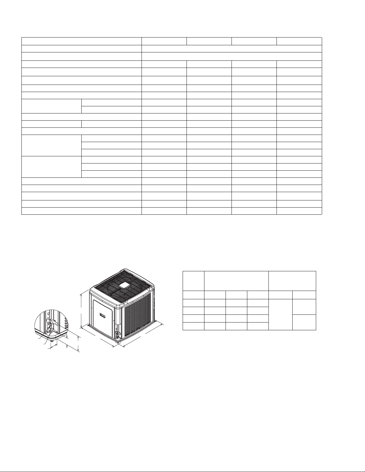
VAPOR
LIQUID
2-3/8
3-1/8
6-1/2
All dimensions are in inches. They are subject to change without
notice. Certified dimensions will be provided upon request.
Unit
Model
Dimensions
(Inches)
Refrigerant
Connection
Service Valve Size
A B C Liquid Vapor
24 39-1/2 42 34
A
36 39-1/2 42 34
48 39-1/2 42 34
3/8”
60 39-1/2 42 34
C
B
3/4”
7/8”
2 Johnson Controls Unitary Products
350154-YTG-B-0408
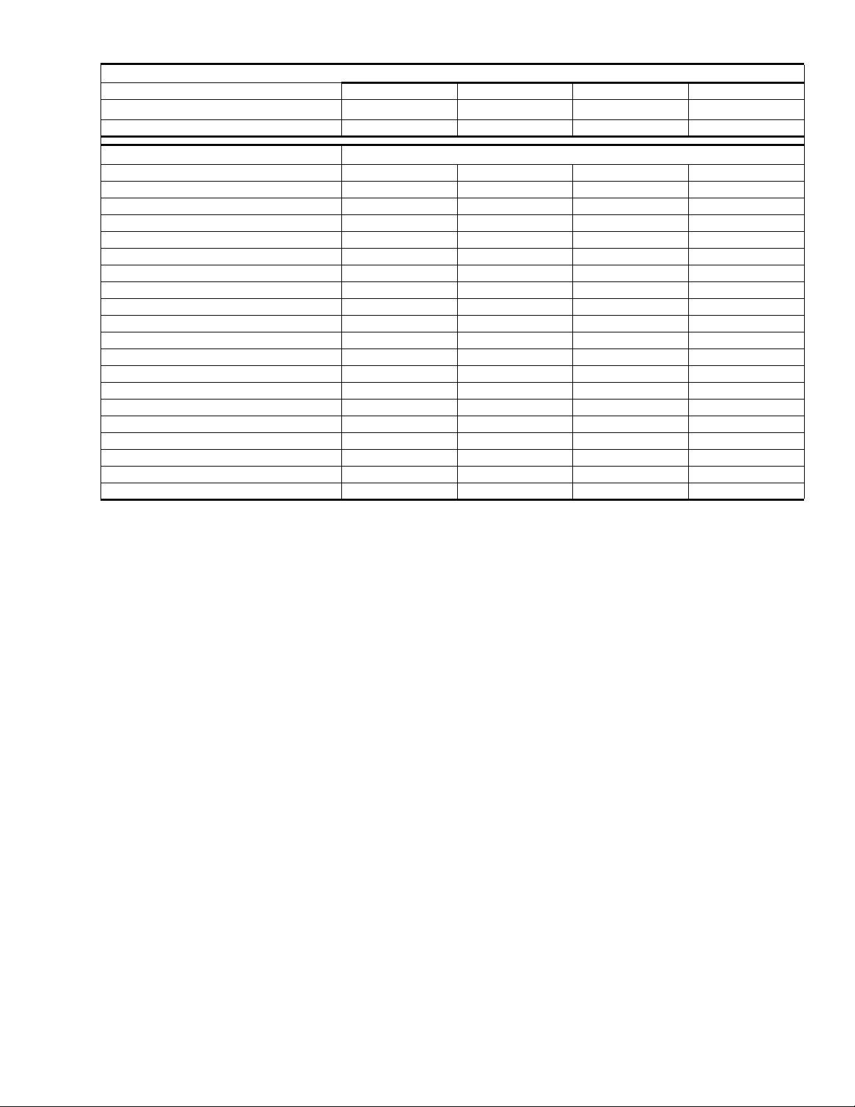
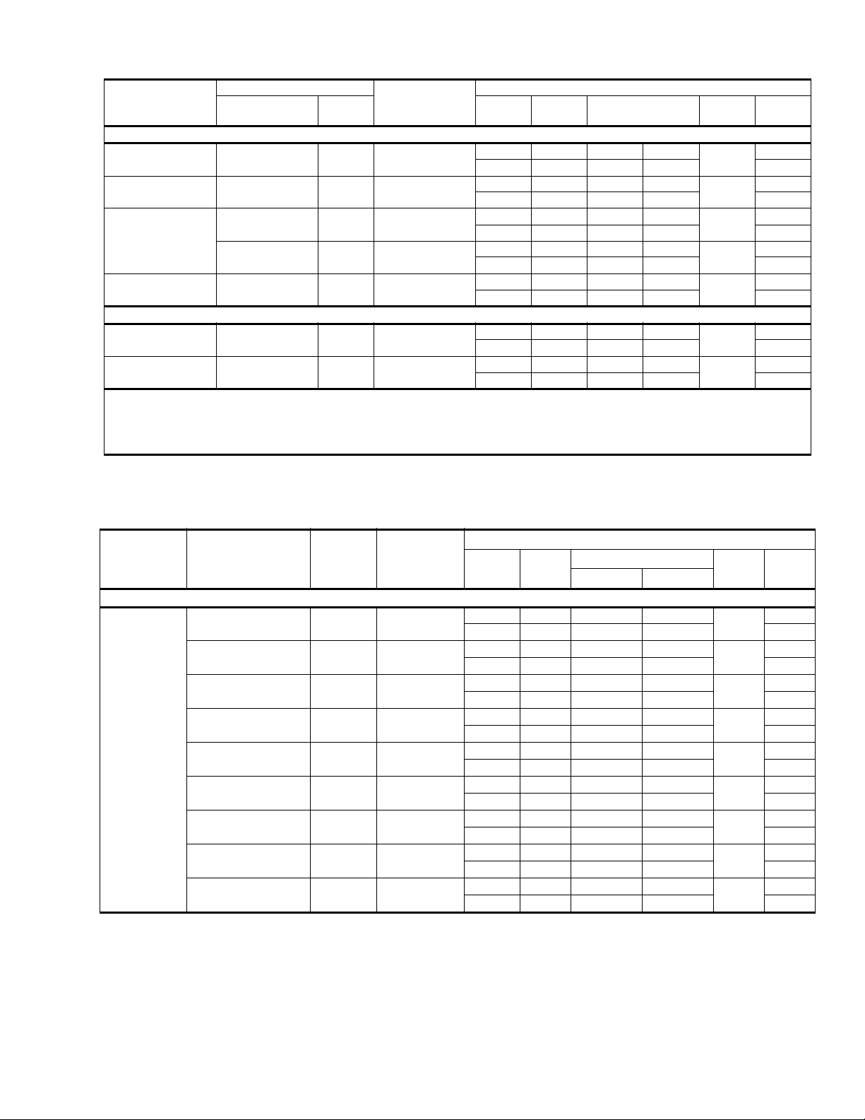
Additional R-410A Charge / TXV Size for Various Matched Systems
Outdoor Unit CZH02411 CZH03611 CZH04811 CZH06011
Approved System Thermal Expansion Valve
Factory R-410A Charge, lbs-oz 16 - 2 15 - 14 13 - 8 14 - 1
Indoor Coil
FC/MC/PC32A 1 – – –
FC/MC/PC35B 0 – – –
FC/MC/PC35C 0 – – –
FC/MC/PC37A 7 24 – –
FC/MC/PC43B 7 24 – –
FC/MC/PC43C 7 24 – –
FC/MC/PC48C 17 7 10 –
FC/MC/PC48D 17 7 10 –
FC/PC60C –––0
FC/MC/PC60D –––0
FC/MC62D – 39 15 12
HC36B 0 – – –
HC42C – 24 – –
HC60D – – 1 0
UC48D 17 7 10 –
UC60D –––0
AV36C 7 0 – –
AV/SV48D – – 1 –
AV/SV60D – – 0 0
F4FV060D – – 1 0
FOOTNOTES:
PROCEDURES:
2
1 Systems matched with furnace or air handlers not equipped with blower-off delays may require blower Time Delay Kit 2FD06700224.
2 PC coils cannot be used in downflow or horizontal applications. FC coils cannot be used in horizontal applications.
3 A TXV kit must be used with these coils to obtain system performance.
Note: If a TXV is factory installed on the coil, it must be replaced with the listed TXV.
1. Unit factory charge listed on the unit nameplate includes refrigerant for the condenser, the smallest evaporator and 15 feet of interconnecting line tubing.
2. Verify the TXV and additional charge required for specific evaporator coil in the system using the above table.
3. Additional charge for the amount of interconnecting line tubing greater than 15 feet at the rate specified on the previous page.
4. Permanently mark the unit nameplate with the total system charge. Total System Charge = Base Charge (as shipped) + adder for
evaporator + adder for line set.
1
1TVM902 1TVM904 1TVM905 1TVM906
TXV Kit3 - Additional Charge, Oz
Johnson Controls Unitary Products 3
350154-YTG-B-0408
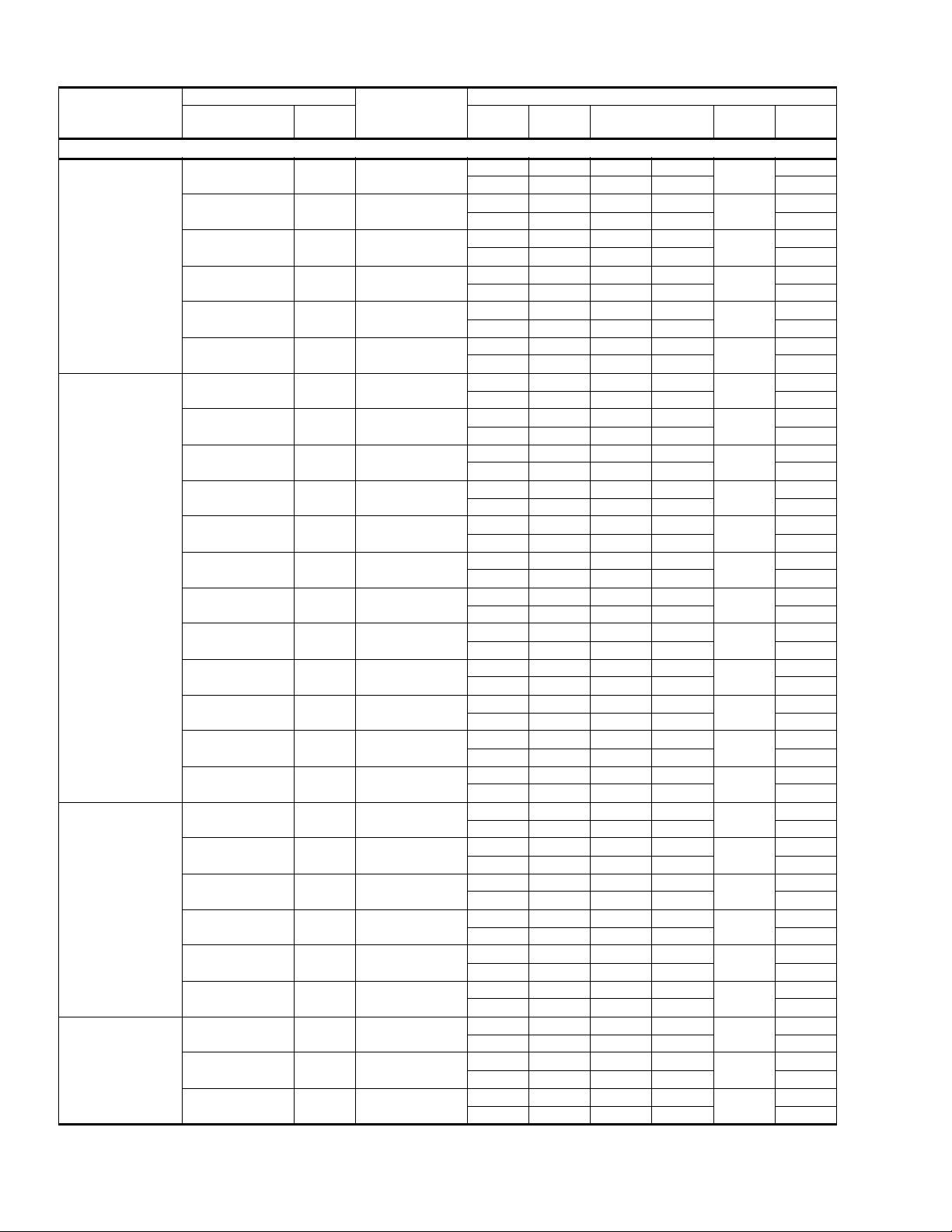
COOLING CAPACITY - With Air Handler Coils
UNIT
MODEL
CZH02411
CZH03611
CZH04811
CZH06011
For notes see Page 5.
AIR HANDLER
MODEL W STAGE
1 PH 18 SEER AC WITH MV
MV12B 17 FC/MC/PC35B
MV12B 17 FC/MC/PC35C
MV12B 17 FC/MC/PC43B
MV12B 17 FC/MC/PC43C
MV12D 24 FC/MC/PC48D
MV12D 24 UC48D
MV12B 17 FC/MC/PC43B
MV12B 17 FC/MC/PC43C
MV16C 21 FC/MC/PC43C
MV12D 24 FC/MC/PC48D
MV12D 24 UC48D
MV16C 21 FC/MC/PC48C
MV16C 21 FC/MC/PC48D
MV16C 21 UC48D
MV20D 24 FC/MC/PC48D
MV20D 24 UC48D
MV12D 24 FC/MC62D
MV20D 24 FC/MC62D
MV16C 21 FC/MC/PC48C
MV16C 21 FC/MC/PC48D
MV16C 21 UC48D
MV20D 24 FC/MC/PC48D
MV20D 24 UC48D
MV20D 24 FC/MC62D
MV20D 24 FC/MC/PC60D
MV20D 24 UC60D
MV20D 24 FC/MC62D
COIL
MODEL
COOLING
1
RATED
CFM
1 620 18.2 13.8
2 800 23.6 17.2 13.80
1 620 18.2 13.8
2 800 23.6 17.2 13.80
1 620 18.5 14.0
2 800 24.0 17.5 14.00
1 620 18.5 14.0
2 800 24.0 17.5 14.00
1 645 18.9 14.3
2 835 24.6 17.9 14.45
1 645 18.9 14.3
2 835 24.6 17.9 14.45
1 775 25.6 18.0
2 1200 36.0 25.2 13.55
1 775 25.6 18.0
2 1200 36.0 25.2 13.55
1 775 25.7 18.1
2 1200 36.2 25.3 14.00
1 735 25.6 18.0
2 1135 36.0 25.2 13.95
1 735 25.6 18.0
2 1135 36.0 25.2 13.95
1 775 25.9 18.2
2 1200 36.4 25.4 14.15
1 775 25.9 18.2
2 1200 36.4 25.4 14.15
1 775 25.9 18.2
2 1200 36.4 25.4 14.15
1 770 25.8 18.1
2 1200 36.6 25.6 14.20
1 770 25.8 18.1
2 1200 36.6 25.6 14.20
1 735 25.7 18.1
2 1135 36.6 25.6 14.25
1 770 25.9 18.2
2 1200 37.0 25.9 14.35
1 1000 34.0 25.1
2 1600 46.0 35.1 12.45
1 1000 34.0 25.1
2 1600 46.0 35.1 12.45
1 1000 34.0 25.1
2 1600 46.0 35.1 12.45
1 1020 34.0 25.1
2 1600 46.0 35.1 12.35
1 1020 34.0 25.1
2 1600 46.0 35.1 12.35
1 1020 34.1 25.2
2 1600 46.5 35.5 12.50
1 1030 40.2 27.3
2 1800 55.5 40.5 11.55
1 1030 40.2 27.3
2 1800 55.5 40.5 11.55
1 1030 42.1 28.6
2 1800 58.0 42.3 12.00
NET MBH SEER EER
17.05
17.05
17.20
17.20
18.00
18.00
17.70
17.70
18.00
18.40
18.40
18.40
18.40
18.40
18.30
18.30
18.50
18.30
17.30
17.30
17.30
17.00
17.00
17.00
15.30
15.30
16.00
14.50
14.50
14.65
14.65
15.25
15.25
14.90
14.90
15.00
15.40
15.40
15.40
15.40
15.40
15.30
15.30
15.40
15.30
14
.20
14.20
14.20
14.00
14.00
14.05
12.55
12.55
13.20
4 Johnson Controls Unitary Products
350154-YTG-B-0408
COOLING CAPACITY - With Air Handler Coils (Continued)
UNIT
MODEL
AIR HANDLER
MODEL W STAGE
COIL
MODEL
1
RATED
CFM
1 PH 18 SEER AC WITH AV/SV
CZH02411 AV36C 21 N / A
CZH03611 AV36C 21 N / A
AV/SV48D 24 N / A
CZH04811
AV/SV60D 24 N / A
CZH06011 AV/SV60D 24 N / A
1 600 18.4 13.9
2 765 23.8 17.3 14.10
1 830 25.7 18.1
2 1270 35.6 24.9 13.45
1 1135 33.1 24.4
2 1610 44.5 34.0 12.10
1 1085 33.0 24.4
2 1655 44.5 34.0 12.10
1 1145 41.5 28.2
2 1765 55.5 40.5 11.65
1 PH 18 SEER AC WITH F*F*
CZH04811 F4FV060 24 N / A
CZH06011 F4FV060 24 N / A
Rated in accordance with DOE test procedures (Federal Register 12-27-79 and 3-18-88) and ARI Standards 210.
Cooling MBH based on 80°F entering air temperature, 50% RH, and rated air flow.
EER (Energy Efficiency Ratio) is the total cooling output in BTU’s at 95°F outdoor ambient divided by the total electric power in watt-hours at those conditions.
SEER (Seasonal Energy Efficiency Ratio) is the total cooling output in BTU’s during a normal annual usage period for cooling divided by the total electric power
input in watt-hours during the same period.
1 1200 33.6 24.8
2 1600 44.5 34.0 12.15
1 1200 41.8 28.4
2 1780 55.5 40.5 11.60
COOLING
NET MBH SEER EER
17.60
18.00
16.60
16.50
15.70
16.85
15.55
14.95
15.25
13.60
13.60
13.00
13.75
12.80
1 MC coils available with a factory installed horizontal drain pan. See price pages for specific model number.
COOLING CAPACITY - With Variable Speed Furnaces
UNIT MODEL
VARIABLE SPEED
FURNACE MODEL
CZH02411
For notes see Page 8.
PV8*A12 14 FC/MC/PC32A
PV9*A12 14 FC/MC/PC32A
P(C,V)9*B12 17 FC/MC/PC35B
P(C,V)9*B12 17 FC/MC/PC35C
PV8*A12 14 FC/MC/PC37A
PV9*A12 14 FC/MC/PC37A
P(C,V)9*B12 17 FC/MC/PC43B
P(C,V)9*B12 17 FC/MC/PC43C
P(C,V)9*B12 17 HC36B
COIL
MODEL
1
W
STAGE
RATED
CFM
TOTAL SENSIBLE
1 PH 18 SEER AC WITH VARIABLE SPEED FURNACES
1 470 17.2 13.0
2 750 23.2 16.9 13.55
1 625 18.1 13.7
2 800 23.2 16.9 13.05
1 560 17.9 13.6
2 820 23.4 17.0 13.45
1 560 17.9 13.6
2 820 23.4 17.0 13.45
1 470 17.4 13.2
2 750 23.6 17.2 13.75
1 625 18.6 14.1
2 800 23.6 17.2 13.30
1 560 18.1 13.7
2 820 24.0 17.5 13.70
1 560 18.1 13.7
2 820 24.0 17.5 13.70
1 560 17.9 13.6
2 820 23.4 17.0 13.55
COOLING
NET MBH
SEER EER
16.70
16.60
17.05
17.05
17.00
17.00
17.35
17.35
17.10
14.15
14.25
14.55
14.55
14.35
14.60
14.70
14.70
14.55
Johnson Controls Unitary Products 5
 Loading...