


J
SPLIT-SYSTEM HEAT PUMPS
OUTDOOR UNITS
|
INSTALLATION INSTRUCTION Supersedes: 035-16192-000 (0601) |
035-16192-001-A-1001 |
MODELS E1FB180 & E1FB240
O
O OO
O
O O
O
O
O
GENERAL
The outdoor units are completely piped and wired at the factory and are shipped ready for immediate installation. Only the interconnecting liquid and suction lines, sight glasses, control wiring, and the main power wiring are required to complete the installation. Every unit is dehydrated, evacuated, leak tested and pressure tested at 450 psig before being pressurized with a holding charge of refrigerant-22 for shipment and/or storage.
To eliminate the costly cabinet deterioration problems usually associated with outdoor equipment, all sheet metal parts are constructed of commercial grade (G90) galvanized steel. After fabrication, each part is thoroughly cleaned to remove any grease or dirt from its surfaces. The parts that will be exposed to the weather are then coated with a “desert sand” powder paint to assure a quality finish for many years. This coating system has passed the 750-hour, salt spray test per ASTM Standard B117.
Every unit includes 2 heavy-duty scroll compressors, 2 suction line accumulators, 2 4-way reversing valves with a 24 volt solenoid, 2 outdoor fan motors with inherent protection, and a copper tube/aluminum fin coil that is positioned vertically for better drainage of the water that will condense on it
during the heating cycle.
They also include 2 filter driers, 2 expansion valves and distributors that are only used during the heating cycle plus a check valve to provide the proper flow of refrigerant through the unit during both the cooling and heating cycles.
All controls are located in the front of the unit and are readily accessible for maintenance, adjustment and service. All wiring (Power and Control) can be made through the front of the unit.
REFERENCE
This instruction covers the installation and operation of the basic condensing unit. For information on the installation and operation of the matching indoor units, refer to Installation Instruction part no. 035-16626-000 (form 515.41-N4Y).
All accessories come with a separate Installation Manual.
Refer to Parts Manual for complete listing of replacement parts on this equipment.
All forms may be ordered from:
Standard Register
Norman, OK 73069
Toll Free: Tel. 877-318-9675/Fax. 877-379-7920
INSPECTION
As soon as a unit is received, it should be inspected for possible damage during transit. If damage is evident, the extent of the damage should be noted on the carrier's freight bill. A separate request for inspection by the carrier's agent should be made in writing.
Installer should pay particular attention to the words: NOTE, CAUTION and WARNING. Notes are intended to clarify or make installation easier. Cautions are given to prevent equipment damage. Warnings are given to alert installer that personal injury and/or equipment damage may result if installation procedure is not handled properly.

035-16192-001-A-1001
TABLE OF CONTENTS
GENERAL ............................................................................. |
1 |
REFERENCE ............................................................................. |
1 |
INSPECTION ............................................................................. |
1 |
NOMENCLATURE...................................................................... |
2 |
INSTALLATION |
|
LIMITATIONS ............................................................................. |
3 |
LOCATION |
|
Roof-Top Locations............................................................. |
3 |
Ground Level Locations...................................................... |
3 |
RIGGING AND HANDLING ........................................................ |
3 |
CLEARANCES ........................................................................... |
4 |
COMPRESSOR CRANKCASE HEATER ................................... |
4 |
POWER AND CONTROL WIRING |
|
Power Wiring ...................................................................... |
4 |
Control Wiring ..................................................................... |
4 |
REFRIGERANT PIPING |
|
General Guidelines ............................................................. |
7 |
Line Sizing .......................................................................... |
7 |
Service Valves .................................................................... |
7 |
Installation........................................................................... |
7 |
EXTENDING THE SERVICE PORTS......................................... |
9 |
EVACUATING AND CHARGING ................................................ |
9 |
BALANCE POINT SETTING....................................................... |
9 |
ALTERNATE CHARGING METHODS........................................ |
10 |
OPERATION |
|
GENERAL ............................................................................. |
11 |
SYSTEM SEQUENCE OF OPERATION |
|
Cooling Operation............................................................... |
11 |
Heating Operation............................................................... |
12 |
Defrost Cycle ...................................................................... |
12 |
Operation Below 0°F........................................................... |
13 |
Emergency Heat Operation ................................................ |
13 |
START-UP |
|
CRANKCASE HEATER (10 Ton Unit Only) ................................ |
14 |
PRE-START CHECK .................................................................. |
14 |
INITIAL START-UP ..................................................................... |
14 |
SAFETY FEATURES.................................................................. |
14 |
SECURE OWNER'S APPROVAL............................................... |
14 |
|
MAINTENANCE |
|
CLEANING |
............................................................................. |
14 |
LUBRICATION............................................................................ |
14 |
|
REPLACEMENT PARTS ............................................................ |
14 |
|
NOTICE TO OWNER.................................................................. |
14 |
|
|
LIST OF FIGURES |
|
Figure |
|
|
No. |
Description |
Page |
1 |
Center of Gravity .................................................. |
3 |
2 |
Typical Rigging..................................................... |
4 |
3 |
Typical Field Wiring .............................................. |
5 |
4 |
Unit Dimensions & Clearances ............................ |
6 |
5 |
Extending The Service Ports................................ |
10 |
6 |
Refrigerant Flow Diagram .................................... |
11 |
7 |
Charging Curves EFB180A.................................. |
15 |
8 |
Charging Curves EFB240A.................................. |
15 |
9 |
Heating Mode Charging Chart At 4800 CFM ....... |
16 |
|
EFB180A |
|
10 |
Heating Mode Charging Chart At 6000 CFM ....... |
16 |
|
EFB180A |
|
11 |
Heating Mode Charging Chart At 6600 CFM ....... |
17 |
|
EFB180A |
|
12 |
Heating Mode Charging Chart At 6400 CFM ....... |
17 |
|
EFB240A |
|
13 |
Heating Mode Charging Chart At 7000 CFM ....... |
18 |
|
EFB 240A |
|
14 |
Heating Mode Charging Chart At 7600 CFM ....... |
18 |
|
EFB 240A |
|
|
LIST OF TABLES |
|
Table |
|
|
No. |
Description |
Page |
1 |
Unit Application Data............................................ |
3 |
2 |
Physical Data ....................................................... |
4 |
3 |
Electrical Data ...................................................... |
5 |
4 |
Suction Lines........................................................ |
7 |
5 |
Liquid Lines .......................................................... |
8 |
6 |
Refrigerant Line Charge....................................... |
8 |
|
|
|
|
|
|
|
|
|
|
PRODUCT NOMENCLATURE |
|
|
|
|
|
|
|||||||||||||||
|
|
|
|
|
|
|
|
|
|
|
|
|
|
|
|
|
|
|
|
|
|
|
|
|
|
|
|
|
|
|
|
|
|
|
|
|
E |
|
1 |
|
F |
B |
|
1 |
8 |
0 |
|
A |
|
2 |
5 |
|
|
|
|
|
|
|
|||||
|
PRODUCT CATEGORY |
|
|
|
|
|
|
|
|
|
|
|
|
|
|
|
|
|
|
|
|
|
|
|
|
|
|
|
|
||
|
|
|
|
|
|
|
|
|
|
|
|
|
|
|
|
|
|
|
|
|
|
|
|
|
|||||||
E = Split-System Heat Pump |
|
|
|
|
|
|
|
|
|
|
|
|
|
|
|
|
|
|
|
|
|
|
|
|
|
|
|
VOLTAGE CODE |
|
||
|
Outdoor Unit |
|
|
|
|
|
|
|
|
|
|
|
|
|
|
|
|
|
|
|
|
|
|
|
|
|
|
|
25 = 208/230-3-60 |
|
|
|
|
|
|
|
|
|
|
|
|
|
|
|
|
|
|
|
|
|
|
|
|
|
|
|
|
|
|
|
|
|
|
|
|
|
|
|
|
|
|
|
|
|
|
|
|
|
|
|
|
|
|
|
|
|
|
|
|
||||||
|
|
|
|
|
|
|
|
|
|
|
|
|
|
|
|
|
|
|
|
|
|
|
|
|
|
|
|
|
|
46 = 460-3-60 |
|
|
PRODUCT GENERATION |
|
|
|
|
|
|
|
|
|
|
|
|
|
|
|
|
|
|
|
|
|
|
|
|
|
|
|
|
||
|
|
|
|
|
|
|
|
|
|
|
|
|
|
|
|
|
|
|
|
|
|
|
|
|
|
|
|
|
|
|
|
|
1 = First Generation |
|
|
|
|
|
|
|
|
|
|
|
|
|
|
|
|
|
|
|
|
|
|
|
|
|
|
|
|
||
|
|
|
|
|
|
|
|
|
|
|
|
|
|
|
|
|
|
|
|
|
|
|
|
|
|
FACTORY INSTALLED HEAT |
|||||
|
|
|
|
|
|
|
|
|
|
|
|
|
|
|
|
|
|
|
|
|
|
|
|
|
|
|
|
|
|||
|
|
|
|
|
|
|
|
|
|
|
|
|
|
|
|
|
|
|
|
|
|
|
|
|
|
||||||
|
|
|
|
|
|
|
|
|
|
|
|
|
|
|
|
|
|
|
|
|
|
|
|
|
|
|
|
|
|
|
|
|
|
|
|
|
|
|
|
|
|
|
|
|
|
|
|
|
|
|
|
|
|
|
|
|
|
|
|
|
|
A = Not Applicable |
|
|
|
|
|
|
|
|
|
|
|
|
|
|
|
|
|
|
NOMINAL COOLING |
|
|
|
|
||||||||||
|
|
PRODUCT IDENTIFIER |
|
|
|
|
|
|
|
|
|
|
|||||||||||||||||||
|
|
|
|
|
|
|
|
CAPACITY |
|
|
|
|
|
|
|||||||||||||||||
|
|
FB = Outdoor Unit |
|
|
|
|
|
|
|
|
|
|
|
|
|
|
|
|
|
|
|
||||||||||
|
|
|
|
|
|
|
180 = 15 Ton |
|
|
|
|
|
|
||||||||||||||||||
|
|
|
|
|
|
|
|
|
|
|
|
|
|
|
|
|
|
|
|
|
|
|
|
||||||||
|
|
|
|
|
|
|
|
|
|
|
|
|
|
|
|
|
|
240 = 20 Ton |
|
|
|
|
|
|
|||||||
|
|
|
|
|
|
|
|
|
|
|
|
|
|
|
|
|
|
|
|
|
|
|
|
|
|
|
|
|
|
|
|
2 |
Unitary Products Group |
035-16192-001-A-1001
INSTALLATION
LIMITATIONS
These units must be installed in accordance with all national and local safety codes. If no local codes apply, installation must conform with the appropriate national codes. See Table 1 for unit application data. Units are designed to meet National Safety Code Standards. If components are to be added to a unit to meet local codes, they are to be installed at the dealer's and/or the customer's expense.
TABLE 1 - UNIT APPLICATION DATA
APPLICATION LIMITATIONS |
MIN |
MAX |
Voltage Variation (208/230-3-60) - Volts2 |
187 |
253 |
Voltage Variation (460-3-60) - Volts2 |
414 |
506 |
Ambient Air on Outdoor Coil (Cooling Cycle) - °F |
45 |
115 |
|
|
|
Ambient Air on Indoor Coil (Cooling Cycle) - °F |
68 |
86 |
|
|
|
Ambient Air on Outdoor Coil (Heating Cycle) - °F |
01 |
70 |
Ambient Air on Indoor Coil (Heating Cycle) - °F |
60 |
80 |
1Rated in accordance with ARI Standard 110, utilization range “A”.
2Below 0 °F, the control circuit will lock out the compressor and allow the electric heat accessory to cycle at its standby capacity.
These beams can usually be set directly on the roof. Flashing is not required.
NOTE: On bonded roofs, check for special installation requirements.
GROUND LEVEL LOCATIONS
The units must be installed on a substantial base that will not settle. Any strain on the refrigerant lines may cause a refrigerant leak. Aone-piece concrete slab with footers that extend below the frost line is recommended. The slab should not be tied to the building foundation because noise and vibration will telegraph.
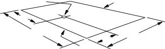
A unit can also be supported by concrete piers. These piers should: (1) extend below the frost line, (2) be located under the unit's four corners and (3) be sized to carry the entire unit weight. Refer to Figure 1 and Table 2 for the center of gravity and unit weight.
A gravel bed or some other means of handling the condensate that will drop from the underside of the unit coil during the heating and defrost cycles may have to be provided.
LOCATION
Use the following guidelines to select a suitable location for these units.
1.The outdoor units must be installed outside the building. The outdoor fans are the propeller type and are not suitable for use with duct work.
APPROXIMATE |
|
BACK |
CENTER OF GRAVITY |
|
|
|
(COIL END) |
|
|
|
|
B |
|
|
76 - 7/8 |
|
|
|
A |
39 - 7/8 |
|
|
|
|
FRONT |
|
2.The outdoor and indoor units should be installed as close together as possible and with a minimum number of bends in the refrigerant piping. Refer to REFRIGERANT PIPING for additional information.
3.The outdoor unit should not be installed beneath windows or between structures where normal operating sounds may be objectionable.
Unit |
Dim. (in.) |
||
A |
B |
||
|
|||
15 Ton |
16 |
38 |
|
20 Ton |
16 |
38 |
|
WARNING: The outdoor unit should not be installed in an area where mud and/or ice could cause personal injury. Remember that condensate will drip from the underside of the unit coils during heat and defrost cycles and that this condensate will freeze when the temperature of the outdoor air is below 32°F.
4.All units require certain clearances for proper operation and service.
On either rooftop or ground level installations, rubber padding can be applied between the base rails and their supports to lessen any transmission of vibration.
ROOF-TOP LOCATIONS
Be careful not to damage the roof. Consult the building contractor or architect if the roof is bonded. Choose a location with adequate structural strength to support the unit.
The unit must be mounted on solid level supports. The supports can be channel iron beams or wooden beams treated to reduce deterioration.
A minimum of two (2) beams are required to support each unit. The beams should: (1) Be positioned perpendicular to the roof joists. (2) Extend beyond the dimensions of the unit to distribute the load on the roof, (3) Be capable of adequately supporting the entire unit weight. Refer to Figure 1 and Table 2 for load distribution and weights.
FIG. 1 - CENTER OF GRAVITY
CAUTION: Care should be taken to protect the unit from tampering and unauthorized persons from injury. Screws on access panels will prevent casual tampering. Additional safety precautions such as fences around the unit or locking devices on the panels may be advisable. Check local authorities for safety regulations.
RIGGING AND HANDLING
Exercise care when moving the unit. Do not remove any packaging until the unit is near the place of installation.
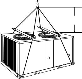
Rig the unit by attaching chain or cable slings with hooks to the round lifting holes provided in the base rails.
CAUTION: Spreaders, longer than the largest dimension across the unit, MUST be used across the top of the unit. See Figure 2.
WARNING: BEFORE LIFTING A UNIT, MAKE SURE THAT ITS WEIGHT IS DISTRIBUTED EQUALLY ON THE CABLES SO THAT IT WILL LIFT EVENLY.
Units may also be moved or lifted with a fork-lift from the front, rear or the compressor end only through the slotted openings provided in the base rails.
Unitary Products Group |
3 |
035-16192-001-A-1001
CAUTION: LENGTH OF FORKS MUST BE A MINIMUM OF 54" (when lifting from the compressor end of the unit) and a MINIMUM OF 42" (when lifting from the front or rear of the unit).
Remove the nesting brackets from the four corners on top of the unit. All screws that are removed to take these brackets off must be replaced on the unit.
CLEARANCES
All units require certain minimum clearances for proper operation and service. Refer to Figure 4 for these clearances.
WARNING: Do not permit overhanging structures or shrubs to obstruct air discharge.
Additional height may be required for snow clearance if winter operation is expected.
COMPRESSOR CRANKCASE HEATER
The compressor is equipped with a crankcase heater to prevent refrigerant from mixing with crankcase oil during the “OFF” cycle. The heaters will be energized when the compressor is not running providing the unit disconnect switch is closed.
TABLE 2 - PHYSICAL DATA
|
DESCRIPTION |
UNIT MODEL |
||
|
|
|
||
|
EFB180 |
EFB240 |
||
|
|
|
||
|
|
|
|
|
Compressor1 |
|
Rating - (Qty) Tons |
(2) 7-1/2 |
(2) 10 |
|
|
Quantity |
2 |
2 |
|
|
|
|
|
Fans |
|
Diameter - inches |
24 |
26 |
|
|
|
|
|
|
Blades/Pitch (°) |
3/32 |
3/36 |
|
|
|
|||
|
|
|
|
|
|
|
Nominal CFM |
10862 |
11395 |
|
|
|
|
|
Fan Motors2 |
|
HP |
1 |
1 |
|
|
|
|
|
|
RPM |
1100 |
1100 |
|
|
|
|||
|
|
|
|
|
|
|
Rows Deep X Rows High |
2 X 40 |
2 X 40 |
|
|
|
|
|
|
|
Finned Length - inches |
130 |
130 |
|
|
|
|
|
|
|
Face Area - square feet |
36.11 |
36.11 |
|
|
|
|
|
|
|
Tube(Copper) OD - inches |
3/8 |
3/8 |
|
|
|
|
|
|
|
Fins (Aluminum) per inch |
18 |
20 |
|
|
|
|
|
|
|
Holding Charge |
1-0/1-0 |
1-0/1-0 |
|
|
(Sys 1 / Sys 2)3 |
||
|
|
|
|
|
|
|
Operating Charge |
16-8/17-8 |
19-0/19-0 |
|
|
(Sys 1 / Sys 2)4 |
||
|
|
|
|
|
|
|
Shipping |
970 |
1020 |
|
|
|
|
|
|
|
Operating |
980 |
1040 |
|
|
|
|
|
1These compressors are fully hermetic.
2The ball bearing, 48 frame, single phase condenser fan motor have internal protection and are directly connected to the condenser fins. Motor rotation is counterclockwise when viewing the lead end, which is opposite the shaft end.
3The amount of charge in the unit as shipped from the factory.
4Total operating charge for the condensing unit, matching indoor unit, and 25 feet of interconnecting pipe.
CAUTION: Do not attempt to start the compressor without at least eight hours of crankcase heat or compressor damage will occur.
5 ft. MIN
|
O |
O |
O |
O |
|
O |
O |
O |
|
O |
|
|
O |
O |
|
FIG. 2 - TYPICAL RIGGING
If a unit has just been installed or the unit disconnect switch has been open for a long period of time, move the system switch on the room thermostat to the “OFF” position before closing the unit disconnect switch. Eight hours of crankcase heat are required to drive the liquid refrigerant out of the compressor before the compressor can be started.
POWER AND CONTROL WIRING
Install electrical wiring in accordance with the latest National Electrical Code (NFPA Standard No. 70) and/or local regulations. The unit should be grounded in accordance with these codes.
POWER WIRING
Check the voltage of the power supply against the data on the unit nameplate. Check the size of the power wire, the disconnect switch and the fuses against the data in Table 3.
NOTE: Copper conductors must be installed between the disconnect switch and the unit.
Refer to Figure 4 for the location of the power wire access opening through the front of the unit. This opening will require a field-supplied conduit fitting.
The field-supplied disconnect switch must be suitable for an outdoor location. Although it should be installed near the unit, do NOT secure it to the unit cabinet.
Refer to Figure 3 for typical field wiring.
CONTROL WIRING
Refer to Figure 4 for the location of the control wire access opening through the front of the unit.
Route the necessary low voltage control wires from terminal block TB2 of the unit control box through this access opening to the indoor unit and to the room thermostat. Refer to Figure 3 for typical field wiring.
The room thermostat should be mounted about 5 feet above the floor and located where it will be exposed to normal room air circulation. Do not locate it on an outside wall, near a supply air grille, or where it may be affected by sunlight
4 |
Unitary Products Group |
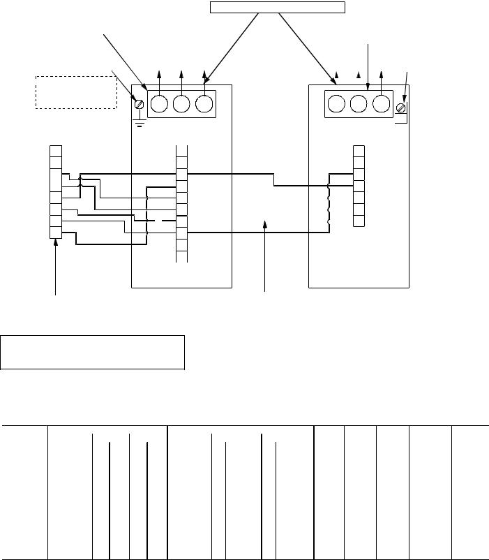
TERMINALS ON:
-Supply Air Blower Motor Contactor 10M
OR
-Terminal Block Electric Heat Control Box
GROUND SCREW
"Heat Pump only" Units
 GROUND LUG
Units with Electric Heat Accessory
035-16192-001-A-1001
3-PHASE LINE VOLTAGE POWER SUPPLY Refer to electrical data to size the power wiring, disconnect switch and overcurrent protection*.
USE COPPER CONDUCTORS ONLY
TERMINALS ON
COMPRESSOR
CONTACTORS 1M &3M
GROUND
LUG
TB1 |
TB2 |
|
|
|
|
|
|
|
|
|
|
|
|
|
|
|
|
|
|
|
|
|
|
R |
|
|
R |
|
|
|
|
|
R |
|
|
|
|
|
|
|
|||
C |
|
|
C |
|
|
|
|
|
C |
|
|
|
|
|
|||||
Y1 |
|
|
O |
|
|
|
|
X |
|
Y2 |
|
|
G |
|
|
|
|
O |
|
O |
|
|
Y1 |
|
|
|
|
Y1 |
|
|
|
|
|
|
|||||
W1 |
|
|
Y2 |
|
|
|
|
|
Y2 |
|
|
|
|
|
|
||||
X |
1 W1 |
|
1 |
|
|
W1 |
|||
|
|
|
|||||||
G |
|
|
X |
|
|
|
|
|
|
|
HR |
|
HC |
TERMINALS ON HEAT |
INDOOR UNIT Control wiring (24-volt) OUTDOOR UNIT |
PUMP THERMOSTAT |
refer to electrical data |
|
to determine the proper |
|
wire size. |
WIRE IN ACCORDANCE WITH LOCAL AND NATIONAL ELECTRICAL CODES
1Only required when an electric heat accessory is used.
*All outdoor units and all heat pump only indoor units require dual element, time delay fuses. Circuit breakers can be used in lieu of fuses for indoor units with an electric heat accessory.
FIG. 3 - TYPICAL FIELD WIRING
TABLE 3 - ELECTRICAL DATA
|
Compressors |
|
|
|
|
Outdoor Fan Motors |
|
Minimum Maximum |
Minimum |
Maximum |
Minimum |
||||||
Model Number |
Power Supply |
System 1 |
System 2 |
|
Power Supply |
|
System 1 |
|
System 2 |
Circuit |
Fuse |
Wire Size |
Wire Length |
Disconnect |
|||
|
RLA |
LRA |
RLA |
LRA |
|
Qty FLA (Each) Qty |
FLA (Each) |
Ampacity |
Size1 |
AWG2 |
feet3 |
Amps |
|||||
|
|
|
|
|
|
|
|
|
|
|
|
|
|
4 AWG |
80 @ 208 V |
|
|
E1FB180A25 |
208/230-3-60 |
32.1 |
195.0 |
32.1 |
195.0 |
208/230-1-60 |
1 |
4.7 |
1 |
4.7 |
81.6 |
90 |
88 @ 230 V |
100 |
|||
|
|||||||||||||||||
2 AWG |
126 @ 208 V |
||||||||||||||||
|
|
|
|
|
|
|
|
|
|
|
|
|
|
|
|||
|
|
|
|
|
|
|
|
|
|
|
|
|
|
140 @ 230 V |
|
||
|
|
|
|
|
|
|
|
|
|
|
|
|
|
|
|
||
E1FB180A46 |
460-3-60 |
16.4 |
95.0 |
16.4 |
95.0 |
460-1-60 |
1 |
2.5 |
1 |
2.5 |
41.9 |
45 |
8 AWG |
142 |
60 |
||
6 AWG |
224 |
||||||||||||||||
|
|
|
|
|
|
|
|
|
|
|
|
|
|
|
|||
|
|
|
|
|
|
|
|
|
|
|
|
|
|
2 AWG |
104 @ 208 V |
|
|
E1FB240A25 |
208/230-3-60 |
42.0 |
239.0 |
42.0 |
239.0 |
208/230-1-60 |
1 |
4.7 |
1 |
4.7 |
103.9 |
110 |
115 @ 230 V |
150 |
|||
|
|||||||||||||||||
0 AWG |
165 @ 208 V |
||||||||||||||||
|
|
|
|
|
|
|
|
|
|
|
|
|
|
|
|||
|
|
|
|
|
|
|
|
|
|
|
|
|
|
182 @ 230 V |
|
||
|
|
|
|
|
|
|
|
|
|
|
|
|
|
|
|
||
E1FB240A46 |
460-3-60 |
19.2 |
125.0 |
19.2 |
125.0 |
460-1-60 |
1 |
2.5 |
1 |
2.5 |
48.2 |
50 |
8 AWG |
111 |
60 |
||
6 AWG |
176 |
||||||||||||||||
|
|
|
|
|
|
|
|
|
|
|
|
|
|
|
|||
1Maximum fuse or maximum circuit breaker (HACR type per NEC).
2Based on three 75°C insulated copper conductors in conduit and ambient of 30°C.
3Based on 5% voltage drop, since unit controls are powered off the unit supply. Two minute time delay between system 1 and system 2.
Unitary Products Group |
5 |

035-16192-001-A-1001
Unit |
Dim. (in.) |
||
A |
B |
||
|
|||
15 Ton |
16 |
38 |
|
20 Ton |
16 |
38 |
|
All dimensions are in inches. They are subject to change without notice. Certified dimensions will be provided upon request.
CENTER OF GRAVITY
Connection |
|
Connection Size |
|
Entry |
|
15 Ton |
20 Ton |
Suction Line |
A |
1-1/8 ID |
1-3/8 ID |
Liquid Line |
B |
5/8 ID |
5/8 ID |
Power Wiring |
C |
2-1/8 KO |
2-1/8KO |
Control Wiring |
D |
7/8 KO |
7/8 KO |
FIG. 4 - UNIT DIMENSIONS AND CLEARANCES
CLEARANCES
Overhead (Top)1 |
120" |
|
Front |
30" |
|
(Piping and Access Panels) |
||
|
||
Left Side |
24" |
|
Right Side |
24" |
|
Rear |
24" |
|
Bottom2 |
0" |
1Units must be installed outdoors. Overhanging structures or shrubs should not obstruct condenser air discharge.
2Adequate snow clearance must be provided if winter operation is expected.
6 |
Unitary Products Group |
 Loading...