


 Loading...
®
TECHNICAL GUIDE
SINGLE PACKAGE GAS/ELECTRIC UNITS AND SINGLE PACKAGE AIR CONDITIONERS
DM 180, 240 & 300
15, 20 & 25 NOMINAL TONS
262259-YTG-F-1009
DESCRIPTION
YORK Sunline 2000™ units are convertible single package high efficiency rooftops. All models have independent dual refrigerant circuits for efficient part load operation. Although the units are primarily designed for curb mounting on a roof, they can also be slab-mounted at ground level or set on steel beams above a finished roof.
All units include:
•Powder Paint finish that meets ASTM-B-117 1000 hour salt spray standards
•Two-stage cooling provided by dual independent refrigeration circuits with expansion valves, filter-driers, high and low pressure/loss of charge switches and freezestats
•Scroll compressors (25T model only)
•Two-stage heating provided by dual independent heat exchangers with aluminized steel tubes, redundant gas valves, spark ignition with induced draft logic
•Permanently lubricated motors
•Bottom or side air discharge configuration capability (field convertible)
•Belt drive blower motor with high static drive option
•Constant supply air volume (CV) with optional variable air volume (VAV)
•Manufactured under the quality standards of ISO9001
•Simplicity® Control Board
•Zero-25% fixed air damper with hood
•Copper tube/aluminum fin coils
•Hinged filter access and tool free latched doors optional
•Hinged tool free blower, blower motor, filters and electrical panel access optional
•Rigging holes in base rails for lifting
•Single point power connection
•Complete factory package - tested, charged and wired
•CSA agency approvals on all units
WARRANTY
•One-year parts warranty
•A Five-year parts warranty on the compressors and electric heat elements
•Ten-year parts warranty on the gas-fired heat exchangers
FOR DISTRIBUTION USE ONLY - NOT TO BE USED AT POINT OF RETAIL SALE
262259-YTG-F-1009
TABLE OF CONTENTS
DESCRIPTION . . . . . . . . . . . . . . . . . . . . . . . . . . . . . 1 TABLE OF CONTENTS. . . . . . . . . . . . . . . . . . . . . . . 2 PRODUCT NOMENCLATURE . . . . . . . . . . . . . . . . . 3 FEATURES . . . . . . . . . . . . . . . . . . . . . . . . . . . . . . . . 4 FACTORY-INSTALLED OPTIONS . . . . . . . . . . . . . . 5 FIELD-INSTALLED ACCESSORIES . . . . . . . . . . . . 7 GUIDE SPECIFICATIONS . . . . . . . . . . . . . . . . . . . 37
|
LIST OF FIGURES |
|
Fig. # |
Pg. # |
|
1 |
UNIT CUTAWAY . . . . . . . . . . . . . . . . . . . . . . . . |
. . . . 5 |
2 |
ALTITUDE/TEMPERATURE CONVERSION |
|
|
FACTOR . . . . . . . . . . . . . . . . . . . . . . . . . . . . . . |
. . . 17 |
3 |
TYPICAL DM FIELD WIRING DIAGRAM . . . . . . |
. . 29 |
4 |
UNIT DIMENSIONS & CLEARANCES 15, 20 & 25 |
|
|
TON . . . . . . . . . . . . . . . . . . . . . . . . . . . . . . . . . . . |
. . 30 |
5 |
REAR VIEW DIMENSIONS . . . . . . . . . . . . . . . . |
. . 31 |
6 |
UNIT DIMENSIONS DM180, 240 & 300 |
|
|
(RAINHOOD) . . . . . . . . . . . . . . . . . . . . . . . . . . . . |
. 32 |
7 |
CENTER OF GRAVITY . . . . . . . . . . . . . . . . . . . . |
. . 33 |
8 |
TYPICAL UNIT APPLICATIONS . . . . . . . . . . . . . |
. . 33 |
9 |
FOUR AND SIX POINT LOADS . . . . . . . . . . . . . |
. . 34 |
10 |
UNIT ROOF CURB DIMENSIONS . . . . . . . . . . . |
. . 35 |
11 |
ROOF CURB DUCT OPENINGS |
|
|
DIMENSION . . . . . . . . . . . . . . . . . . . . . . . . . . . . |
. . 35 |
12 |
CUT AWAY OF ROOF CURB . . . . . . . . . . . . . . . |
. . 35 |
13 |
TYPICAL SIMPLICITY® CONTROL WIRING |
|
|
DIAGRAM . . . . . . . . . . . . . . . . . . . . . . . . . . . . . . |
. . 36 |
|
LIST OF TABLES |
|
Tbl. # |
Pg. # |
|
1 SOUND POWER RATING . . . . . . . . . . . . . . . . . . . . . . . 9 2 CAPACITY RATINGS . . . . . . . . . . . . . . . . . . . . . . . . . . 9 3 GAS HEAT RATIINGS . . . . . . . . . . . . . . . . . . . . . . . . . . 9 4 DM 180 COOLING CAPACITIES (15 TON) . . . . . . . . . 10
5 DM 180 COOLING CAPACITIES (15 TON) (CONTINUED) . . . . . . . . . . . . . . . . . . . . . . . . . . . . . . . 11
6 DM 240 COOLING CAPACITIES (20 TON) . . . . . . . . . 12
7 DM 240 COOLING CAPACITIES (20 TON) (CONTINUED) . . . . . . . . . . . . . . . . . . . . . . . . . . . . . . . 13
Tbl. # |
Pg. # |
8 DM 300 COOLING CAPACITIES (25 TON) . . . . . |
. . . 14 |
9 DM 300 COOLING CAPACITIES (25 TON) (CONTINUED) . . . . . . . . . . . . . . . . . . . . . . . . . . . . . . . 15
10 ALTITUDE CORRECTION FACTORS . . . . . . . . . . . . 16
11SUPPLY AIR BLOWER PERFORMANCE
(15 TON) - COOLING ONLY 180 MBH - BOTTOM
DUCT CONNECTIONS . . . . . . . . . . . . . . . . . . . . . . . . 18
12 SUPPLY AIR BLOWER PERFORMANCE |
|
(20 TON) - COOLING ONLY 240 MBH - BOTTOM |
|
DUCT CONNECTIONS . . . . . . . . . . . . . . . . . . . . . . . . |
19 |
13SUPPLY AIR BLOWER PERFORMANCE
(15 TON) - GAS HEAT 180 MBH - BOTTOM DUCT
CONNECTIONS . . . . . . . . . . . . . . . . . . . . . . . . . . . . . 20
14SUPPLY AIR BLOWER PERFORMANCE
(20 TON) - GAS HEAT 240 MBH - BOTTOM DUCT
CONNECTIONS . . . . . . . . . . . . . . . . . . . . . . . . . . . . . . 21
15 |
SUPPLY AIR BLOWER PERFORMANCE |
|
|
(25 TON) - GAS HEAT 300 MBH - BOTTOM DUCT |
|
|
CONNECTIONS . . . . . . . . . . . . . . . . . . . . . . . . . . . . . |
22 |
16 |
BLOWER MOTOR AND DRIVE DATA . . . . . . . . . . . . |
23 |
17 |
STATIC RESISTANCES . . . . . . . . . . . . . . . . . . . . . . . |
23 |
18 |
POWER EXHAUST PERFORMANCE . . . . . . . . . . . . |
23 |
19 |
DM 180, 240 ELECTRICAL DATA WITHOUT |
|
|
POWERED CONVENIENCE OUTLET . . . . . . . . . . . . |
24 |
20 |
DM 300 ELECTRICAL DATA STANDARD |
|
|
MOTOR WITHOUT POWERED CONVENIENCE |
|
|
OUTLET . . . . . . . . . . . . . . . . . . . . . . . . . . . . . . . . . . . . |
25 |
21DM 300 ELECTRICAL DATA HIGH STATIC MOTOR WITHOUT POWERED CONVENIENCE
OUTLET . . . . . . . . . . . . . . . . . . . . . . . . . . . . . . . . . . . . 25
22 DM 180, 240 ELECTRICAL DATA WITH |
|
POWERED CONVENIENCE OUTLET . . . . . . . . . . . . |
26 |
23DM 300 ELECTRICAL DATA STANDARD MOTOR WITH POWERED CONVENIENCE
OUTLET . . . . . . . . . . . . . . . . . . . . . . . . . . . . . . . . . . . . 27
24DM 300 ELECTRICAL DATA HIGH STATIC MOTOR WITH POWERED CONVENIENCE
OUTLET . . . . . . . . . . . . . . . . . . . . . . . . . . . . . . . . . . . . 27 25 DM VOLTAGE LIMITATIONS . . . . . . . . . . . . . . . . . . . 28 26 PHYSICAL DATA . . . . . . . . . . . . . . . . . . . . . . . . . . . . 28 27 SUPPLY FAN VFD WEIGHTS, IN LBS. . . . . . . . . . . . 29 28 ELECTRIC HEAT CORRECTION FACTORS . . . . . . 29 29 UTILITIES ENTRY DATA . . . . . . . . . . . . . . . . . . . . . . 30 30 MINIMUM CLEARANCES . . . . . . . . . . . . . . . . . . . . . . 32 31 FOUR AND SIX POINT LOADS . . . . . . . . . . . . . . . . . 34
2 |
Johnson Controls Unitary Products |
262259-YTG-F-1009
PRODUCT NOMENCLATURE
15-25 Ton Sunline 2000™ Model Number Nomenclature
D M 180 N24 A 2 A AA 1 0 1 2 4 A
Product Category
D = A/C, Single Pkg., R-22
Product Identifier
M = 8.5-9.0 EER A/C
Nominal Cooling Capacity
180 = 15 Ton
240 = 20 Ton
300 = 25 Ton
Heat Type and Nominal Heat Capacity
C00 = Cooling Only. No field installed electric heat
Gas Heat Options
N24 = 240 MBH Output Aluminized Steel
N32 = 320 MBH Output Aluminized Steel
S24 = 240 MBH Output Stainless Steel
S32 = 320 MBH Output Stainless Steel
Electric Heat Options
E18 = 18 KW
E36 = 36 KW
E54 = 54 KW
E72 = 72 KW
Airflow
A = Std. Motor
B = Std. Motor/Economizer
C = Std. Motor/Economizer/Power Exhaust
(Downflow Only)
D = Std. Motor/Motorized Damper
E = Std. Motor/Motorized Damper/Barometric Relief
J = Std. Motor/Economizer/Barometric Relief
N = Hi Static
P = Hi Static/Economizer
Q = Hi Static/Economizer/Power Exhaust
(Downflow Only)
R = Hi Static/Motorized Damper
K = Hi Static/Motorized Damper/Barometric Relief
S = Hi Static/Economizer/Barometric Relief
Voltage
2 = 208/230-3-60
4 = 460-3-60
5 = 575-3-60
|
|
|
|
|
|
|
|
|
|
|
|
|
|
|
|
|
|
|
|
|
|
|
|
|
|
|
|
|
Product Style |
|
|
|
|
|
|
|
|
|
|
|
|
|
|
|
|
|
|
|
|
|
|
|
|
|
|
|
|
|
|
|
|
|
|
|
|
|
|
|
|
|
|
|
|
|
|
|
|
|
|
A = Style A |
|
|
|
|
|
|
|
|
|
|
|
|
|
|
|
|
|
|
|
|
|
|
|
|
|
|
|
|
|
|
|
|
|
Configuration Options (not required for all units) |
||||
|
|
|
|
|
|
|
|
|
|
|
|
|||||
|
|
|
|
|
|
|
These four digits will not be assigned until a quote is requested, or an order placed. |
|||||||||
|
|
|
|
|
|
|
SS Drain Pan |
|
|
|||||||
|
|
|
|
|
|
|
CPC Controller, DFS, APS |
|
|
|||||||
|
|
|
|
|
|
|
Johnson Controller UNT 1126 (N2 protocol), DFS, APS |
|||||||||
|
|
|
|
|
|
|
Honeywell Controller, DFS, APS |
|
|
|||||||
|
|
|
|
|
|
|
Novar Controller, DFS, APS |
|
|
|||||||
|
|
|
|
|
|
|
Simplicity IntelliComfort Controller |
|
|
|||||||
|
|
|
|
|
|
|
Simplicity IntelliComfort Controller w/ModLinc |
|||||||||
|
|
|
|
|
|
|
York Commercial Comfort System (YCCS) Rtu Controller |
|||||||||
|
|
|
|
|
|
|
Hot Gas Bypass (Standard on VAV, Optional on CV) |
|||||||||
|
|
|
|
|
|
|
Variable Air Volume, VFD (not available with factory installed BAS options) |
|||||||||
|
|
|
|
|
|
|
Variable Air Volume, VFD with ModLINC (not available with factory installed BAS options) |
|||||||||
|
|
|
|
|
|
|
Variable Air Volume, VFD and Manual Bypass (not available with factory installed BAS options) |
|||||||||
|
|
|
|
|
|
|
Variable Air Volume, VFD and Manual Bypass with ModLINC (not available with factory installed BAS options) |
|||||||||
|
|
|
|
|
|
|
Variable Air Volume, VFD (BAS ready) |
|
|
|||||||
|
|
|
|
|
|
|
Variable Air Volume, VFD and Manual Bypass (BAS ready) |
|||||||||
|
|
|
|
|
|
|
Variable Air Volume, VFD Ready (for customer provided, field installed drive) |
|||||||||
|
|
|
|
|
|
|
Variable Air Volume, VFD Ready with ModLINC (for customer-provided, field-installed drive) |
|||||||||
|
|
|
|
|
|
|
2" Pleated filters |
|
|
|||||||
|
|
|
|
|
|
|
4" Pleated filters |
|
|
|||||||
|
|
|
|
|
|
|
BAS Ready Economizer (2-10 V.D.C. Actuator without a controller) |
|||||||||
|
|
|
|
|
|
|
Double Wall Construction |
|
|
|||||||
|
|
|
|
|
|
|
Heat Reclaim Coil Options (2 or 3 Row, 1-5/8" or 2-1/8" Stub Out) (WJ and WR models only) |
|||||||||
|
|
|
|
|
|
|
Any Combination of Additional Options that Don’t Have an Option Code Pre-assigned |
|||||||||
|
|
|
|
|
|
|
|
|
|
|
|
|
|
|
|
|
|
|
|
|
|
Product Generation |
|
|
|
|
|
|
|
||||
|
|
|
|
|
|
|
|
|
|
|
|
|
|
|
|
|
|
|
|
|
|
1 = First Generation |
|
|
|
|
|
|
|
||||
|
|
|
|
|
2 = Second Generation |
|
|
|
|
|
|
|
||||
|
|
|
|
|
|
|
|
|
|
|
|
|
|
|
|
|
|
|
|
|
|
|
|
|
|
|
|
|
|
|
|
|
|
|
|
|
|
|
|
|
|
|
|
|
|
Additional Options |
|
|||
|
|
|
|
|
|
|
|
|
|
|
|
|
|
|||
|
|
|
|
|
|
|
Standard Cabinet |
|
Hinged Filter Door & Tool Free Access Cabinet |
|
||||||
|
|
|
|
|
|
|
|
|
|
|
|
|
|
|
|
|
|
|
|
AA = None |
|
|
|
|
|
|
BA = Hinged Filter Door & Tool Free Access Panels |
|
|||||
|
|
|
AB = Phase Monitor |
|
|
|
|
|
|
BB = Phase Monitor, Hinged Filter Door & Tool Free |
|
|||||
|
|
|
AC = Coil Guard |
|
|
|
|
|
|
Access Panels |
|
|||||
|
|
|
AD = Dirty Filter Switch |
|
|
|
|
|
|
BC = Coil Guard, Hinged Filter Door & Tool Free |
|
|||||
|
|
|
AE = Phase Monitor & Coil Guard |
|
Access Panels |
|
||||||||||
|
|
|
AF = Phase Monitor & Dirty Filter Switch |
|
BD = Dirty Filter Switch, Hinged Filter Door & |
|
||||||||||
|
|
|
AG = Coil Guard & Dirty Filter Switch |
|
Tool Free Access Panels |
|
||||||||||
|
|
|
AH = Phase Monitor, Coil Guard & Dirty Filter Switch |
|
BE = Phase Monitor & Coil Guard, Hinged Filter |
|
||||||||||
|
|
|
RC = Coil Guard & American Flag |
|
Door & Tool Free Access Panels |
|
||||||||||
|
|
|
TA = Technicoat Condenser Coil |
|
BF = Phase Monitor & Dirty Filter Switch, Hinged |
|
||||||||||
|
|
|
TJ = Technicoat Evaporator Coil |
|
Filter Door & Tool Free Access Panels |
|
||||||||||
|
|
|
TS = Technicoat Evaporator & Condenser Coils |
|
BG = Coil Guard & Dirty Filter Switch, Hinged Filter |
|
||||||||||
|
|
|
|
|
|
|
|
|
|
|
|
|
|
|
Door & Tool Free Access Panels |
|
|
|
|
|
|
|
|
|
|
|
|
|
|
|
|
BH = Phase Monitor, Coil Guard & Dirty Filter Switch, |
|
|
|
|
|
|
|
|
|
|
|
|
|
|
|
|
Hinged Filter Door & Tool Free Access Panels |
|
|
|
|
|
|
|
|
|
|
|
|
|
|||||
|
|
|
ZZ = If desired option combination is not listed above, ZZ will be assigned and configuration options will be |
|
||||||||||||
|
|
|
|
located in digits 15-18. |
|
|
||||||||||
|
|
|
|
|
|
|
|
|
|
|
|
|
|
|||
|
|
|
|
|
|
|
|
|
|
|
|
|
||||
|
|
|
|
|
Installation Options |
|
|
|
|
|||||||
|
|
|
|
|
|
|
||||||||||
|
A = No Options Installed |
|
N = Options 2 & 3 |
|
|
|
|
|||||||||
|
B = Option 1 |
|
P = Options 2 & 4 |
|
|
|
||||||||||
|
C = Option 2 |
|
Q = Options 2, 3, & 4 |
|
|
|
||||||||||
|
D = Options 1 & 2 |
|
R = Options 3 & 4 |
|
|
|
||||||||||
|
E = Option 3 |
|
S = Option 5 |
|
|
|
||||||||||
|
F = Option 4 |
|
T = Options 1 & 5 |
|
|
|
||||||||||
|
G = Options 1 & 3 |
|
U = Options 1, 3, & 5 |
|
|
|
||||||||||
|
H = Options 1 & 4 |
|
V = Options 1, 4, & 5 |
|
|
|
||||||||||
|
J = Options 1, 2 & 3 |
|
W = Options 1, 3, 4, & 5 |
|
|
|
||||||||||
|
K = Options 1, 2, & 4 |
|
X = Options 3 & 5 |
|
|
|
||||||||||
|
L = Options 1,3 & 4 |
|
Y = Options 4 & 5 |
|
|
|
||||||||||
|
M = Options 1, 2, 3, & 4 |
|
Z = Options 3, 4 & 5 |
|
|
|
||||||||||
|
|
|
|
|
|
|
|
|
|
|
|
|||||
|
|
|
|
|
|
|
Options |
|
|
|
|
|||||
|
|
|
|
|
|
|
||||||||||
|
1 = Disconnect |
|
4 = Smoke Detector R.A. |
|
|
|
|
|||||||||
|
2 = Non-Pwr'd Conv. Outlet |
|
5 = Pwr'd Conv. Outlet |
|
|
|
||||||||||
|
3 = Smoke Detector S.A. |
|
|
|
|
|
|
|
|
|
||||||
|
|
|
|
|
|
|
|
|
|
|
|
|
|
|
|
|
Johnson Controls Unitary Products |
3 |
262259-YTG-F-1009 |
|
|
|
|
|
|
|
|
FEATURES |
|
• |
Low Ambient - An integrated low-ambient control |
|||||
|
|
|
|
allows all units to operate in the cooling mode down |
||||
All models are available with a wide variety of factory- |
|
|
to 0ºF outdoor ambient without additional assistance. |
|||||
|
|
Optionally, the control board can be programmed to |
||||||
mounted options such as stainless steel heat exchangers, |
|
|
||||||
|
|
lockout the compressors when the outdoor air tem- |
||||||
phase monitor, dirty filter switch, and coil guard to make them |
|
|
||||||
|
|
perature is low or when free cooling is available. |
||||||
suitable for almost every application. |
|
|
||||||
|
|
|
|
|
|
|
||
All units are self-contained and assembled on full perimeter |
• |
|
|
|
|
|
||
|
|
|
|
|
|
|
||
base rails with holes in the four corners for overhead rigging. |
|
|
|
|
|
|
|
|
Every unit is completely piped, wired, charged and tested at |
|
|
|
|
|
|
|
|
|
|
|
|
|
|
|
||
the factory to simplify the field installation and to provide |
|
The Simplicity® control board used in this product will |
|
|||||
years of dependable operation. |
|
effectively operate the cooling system down to 0°F |
|
|||||
All models (including those with an economizer) are suitable |
|
when this product is applied in a comfort cooling |
|
|||||
|
application for people. An economizer is typically |
|
||||||
for either bottom or horizontal duct connections. Models with |
|
|
||||||
|
included in this type of application. When applying this |
|
||||||
factory installed power exhaust are suitable for bottom |
|
|
||||||
|
product for process cooling applications (computer |
|
||||||
duct connections only. For bottom duct, you remove the |
|
|
||||||
|
rooms, switchgear, etc.), please reference applications |
|
||||||
sheet metal panels from the supply and return air openings |
|
|
||||||
|
bulletin AE-011-07 or call the applications department |
|
||||||
through the base of the unit. For horizontal duct, you replace |
|
|
||||||
|
for Unitary Products @ 1-877-UPG-SERV for |
|
||||||
the supply and return air panels on the rear of the unit with a |
|
|
||||||
|
guidance. Additional accessories may be needed for |
|
||||||
side duct flange accessory. |
|
|
||||||
|
stable operation at temperatures below 30°F. |
|
||||||
All models are available with these “factory mounted” outdoor |
|
|
||||||
|
|
|
|
|
|
|
||
|
• |
Anti-Short Cycle Protection - To aid compressor |
||||||
air damper options: |
|
|||||||
• |
Single enthalpy economizer with or without power |
|
|
life, an anti-short cycle delay is incorporated into the |
||||
|
|
standard controls. Compressor reliability is further |
||||||
|
exhaust |
|
|
ensured by programmable minimum run times. For |
||||
• |
BAS-ready economizer with or without power exhaust |
|
|
testing, the anti short cycle delay can be temporarily |
||||
|
|
overridden with the push of a button. |
||||||
• |
Motorized outdoor air damper |
|
|
|||||
|
• |
Lead-Lag - An integrated Lead-Lag option allows |
||||||
• |
Barometric Relief Damper |
|
||||||
|
|
equal run time hours on all compressors, thereby |
||||||
|
|
|
|
|||||
A fixed outdoor air intake assembly will be shipped in the |
|
|
extending the life of all compressors. This option is |
|||||
return air compartment of all units ordered without an econo- |
|
|
selectable on the unit control board. |
|||||
mizer or motorized outdoor air damper option. The assembly |
|
• |
Fan Delays - Fan on and fan off delays are fully pro- |
|||||
includes a rain hood with a damper that can be set for 10, 15 |
|
|||||||
|
|
grammable. Furthermore, the heating and cooling |
||||||
or 25% outdoor air. With bottom duct connections, the intake |
|
|
||||||
|
|
fan delay times are independent of one another. All |
||||||
damper assembly should be mounted over the opening in the |
|
|
||||||
|
|
units are programmed with default values based |
||||||
return air panel. With horizontal ductwork, it should be |
|
|
||||||
|
|
upon their configuration of cooling and heat. |
||||||
mounted on the return air duct. |
|
|
||||||
|
• |
Safety Monitoring - The control board monitors the |
||||||
All supply air blowers are equipped with a belt drive that can be |
|
|||||||
|
|
high and low-pressure switches, the freezestats, the |
||||||
adjusted to meet the exact requirements of the job. A high |
|
|
||||||
|
|
gas valve, if applicable, and the temperature limit |
||||||
static drive option is available for applications with a higher |
|
|
||||||
|
|
switch on gas and electric heat units. The unit con- |
||||||
CFM and/or static pressure requirement. A variable air volume |
|
|
||||||
|
|
trol board will alarm on ignition failures, compressor |
||||||
(VAV) option using a variable frequency drive is available for |
|
|
||||||
|
|
lockouts and repeated limit switch trips. |
||||||
applications requiring a constant supply duct pressure. A differ- |
|
|
||||||
|
• |
Nuisance Trip Protection and Strikes - To prevent |
||||||
ential pressure transducer is used to monitor supply duct static |
|
|||||||
pressure and return a speed reference signal to the VFD to |
|
|
nuisance trouble calls, the control board uses a |
|||||
control the output of the indoor blower motor. |
|
|
“three times, you’re out” philosophy. The high and |
|||||
All compressors include scroll compressors and internal pres- |
|
|
low-pressure switches and the freezestats must trip |
|||||
|
|
three times within two hours before the unit control |
||||||
sure relief. Every refrigerant circuit includes an expansion |
|
|
||||||
|
|
board will lock out the associated compressor. |
||||||
valve, a liquid line filter-drier, a discharge line high pressure |
|
|
||||||
|
• |
On Board Diagnostics - Each alarm will energize a |
||||||
switch and a suction line with a freezestat and low pressure/ |
|
|||||||
loss of charge switch to protect all system components. A hot |
|
|
trouble light on the thermostat, if so equipped, and |
|||||
gas bypass option, consisting of an adjustable compressor |
|
|
flash an alarm code on the control board LED. Each |
|||||
discharge bypass valve, is available for low cooling load |
|
|
high and low-pressure switch alarm as well as each |
|||||
applications. |
|
|
freezestat alarm has its own flash code. The control |
|||||
• |
Simplicity® Controls - Simplicity® control boards have |
|
|
board saves the five most recent alarms in memory, |
||||
|
|
and these alarms can be reviewed at any time. |
||||||
|
standardized a number of features previously available |
|
|
|||||
|
|
|
Alarms and programmed values are retained |
|||||
|
only as options or by utilizing additional controls. |
|
|
|||||
|
|
|
through the loss of power. |
|||||
|
|
|
|
|||||
4 |
|
|
|
|
Johnson Controls Unitary Products |
|||
262259-YTG-F-1009
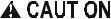
ELECTRIC HEATER LOCATION (OPTIONAL ELECTRIC/ELECTRIC UNITS)
|
|
HIGH EFFICIENCY COMPRESSORS |
|
LONG LASTING |
20 GAUGE ALUMINIZED STEEL |
WITH CRANKCASE HEATERS |
|
COPPER TUBE/ALUMINUM FIN |
|||
POWDER PAINT FINISH |
TUBULAR HEAT EXCHANGERS |
||
|
|
CONDENSER COILS |
ECONOMIZER HOOD
2" DISPOSABLE 
 FILTERS


OUTDOOR AIR OPENING
FOR SLIDE-IN/PLUG-IN
INTERNAL ECONOMIZER(OPTION)
SIDE AND BOTTOM
SUPPLY & RETURN AIR
DUCT OPENINGS(SIDE X SIDE)
1" NPTI
CONDENSATE DRAIN BELT-DRIVE BLOWER MOTOR
FULL PERIMETER 14 GAUGE BASE
RAILS WITH LIFTING HOLES
LOW VOLTAGE RELAY BOARD
AND TERMINAL STRIP
|
ELECTRICAL DISCONNECT |
|
|
MOUNTING LOCATION |
|
|
(Field installed) |
|
|
KNOCKOUT FOR |
|
|
SIDE CONTROL WIRING ENTRY |
|
|
KNOCKOUT FOR |
|
|
SIDE POWER WIRING ENTRY SIDE |
|
|
TERMINAL BLOCK |
|
|
(For Single Point Power Supply |
|
|
with Electric Heat) |
|
|
ELECTRIC\ELECTRIC UNITS |
|
BOTTOM POWER & CONTROL |
||
WIRING ENTRY |
||
KNOCKOUTS FOR SIDE |
||
GAS SUPPLY ENTRY |
||
HOLE FOR BOTTOM |
|
|
GAS SUPPLY ENTRY |
GAS/ELECTRIC |
|
POWER VENTOR MOTOR |
||
WITH POST PURGE CYCLE |
UNIT SHOWN |
|
LOCATION OF VFD (Optional) |
||
|
||
LOCATION OF VFD BYPASS (Optional) |
||
FIGURE 1 - UNIT CUTAWAY
All units have long lasting powder paint cabinets with 1000 hour salt spray test approval under ASTM-B117 procedures.
All models are CSA approved.
•Warranty - All models include a one-year limited parts warranty on the complete unit. Compressors and electric heater elements carry a five-year warranty. Gas heat exchangers carry a 10-year parts warranty.
•Gas Heat Operation - All gas heat units are built with two heating sections for two equal stages of capacity control. Each section includes a durable heat exchanger with aluminized steel or optional stainless steel tubes, a redundant gas valve, spark ignition, power venting, an ignition module for 100% shut-off and all of the safety controls required to meet the latest ANSI standards.
The gas supply piping can be routed into the heating compartment through a hole in the base pan of the unit or through a knockout in the piping panel on the front of the unit.
•Electric Heat Operation - All electric heat models (factory installed only) are wired for a single power source and include a bank of nickel chromium elements mounted at the discharge of the supply air blower to provide a high velocity and uniform distribution of air across the heating elements. Every element is fully protected against excessive current and temperature by fuses and two thermal limit switches.
The power supply wiring can be routed into the control box through a threaded pipe connection in the base pan of the unit or through a knockout in the wiring panel on the front of the unit.
•BAS Controls - York’s Sunline™ series units offer factory
mounted BAS controls such as Simplicity® INTELLI-Com- fort™, Novar®, Honeywell, Johnson, York Commercial Comfort System (YCCS) and CPC.
FACTORY-INSTALLED OPTIONS
•SINGLE INPUT ELECTRONIC ENTHALPY ECONOMIZERS - Includes a slide-in / plug-in damper assembly with fully modulating spring-return motor actuator capable of introducing up to 100% outdoor air with nominal 1% leakage type dampers.
The enthalpy system contains one sensor that monitors the outdoor air and determines when the air is cool enough and dry enough to provide free cooling.
The rainhood is painted to match the basic unit and must be field-assembled before installing.
•BAS-READY ECONOMIZER - Includes a slide-in / plugin damper assembly with fully modulating spring-return motor actuator with zero to 95-degree rotation capable of introducing up to 100% outdoor air with nominal 1% leakage type dampers.
Actuator requires 2-10 VDC input from an external source, such as a field-installed or factory-installed BAS controller. BAS-ready actuators have an adjustable auxiliary end-switch for optional power exhaust control.
For units with optional VAV or Simplicity® Intelli-Com- fort™ control, a factory-installed, dry bulb sensor determines if outdoor air temperature is low enough to provide free-cooling operation. (Field-installed humidity sensors for either outdoor air or outdoor & return air streams are
Johnson Controls Unitary Products |
5 |
262259-YTG-F-1009
available for single enthalpy and differential enthalpy configurations, respectively).
The rainhood is painted to match the basic unit and must be field-assembled before installing.
•POWER EXHAUST - Our economizer options are available with power exhaust. Whenever the outdoor air intake dampers are opened for free cooling, the exhaust fan will be energized to prevent the conditioned space from being over-pressurized during economizer operation. BASready economizer actuators have an adjustable auxiliary end-switch to provide a range of damper positions available to energize power exhaust. For units with optional VAV, power exhaust is energized by means of a binary output signal from the unit's VAV control board.
The exhaust fan, motor and controls are installed and wired at the factory. The rain hood must be assembled and installed in the field.
The power exhaust option can only be used on bottom duct configurations.
•MOTORIZED OUTDOOR AIR INTAKE DAMPER - Includes a slide-in / plug-in damper assembly with a 2- position, spring return motor actuator which opens to a pre-set position whenever the supply air blower is operating and will drive fully closed when the blower unit shuts down.
The rain hood is painted to match the basic unit and must be field assembled before installing.
•BAROMETRIC RELIEF DAMPER - This damper option can be used to relieve internal building air pressure on units with an economizer without power exhaust. This accessory includes a rain hood, a bird screen and a fully assembled damper. With bottom duct connections, the damper should be mounted over the opening in the return air panel. With horizontal ductwork, the accessory should be mounted on the return air duct.
•PHENOLIC COATED EVAPORATOR AND CONDENSER COILS - Special coating process that utilizes Technicoat 10-1" processes. Coating is applied by total immersion of the complete coil for maximum protection.
•ELECTRIC HEATERS wired for single point power supply. These nickel chromium heater elements are provided with limit and automatic reset capability to prevent operation at excessive temperatures.
•VARIABLE AIR VOLUME (VAV) - A factory-installed variable frequency drive (VFD), mounted in the Blower Access compartment, is used to control the speed of the indoor blower motor in order to maintain a constant static pressure in the supply duct. A pressure transducer and VAV control board are mounted inside the control box. The drive comes completely wired and pre-programmed from the factory.
An optional, factory-installed manual bypass switch available with factory-installed VFD can be found in the
Blower Motor Access compartment. The switch can be used to either route power to the VFD for modulating control of the blower motor, to bypass the drive and operate the motor at full speed, or to power the drive (and not the motor) for diagnostic purposes.
Due to space limitations, VAV is not available with any of the factory-installed BAS options described below, but is available with ‘BAS-ready’ models. Terminal blocks are provided in the control box for field wiring of the cus- tomer-installed BAS.
A ‘VFD-ready’ option provides the provisions for a cus- tomer-installed drive. The unit comes with a mounting bracket installed in the Blower Access compartment which may accommodate other vendor’s drives depending on their size. In order to utilize the unit’s mounting bracket, the maximum recommended drive dimensions are as follows:
For 5-hp motor applications ........................ |
10” H x 6” W x 7” D |
For 7.5 thru 15-hp motor applications ......... |
13” H x 8” W x 8” D |
If the drive will not fit in the allotted space, then it will have to be mounted elsewhere; either within the building on a perpendicular wall which is not subjected to excessive temperature, vibration, humidity, dust, corrosive gas, explosive gas, etc., or within an appropriate enclosure rated for outside installation to safeguard against moisture, dust and excessive heat.
A terminal block located in the control box is provided for field connection of the VFD controls.
•HOT GAS BYPASS - To allow for low cooling load operation, a direct-acting pressure-modulating bypass control valve installed on the system #1 discharge line is used to divert high temperature, high pressure refrigerant around the TXV in order to maintain a desired minimum evaporator pressure. HGBP is standard on all units with VAV and optional with CV units.
•FILTER OPTIONS - Standard units are shipped with 2” throw-away filters installed. 2” pleated and 4” pleated filters are offered as a factory installed option.
•CONVENIENCE OUTLET - This 110 volt outlet can be “powered” by the unit with a stepdown transformer or you may order the unit with a “non-powered” convenience outlet that can be wired in the field.
•DISCONNECT SWITCH - For gas heat units and cooling units with electric heat, a HACR breaker sized to the unit is provided. For cooling only units, a switch sized to the largest electric heat available for the particular unit is provided. Factory installed option only.
•BAS - Building Automation System Controls (available on two-system cooling product only).
Simplicity® INTELLI-Comfort™ CONTROL - The York®
Simplicity® INTELLI-Comfort™ control is factory installed. It includes a supply air sensor, a return air sen-
6 |
Johnson Controls Unitary Products |

sor, and an outside air sensor. There are provisions for a field installed dirty filter indicator switch, an air-proving switch, an Outside Air Humidity sensor, a Return Air Humidity sensor, an Inside IAQ sensor, and an Outside Air IAQ sensor. Construction mode operation, 365-day real time clock with 7 day programming plus holiday scheduling is built-in. Two different modes of demand ventilation are achieved through the INTELLI-Comfort™ using CO2 sensors. It uses an inside CO2 sensor to per-
form Demand Ventilation. It can also use an Outside CO2
sensor to perform Differential Demand Ventilation. It uses a Patented Comfort Ventilation algorithm to provide comfortable ventilation air temperature. The patented economizer-loading algorithm will protect the equipment when harsh operating conditions exist. Humidity in the occupied space or return duct can be monitored and controlled via humidity sensors and the on-board connection for hot gas re-heat system. It uses the INTELLIStart™ algorithm to maximize energy savings by recovering the building from the Unoccupied Setpoints to the Occupied Setpoints just in time for the Occupied Time Period to begin. The Simplicity® INTELLI-Comfort™ balances space temperature, ventilation air temperature, CO2 and humidity for ultimate comfort.
Simplicity® INTELLI-Comfort™ with ModLINC CONTROL - The York® Simplicity® INTELLI-Comfort™ with ModLINC control is factory installed. It includes all the features of the INTELLI-Comfort™ control with an additional control to translate communications from MODBUS to the BACnet MSTP protocol.
Novar® BAS CONTROL - The Novar® building automation system controller is factory installed. Includes supply air sensor, return air sensor, dirty filter indicator switch, and air proving switch.
JOHNSON CONTROLS BAS CONTROL - The Johnson Control YK-UNT-1126 building automation system controller is factory installed. Includes supply air sensor, return air sensor, dirty filter indicator switch, and air proving switch.
CPC BAS CONTROL - The Computer Process Controls Model 810-3060 ARTC Advanced Rooftop building automation system controller is factory installed. Includes supply air sensor, return air sensor, dirty filter indicator switch and air proving switch.
HONEYWELL BAS CONTROL - The Honeywell W7750C building automation system controller is factory installed. Includes air supply sensor, return air sensor, dirty filter indicator switch, and air proving switch.
YORK COMMERCIAL COMFORT SYSTEM (YCCS) - Provides rooftop system integration for YCCS single zone, change-over bypass and VAV systems.
•SMOKE DETECTORS - (supply air & return air) The smoke detectors stop operation of the unit by interrupting power to the control board if smoke is detected within the air compartment.
262259-YTG-F-1009
Factory installed smoke detectors in the return air, may be subjected to freezing temperatures during “off” times due to out side air infiltration. these smoke detectors have an operational limit of 32°F to 131°F. smoke detectors installed in areas that could be out side those limitations will have to be moved to prevent having false alarms.
•COIL GUARD - Customers can purchase a coil guard kit to protect the condenser coil from damage. This is not a hail guard kit.
•STAINLESS STEEL HEAT EXCHANGER - For applications in corrosive environments, this option provides a full stainless steel heat exchanger assembly.
•STAINLESS STEEL DRAIN PAN- An optional rust-proof stainless steel drain pan is available to provide years of trouble-free operation in corrosive environments.
•PHASE MONITORS - Designed to prevent unit damage. The phase monitor will shut the unit down in an out-of- phase condition.
•HIGH STATIC DRIVE - May include a belt, blower pulley, motor pulley or a motor change to enhance blower performance.
•DIRTY FILTER SWITCH - This kit includes a differential pressure switch that energizes the fault light on the unit thermostat, indicating that there is an abnormally high pressure drop across the filters. Factory installed option or field installed accessory.
•HINGED FILTER DOOR/”TOOL FREE” BLOWER AND ACCESS PANELS (not hinged) - This option allows for easy access and maintenance.
NOTE:Knobs are shipped separately within the unit to prevent shipping damage. These must be field installed for tool free operation.
•HINGED/"TOOL FREE" BLOWER, BLOWER MOTOR, FILTER AND ELECTRIC ACCESS PANELS - This option allows for complete hinged and tool free access to the unit's blower, blower motor, filters and electrical panel sections.
FIELD-INSTALLED ACCESSORIES
•SINGLE INPUT ELECTRONIC ENTHALPY ECONOMIZERS - Includes a slide-in / plug-in damper assembly with fully modulating spring-return motor actuator capable of introducing up to 100% outdoor air with nominal 1% leakage type dampers.
The enthalpy system contains one sensor that monitors the outdoor air and determines when the air is cool enough and dry enough to provide free cooling.
Johnson Controls Unitary Products |
7 |
262259-YTG-F-1009
The rainhood is painted to match the basic unit and must be field-assembled before installing.
•MOTORIZED OUTDOOR AIR INTAKE DAMPER - Includes a slide-in / plug-in damper assembly with a 2- position, spring return motor actuator which opens to some pre-set position whenever the supply air blower is operating and will drive fully closed when the blower unit shuts down.
The rain hood is painted to match the basic unit and must be field assembled before installing.
•ROOF CURBS - Fourteen-inch high roof curbs provide a water-tight seal between the unit and the finished roof. These full perimeter curbs meet the requirements of the National Roofing Contractors Association (NRCA) and are shipped knocked-down for field assembly.
They're designed to fit inside the base rails of the unit and include both a wood nailing strip and duct hanger supports.
•HIGH ALTITUDE NATURAL GAS - Burner orifices and pilot orifices are provided for proper furnace operation at altitudes up to 6,000 feet.
•PROPANE - Burner orifices, pilot orifices and gas valve parts are provided to convert a natural gas furnace to propane.
•HIGH ALTITUDE PROPANE - Burner orifices and pilot orifices are provided for proper furnace operation at altitudes up to 6,000 feet. This accessory supplements the basic propane conversion kit.
•SIDE DUCT FLANGES - One-inch flanges replace the supply and return air panels on the rear of the unit to accommodate horizontal duct connections. These flanges can also be used individually for bottom supply/ horizontal return or horizontal supply/bottom return. They cannot be used on units with power exhaust.
•BAROMETRIC RELIEF DAMPER - This damper accessory can be used to relieve internal building air pressure on units with an economizer without power exhaust. This accessory includes a rain hood, a bird screen and a fully assembled damper. With bottom duct connections, the damper should be mounted over the opening in the return air panel. With horizontal ductwork, the accessory should be mounted on the return air duct.
•HIGH STATIC DRIVE - May include a belt, blower pulley, motor pulley or a motor change to enhance blower performance.
•ENTHALPY ACCESSORY CONTROL KIT - This kit contains the required components to convert a single enthalpy economizer to dual enthalpy.
•BURGLAR BARS - Mount in the supply and return openings to prevent entry into the duct work.
•FLUE EXHAUST EXTENSION KIT - In locations with wind or weather conditions which may interfere with proper exhausting of furnace combustion products, this kit can be installed to prevent the flue exhaust from entering nearby fresh air intakes.
•WOOD SKID - Allows unit to be handled with 90” forks.
•CO2 SENSOR - Senses CO2 levels and automatically overrides the economizer when levels rise above the present limits.
•COIL GUARD - Customers can purchase a coil guard kit to protect the condenser coil from damage. This is not a hail guard kit.
•PHASE MONITORS - Designed to prevent unit damage. The phase monitor will shut the unit down in an out-of- phase condition.
8 |
Johnson Controls Unitary Products |
|
|
|
|
|
|
|
|
|
|
|
|
|
|
262259-YTG-F-1009 |
||
TABLE 1: SOUND POWER RATING1 |
|
|
|
|
|
|
|
|
|
|
|
|
||||
|
|
ESP |
BLOWER |
|
|
|
|
SOUND POWER (db 10-12 |
Watts) |
|
|
|
||||
UNIT |
|
|
|
|
|
|
|
|
|
|
|
|
|
|||
CFM |
|
|
|
|
|
Octave Band Centerline Frequency (Hz) |
|
SWL |
dB(A) |
|||||||
SIZE |
|
|
|
|
|
|
||||||||||
|
|
|
|
|
|
|
|
|
|
|
|
|
|
@ |
||
|
|
IWG |
RPM |
BHP |
63 |
125 |
|
250 |
500 |
1,000 |
2,000 |
|
4,000 |
8,000 |
dB(A) |
|
|
|
|
|
10Ft.2 |
||||||||||||
|
|
|
|
|
||||||||||||
180 |
6,000 |
1.00 |
1,080 |
4.60 |
99 |
99 |
|
89 |
82 |
84 |
77 |
|
72 |
67 |
89 |
56 |
|
|
|
|
|
|
|
|
|
|
|
|
|
|
|
|
|
240 |
8,000 |
1.00 |
1,120 |
6.65 |
102 |
102 |
|
92 |
85 |
87 |
80 |
|
75 |
70 |
92 |
59 |
|
|
|
|
|
|
|
|
|
|
|
|
|
|
|
|
|
300 |
10,000 |
1.30 |
1160 |
12.5 |
108 |
108 |
|
98 |
91 |
93 |
86 |
|
81 |
76 |
98 |
65 |
|
|
|
|
|
|
|
|
|
|
|
|
|
|
|
|
|
1.These values have been accessed using a model of sound propagation from a point source into the hemispheric\free field. The dBA values provided are to be used for reference only. Calculation of dBA values cover matters of system design and the fan manufacture has no way of knowing the details of each system. This constitutes and expectation to any specification or guarantee requiring a dBA value or sound data in any other form than sound power level ratings.
2.At a distance of 10 feet from the blower.
TABLE 2: CAPACITY RATINGS1
MODEL |
MBH |
EER2 |
IPLV3 |
COOLING ONLY |
|
|
|
DM180C00 |
176 |
8.7 |
9.2 |
DM240C00 |
234 |
8.6 |
8.05 |
DM300C00 |
272 |
8.5 |
9.2 |
COOLING WITH GAS HEAT |
|
|
|
DM180N/S |
176 |
8.5 |
9.0 |
DM240N/S |
232 |
8.5 |
8.05 |
DM300N/S |
272 |
8.5 |
9.0 |
COOLING WITH ELECTRIC HEAT |
|
|
|
DM180E18 |
176 |
8.7 |
9.2 |
DM180E36 |
176 |
8.6 |
9.1 |
DM180E54 |
174 |
8.5 |
8.7 |
DM180E72 |
174 |
8.5 |
8.7 |
DM240E18 |
234 |
8.5 |
8.05 |
DM240E36 |
234 |
8.5 |
8.05 |
DM240E54 |
232 |
8.5 |
8.05 |
DM240E72 |
232 |
8.5 |
8.05 |
DM300E18 |
272 |
8.5 |
9.1 |
DM300E36 |
272 |
8.5 |
9.1 |
DM300E54 |
270 |
8.5 |
9.0 |
DM300E72 |
270 |
8.5 |
9.0 |
1.Certified in accordance with the Unitary Large Equipment certification program AHRI Standard 340/360 (formerly ARI 340/360). (Does Not Include DM300* Models).
2.EER = Energy Efficiency Ratio at full load - the cooling capacity in Btu’s per hour (Btuh) divided by the power input in watts, expressed in Btuh per watt (Btuh/watt).
3.IPLV = Integrated Part Load Value.
TABLE 3: GAS HEAT RATIINGS
MODEL |
MBH INPUT |
MBH OUTPUT |
DM180N/S24 |
300 |
240 |
|
|
|
DM180N/S32 |
400 |
320 |
DM240N/S24 |
300 |
240 |
|
|
|
DM240N/S32 |
400 |
320 |
DM300N/S24 |
300 |
240 |
|
|
|
DM300N/S32 |
400 |
320 |
NOTE: All gas units are two-stage heating. First stage is 50% of total.
S.S.E. = Steady State Efficiency (80%) - output divided by input.
For units with VFD and electric or gas heat, the speed of the indoor blower motor continues to be controlled by duct static pressure via the VAV control board.
If there are VAV boxes present in the duct system, the boxes must be driven to the full-open position using a customer-supplied power source to assure adequate airflow across electric heating elements or gas heat exchanger tubes.
Johnson Controls Unitary Products |
9 |
262259-YTG-F-1009
TABLE 4: DM 180 COOLING CAPACITIES (15 TON)
AIR ON |
|
|
|
|
|
TEMPERATURE OF AIR ON CONDENSER COIL |
|
|
|
|
|
|||||||
|
|
|
75°F |
|
|
|
|
|
|
|
85°F |
|
|
|
|
|||
EVAPORATOR |
|
|
|
|
|
|
|
|
|
|
|
|
|
|
||||
COIL |
|
TOTAL |
POWER |
|
SENSIBLE CAPACITY, MBH |
|
TOTAL |
POWER |
|
SENSIBLE CAPACITY, MBH |
|
|||||||
|
|
ENTERING DRY BULB, °F |
|
|
ENTERING DRY BULB, °F |
|
||||||||||||
|
|
|
CAP.1 |
INPUT2 |
|
|
CAP.1 |
INPUT2 |
|
|
||||||||
CFM |
|
WB |
MBH |
KW |
90 |
85 |
80 |
75 |
70 |
65 |
MBH |
KW |
90 |
85 |
80 |
75 |
70 |
65 |
|
°F |
|||||||||||||||||
|
|
|
|
|
|
|
|
|
|
|
|
|
|
|
|
|
|
|
|
|
77 |
223.2 |
16.6 |
116.8 |
95.5 |
74.1 |
- |
- |
- |
212.0 |
17.5 |
110.9 |
89.5 |
68.2 |
- |
- |
- |
|
|
72 |
206.6 |
15.9 |
143.3 |
121.9 |
100.5 |
79.2 |
- |
- |
195.5 |
16.8 |
137.8 |
116.5 |
95.1 |
73.7 |
- |
- |
4500 |
|
67 |
190.0 |
15.2 |
169.8 |
148.4 |
127.0 |
105.6 |
84.2 |
- |
179.0 |
16.1 |
164.8 |
143.4 |
122.0 |
100.6 |
79.2 |
- |
|
|
62 |
171.6 |
14.8 |
171.6 |
171.6 |
152.5 |
131.1 |
109.8 |
88.4 |
161.6 |
15.6 |
161.6 |
161.6 |
144.7 |
123.3 |
101.9 |
80.6 |
|
|
57 |
171.6 |
14.7 |
171.6 |
171.6 |
158.4 |
137.0 |
115.7 |
94.3 |
161.6 |
15.5 |
161.6 |
161.6 |
148.1 |
126.7 |
105.3 |
83.9 |
|
|
77 |
232.6 |
16.8 |
131.7 |
105.8 |
80.5 |
- |
- |
- |
221.5 |
17.7 |
129.3 |
99.8 |
74.6 |
- |
- |
- |
|
|
72 |
215.3 |
16.1 |
159.8 |
134.5 |
109.3 |
84.0 |
- |
- |
204.3 |
17.0 |
154.6 |
129.3 |
104.0 |
78.8 |
- |
- |
5250 |
|
67 |
198.0 |
15.4 |
187.9 |
163.3 |
138.0 |
112.7 |
87.5 |
- |
187.0 |
16.3 |
179.9 |
158.8 |
133.5 |
108.2 |
83.0 |
- |
|
|
62 |
178.8 |
15.0 |
178.8 |
178.8 |
165.8 |
140.5 |
115.2 |
89.9 |
168.8 |
15.8 |
168.8 |
168.8 |
158.4 |
133.1 |
107.8 |
82.5 |
|
|
57 |
178.8 |
14.9 |
178.8 |
178.8 |
172.2 |
146.9 |
121.7 |
96.4 |
168.8 |
15.7 |
168.8 |
168.8 |
162.0 |
136.8 |
111.5 |
86.2 |
|
|
77 |
242.0 |
17.0 |
146.6 |
116.2 |
87.0 |
- |
- |
- |
231.0 |
17.9 |
147.6 |
110.2 |
81.0 |
- |
- |
- |
|
|
72 |
224.0 |
16.3 |
176.3 |
147.2 |
118.0 |
88.8 |
- |
- |
213.0 |
17.2 |
171.3 |
142.2 |
113.0 |
83.8 |
- |
- |
6000 |
|
67 |
206.0 |
15.6 |
206.0 |
178.2 |
149.0 |
119.8 |
90.7 |
- |
195.0 |
16.5 |
195.0 |
174.2 |
145.0 |
115.8 |
86.7 |
- |
|
|
62 |
186.0 |
15.2 |
186.0 |
186.0 |
179.0 |
149.8 |
120.7 |
91.5 |
176.0 |
16.0 |
176.0 |
176.0 |
172.0 |
142.8 |
113.7 |
84.5 |
|
|
57 |
186.0 |
15.1 |
186.0 |
186.0 |
186.0 |
156.8 |
127.7 |
98.5 |
176.0 |
15.9 |
176.0 |
176.0 |
176.0 |
146.8 |
117.7 |
88.5 |
|
|
72 |
230.0 |
16.5 |
195.9 |
162.7 |
129.5 |
96.2 |
- |
- |
217.9 |
17.4 |
189.6 |
156.3 |
123.1 |
89.9 |
- |
- |
6750 |
|
67 |
211.5 |
15.8 |
211.5 |
197.6 |
163.5 |
130.3 |
97.1 |
- |
199.5 |
16.7 |
199.5 |
189.1 |
158.0 |
124.8 |
91.6 |
- |
|
62 |
191.0 |
15.4 |
191.0 |
191.0 |
187.5 |
154.3 |
121.0 |
87.8 |
180.1 |
16.2 |
180.1 |
180.1 |
178.1 |
144.9 |
111.6 |
78.4 |
|
|
|
|||||||||||||||||
|
|
57 |
191.0 |
15.3 |
191.0 |
191.0 |
191.0 |
157.8 |
124.5 |
91.3 |
180.1 |
16.1 |
180.1 |
180.1 |
180.1 |
146.9 |
113.6 |
80.4 |
|
|
72 |
236.0 |
16.7 |
215.4 |
178.2 |
140.9 |
103.6 |
- |
- |
222.8 |
17.6 |
207.8 |
170.5 |
133.3 |
96.0 |
- |
- |
7500 |
|
67 |
217.0 |
16.0 |
217.0 |
217.0 |
178.0 |
140.7 |
103.5 |
- |
204.0 |
16.9 |
204.0 |
204.0 |
171.0 |
133.7 |
96.5 |
- |
|
62 |
195.9 |
15.6 |
195.9 |
195.9 |
195.9 |
158.7 |
121.4 |
84.2 |
184.1 |
16.4 |
184.1 |
184.1 |
184.1 |
146.9 |
109.6 |
72.3 |
|
|
|
|||||||||||||||||
|
|
57 |
195.9 |
15.5 |
195.9 |
195.9 |
195.9 |
158.7 |
121.4 |
84.2 |
184.1 |
16.3 |
184.1 |
184.1 |
184.1 |
146.9 |
109.6 |
72.3 |
|
|
|
|
|
|
|
|
|
|
|
|
|
|
|
|
|
|
|
AIR ON |
|
|
|
|
|
TEMPERATURE OF AIR ON CONDENSER COIL |
|
|
|
|
|
|||||||
|
|
|
95°F |
|
|
|
|
|
|
|
105°F |
|
|
|
|
|||
EVAPORATOR |
|
|
|
|
|
|
|
|
|
|
|
|
|
|
||||
COIL |
|
TOTAL |
POWER |
|
SENSIBLE CAPACITY, MBH |
|
TOTAL |
POWER |
|
SENSIBLE CAPACITY, MBH |
|
|||||||
|
|
ENTERING DRY BULB, °F |
|
|
ENTERING DRY BULB, °F |
|
||||||||||||
|
|
|
CAP.1 |
INPUT2 |
|
|
CAP.1 |
INPUT2 |
|
|
||||||||
CFM |
|
WB |
MBH |
KW |
90 |
85 |
80 |
75 |
70 |
65 |
MBH |
KW |
90 |
85 |
80 |
75 |
70 |
65 |
|
°F |
|||||||||||||||||
|
|
|
|
|
|
|
|
|
|
|
|
|
|
|
|
|
|
|
|
|
77 |
200.9 |
18.4 |
105.0 |
83.6 |
62.2 |
- |
- |
- |
188.8 |
19.4 |
101.7 |
80.3 |
58.9 |
- |
- |
- |
|
|
72 |
184.4 |
17.7 |
132.4 |
111.0 |
89.6 |
68.2 |
- |
- |
173.2 |
18.6 |
128.2 |
106.8 |
85.5 |
64.1 |
- |
- |
4500 |
|
67 |
168.0 |
17.0 |
159.8 |
138.4 |
117.0 |
95.6 |
74.2 |
- |
157.5 |
17.8 |
153.4 |
133.4 |
112.0 |
90.6 |
69.2 |
- |
|
|
62 |
151.6 |
16.4 |
151.6 |
151.6 |
136.9 |
115.5 |
94.1 |
72.8 |
143.7 |
17.3 |
143.7 |
143.7 |
129.0 |
107.6 |
86.2 |
64.9 |
|
|
57 |
151.6 |
16.3 |
151.6 |
151.6 |
137.7 |
116.4 |
95.0 |
73.6 |
143.7 |
17.3 |
143.7 |
143.7 |
129.4 |
108.0 |
86.7 |
65.3 |
|
|
77 |
210.4 |
18.6 |
126.8 |
93.9 |
68.6 |
- |
- |
- |
196.9 |
19.6 |
126.7 |
90.3 |
65.0 |
- |
- |
- |
|
|
72 |
193.2 |
17.9 |
149.4 |
124.1 |
98.8 |
73.5 |
- |
- |
180.6 |
18.8 |
144.8 |
119.5 |
94.2 |
69.0 |
- |
- |
5250 |
|
67 |
176.0 |
17.2 |
171.9 |
154.3 |
129.0 |
103.7 |
78.5 |
- |
164.3 |
18.0 |
162.2 |
148.7 |
123.5 |
98.2 |
73.0 |
- |
|
|
62 |
158.8 |
16.6 |
158.8 |
158.8 |
151.0 |
125.7 |
100.4 |
75.1 |
149.9 |
17.4 |
149.9 |
149.9 |
142.3 |
117.0 |
91.7 |
66.4 |
|
|
57 |
158.8 |
16.5 |
158.8 |
158.8 |
151.9 |
126.6 |
101.3 |
76.1 |
149.9 |
17.4 |
149.9 |
149.9 |
142.7 |
117.4 |
92.2 |
66.9 |
|
|
77 |
220.0 |
18.8 |
148.6 |
104.2 |
75.0 |
- |
- |
- |
205.0 |
19.8 |
151.6 |
100.2 |
71.0 |
- |
- |
- |
|
|
72 |
202.0 |
18.1 |
166.3 |
137.2 |
108.0 |
78.8 |
- |
- |
188.0 |
19.0 |
161.3 |
132.2 |
103.0 |
73.8 |
- |
- |
6000 |
|
67 |
184.0 |
17.4 |
184.0 |
170.2 |
141.0 |
111.8 |
82.7 |
- |
171.0 |
18.2 |
171.0 |
164.1 |
135.0 |
105.8 |
76.7 |
- |
|
|
62 |
166.0 |
16.8 |
166.0 |
166.0 |
165.0 |
135.8 |
106.7 |
77.5 |
156.0 |
17.6 |
156.0 |
156.0 |
155.5 |
126.3 |
97.2 |
68.0 |
|
|
57 |
166.0 |
16.7 |
166.0 |
166.0 |
166.0 |
136.8 |
107.7 |
78.5 |
156.0 |
17.6 |
156.0 |
156.0 |
156.0 |
126.8 |
97.7 |
68.5 |
|
|
72 |
205.8 |
18.3 |
183.2 |
150.0 |
116.8 |
83.6 |
- |
- |
192.1 |
19.2 |
176.4 |
145.4 |
112.2 |
78.9 |
- |
- |
6750 |
|
67 |
187.5 |
17.6 |
187.5 |
180.6 |
152.5 |
119.3 |
86.1 |
- |
174.8 |
18.4 |
174.8 |
171.3 |
147.0 |
113.8 |
80.6 |
- |
|
62 |
169.2 |
17.0 |
169.2 |
169.2 |
168.7 |
135.4 |
102.2 |
69.0 |
159.4 |
17.8 |
159.4 |
159.4 |
159.2 |
126.0 |
92.8 |
59.5 |
|
|
|
|||||||||||||||||
|
|
57 |
169.2 |
16.9 |
169.2 |
169.2 |
169.2 |
135.9 |
102.7 |
69.5 |
159.4 |
17.8 |
159.4 |
159.4 |
159.4 |
126.2 |
93.0 |
59.8 |
|
|
72 |
209.7 |
18.5 |
200.1 |
162.9 |
125.6 |
88.4 |
- |
- |
196.2 |
19.4 |
191.5 |
158.6 |
121.3 |
84.0 |
- |
- |
7500 |
|
67 |
191.0 |
17.8 |
191.0 |
191.0 |
164.0 |
126.7 |
89.5 |
- |
178.5 |
18.6 |
178.5 |
178.5 |
159.0 |
121.7 |
84.5 |
- |
|
62 |
172.3 |
17.2 |
172.3 |
172.3 |
172.3 |
135.1 |
97.8 |
60.5 |
162.9 |
18.0 |
162.9 |
162.9 |
162.9 |
125.6 |
88.3 |
51.1 |
|
|
|
|||||||||||||||||
|
|
57 |
172.3 |
17.1 |
172.3 |
172.3 |
172.3 |
135.1 |
97.8 |
60.5 |
162.9 |
18.0 |
162.9 |
162.9 |
162.9 |
125.6 |
88.3 |
51.1 |
10 |
Johnson Controls Unitary Products |
262259-YTG-F-1009
TABLE 4: DM 180 COOLING CAPACITIES (15 TON) (CONTINUED)
AIR ON |
|
TEMPERATURE OF AIR ON CONDENSER COIL |
|
|||||||
|
|
|
115°F |
|
|
|
|
|||
EVAPORATOR |
|
|
|
|
|
|
|
|||
COIL |
|
TOTAL |
POWER |
|
SENSIBLE CAPACITY, MBH |
|
||||
|
|
ENTERING DRY BULB, °F |
|
|||||||
|
|
|
CAP.1 |
INPUT2 |
|
|
||||
CFM |
|
WB |
MBH |
KW |
90 |
85 |
80 |
75 |
70 |
65 |
|
°F |
|||||||||
|
|
|
|
|
|
|
|
|
|
|
|
|
77 |
176.8 |
20.4 |
98.3 |
77.0 |
55.6 |
- |
- |
- |
|
|
72 |
161.9 |
19.5 |
124.1 |
102.7 |
81.3 |
59.9 |
- |
- |
4500 |
|
67 |
147.0 |
18.6 |
147.0 |
128.4 |
107.0 |
85.6 |
64.2 |
- |
|
|
62 |
135.8 |
18.1 |
135.8 |
135.8 |
121.1 |
99.7 |
78.3 |
56.9 |
|
|
57 |
135.8 |
18.2 |
135.8 |
135.8 |
121.1 |
99.7 |
78.3 |
56.9 |
|
|
77 |
183.4 |
20.5 |
126.5 |
86.6 |
61.3 |
- |
- |
- |
|
|
72 |
167.9 |
19.6 |
140.2 |
114.9 |
89.6 |
64.4 |
- |
- |
5250 |
|
67 |
152.5 |
18.8 |
152.5 |
143.2 |
118.0 |
92.7 |
67.5 |
- |
|
|
62 |
140.9 |
18.3 |
140.9 |
140.9 |
133.6 |
108.3 |
83.0 |
57.7 |
|
|
57 |
140.9 |
18.4 |
140.9 |
140.9 |
133.6 |
108.3 |
83.0 |
57.7 |
|
|
77 |
190.0 |
20.7 |
154.6 |
96.3 |
67.0 |
- |
- |
- |
|
|
72 |
174.0 |
19.8 |
156.3 |
127.2 |
98.0 |
68.8 |
- |
- |
6000 |
|
67 |
158.0 |
18.9 |
158.0 |
158.0 |
129.0 |
99.8 |
70.7 |
- |
|
|
62 |
146.0 |
18.4 |
146.0 |
146.0 |
146.0 |
116.8 |
87.7 |
58.5 |
|
|
57 |
146.0 |
18.5 |
146.0 |
146.0 |
146.0 |
116.8 |
87.7 |
58.5 |
|
|
72 |
178.4 |
20.1 |
169.6 |
140.7 |
107.5 |
74.3 |
- |
- |
6750 |
|
67 |
162.0 |
19.2 |
162.0 |
162.0 |
141.5 |
108.3 |
75.1 |
- |
|
62 |
149.7 |
18.6 |
149.7 |
149.7 |
149.7 |
116.5 |
83.3 |
50.1 |
|
|
|
|||||||||
|
|
57 |
149.7 |
18.7 |
149.7 |
149.7 |
149.7 |
116.5 |
83.3 |
50.1 |
|
|
72 |
182.8 |
20.3 |
182.8 |
154.3 |
117.0 |
79.7 |
- |
- |
7500 |
|
67 |
166.0 |
19.4 |
166.0 |
166.0 |
154.0 |
116.7 |
79.5 |
- |
|
62 |
153.4 |
18.9 |
153.4 |
153.4 |
153.4 |
116.1 |
78.9 |
41.6 |
|
|
|
|||||||||
|
|
57 |
153.4 |
19.0 |
153.4 |
153.4 |
153.4 |
116.1 |
78.9 |
41.6 |
1.These capacities are gross ratings. For net capacity, deduct the air blower motor, MBH = 3.415 x KW. Refer to the appropriate Blower Performance Table for the KW of the supply air blower motor.
2.These ratings include the condenser fan motors (Total 1.5 KW) and the compressor motors but not the supply air blower motor.  Nominal Rating
Johnson Controls Unitary Products |
11 |
262259-YTG-F-1009
TABLE 5: DM 240 COOLING CAPACITIES (20 TON)
AIR ON |
|
|
|
|
|
TEMPERATURE OF AIR ON CONDENSER COIL |
|
|
|
|
|
|||||||
|
|
|
75°F |
|
|
|
|
|
|
|
85°F |
|
|
|
|
|||
EVAPORATOR |
|
|
|
|
|
|
|
|
|
|
|
|
|
|
||||
COIL |
|
TOTAL |
POWER |
|
SENSIBLE CAPACITY, MBH |
|
TOTAL |
POWER |
|
SENSIBLE CAPACITY, MBH |
|
|||||||
|
|
ENTERING DRY BULB, °F |
|
|
ENTERING DRY BULB, °F |
|
||||||||||||
|
|
|
CAP.1 |
INPUT2 |
|
|
CAP.1 |
INPUT2 |
|
|
||||||||
CFM |
|
WB |
MBH |
KW |
90 |
85 |
80 |
75 |
70 |
65 |
MBH |
KW |
90 |
85 |
80 |
75 |
70 |
65 |
|
°F |
|||||||||||||||||
|
|
|
|
|
|
|
|
|
|
|
|
|
|
|
|
|
|
|
|
|
77 |
322.5 |
22.3 |
159.6 |
131.1 |
102.6 |
- |
- |
- |
298.6 |
23.9 |
154.3 |
125.8 |
97.3 |
- |
- |
- |
|
|
72 |
291.2 |
21.6 |
194.3 |
165.8 |
137.3 |
108.8 |
- |
- |
272.3 |
22.9 |
188.7 |
160.1 |
131.6 |
103.1 |
- |
- |
6000 |
|
67 |
260.0 |
20.9 |
229.0 |
200.5 |
172.0 |
143.5 |
115.0 |
- |
246.0 |
21.9 |
223.0 |
194.5 |
166.0 |
137.5 |
109.0 |
- |
|
|
62 |
225.8 |
20.3 |
225.8 |
225.8 |
192.7 |
164.2 |
135.7 |
107.2 |
213.1 |
21.3 |
213.1 |
213.1 |
185.3 |
156.8 |
128.3 |
99.7 |
|
|
57 |
225.8 |
19.9 |
225.8 |
225.8 |
194.2 |
165.7 |
137.2 |
108.7 |
213.1 |
20.8 |
213.1 |
213.1 |
190.3 |
161.8 |
133.3 |
104.8 |
|
|
77 |
331.2 |
22.3 |
186.6 |
147.0 |
113.3 |
- |
- |
- |
308.3 |
24.0 |
180.9 |
140.3 |
106.6 |
- |
- |
- |
|
|
72 |
299.1 |
21.6 |
219.0 |
185.3 |
151.6 |
118.0 |
- |
- |
281.1 |
23.0 |
211.7 |
178.0 |
144.3 |
110.6 |
- |
- |
7000 |
|
67 |
267.0 |
20.9 |
251.5 |
223.7 |
190.0 |
156.3 |
122.6 |
- |
254.0 |
22.0 |
242.5 |
215.7 |
182.0 |
148.3 |
114.6 |
- |
|
|
62 |
231.9 |
20.3 |
231.9 |
231.9 |
212.8 |
179.2 |
145.5 |
111.8 |
220.1 |
21.4 |
220.1 |
220.1 |
203.1 |
169.4 |
135.7 |
102.1 |
|
|
57 |
231.9 |
19.9 |
231.9 |
231.9 |
214.6 |
180.9 |
147.2 |
113.5 |
220.1 |
20.9 |
220.1 |
220.1 |
208.7 |
175.0 |
141.3 |
107.6 |
|
|
77 |
340.0 |
22.3 |
213.5 |
162.9 |
124.0 |
- |
- |
- |
318.0 |
24.1 |
207.5 |
154.9 |
116.0 |
- |
- |
- |
|
|
72 |
307.0 |
21.6 |
243.8 |
204.9 |
166.0 |
127.1 |
- |
- |
290.0 |
23.1 |
234.8 |
195.9 |
157.0 |
118.1 |
- |
- |
8000 |
|
67 |
274.0 |
20.9 |
274.0 |
246.9 |
208.0 |
169.1 |
130.2 |
- |
262.0 |
22.1 |
262.0 |
236.9 |
198.0 |
159.1 |
120.2 |
- |
|
|
62 |
238.0 |
20.3 |
238.0 |
238.0 |
233.0 |
194.1 |
155.2 |
116.4 |
227.0 |
21.5 |
227.0 |
227.0 |
221.0 |
182.1 |
143.2 |
104.4 |
|
|
57 |
238.0 |
19.9 |
238.0 |
238.0 |
235.0 |
196.1 |
157.2 |
118.4 |
227.0 |
21.0 |
227.0 |
227.0 |
227.0 |
188.1 |
149.2 |
110.4 |
|
|
72 |
313.5 |
21.9 |
273.3 |
229.1 |
184.8 |
140.5 |
- |
- |
297.7 |
23.5 |
264.6 |
220.3 |
176.0 |
131.8 |
- |
- |
9000 |
|
67 |
279.8 |
21.2 |
279.8 |
266.2 |
231.5 |
187.2 |
142.9 |
- |
269.0 |
22.5 |
269.0 |
256.4 |
222.0 |
177.7 |
133.4 |
- |
|
62 |
243.0 |
20.6 |
243.0 |
243.0 |
240.5 |
196.2 |
151.9 |
107.7 |
233.1 |
21.8 |
233.1 |
233.1 |
230.1 |
185.8 |
141.5 |
97.2 |
|
|
|
|||||||||||||||||
|
|
57 |
243.0 |
20.2 |
243.0 |
243.0 |
241.5 |
197.2 |
152.9 |
108.7 |
233.1 |
21.3 |
233.1 |
233.1 |
233.1 |
188.8 |
144.5 |
100.2 |
|
|
72 |
320.0 |
22.2 |
302.9 |
253.2 |
203.5 |
153.9 |
- |
- |
305.5 |
23.8 |
294.4 |
244.7 |
195.1 |
145.4 |
- |
- |
10000 |
|
67 |
285.5 |
21.5 |
285.5 |
285.5 |
255.0 |
205.3 |
155.6 |
- |
276.0 |
22.8 |
276.0 |
276.0 |
246.0 |
196.3 |
146.6 |
- |
|
62 |
248.0 |
20.9 |
248.0 |
248.0 |
248.0 |
198.3 |
148.6 |
99.0 |
239.1 |
22.2 |
239.1 |
239.1 |
239.1 |
189.4 |
139.8 |
90.1 |
|
|
|
|||||||||||||||||
|
|
57 |
248.0 |
20.5 |
248.0 |
248.0 |
248.0 |
198.3 |
148.6 |
99.0 |
239.1 |
21.7 |
239.1 |
239.1 |
239.1 |
189.4 |
139.8 |
90.1 |
|
|
|
|
|
|
|
|
|
|
|
|
|
|
|
|
|
|
|
AIR ON |
|
|
|
|
|
TEMPERATURE OF AIR ON CONDENSER COIL |
|
|
|
|
|
|||||||
|
|
|
95°F |
|
|
|
|
|
|
|
105°F |
|
|
|
|
|||
EVAPORATOR |
|
|
|
|
|
|
|
|
|
|
|
|
|
|
||||
COIL |
|
TOTAL |
POWER |
|
SENSIBLE CAPACITY, MBH |
|
TOTAL |
POWER |
|
SENSIBLE CAPACITY, MBH |
|
|||||||
|
|
ENTERING DRY BULB, °F |
|
|
ENTERING DRY BULB, °F |
|
||||||||||||
|
|
|
CAP.1 |
INPUT2 |
|
|
CAP.1 |
INPUT2 |
|
|
||||||||
CFM |
|
WB |
MBH |
KW |
90 |
85 |
80 |
75 |
70 |
65 |
MBH |
KW |
90 |
85 |
80 |
75 |
70 |
65 |
|
°F |
|||||||||||||||||
|
|
|
|
|
|
|
|
|
|
|
|
|
|
|
|
|
|
|
|
|
77 |
274.7 |
25.5 |
148.9 |
120.4 |
91.9 |
- |
- |
- |
255.9 |
27.0 |
142.4 |
113.9 |
85.4 |
- |
- |
- |
|
|
72 |
253.3 |
24.2 |
183.0 |
154.5 |
126.0 |
97.4 |
- |
- |
236.4 |
25.6 |
177.2 |
148.7 |
120.2 |
91.7 |
- |
- |
6000 |
|
67 |
232.0 |
22.9 |
217.0 |
188.5 |
160.0 |
131.5 |
103.0 |
- |
217.0 |
24.2 |
209.5 |
183.5 |
155.0 |
126.5 |
98.0 |
- |
|
|
62 |
200.4 |
22.3 |
200.4 |
200.4 |
177.9 |
149.4 |
120.8 |
92.3 |
192.0 |
23.5 |
192.0 |
192.0 |
172.2 |
143.7 |
115.1 |
86.6 |
|
|
57 |
200.4 |
21.7 |
200.4 |
200.4 |
186.4 |
157.9 |
129.4 |
100.8 |
192.0 |
23.0 |
192.0 |
192.0 |
179.5 |
151.0 |
122.4 |
93.9 |
|
|
77 |
285.3 |
25.7 |
175.2 |
133.7 |
100.0 |
- |
- |
- |
266.2 |
27.1 |
171.7 |
126.2 |
92.5 |
- |
- |
- |
|
|
72 |
263.2 |
24.4 |
204.4 |
170.7 |
137.0 |
103.3 |
- |
- |
246.0 |
25.7 |
197.5 |
163.8 |
130.1 |
96.4 |
- |
- |
7000 |
|
67 |
241.0 |
23.1 |
233.5 |
207.7 |
174.0 |
140.3 |
106.6 |
- |
225.8 |
24.3 |
222.0 |
201.4 |
167.8 |
134.1 |
100.4 |
- |
|
|
62 |
208.2 |
22.5 |
208.2 |
208.2 |
193.4 |
159.7 |
126.0 |
92.3 |
199.8 |
23.6 |
199.8 |
199.8 |
186.3 |
152.6 |
118.9 |
85.2 |
|
|
57 |
208.2 |
21.9 |
208.2 |
208.2 |
202.7 |
169.0 |
135.3 |
101.6 |
199.8 |
23.1 |
199.8 |
199.8 |
194.2 |
160.5 |
126.8 |
93.1 |
|
|
77 |
296.0 |
25.9 |
201.5 |
146.9 |
108.0 |
- |
- |
- |
276.5 |
27.3 |
201.0 |
138.4 |
99.5 |
- |
- |
- |
|
|
72 |
273.0 |
24.6 |
225.8 |
186.9 |
148.0 |
109.1 |
- |
- |
255.5 |
25.9 |
217.8 |
178.9 |
140.0 |
101.1 |
- |
- |
8000 |
|
67 |
250.0 |
23.3 |
250.0 |
226.9 |
188.0 |
149.1 |
110.2 |
- |
234.5 |
24.5 |
234.5 |
219.4 |
180.5 |
141.6 |
102.7 |
- |
|
|
62 |
216.0 |
22.7 |
216.0 |
216.0 |
209.0 |
170.1 |
131.2 |
92.4 |
207.5 |
23.8 |
207.5 |
207.5 |
200.5 |
161.6 |
122.7 |
83.9 |
|
|
57 |
216.0 |
22.1 |
216.0 |
216.0 |
219.0 |
180.1 |
141.2 |
102.4 |
207.5 |
23.2 |
207.5 |
207.5 |
209.0 |
170.1 |
131.2 |
92.4 |
|
|
72 |
282.0 |
25.0 |
255.8 |
211.6 |
167.3 |
123.0 |
- |
- |
261.2 |
26.2 |
241.1 |
201.2 |
156.9 |
112.6 |
- |
- |
9000 |
|
67 |
258.3 |
23.7 |
258.3 |
246.7 |
212.5 |
168.2 |
123.9 |
- |
239.8 |
24.8 |
239.8 |
232.2 |
202.3 |
158.0 |
113.7 |
- |
|
62 |
223.1 |
23.1 |
223.1 |
223.1 |
219.6 |
175.3 |
131.1 |
86.8 |
212.1 |
24.1 |
212.1 |
212.1 |
208.6 |
164.3 |
120.0 |
75.7 |
|
|
|
|||||||||||||||||
|
|
57 |
223.1 |
22.5 |
223.1 |
223.1 |
224.6 |
180.3 |
136.1 |
91.8 |
212.1 |
23.6 |
212.1 |
212.1 |
212.8 |
168.6 |
124.3 |
80.0 |
|
|
72 |
291.0 |
25.4 |
285.9 |
236.3 |
186.6 |
136.9 |
- |
- |
267.0 |
26.6 |
264.4 |
223.5 |
173.8 |
124.1 |
- |
- |
10000 |
|
67 |
266.5 |
24.1 |
266.5 |
266.5 |
237.0 |
187.3 |
137.6 |
- |
245.0 |
25.2 |
245.0 |
245.0 |
224.0 |
174.3 |
124.6 |
- |
|
62 |
230.3 |
23.5 |
230.3 |
230.3 |
230.3 |
180.6 |
130.9 |
81.2 |
216.7 |
24.5 |
216.7 |
216.7 |
216.7 |
167.0 |
117.3 |
67.6 |
|
|
|
|||||||||||||||||
|
|
57 |
230.3 |
22.9 |
230.3 |
230.3 |
230.3 |
180.6 |
130.9 |
81.2 |
216.7 |
23.9 |
216.7 |
216.7 |
216.7 |
167.0 |
117.3 |
67.6 |
12 |
Johnson Controls Unitary Products |
Loading...