


|
|
|
® |
SUNLINE 2000ä |
|
|
|||
|
|
|
|
|
|
|
|||
|
|
|
|
|
GAS / ELECTRIC |
|
|
||
|
|
|
|
|
SINGLE PACKAGE AIR CONDITIONERS |
||||
|
|
|
|
|
|||||
INSTALLATION INSTRUCTION |
Supersedes: 530.18-N8Y (295) |
|
530.18-N8Y (1096) |
||||||
|
|
|
|
MODELS D7CG 036, 048 & 060 (10 SEER) |
035-14838 |
|
|||
|
|
|
|
|
MODEL D2CG 072 (9 EER) |
|
|
||
|
|
|
|
|
(STYLE A & Belt Drive Option) |
|
|
||
|
|
|
|
|
|
|
|
||
|
|
|
CAUTION |
|
|
FOR YOUR SAFETY |
|
||
|
|
SCROLL COMPRESSORS |
|
|
Do not store or use gasoline or |
|
|||
|
|
OPERATE IN ONLY ONE |
|
|
|
||||
|
|
|
|
other flammable vapors or liquids |
|
||||
|
|
DIRECTION. |
|
|
|
||||
|
|
If the compressor is |
|
|
in the vicinity of this or any other |
|
|||
|
|
experiencing: |
|
|
appliance. |
|
|
||
|
|
- low amperage draw |
|
|
|
|
|||
|
|
|
|
If you smell gas: |
|
|
|||
|
|
- similar discharge and |
|
|
|
|
|||
|
|
|
|
1. Open windows |
|
|
|||
|
|
|
suction pressure |
|
|
|
|
||
|
|
- increased noise level |
|
|
2. Don’t touch electrical switches. |
|
|||
|
|
It is operating in reverse. |
|
|
3. Extinguish any open flame. |
|
|||
|
|
|
|
4. Immediately call your gas supplier. |
|
||||
|
|
Switch two line voltage |
|
|
|
||||
|
|
connections to correct. |
|
|
|
|
|
|
|
|
|
|
|
|
|
|
|
|
|
GENERAL
YORK Model DCG units are single package air conditioners with gas heat designed for outdoor installation on a roof top or a slab.
The units are completely assembled on rigid, permanently attached base rails. All piping, refrigerant charge, and electrical wiring is factory-installed and tested. The units require only electric power, gas piping and duct connections at the point of installation.
The gas-fired heaters have aluminized steel tubular heat exchangers and spark ignition with intermittent pilot.
This appliance is not to be used for temporary heating of buildings or structures under construction.
INSPECTION
As soon as a unit is received, it should be inspected for possible damage during transit. If damage is evident, the extent of the damage should be noted on the carrier’s freight bill. A separate request for inspection by the carrier’s agent should be made in writing. Refer to Form 50.15-NM for additional information.
REFERENCE
∙ |
530.18-N1.12V -Motorized Outdoor Air Damper Accy. |
∙ |
530.18-N1.8V -Coil Guard |
∙530.18-N2.11V -Low NOx Accessory
∙530.18-N8.2V -High Altitude Accy. (Natural Gas)
∙530.18-N8.3V -High Altitude Accy. (Propane)
∙530.18-N8.4V -Gas Piping Accessory
∙530.18-N8.12V -Propane Conversion Accessor
∙690.15-N25V -Low Ambient Accessory
Renewal Parts:
∙Refer to Parts Manual for complete listing of replacement parts on this equipment.
All forms referenced in this instruction may be ordered from:
Publications Distribution Center
Unitary Products Group
P.O. Box 1592, York, PA 17405
APPROVALS
Additional information on the design, installation, operation and |
Design certified by CGA and UL listed as follows: |
service of this equipment is available in the following reference forms: |
|
∙55.70-N1 -General Installation
∙55.70-N2 -Pre-start & Post-start Check List
∙530.18-N1.2V -Economizer Accessory
∙530.18-N1.13V -Man. Outdoor Air Damper Accy 0-35%
∙530.18-N1.14V -Man. Outdoor Air Damper Accy 0-100%
1.For use as a forced air furnace with cooling unit.
2.For outdoor installation only.
3.For installation directly on combustible flooring or, in the U.S.A., on wood flooring or Class A, B, or C roof covering material.
4.For use with natural gas and/or propane (LP) gas.
Not suitable for use with conventional venting systems.
Installer should pay particular attention to the words: NOTE, CAUTION and WARNING. Notes are intended to clarify or make the installation easier. Cautions are given to prevent equipment damage. Warnings are given to alert installer that personal injury and/or equipment damage may result if installation procedure is not handled properly.
CAUTION
THIS PRODUCT MUST BE INSTALLED IN STRICT COMPLIANCE WITH THE ENCLOSED INSTALLATION INSTRUCTIONS AND ANY APPLICABLE LOCAL, STATE, AND NATIONAL CODES INCLUDING, BUT NOT LIMITED TO, BUILDING, ELECTRICAL, AND MECHANICAL CODES
WARNING
INCORRECT INSTALLATION MAY CREATE A CONDITION WHERE THE OPERATION OF THE PRODUCT COULD CAUSE PERSONAL INJURY, PROPERTY DAMAGE AND/OR DEATH.
WARNING
DE-ENERGIZE THE ELECTRICAL POWER AND TURN OFF THE GAS SUPPLY TO THE UNIT BEFORE ATTEMPTING TO INSPECT, REPAIR OR PERFORM MAINTENANCE TO THE UNIT.

530.18-N8Y
TABLE OF CONTENTS
General ................................................................................ |
1 |
Inspection............................................................................. |
1 |
Reference ............................................................................ |
1 |
Approvals ............................................................................. |
1 |
Nomenclature....................................................................... |
2 |
INSTALLATION |
|
Limitations ............................................................................ |
3 |
Location ............................................................................... |
3 |
Rigging and Handling .......................................................... |
3 |
Clearances........................................................................... |
3 |
Ductwork .............................................................................. |
3 |
Filters ................................................................................... |
4 |
Condensate Drain ................................................................ |
4 |
Service Access..................................................................... |
4 |
Thermostat........................................................................... |
4 |
Power and Control Wiring.................................................... |
4 |
Blower Speed Selection....................................................... |
4 |
Scroll Compressors.............................................................. |
4 |
Combustion Discharge ........................................................ |
4 |
Disconnect Switch Bracket For Optional Belt-Drive ............ |
5 |
Gas Piping ........................................................................... |
5 |
Gas Connection ................................................................... |
6 |
L.P. Units, Tanks and Piping ................................................ |
6 |
Low NOx Application............................................................ |
6 |
Vent and Combustion Air Hoods.......................................... |
7 |
Optional Economizer Rain Hood ................................... |
7 & 8 |
OPERATION |
|
Cooling System.................................................................. |
15 |
Cooling Sequence of Operation......................................... |
15 |
Safety Controls (Cooling)................................................... |
15 |
Heating Sequence of Operation ........................................ |
15 |
Safety Controls (Heating) .................................................. |
15 |
Heat Anticipator Setpoints ................................................. |
16 |
Pre-Start Check List........................................................... |
16 |
START-UP |
|
Operating Instructions........................................................ |
16 |
Post-Start Check List (Gas) ............................................... |
16 |
Manifold Gas Pressure Adjustment ................................... |
16 |
Pilot Checkout.................................................................... |
17 |
Burner Instructions............................................................. |
17 |
Burner Air Shutter Adjustment ........................................... |
17 |
Supply Air Blower and Temperature Rise Adjustment ....... |
17 |
Checking Gas Input ........................................................... |
18 |
Secure Owner’s Approval .................................................. |
18 |
MAINTENANCE & TROUBLE SHOOTING
Normal Maintenance.......................................................... |
|
19 |
|
Cleaning Flue Passages and Heating Elements ............... |
|
19 |
|
Troubleshooting ......................................................... |
19 & 20 |
||
|
TABLES |
|
|
No. |
Description |
Page |
|
1 |
Unit Application Data .................................. |
|
3 |
2 |
Gas Heat Application Data.......................... |
|
4 |
3 |
Pipe Sizing ................................................. |
|
5 |
4 |
Static Resistances ...................................... |
|
8 |
5 |
Physical Data.............................................. |
|
9 |
6 |
Supply Air Blower Perf. 3 - 6 Ton Direct-Drive |
9 |
|
7 |
Motor & Drive Data-Belt-Drive Blower ........ |
|
9 |
8 |
Supply Air Blower Perf. 3 & 4 Ton Belt-Drive |
10 |
|
9 |
Supply Air Blower Perf. 5 & 6 Ton Belt-Drive |
11 |
|
10 |
Electrical Data Direct-Drive......................... |
|
12 |
11 |
Electrical Data Belt-Drive............................ |
|
12 |
12 |
Superheat, 036 ........................................... |
|
12 |
13 |
Superheat, 048 ........................................... |
|
13 |
14 |
Superheat, 060 ........................................... |
|
13 |
15 |
Superheat, 072 ........................................... |
|
13 |
16 |
Limit Control Setting ................................... |
|
16 |
17 |
Belt Drive Supply Air Motor Pulley Adj........ |
|
17 |
18 |
Gas Rate - Cubic Feet Per Hour ................ |
|
18 |
|
FIGURES |
|
|
No. |
Description |
Page |
|
1 |
Recommended Drain Piping....................... |
|
4 |
2 |
Typical Field Wiring..................................... |
|
5 |
3 |
External Supply Connection ....................... |
|
6 |
4 |
Bottom Supply Connection ......................... |
|
6 |
5 |
Vent and Combustion Air Hoods................. |
|
7 |
6 |
Economizer Rain Hood Assembly .............. |
|
7 |
7 |
Enthalpy Setpoint Adjustment..................... |
|
8 |
8 |
Center of Gravity......................................... |
|
9 |
9 |
Dimensions and Clearances....................... |
|
14 |
10 |
Gas Valve Piping......................................... |
|
15 |
11 |
Gas Valves.................................................. |
|
16 |
12 |
Proper Flame Adjustment ........................... |
|
17 |
13 |
Typical Flame Appearance ......................... |
|
17 |
14 |
Belt Adjustment ........................................... |
|
17 |
15 |
Press. Drop versus Supply Air CFM ........... |
|
18 |
|
|
|
|
|
|
|
|
|
|
|
|
|
|
|
|
PRODUCT NOMENCLATURE |
|
|
|
|
|
|
|
|
||||||||||||||
|
|
|
|
|
|
|
|
|
|
|
|
|
|
|
|
|
|
|
|
|
|
|
|
|
|
|
|
|
|
|
|
|
|
|
|
|
|
|
|
|
|
|
|
|
|
|
D |
|
|
7 |
|
C |
G |
|
0 |
3 |
6 |
|
N |
|
0 |
4 |
0 |
|
2 |
5 |
|
|
|
|
|||||||
|
|
|
|
|
|
|
|
|
|
|
|
|
|
|
|
|
|
|
|
|
|
|
|
|
|
|
|
|
|
|
|
|
|
|
|
|
|
|
|
PRODUCT CATEGORY |
|
|
|
|
|
|
|
|
|
|
|
|
|
|
|
|
|
|
|
|
|
|
|
|
|
|
|
|
|
|
|
VOLTAGE CODE |
|||||
|
|
|
|
|
|
|
|
|
|
|
|
|
|
|
|
|
|
|
|
|
|
|
|
|
|
|
|
|
|
|
|
|||||||
|
|
|
|
|
|
|
|
|
|
|
|
|
|
|
|
|
|
|
|
|
|
|
|
|
|
|
|
|
|
|
|
|
||||||
|
|
|
|
|
|
|
|
|
|
|
|
|
|
|
|
|
|
|
|
|
|
|
|
|
|
|
|
|
|
|
|
|
|
|
|
|
||
|
D = Single Package Air Conditioner |
|
|
|
|
|
|
|
|
|
|
|
|
|
|
|
|
|
|
|
|
|
|
|
|
|
|
|
|
06 = 208/230-1-60 |
||||||||
|
(Air Cooled) |
|
|
|
|
|
|
|
|
|
|
|
|
|
|
|
|
|
|
|
|
|
|
|
|
|
|
|
|
25 = 208/230-3-60 |
||||||||
|
|
|
|
|
|
|
|
|
|
|
|
|
|
|
|
|
|
|
|
|
|
|
|
|
|
|
|
|
|
|
|
|
|
|
|
46 = 460-3-60 |
||
|
|
|
|
|
|
|
|
|
|
|
|
|
|
|
|
|
|
|
|
|
|
|
|
|
|
|
|
|
|
|
||||||||
|
|
|
|
|
|
|
|
|
|
|
|
|
|
|
|
|
|
|
|
|
|
|
|
|
|
|
|
|
|
|
|
|
|
|
|
58 = 575-3-60 |
||
|
PRODUCT GENERATION |
|
|
|
|
|
|
|
|
|
|
|
|
|
|
|
|
|
|
|
|
|
|
|
|
|
|
|
|
|
|
|
|
|
|
|
|
|
|
|
|
|
|
|
|
|
|
|
|
|
|
|
|
|
|
|
|
|
|
|
|
|
|
|
|
|
|
|
|
|
|
|
|
|
|
|
|
|
2 = 2nd Generation |
|
|
|
|
|
|
|
|
|
|
|
|
|
|
|
|
|
|
|
|
|
|
|
|
|
|
|
|
|
|
|
|
|
NOMINAL GAS HEATING |
|||
|
|
|
|
|
|
|
|
|
|
|
|
|
|
|
|
|
|
|
|
|
|
|
|
|
|
|
|
|
|
|
|
|
|
|
|
OUTPUT CAPACITY |
||
|
7 = 7th Generation |
|
|
|
|
|
|
|
|
|
|
|
|
|
|
|
|
|
|
|
|
|
|
|
|
|
|
|
|
|
|
|
|
|
|
|
||
|
|
|
|
|
|
|
|
|
|
|
|
|
|
|
|
|
|
|
|
|
|
|
|
|
|
|
|
|
|
|
|
|
|
|
|
|
|
040 = 40 MBH |
|
|
|
|
|
|
|
|
|
|
|
|
|
|
|
|
|
|
|
|
|
|
|
|
|
|
|
|
|
|
|
|
|
|
|
|
|
|
|
|
|
|
|
|
|
|
|
|
|
|
|
|
|
|
|
|
|
|
|
|
|
|
|
|
|
|
|
|
|
|
|
|
|
|
|
|
|
060 = 60 MBH |
|
PRODUCT IDENTIFIER |
|
|
|
|
|
|
|
|
|
|
|
|
|
|
|
|
|
|
|
|
|
|
|
|
|
|
|
|
|
||||||||
|
|
|
|
|
|
|
|
|
|
|
|
|
|
|
|
|
|
|
|
|
|
|
|
|
|
|
|
|
|
|
|
|
|
079 = 79 MBH |
||||
|
|
|
|
|
|
|
|
|
|
|
|
|
|
|
|
|
|
|
|
|
|
|
|
|
|
|
|
|
|
|
|
|
|
|||||
|
|
|
|
|
|
|
|
|
|
|
|
|
|
|
|
|
|
|
|
|
|
|
|
|
|
|
|
|
|
|
|
|
|
|
|
|
|
099 = 99 MBH |
|
CG = Gas/Electric |
|
|
|
|
|
|
|
NOMINAL COOLING |
|
|
|
|
|
|
|
|
|
|
|
|
|
|
|
||||||||||||||
|
|
|
|
|
|
|
|
|
|
|
|
|
|
|
|
|
|
|
|
|
|
|
|
|
||||||||||||||
|
|
|
|
|
|
|
|
|
|
CAPACITY |
|
|
|
|
|
|
|
|
|
|
|
|
|
|
|
|
|
|||||||||||
|
|
|
|
|
|
|
|
|
|
|
|
|
|
|
|
|
|
|
|
|
|
|
|
|
|
|
|
|
|
|
|
|||||||
|
|
|
|
|
|
|
|
|
|
|
|
|
036 = 3 Ton |
|
|
FACTORY INSTALLED |
|
|
|
|
||||||||||||||||||
|
|
|
|
|
|
|
|
|
|
|
|
|
048 = 4 Ton |
|
|
|
|
|
HEAT |
|
|
|
|
|
|
|
|
|||||||||||
|
|
|
|
|
|
|
|
|
|
|
|
|
060 = 5 Ton |
|
|
N = Gas Heat Installed |
|
|
|
|
|
|||||||||||||||||
|
|
|
|
|
|
|
|
|
|
|
|
|
072 = 6 Ton |
|
|
|
|
|
|
|||||||||||||||||||
|
|
|
|
|
|
|
|
|
|
|
|
|
|
|
|
|
|
|
|
|
|
|
|
|
|
|
|
|
|
|||||||||
2 |
|
|
|
|
|
|
|
|
|
|
|
|
|
|
|
|
|
|
|
|
|
|
|
|
|
|
|
|
|
|
|
|
|
|
|
|
Unitary Products Group |
|
530.18-N8Y
INSTALLATION
LIMITATIONS
These units must be installed in accordance with the current editions of the following national and local safety codes:
In the U.S.A.:
1.National Electrical Code ANSI/NFPA No. 70.
2.National Fuel Gas Code Z223.1.
3.Gas-Fired Central Furnace Standard ANSI Z21.47-1993.
4.Local gas utility requirements.
In Canada:
1.Canadian Electrical Code CSA C22.1
2.Current Gas Installation Codes CAN/CGA-2.3-M93.
3.Local plumbing and waste water codes.
4.Other applicable local codes.
Refer to Table 1 for Unit Application Data and to Table 2 for Gas Heat Application Data.
If components are to be added to a unit to meet local codes, they are to be installed at the dealer’s and / or the customer’s expense.
Size of unit for proposed installation should be based on heat loss / heat gain calculation made according to the methods of Air Conditioning Contractors of America (ACCA).
TABLE 1 - UNIT APPLICATION DATA
UNIT SIZE |
|
036 |
048 |
060 |
072 |
|
Voltage Variation |
208/230V |
|
187 / 253 |
|
||
|
460V |
|
414 / 504 |
|
||
Min. / Max.1 |
|
|
|
|||
|
575V |
|
518/630 |
|
||
|
|
|
|
|||
Supply Air CFM, Nom. |
|
1200 |
1600 |
2000 |
2400 |
|
Wet Bulb Temperature (°F) of |
57 / 72 |
57 / 72 |
57 / 72 |
57 / 72 |
||
Air on Evaporator Coil, |
|
|||||
Min. / Max. |
|
|
|
|
|
|
Dry Bulb Temperature (°F) of |
45 / 120 |
45 / 120 |
45 / 120 |
45 / 120 |
||
Air on Condenser Coil, |
|
|||||
Min.2 / Max. |
|
|
|
|
|
|
1Utilization range “A” in accordance with ARI Standard 110.
2A low ambient accessory is available for operation down to 0°F.
LOCATION
Use the following guidelines to select a suitable location for these units.
1.Unit is designed for outdoor installation only.
2.Condenser coils must have an unlimited supply of air. Where a choice of location is possible, position the unit on either north or east side of building.
WARNING: Excessive exposure of this furnace to contaminated combustion air may result equipment damage or personal injury. Typical contaminates include: permanent wave solutions, chlorinated waxes and cleaners, chlorine based swimming pool chemicals, water softening chemicals, carbon tetrachloride, Halogen type refrigerants, cleaning solvents (e.g. perchloroethylene), printing inks, paint removers, varnishes, hydrochloric acid, cements and glues, antistatic fabric softeners for clothes dryers, masonry acid washing materials.
3.For ground level installation, a level pad or slab should be used. The thickness and size of the pad or slab used should meet local codes and unit weight. Do not tie the slab to the building foundation.
4.Roof structures must be able to support the weight of the unit and its options and / or accessories. Unit must be installed on a solid level roof curb or appropriate angle iron frame.
CAUTION: If a unit is to be installed on a roof curb or special frame other than a YORK roof curb, gasketing must be applied to all surfaces that come in contact with the unit underside.
5.Maintain level tolerance to 1/2" maximum across the entire length or width of the unit.
6.Elevate the unit sufficiently to prevent any blockage of the air entrances by snow in areas where there will be snow accumulation. Check the local weather bureau for the expected snow accumulation in your area.
RIGGING AND HANDLING
Exercise care when moving the unit. Do not remove any packaging until the unit is near the place of installation. Rig the unit by attaching chain or cable slings to the lifting holes provided in the base rails. Spreaders, whose length exceeds the largest dimension across the unit, MUST be used across the top of the unit.
BEFORE LIFTING A UNIT, MAKE SURE THAT ITS WEIGHT IS DISTRIBUTED EQUALLY ON THE CABLES SO THAT IT WILL LIFT EVENLY.
Units may also be moved or lifted with a forklift. Slotted openings in the base rails are provided for this purpose.
LENGTH OF FORKS MUST BE A MINIMUM OF 42".
Remove the nesting brackets from the four corners on top of the unit. All screws that are removed when taking these brackets off must be replaced on the unit.
CAUTION: An adhesive backed label is provided over the outside of the combustion air inlet opening to prevent moisture from entering the unit which could cause damage to electrical components. Allow this closure label to remain in place until the combustion air hood is to be installed (refer to Figure 5).
Refer to Table 5 for unit weights and to Figure 8 for approximate center of gravity.
CLEARANCES
All units require certain clearances for proper operation and service. Installer must make provisions for adequate combustion and ventilation air in accordance with Section 5.3, Air for Combustion and Ventilation of the National Fuel Gas Code, ANSI Z223.1 (in U.S.A.) or Sections 7.2, 7.3 or 7.4 of Gas Installation Codes CAN/CGA-B149.1 and .2 (in Canada) and/or applicable provisions of the local building codes. Refer to Figure 9 for the clearances required for combustible construction, servicing, and proper unit operation.
WARNING: Do not permit overhanging structures or shrubs to obstruct condenser air discharge outlet, combustion air inlet or vent outlet.
DUCTWORK
Ductwork should be designed and sized according to the methods in Manual Q of the Air Conditioning Contractors of America (ACCA).
A closed return duct system shall be used. This shall not preclude use of economizers or outdoor fresh air intake. The supply and return air duct connections at the unit should be made with flexible joints to minimize the transmission of noise.
Unitary Products Group |
3 |
530.18-N8Y
The supply and return air duct systems should be designed for the CFM and static requirements of the job. They should NOT be sized to match the dimensions of the duct connections on the unit.
CAUTION: When fastening ductwork to the side duct flanges on the unit, insert the screws through the duct flanges only. DO NOT insert the screws through the casing.
Outdoor ductwork must be insulated and waterproofed.
Refer to Figure 9 for information concerning side and bottom supply and return air duct openings.
FILTERS
1" filters are supplied with each unit. 2" replacement filters may be used with no modification to the filter racks. Filters must always be installed ahead of the evaporator coil and must be kept clean or replaced with same size and type. Dirty filters will reduce the capacity of the unit and will result in frosted coils or safety shutdown. Minimum filter area and required sizes are shown in Table 5.
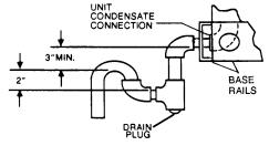
CONDENSATE DRAIN
Plumbing must conform to local codes. Use a sealing compound on male pipe threads. Install a condensate drain line from the 3/4" PVC female connection on the unit to spill into an open drain.
NOTE: The condensate drain line MUST be trapped to provide proper drainage. See Figure 1.
FIG. 1 - RECOMMENDED DRAIN PIPING
SERVICE ACCESS
Access to all serviceable components is provided by the following removable panels:
∙Scroll compressor compartment
∙Burner compartment
∙Blower compartment
∙Main control box
∙Filter compartment
∙Motor access (on units with belt-drive option)
Refer to Figure 9 for location of these access panels.
CAUTION: Make sure that all screws are replaced on the unit to maintain an air-tight seal.
THERMOSTAT
The room thermostat should be located on an inside wall approximately 56" above the floor where it will not be subject to drafts, sun exposure, or heat from electrical fixtures or appliances. Follow manufacturer’s instructions enclosed with thermostat for general installation procedure. Color coded insulated wires (#18 AWG) should be used to connect thermostat to unit. See Figure 2 for wiring details.
NOTE: If the unit has an economizer, remove jumper J1 from terminals 8 and 10 on the relay board to prevent simultaneous operation of the scroll compressor and the economizer. If you want to energize the scroll compressor for supplemental cooling during the economizer operation, use a thermostat with two stages of cooling.
POWER AND CONTROL WIRING
Field wiring to the unit must conform to provisions of the National Electrical Code (NEC), ANSI / NFPA 70-1987 (in U.S.A.) current Canadian Electric Code (CEC) C22.1 (in Canada), and / or local ordinances. The unit must be electrically grounded in accordance with the N.E.C. ANSI / NFPA 70 or local codes.
Voltage tolerances which must be maintained at the compressor terminals during start-up and running conditions are indicated on the unit Rating Plate and Table 1.
The internal wiring harness furnished with this unit is an integral part of a UL and CGA design certified unit. Field alteration to comply with electrical codes should not be required.
A disconnect switch should be field provided for the unit. The switch must be separate from all other circuits. Refer to Figure 9 for installation location. If any of the wire supplied with the unit must be replaced, replacement wire must be of the type shown on the wiring diagram.
Electricallines must besized properlyto carrytheload.USECOPPER CONDUCTORS ONLY. Each unit must be wired with a separate branch circuit fed directly from the meter panel and properly protected.
CAUTION: When connecting electrical power and control wiring to the unit, waterproof type connectors MUST BE USED so that water or moisture cannot be drawn into the unit during normal operation. The above waterproofing conditions will also apply when installing a field-supplied disconnect switch.
Refer to Figure 2 for typical field wiring and to the appropriate unit wiring diagram for control circuit and power wiring information.
BLOWER SPEED SELECTION
Three blower motor speeds are available on the direct-drive units. The speed selection for the direct-drive units is determined by the CFM and ESP requirements of the applications. All units with belt-drive option have an adjustable motor pulley to achieve the above conditions.
All direct-drive units with 208/230 voltage are shipped with the wire labeled #116 connected to the "HIGH" speed tap on the blower motor. If a lower blower motor speed is desired, this wire should be moved to the "MED" or "LOW" speed tap on the motor for the speed desired.
All direct-drive units with 460 and 575 voltage are shipped with the wire labeled #116 connected to the "HIGH" speed tap on the blower motor. If the medium speed is required, connect wire #116 to the "MED" speed tap and the blue motor lead to the "HIGH" speed tap. If the low speed is required, connect wire #116 to the "LOW" speed tap, the blue motor lead to the "HIGH" speed tap and the orange motor lead to the "MED" speed tap.
SCROLL COMPRESSOR
These units are shipped with the scroll compressor mountings factory-adjusted and ready for operation.
CAUTION: Do Not loosen the scroll compressor mounting bolts.
COMBUSTION DISCHARGE
The products of combustion are discharged horizontally through a screened opening on the gas heat access panel.
TABLE 2 - GAS HEAT APPLICATION DATA
Input |
Output |
Available |
Gas Rate |
1 |
Temp. Rise °F |
||
Capacity, |
Capacity, |
on |
|
At Full Input |
2 |
||
(Ft.3/Hr.) |
|
|
|||||
(Mbh) |
(Mbh) |
Models |
|
|
Min. |
Max. |
|
50 |
40 |
3 Ton |
47 |
|
15 |
45 |
|
75 |
60 |
4 Ton |
70 |
|
25 |
55 |
|
100 |
79 |
3/5/6 Ton |
93 |
|
40/25/25 |
70/55/55 |
|
125 |
99 |
4/5/6 Ton |
116 |
|
45/35/35 |
75/65/65 |
|
NOTE: Gas Heaters are shipped available for natural gas, but can be converted to L.P. with Kit Model No. 1NP0434. All furnaces meet the latest California seasonal efficiency requirements.
1Based on 1075 Btu/Ft3.
2The air flow must be adjusted to obtain a temperature rise within the range shown.
4 |
Unitary Products Group |

530.18-N8Y
TYPICAL CONTROL WIRING
COOLING / HEATING (24 VOLT THERMOSTAT) |
COOLING / HEATING (24 VOLT ELECTRONIC THERMOSTAT) |
THERMOSTAT1 |
|
THERMOSTAT |
1 |
|
|
TERMINALS |
|
|
|
|
|
|
TERMINALS |
|
UNIT TERMINAL |
|
|
UNIT TERMINAL |
|
|
|
||
|
|
|
STRIP TB1 |
|
|
STRIP TB1 |
|
|
|
24 VOLT |
|
|
|
|
|
||
|
ADD |
|
|
|
TRANSFORMER |
ADD |
|
|
|
|
|
JUMPER |
|
2 |
|
||
JUMPER |
|
|
|||
|
|
|
|
||
24 VOLT |
|
|
|
|
|
TRANSFORMER |
|
4 |
|
3 |
|
|
|
|
|
||
|
|
|
|
|
|
|
|
NOT |
|
|
|
|
ADD |
USED |
4 |
|
|
|
|
|
|
||
|
JUMPER |
|
|
|
|
|
|
|
|
|
|
|
|
|
|
|
TO REMOTE SENSOR |
|
|
|
|
|
|
|
|
|
|
|
|
1 24 VOLT THERMOSTAT 2TH07701024. IF THE UNIT HAS AN ECONOMIZER, |
|
|
|
|
|
|
|
|
2TH04702224 IF USED |
||
|
|
|
|
|
|
|
|
|
|||
REMOVE JUMPER J1 FROM TERMINALS 8 AND 10 ON THE RELAY BOARD |
1 |
ELECTRONIC PROGRAMMABLE THERMOSTAT 2ET04700224 (INCLUDES SUBBASE) |
|||||||||
TO PREVENT SIMULTANEOUS OPERATION OF THE SCROLL COMPRESSOR |
|
||||||||||
|
TO CONTROL ECONOMIZER ON SECOND STAGE OF COOLING, REMOVE JUMPER |
||||||||||
AND THE ECONOMIZER. IF YOU WANT TO CONTROL THE ECONOMIZER ON A |
|
||||||||||
|
J1 FROM TERMINALS 8 AND 10 ON THE RELAY BOARD. |
||||||||||
SECOND STAGE OF COOLING OR HAVE AN ELECTRIC HEAT ACCESSORY |
|
||||||||||
|
|
|
|
|
|
|
|
|
|||
WITH TWO STAGES OF HEAT, USE THERMOSTAT 2TH04701024. |
2 |
SECOND STAGE COOLING IS NOT REQUIRED ON UNITS LESS ECONOMIZER. |
|||||||||
|
|
|
|
||||||||
COOLING / HEATING (24 VOLT ELECTRONIC THERMOSTAT) |
3 |
SECOND STAGE HEATING IS ONLY REQUIRED ON UNITS WITH A TWO STAGE |
|||||||||
|
|
|
|
ELECTRIC HEATER. |
|||||||
THERMOSTAT1
TERMINALS
UNIT TERMINAL STRIP TB1
ADD  JUMPER
4REMOVE JUMPER J2 FROM TERMINALS 4 AND 9 ON JUMPER PLUG CONNECTOR P6 ON UNITS WITH ECONOMIZER. TERMINALS A1 AND A2 PROVIDE A RELAY OUT-PUT TO CLOSE THE OUTDOOR ECONOMIZER DAMPERS WHEN THE THERMOSTAT SWITCHES TO THE SET-BACK POSITION.
1ELECTRONIC PROGRAMMABLE THERMOSTAT 2ET07701024 (INCLUDES SUBBASE). IF THIS UNIT HAS AN ECONOMIZER, REMOVE JUMPER J1 FROM TERMINALS 8 AND 10 ON THE RELAY BOARD TO PREVENT SIMULTANEOUS OPERATION OF THE SCROLL COMPRESSOR AND THE ECONOMIZER. IF YOU WANT TO CONTROL THE ECONOMIZER ON A SECOND STAGE OF COOLING, USE THERMOSTAT 2ET04700224.
24 VOLT
TRANSFORMER
CAUTION: Label all wires prior to disconnection when servicing controls. Wiring errors can cause improper and dangerous operation. Verify proper operation after servicing.
TYPICAL POWER WIRING
REFER TO ELECTRICAL DATA TABLES TO SIZE THE DISCONNECT SWITCH, WIRING & OVERCURRENT PROTECTION.
REFER TO ELECTRICAL DATA TABLES TO SIZE THE DISCONNECT SWITCH, WIRING & OVERCURRENT PROTECTION.
FIG. 2 - TYPICAL FIELD WIRING
DISCONNECT SWITCH BRACKET FOR UNITS |
the current Gas Installation Codes CAN/CGA-B149.1 and .2 (in |
||||||
WITH OPTIONAL BELT-DRIVE BLOWER |
Canada) should be followed in all cases unless superseded by |
||||||
A special bracket for mounting a field-supplied disconnect |
local codes or gas company requirements. Refer to Table 3. |
||||||
TABLE 3 - PIPE SIZING |
|
|
|
||||
switch is provided in each unit ordered with an optional |
|
|
|
||||
belt-drive supply air blower. The bracket is shipped inside the |
|
|
|
|
|
|
|
|
|
|
Nominal Iron Pipe Size |
|
|||
blower compartment taped to the top of the blower housing. |
Length in Feet |
|
|
|
|||
Install the bracket on the left hand side of the unit as shown in |
|
1/2 in. |
|
3/4 in. |
1 in. |
1-1/4 in. |
|
10 |
132 |
|
278 |
520 |
1,050 |
||
Figure 9. Several existing screws at the top of the unit and one |
|
||||||
screw approximately midway down from the top will be used |
20 |
92 |
|
190 |
350 |
730 |
|
for mounting the bracket. Screws should be loosened only - |
30 |
73 |
|
152 |
285 |
590 |
|
NOT REMOVED. |
Matching holes in the bracket have |
40 |
63 |
|
130 |
245 |
500 |
elongated keyways |
allowing easy installation. Re-tighten |
50 |
56 |
|
115 |
215 |
440 |
screws after bracket is in place to ensure panels will remain |
60 |
50 |
|
105 |
195 |
400 |
|
70 |
46 |
|
96 |
180 |
370 |
||
leak tight. |
|
|
|||||
|
80 |
43 |
|
90 |
170 |
350 |
|
GAS PIPING |
|
|
|||||
|
90 |
40 |
|
84 |
160 |
320 |
|
Proper sizing of gas piping depends on the cubic feet per hour |
100 |
38 |
|
79 |
150 |
305 |
|
of gas flow required, specific gravity of the gas and the length |
Maximum capacity of pipe in cubic feet of gas per hour. (Based upon a pressure drop of 0.3 |
||||||
of run. “National Fuel Gas Code” Z223-1992 (in the U.S.A.), or |
inch water column and 0.6 specific gravity gas). |
|
|
||||
Unitary Products Group |
5 |
530.18-N8Y
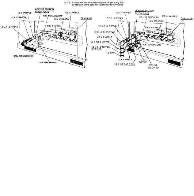
FIG. 3 - EXTERNAL SUPPLY CONNECTION |
FIG. 4 - BOTTOM SUPPLY CONNECTION |
EXTERNAL SHUT-OFF |
EXTERNAL SHUT-OFF |
|
|
The heating value of the gas may differ with locality. The value should be checked with the local gas utility.
NOTE: There may be a local gas utility requirement specifying a minimum diameter for gas piping. All units require a 1/2 inch pipe connection at the entrance fitting.
GAS CONNECTION
The gas supply line can be routed through the knockouts located on the front of the unit or through the opening provided in the unit’s base. Refer to Figure 9 to locate these access openings. Typical supply piping arrangements are shown in Figures 3 and 4. All shaded items are field-supplied.
Two grommets are shipped in the blower compartment (in parts bag taped to the blower housing) of every unit with gas heat and should be used in the knockouts when the gas piping penetrates the front of the unit.
After the gas supply piping has been installed, the bottom opening should be sealed to prevent water from leaking into the building.
Gas piping recommendations:
1.A drip leg and a ground joint union must be installed in the gas piping.
2.When required by local codes, a manual shut-off valve may have to be installed outside of the unit.
3.Use wrought iron or steel pipe for all gas lines. Pipe compound should be applied sparingly to male threads only.
WARNING: Natural gas may contain some propane. Propane, being an excellent solvent, will quickly dissolve white lead or most standard commercial compounds. Therefore, a special pipe compound must be applied when wrought iron or steel pipe is used. Shellac base compounds such as Gaskolac or Stalastic, and compounds such as Rectorseal #5, Cyde’s or John Crane may be used.
4.All piping should be cleaned of dirt and scale by hammering on the outside of the pipe and blowing out the loose dirt and scale. Before initial start-up, be sure that all of the gas lines external to the unit have been purged of air.
5.The gas supply should be a separate line and installed in accordance with all safety codes as prescribed under “Limitations”. After the gas connections have been completed, open the main shut-off valve admitting normal gas pressure to the mains. Check all joints for leaks with soap solution or other material suitable for the purpose. NEVER USE A FLAME.
6.The furnace and its individual manual shut-off valve must be disconnected from the gas supply piping system during any pressure testing of that system at test pressures in excess of 1/2 psig (3.48kPa).
The furnace must be isolated from the gas supply piping system by closing its individual manual shut-off valve during any pressure testing of the gas supply piping system at test pressures equal to or less than 1/2 psig (3.48kPa).
7.A 1/8 inch NPT plugged tapping, accessible for test gage connection, must be installed immediately upstream of the gas supply connection to the furnace.
L.P./PROPANE UNITS, TANKS AND PIPING
All gas heat units are shipped from the factory equipped for natural gas use only. The unit may be converted in the field for use with L.P./propane gas with accessory kit model number 1NP0440.
All L.P./propane gas equipment must conform to the safety standards of the National Fire Protection Association.
For satisfactory operation, L.P./propane gas pressure must be 10.5 inch W.C at the unit under full load. Maintaining proper gas pressure depends on three main factors:
1.The vaporization rate which depends on (a) the temperature of the liquid and (b) the “wetted surface” area of the container or containers.
2.The proper pressure regulation. (Two-stage regulation is recommended from the standpoint of both cost and efficiency.)
3.The pressure drop in the lines between regulators and between the second stage regulator and the appliance. Pipe size required will depend on the length of the pipe run and the total load of all appliances.
Complete information regarding tank sizing for vaporization, recommended regulator settings, and pipe sizing is available from most regulator manufacturers and L.P./propane gas suppliers.
L.P./propane gas is an excellent solvent and special pipe compound must be used when assembling piping for this gas as it will quickly dissolve white lead or most standard commercial compounds. Shellac base compounds such as Rectorseal #5 are satisfactory for this type of gas.
Check all connections for leaks when piping is completed, using a soap solution. NEVER USE A FLAME.
LOW NOx APPLICATION
For natural gas heat installations in locations which require low Nitros Oxide emissions, accessory model 1LN0404 must be installed.
6 |
Unitary Products Group |
 Loading...