


SAMPLING UNIT
Owner's Manual

IMPORTANT SAFETY INSTRUCTIONS
INFORMATION RELATING TO PERSONAL INJURY, ELECTRICAL SHOCK, AND FIRE HAZARD POSSIBILITIES HAS BEEN INCLUDED IN THIS LIST.
WARNING- When using any electrical or electronic product, basic precautions should always be followed. These precautions include, but are not limited to, the following:
1. Read all Safety Instructions, Installation Instructions, Special Message Section items, and any Assembly Instructions found in this manual BEFORE making any connections, including connection to the main supply.
2. Main Power Supply Verification: Yamaha products are manufactured specifically for the supply voltage in the area where they are to be sold. If you should move, or if any doubt exists about the supply voltage in your area, please contact your dealer for supply voltage verification and (if applicable) instructions. The required supply voltage is printed on the name plate. For name plate location, please refer to the graphic found in the Special Message Section of this manual.
3. This product may be equipped with a polarized plug (one blade wider than the other). If you are unable to insert the plug into the outlet, turn the plug over and try again. If the problem persists, contact an electrician to have the obsolete outlet replaced. Do NOT defeat the safety purpose of the plug.
4. Some electronic products utilize external power supplies or adapters. Do NOT connect this type of product to any power supply or adapter other than one described in the owners manual, on the name plate, or specifically recommended by Yamaha.
5. WARNING: Do not place this product or any other objects on the power cord or place it in a position where anyone could walk on, trip over, or roll anything over power or connecting cords of any kind. The use of an extension cord is not recommended! If you must use an extension cord, the minimum wire size for a 25' cord (or less) is 18 AWG. NOTE: The smaller the AWG number, the larger the current handling capacity. For longer extension cords, consult a local electrician.
6. Ventilation: Electronic products, unless specifically designed for enclosed installations, should be placed in locations that do not interfere with proper ventilation. If instructions for enclosed installations are not provided, it must be assumed that unobstructed ventilation is required.
7. Temperature considerations: Electronic products should be installed in locations that do not significantly contribute to their operating temperature. Placement of this product close to heat sources such as; radiators, heat registers and other devices that produce heat should be avoided.
8. This product was NOT designed for use in wet/damp locations and should not be used near water or exposed to rain. Examples of wet/damp locations are; near a swimming pool, spa, tub, sink, or wet basement.
9. This product should be used only with the components supplied or; a cart, rack, or stand that is recommended by the manufacturer. If a cart, rack, or stand is used, please observe all safety markings and instructions that accompany the accessory product.
10. The power supply cord (plug) should be disconnected from the outlet when electronic products are to be left unused for extended periods of time. Cords should also be disconnected when there is a high probability of lightening and/or electrical storm activity.
11. Care should be taken that objects do not fall and liquids are not spilled into the enclosure through any openings that may exist.
12. Electrical/electronic products should be serviced by a qualified service person when:
a.The power supply cord has been damaged; or
b.Objects have fallen, been inserted, or liquids have been spilled into the enclosure through openings; or
c.The product has been exposed to rain: or
d.The product dose not operate, exhibits a marked change in performance; or
e.The product has been dropped, or the enclosure of the product has been damaged.
13.Do not attempt to service this product beyond that described in the user-maintenance instructions. All other servicing should be referred to qualified service personnel.
14.This product, either alone or in combination with an amplifier and headphones or speaker/s, may be capable of producing sound levels that could cause permanent hearing loss. DO NOT operate for a long period of time at a high volume level or at a level that is uncomfortable. If you experience any hearing loss or ringing in the ears, you should consult an audiologist. IMPORTANT: The louder the sound, the shorter the time period before damage occurs.
15.Some Yamaha products may have benches and/or accessory mounting fixtures that are either supplied as a part of the product or as optional accessories. Some of these items are designed to be dealer assembled or installed. Please make sure that benches are stable and any optional fixtures (where applicable) are well secured BEFORE using. Benches supplied by Yamaha are designed for seating only. No other uses are recommended.
PLEASE KEEP THIS MANUAL
92-469-2

SPECIAL MESSAGE SECTION
PRODUCT SAFETY MARKINGS: Yamaha electronic products may have either labels similar to the graphics shown below or molded/stamped facsimiles of these graphics on the enclosure. The explanation of these graphics appears on this page. Please observe all cautions indicated on this page and those indicated in the safety instruction section.
CAUTION |
RISK OF ELECTRIC SHOCK |
DO NOT OPEN |
CAUTION: TO REDUCE THE RISK OF ELECTRIC SHOCK. |
DO NOT REMOVE COVER (OR BACK). |
NO USER-SERVICEABLE PARTS INSIDE. |
REFER SERVICING TO QUALIFIED SERVICE PERSONNEL. |
The exclamation point within the equilateral triangle is intended to alert the user to the presence of important operating and maintenance (servicing) instructions in the literature accompanying the product.
The lightning flash with arrowhead symbol, within the equilateral triangle, is intended to alert the user to the presence of uninsulated “dangerous voltage” within the product’s enclosure that may be of sufficient magnitude to constitute a risk of electrical shock.
IMPORTANT NOTICE: All Yamaha electronic products are tested and approved by an independent safety testing laboratory in order that you may be sure that when it is properly installed and used in its normal and customary manner, all foreseeable risks have been eliminated. DO NOT modify this unit or commission others to do so unless specifically authorized by Yamaha. Product performance and/or safety standards may be diminished. Claims filed under the expressed warranty may be denied if the unit is/has been modified. Implied warranties may also be affected.
SPECIFICATIONS SUBJECT TO CHANGE: The information contained in this manual is believed to be correct at the time of printing. However, Yamaha reserves the right to change or modify any of the specifications without notice or obligation to update existing units.
92-469- (rear)
ENVIRONMENTAL ISSUES: Yamaha strives to produce products that are both user safe and environmentally friendly. We sincerely believe that our products and the production methods used to produce them, meet these goals. In keeping with both the letter and the spirit of the law, we want you to be aware of the following:
Battery Notice: This product MAY contain a small non-rechargable battery which (if applicable) is soldered in place. The average life span of this type of battery is approximately five years. When replacement becomes necessary, contact a qualified service representative to perform the replacement.
Warning: Do not attempt to recharge, disassemble, or incinerate this type of battery. Keep all batteries away from children. Dispose of used batteries promptly and as regulated by applicable laws. Note: In some areas, the servicer is required by law to return the defective parts. However, you do have the option of having the servicer dispose of these parts for you.
Disposal Notice: Should this product become damaged beyond repair, or for some reason its useful life is considered to be at an end, please observe all local, state, and federal regulations that relate to the disposal of products that contain lead, batteries, plastics, etc.
NOTICE: Service charges incurred due to lack of knowledge relating to how a function or effect works (when the unit is operating as designed) are not covered by the manufacturer’s warranty, and are therefore the owners responsibility. Please study this manual carefully and consult your dealer before requesting service.
NAME PLATE LOCATION: The graphic below indicates the location of the name plate. The model number, serial number, power requirements, etc., are located on this plate. You should record the model number, serial number, and the date of purchase in the spaces provided below and retain this manual as a permanent record of your purchase.
Model _____________________________________
Serial No. __________________________________
Purchase Date ______________________________
PRECAUTIONS
PLEASE READ CAREFULLY BEFORE PROCEEDING
* Please keep these precautions in a safe place for future reference.
 WARNING
Always follow the basic precautions listed below to avoid the possibility of serious injury or even death from electrical shock, short-circuiting, damages, fire or other hazards. These precautions include, but are not limited to, the following:
•This instrument contains no user-serviceable parts. Do not attempt to disassemble or modify the internal components in any way.
•Do not expose the instrument to rain, use it near water or in damp or wet conditions, or place containers on it containing liquids which might spill into any openings.
•If the power cord or plug becomes frayed or damaged, or if there is a sudden loss of sound during use of the instrument, or if any unusual smells or smoke should appear to be caused by it, immediately turn off the power switch, disconnect the electric plug from the outlet, and have the instrument inspected by qualified Yamaha service personnel.
•Only use the voltage specified as correct for the instrument. The required voltage is printed on the name plate of the instrument.
•Before cleaning the instrument, always remove the electric plug from the outlet. Never insert or remove an electric plug with wet hands.
•Check the electric plug periodically and remove any dirt or dust which may have accumulated on it.
 CAUTION
Always follow the basic precautions listed below to avoid the possibility of physical injury to you or others, or damage to the instrument or other property. These precautions include, but are not limited to, the following:
•Do not place the power cord near heat sources such as heaters or radiators, and do not excessively bend or otherwise damage the cord, place heavy objects on it, or place it in a position where anyone could walk on, trip over, or roll anything over it.
•When removing the electric plug from the instrument or an outlet, always hold the plug itself and not the cord. Pulling by the cord can damage it.
•Do not connect the instrument to an electrical outlet using a multipleconnector. Doing so can result in lower sound quality, or possibly cause overheating in the outlet.
•Remove the electric plug from the outlet when the instrument is not to be used for extended periods of time, or during electrical storms.
•Before connecting the instrument to other electronic components, turn off the power for all components. Before turning the power on or off for all components, set all volume levels to minimum.
•Do not expose the instrument to excessive dust or vibrations, or extreme cold or heat (such as in direct sunlight, near a heater, or in a car during the day) to prevent the possibility of panel disfiguration or damage to the internal components.
•Do not use the instrument near other electrical products such as televisions, radios, or speakers, since this might cause interference which can affect proper operation of the other products.
•Do not place the instrument in an unstable position where it might accidentally fall over.
•Before moving the instrument, remove all connected cables.
•When cleaning the instrument, use a soft, dry cloth. Do not use paint thinners, solvents, cleaning fluids, or chemical-impregnated wiping cloths. Also, do not place vinyl, plastic or rubber objects on the instrument, since this might discolor the panel or keyboard.
•Do not rest your weight on, or place heavy objects on the instrument, and do not use excessive force on the buttons, switches or connectors.
•Do not operate the instrument for a long period of time at a high or uncomfortable volume level, since this can cause permanent hearing loss. If you experience any hearing loss or ringing in the ears, consult a physician.
■SAVING USER DATA
•Always save data to a floppy disk frequently, in order to help prevent the loss of important data due to a malfunction or user operating error.
Yamaha cannot be held responsible for damage caused by improper use or modifications to the instrument, or data that is lost or destroyed.
Always turn the power off when the instrument is not in use.


 Intro Yamaha SU700 Sampling Unit
Owner’s Manual
Thank you for your purchase of the Yamaha SU700 sampling unit. The SU700 is a combination sampler, sequencer, mixer, and multi-effector— a powerful new tool for a wide range of performance and recording environments.
This manual will help you learn what you need to know to make effective use of all of the SU700’s many features. Please read through the essential parts of the manual carefully before beginning work with the SU700, and refer back to the manual for additional information as necessary. Please keep the manual in a safe and handy location so that you can refer to it as necessary.
Intro |
5 |
INTRO

Intro
Features
The SU700 is an ideal tool for artists in need of sampling and sequencing capabilities for their recording and performance work. Here is just an abbreviated list of what’s included.
Forty-two tracks. With 40 sample tracks plus 2 special tracks, you can make your songs as complex as you wish.
Three different sample track types. LOOP tracks that generate automatic continuous loops; COMPOSED LOOP tracks that let you build your own custom loop phrases; and FREE tracks that are ideal for adding fills and playing along in real time.
AUDIO IN track lets you mix realtime vocals into your songs. You can control the sound of the realtime audio using both the knob functions and the effects.
Intuitive, playable controls. Use pads and knobs to control an astonishing number of functions on each track. You can record all control actions as sequence data, or you can apply controls on the fly during realtime performance. Special ribbon controller can be set to “scratch out” samples, or can be set to control level, pitch, or virtually any other parameter.
Powerful sampling capability. Provides high-quality sampling at any of five different sampling frequencies.
Triple-block effect system applies up to three effects at any given time. Select from a total of 43 great-sounding Yamaha effects. Set effect parameters for the effect itself, for the effect block, and for each track.
Scene memory stores up to eight scenes. Each scene holds an entire set of knob settings, mute settings, and effects. You can recall scenes instantly during performance, and you can record scene changes directly into your song.
Ample MIDI support. Use an external sequencer to control and synchronize SU700 track play; or use the SU700 to control playback from an external tone generator.
Easily expandable. Supports up to 64MB of expansion memory. Optional SCSI board (ASIB1) enables connection to external SCSI storage device. Optional I/O expansion board (AIEB1) adds digital and optical input/out and six assignable analog outputs.
Colorful, easy-to-read fluorescent display gives you all the feedback you need to maintain full control of the SU700’s power.
6 |
Intro |

Accessories
Please check your SU700 package to confirm that all of the following accessories are present. If any items are missing or damaged, please contact your Yamaha dealer for assistance.
●Sampling CD “SU700 Sampling Audio”
●Demo floppy disk
●Power cord
●This Owner’s Manual
●Flat 40-pin cable and round 3-pin cable (for use with optional AIEB1 board)
Using the Manual
Recommended Approach
Before switching on the machine you should read though Chapter 1 to familiarize yourself with the SU700 arrangement, and the usage of each of the SU700 controls and connectors. You may then want to jump into the comprehensive tutorial provided in Chapter 2, or instead read Chapters 3 and 4 first to familiarize yourself with the underlying concepts of SU700 operation. Refer also to Chapter 5 for details about samples and sampling.
Chapters 6 to 10 and various appendixes offer detailed reference information, and should be referred to as necessary.
Chapter Arrangement
■Chapter 1: SU700 Components, Connections, And Start-Up
Explains all of the SU700 controls and connectors, and shows you how to connect up and start the SU700. Please read through this chapter before you begin working the SU700.
■Chapter 2: Tutorial
Takes you through a comprehensive tutorial, showing you step-by-step how to build a complex song using samples provided on the accessory CD. Working through the tutorial will help you gain rapid mastery of SU700 operation.
Intro |
7 |
INTRO

Intro
■Chapter 3: Basic Concepts, Track Types, and Memory
Introduces basic concepts underlying SU700 operation. Also provides a detailed explanation of the different track types, and explains how the SU700 memory is organized. You should read through this chapter before you begin serious work with the SU700.
■Chapter 4: SU700 Operating Modes
Describes the six operating modes. Shows you how you can immediately identify the current mode by looking at the screen display; explains how you move from one mode to another; and indicates the operations that are and are not available from each mode.
■Chapter 5: Samples and Sampling
Explains samples, sampling, and the various sampling parameters. Provides detailed procedures for recording samples onto the SU700.
■Chapter 6: Using the Features
Offers detailed, reference-level explanations about how to use each of the SU700’s song-related features. Describes pad usage, knob usage, ribbon usage, scenes, markers, quantizing, and more.
■Chapter 7: Effects
Gives a detailed explanation of the SU700’s effects implementation. Describes the relation between tracks, effects, and the three effect blocks; explains how to set up the effects and record your setups into scenes; and explains the difference between system effects and insertion effects.
■Chapter 8: Knob Functions
Gives detailed information about the 22 parameters controlled by the track knobs.
■Chapter 9: Editing Functions
Describes the functions provided by the SU700’s Editing Function panel. You use these features to clear or set up the effects, to delete note events, to reset knob settings to their defaults, and to assist in name-editing.
■Chapter 10: Jobs
Provides detailed explanations and procedures for all of the SU700 jobs. You use these jobs for a wide variety of purposes—to configure your system, to save and load data, to edit or delete song data, to set the track characteristics, and much more.
8 |
Intro |

■Appendixes
Appendix 1 provides detailed instructions for installing each of the SU700’s supported options. Appendix 2 gives the SU700 specifications. Appendix 3 offers a number of helpful usage tips. Appendix 4 explains the SU700 error messages. Appendix 5 lists and describes the 43 built-in effects and their associated parameters. Appendix 6 explains the MIDI implementation.
Notations
This manual employs the following notational conventions.
●Button names are capitalized printed in uppercase bold and enclosed in brackets.
Examples: [CANCEL] and [OK].
●Words that appear directly on the screen are printed in a distinctive font.
Examples: SONG01 and SELECT TRACK.
●Jobs are identified by the job-group selector and job selector that you must press to access them. The group-selector appears first, followed by a bar, followed by the job selector.
Examples: SONG | NAME and RESAMPLE | TRACK
In cases where you must then select from multiple jobs by turning the dial, the job name is appended as shown below.
Example: SAMPLE | PROCESS/TRIM
●Buttons on the Knob Function panel and Editing Function panel are indicated by the group name, then a slash, then the button name.
Examples: SOUND/[LEVEL] and NAME/[INSERT]
●SU700 operating modes are written in uppercase. Examples: REC STANDBY and PLAY
●The following icons and symbols are also used.
NOTE. Indicates reference information indirectly related to the content of the main text. May contain practical advice or general supplementary information.
Procedure. Step-by-step instructions for carrying out a particular operation. Note that a ▼ mark within a procedure indicates the result produced by carrying out the immediately preceding instruction.
→number Page reference. Directs to another page for related information.
Intro |
9 |
INTRO

Intro
Finally, please note that screen illustrations and other drawings presented in this manual are for explanatory purposes only, and in some cases may differ from actual displays and configurations.
10 |
Intro |
Table of Contents
Intro |
Yamaha SU700 Sampling Unit Owner’s Manual |
|
|
|
Features ............................................................................................................. |
6 |
|
|
Accessories ........................................................................................................ |
7 |
|
|
Using the Manual .............................................................................................. |
7 |
|
|
Notations ........................................................................................................... |
9 |
|
Chapter 1 SU700 Components, Connections, and Startup |
|
||
|
1.1 |
SU700 Layout ........................................................................................ |
14 |
|
1.2 |
SU700 Display Configuration............................................................... |
23 |
|
1.3 |
Connecting Up....................................................................................... |
29 |
|
1.4 |
Starting Up ............................................................................................ |
33 |
Chapter 2 |
Tutorial |
|
|
|
2.1 |
Setting Up .............................................................................................. |
36 |
|
2.2 |
Listening to the Demo Song ................................................................. |
37 |
|
2.3 |
Building Your Own Song ...................................................................... |
47 |
|
2.4 |
Modifying sampled sounds................................................................... |
95 |
Chapter 3 Basic Concepts, Track Types, and Memory |
|
||
|
3.1 |
Basics ................................................................................................... |
132 |
|
3.2 |
Sample-Track Types ............................................................................ |
135 |
|
3.3 |
Memory Implementation.................................................................... |
137 |
Chapter 4 SU700 Operating Modes |
|
||
|
4.1 |
Introduction ........................................................................................ |
140 |
|
4.2 |
Sequencer Modes ................................................................................ |
141 |
|
4.3 |
Other Modes ........................................................................................ |
146 |
Chapter 5 Samples and Sampling |
|
||
|
5.1 |
All about Samples ............................................................................... |
150 |
|
5.2 |
Sample Recording Procedure............................................................. |
156 |
Chapter 6 Using the Features |
|
||
Chapter 7 |
Effects |
|
|
|
7.1 |
Introduction ........................................................................................ |
186 |
|
7.2 |
Using the Effects ................................................................................. |
186 |
|
7.3 |
Effect Blocks ....................................................................................... |
188 |
|
7.4 |
System Effects ..................................................................................... |
189 |
|
7.5 |
Insertion Effects .................................................................................. |
190 |
|
7.6 |
Usage Tips............................................................................................ |
191 |
|
7.7 |
Changing the Effect Resolution ......................................................... |
192 |
Table of Contents |
11 |
TABLE OF CONTENTS

Table of Contents
Chapter 8 Knob Functions |
|
|
8.1 |
Overview .............................................................................................. |
194 |
8.2 |
Knob Settings for Each Track ............................................................ |
195 |
8.3 |
Quantize and Resolution .................................................................... |
196 |
8.4 |
Parameter Descriptions ...................................................................... |
197 |
Chapter 9 Editing Functions
9.1 |
Overview .............................................................................................. |
214 |
9.2 |
EFFECT SETUP Group ...................................................................... |
214 |
9.3 |
JOB Group ........................................................................................... |
220 |
9.4 |
NAME Group ...................................................................................... |
221 |
Chapter 10 Jobs
10.1 |
Overview and Job List......................................................................... |
224 |
10.2 |
General Procedure .............................................................................. |
225 |
10.3 |
Job Explanations................................................................................. |
227 |
Appendix
Installing the Options ................................................................................... |
312 |
Specifications ................................................................................................ |
326 |
SU700 Usage Hints ....................................................................................... |
328 |
Error Messages ............................................................................................. |
331 |
Effect Type List ............................................................................................. |
333 |
Effect Parameter List .................................................................................... |
335 |
MIDI Data Format ........................................................................................ |
345 |
MIDI Implementation Chart ........................................................................ |
348 |
12 |
Table of Contents |


 Chapter 1 SU700 Components,
Connections, and Startup
This chapter describes the SU700’s layout and screen displays, shows you how you can connect the SU700 to other devices, and takes you through the SU700 startup procedure.
CONTENTS
1.1 |
SU700 Layout |
14 |
1.2 |
SU700 Display Configuration |
23 |
1.3 |
Connecting Up |
29 |
1.4 |
Starting Up |
33 |
Chapter 1 SU700 Components, Connections, and Startup |
13 |
CHAPTER 1

Chapter 1 SU700 Components, Connections, and Startup
1.1 SU700 Layout
This section explains all of the SU700 components.
1.1.1 Main Panel |
|
|
|
|
|
N |
M |
L |
K J |
H |
I |
|
|
|
|
|
G |
|
|
|
|
|
F |
O |
|
|
|
|
|
|
|
|
|
|
E |
|
|
|
|
|
D |
|
|
|
|
|
C |
|
|
|
|
|
B |
|
|
|
|
|
A |
P |
|
1 |
|
|
0 |
|
|
|
|
|
|
|
|
|
|
|
9 |
|
|
|
|
|
8 |
|
|
|
|
|
7 |
|
|
|
|
|
|
|
|
|
|
|
|
|
|
|
|
|
|
|
|
|
|
|
|
|
|
|
|
|
|
|
|
|
|
|
|
|
|
|
|
|
|
|
|
|
|
|
|
|
|
|
|
|
|
|
|
|
|
|
|
|
|
|
|
|
|
|
|
|
|
|
|
|
|
|
|
|
|
|
|
|
|
|
|
|
|
|
|
|
|
|
|
|
|
|
|
|
|
|
|
|
|
|
|
|
|
|
|
|
|
|
|
|
|
|
|
|
|
|
|
|
|
|
|
|
|
|
|
|
|
|
|
|
|
|
|
|
|
|
|
|
|
|
|
|
|
|
|
|
|
|
|
|
|
|
|
|
|
|
|
|
|
|
|
|
|
|
|
|
|
|
|
|
|
|
|
|
|
|
|
|
|
|
|
|
|
|
|
|
|
|
|
|
|
|
|
|
|
|
|
|
|
|
|
|
|
|
|
|
|
|
|
|
|
|
|
|
|
|
|
|
|
|
|
|
|
|
|
|
|
|
2 |
|
|
3 |
4 |
5 |
6 |
|||||||||||||||
1Display
The display provides all the information you need to work effectively at the SU700. For a detailed explanation of common screen displays and indications, see page 23.
14 |
Chapter 1 SU700 Components, Connections, and Startup |

2TRACK BANK Selectors
You use the track bank selectors in combination with the sample track pads to select tracks for playback, recording, editing, and control.
The SU700 provides four track banks, each with ten sample tracks. This gives you a total of 40 sample tracks. This means that each song can utilize anywhere from 1 to 40 samples.
3Sample Track Pads
You use these 10 pads to control play on the sample tracks, and to select tracks for sample recording, track editing, and track setup.
Each pad can be used to control a variety of operations. At any given time, each pad controls a single operation only. You can switch the pad operation using the PAD FUNCTION selectors (see item 5 below).
The pads for COMPOSED LOOP and FREE tracks include velocity sensors that are effective for PLAY and LOOP RESTART pad functions. (→ p.167, 301)
4AUDIO IN Track Pad
You use this pad to set or release the mute for the AUDIO IN track, or to select the AUDIO IN track during setup work.
5MASTER Track Pad
Use this pad to set or release the mute on all other tracks, to restart looping on the LOOP and COMPOSED LOOP tracks, or to select the MASTER track during setup work.
6PAD FUNCTION Selectors
The pad function selectors select the operation to be controlled by the pad.
Each track has a default pad function that is effective whenever you are working
at the main screen. You can set these defaults using the TRACK SET | MAIN job (→ p. 231).
You can override the defaults by pressing any of these selectors during song recording, playback, or standby. This will switch you to a function screen and will cause all pads to switch to the selected function.
For detailed information about pad functions and their selection, see page 166. For information about the difference between the main screen and the function screens, see page 144.
Chapter 1 SU700 Components, Connections, and Startup |
15 |
CHAPTER 1

Chapter 1 SU700 Components, Connections, and Startup
7Knobs
You use these knobs to control the values of multiple parameters (or knob settings) on each track. At any given time each knob controls a single parameter only. You use the KNOB FUNCTION panel (see item 9 below) to switch the parameter controlled by the knobs.
When you are working the main screen, each knob controls its default parameter.
You can set these default separately for each track using the TRACK SET | MAIN job (→ p.231).
8[RIBBON TRACK] Button
You use this button when you want to change the track(s) controlled by the ribbon. You select the track(s) by holding down the button and pressing the appropriate pad.
If you press the pad for a sample track, then the ribbon will work on all four tracks associated with that pad (the tracks in Banks 1, 2, 3, and 4 for that pad). If you press the pad for the AUDIO IN or MASTER track, then the ribbon will operate on that track only.
9 NOTE Display and Button
The bottom right corner of the display indicates relevant Quantize or Resolution interval. If necessary, you can adjust the setting by pressing the [NOTE] button (so that the indication starts blinking) and then turning the dial. Intervals are indicated using note images (  , , etc.).
Exception: To set the resolution for the ROLL pad function, you must first press the [NOTE] button, and then hold down the [ROLL] button while turning the dial.
0BPM Display and Button
The center right line of the screen indicates the song’s current tempo, in BPM (beats per minute). You can change the tempo by pressing the [BPM] button (so that the BPM indication starts blinking) and then turning the dial.
A MEASURE Display and Button
The top right corner of the screen indicates the current song location, by measure and beat. One way to change the location is to use the 

 ,
, 

 , and
, and 

 buttons, as described above. Another way is to press the [MEASURE] button (so that the measure indication starts blinking) and then turn the dial.
BRibbon Controller
You can set the ribbon up to control a single selected function with respect to a single pad. You select the track set using the [RIBBON TRACK] button; see below.
16 |
Chapter 1 SU700 Components, Connections, and Startup |

Once you have set this up, you can rub your finger along the ribbon to control the selected function on the corresponding track. For example, if you set the function to LEVEL then you use the ribbon to adjust the level on the track.
Available functions include most of the knob functions, and a special scratch function that lets you scratch out the sound of a selected track—the same kind of sound that you would get by manually turning a vinyl record forward or backward. For more information about ribbon use, see page 172.
C[CANCEL] and [OK] Buttons
Use these buttons to confirm or cancel various operations, or to move forward or backward through the various job screens. Actual operation varies according to the SU700’s current state.
DDial
Use this dial to enter and adjust various values. Actual operation varies according to the SU700’s current state. The value that can be adjusted by the dial is usually shown in blinking format on the display.
E[BPM COUNTER] button
This button makes it easy to set the tempo to match the tempo of external playback that you may be preparing to record or play along with. To get a tempo reading, simply tap on the counter along with the beat (hitting the counter once at each beat). The SU700 detects a BPM value from your taps, and flashes this value in the BPM area on the screen. If you wish to keep the new tempo, press [OK]. (If you do not press [OK], the SU700 will restore the previous setting.)
FCursor Buttons ( and
and  )
)
Use these buttons to move the cursor position when editing names on the screen, or to move from one parameter to another when working at setup screens containing multiple parameters.
GMASTER VOLUME Knob
Turn the knob to adjust the output level to the STEREO OUT jacks. Note that this adjustment does not affect the output level to any of the outputs on the optional AIEB1 board.
HSAMPLING: STANDBY/START/STOP Button ([SAMPLING] button)
Use this button to begin and end sample recording. For details about how to record samples, see the explanation beginning on page 156.
ISAMPLING: ANALOG LEVEL Knob
Turn this knob to adjust the input level when recording a sample from analog input. The screen displays a level meter that will help you set an appropriate level.
Chapter 1 SU700 Components, Connections, and Startup |
17 |
CHAPTER 1

Chapter 1 SU700 Components, Connections, and Startup
J[UNDO/REDO] Button
You use this button to undo or redo all changes that you recorded into your song during your previous recording pass. This feature is useful for undoing poor results, or for comparing “before” and “after” versions to determine which you want
to keep. The [UNDO/REDO] button operates only while the sequencer is in PLAY STANDBY mode. (→ p.183)
KSequencer Controls
Use these buttons to control the sequencer. Button usage is outlined below. For detailed information, refer to “Using the Sequencer,” (→ p.162). Also refer to
Chapter 4, “SU700 Operating Modes,” for an overview of the different sequencer modes (→ p.139).


 RECORD
Press to enter recording standby.
TOP OF SONG
Press to jump back to the top of the song (first beat of first measure).
FAST REVERSE
Hold down to move rapidly backward through the song.
STOP
Press to stop song playback or recording.
PLAY
Press to start song playback or recording.
FAST FORWARD
Hold down to move rapidly forward through the song.
LJob Grid
You use these buttons to access various SU700 jobs. These jobs let you carry out a wide variety of editing, setup, and management tasks.
To select a job, you first press one of the job group selectors along the top of the grid, and then press one of the job selectors along the left of the grid. You can then carry out the job using the dial, cursor buttons, [CANCEL] or [OK] buttons, and any other relevant controls.
For detailed explanations of all jobs, refer to Chapter 10, “Jobs,” on page 223.
M[SCENE/MARKER] Buttons
Operation depends on whether you have selected [SCENE] or [MARKER] with the scene/marker switch.
If SCENE: The SU700 lets you store up to eight scenes per song. A scene is an entire environment of knob settings, mute settings, and effect settings. To store the current environment, hold down one of the scene buttons (from [TOP] to [G]) for approximately 1.5 seconds, until the screen says SCENE STORED. To recall a scene, press the corresponding scene button briefly.
18 |
Chapter 1 SU700 Components, Connections, and Startup |

If you store a scene into the [TOP] button, this scene will automatically be recalled when you return the song to its start position.
You can use the [INIT] scene button to initialize (clear) the content of any scene. Simply hold down the [INIT] button and then press the scene button that you want to initialize. (→ p.180)
Note that you can store and initialize scenes only while the sequencer is in PLAY or PLAY STANDBY mode. You can recall scenes at any time.
For more information about scenes, refer to page 176.
If MARKER: Use markers [1] to [8] to store song positions or to immediately jump the song to a stored position. These buttons only work while the sequencer is in PLAY or PLAY STANDBY mode.
To store the current position, hold down one of the marker buttons for about 1.5 seconds, until the screen says MARKER STORED. To jump to that position, press the same button briefly.
NSCENE/MARKER Switch
Use this switch to select the operating mode of the [SCENE/MARKER] buttons. Set the switch to the left if you want the buttons to control scenes; set to the right if you want the buttons to control markers.
OKNOB FUNCTION Panel
When you press one of these buttons during song standby, recording, or playback, the display automatically switches to the corresponding function screen, and all knobs automatically get control of the selected parameter. You can adjust the value on each track by turning the corresponding knob (and using the bank selectors as necessary to switch the bank).
You can also use these buttons to make selections within certain jobs; for example, to select the default knob functions for the TRACK SET | MAIN job.
For detailed information, refer to Chapter 8, page 193.
PEdit Function Panel
You can use these buttons to perform various tasks: to set up each of the three effect blocks, to switch off any of the effects, to reset knob settings on selected tracks, and to insert or delete characters within a name you are editing. For detailed information, see Chapter 9, page 213.
Chapter 1 SU700 Components, Connections, and Startup |
19 |
CHAPTER 1

Chapter 1 SU700 Components, Connections, and Startup
1.1.2 Front Panel
3 1 2 4
1Floppy-Drive Slot
The drive accepts 3.5" floppy disks (2HD or 2DD). You can use the disks to save and reload all data, and to import commercially available sample or voice data.
2Floppy Eject Button
Press this button to eject the floppy disk currently inserted in the slot. Remember: Do not eject the disk while the access lamp is lit.
3Floppy Access Lamp
This lamp lights up to indicate that the SU700 is currently accessing the disk.
 CAUTION
Do not press the EJECT button or switch off the power while this lamp is lit, as doing so may destroy data on the disk or cause damage to the disk drive.
4Headphone Jack
Connects to standard stereo headphones. Outputs the same signal as the stereo output jacks on the rear panel.
20 |
Chapter 1 SU700 Components, Connections, and Startup |
1.1.3 Rear Panel
6 |
7 |
8 |
9 |
OPTICAL |
DIGITAL |
|
|
|
ASSIGNABLE OUT |
|
SCSI |
||
|
|
|
|
|
|||||
IN |
OUT |
IN |
OUT |
AS6 |
AS5 |
AS4 |
AS3 |
AS2 |
AS1 |
|
|
|
|
|
|
|
|
||
|
|
|
|
|
|
|
MIDI |
|
|
|
|
|
|
|
|
OUT |
|
IN |
AC INLET |
|
|
|
|
|
|
|
|
|
|
STEREO OUT |
ANALOG INPUT |
|
|
|
|
|
CAUTION |
||
R |
L/MONO |
R |
L |
|
|
|
|
|
|
|
|
|
|
|
RISK OF ERECTRIC SHOCK |
||||
|
|
|
|
|
|
|
|
|
|
|
|
|
|
|
|
|
|
|
DO NOT OPEN |
|
|
|
|
|
|
|
|
ATTENTION :RISQUE DE CHOC ELECTRIQUE ME PAS OUVRIR. |
|
|
|
|
|
|
|
|
|
|
TO REDUCETHE RISK OF FIRE OR ERECTRIC SHOCK |
|
|
|
|
|
|
|
|
WARNING DO NOT EXPOSETHIS PRODUCTTO RAIN OR MOISTURE. |
|
POWER
 ON/
ON/ OFF
OFF
1 |
2 |
3 |
4 |
5 |
Circled numbers indicate standard connectors. Numbers enclosed in squares indicate options.
In its standard configuration, the rear panel provides connectors 1 to 5 above. If you install the optional AIEB1 board, you also get the assignable and digital outputs (items 7, 8, and, 9 above). If you install the optional ASIB1 board (SCSI board), you also get the SCSI connector (number 6 above).
Note that if an option board is not installed, the corresponding area of the panel is covered with an expansion cover.
1STEREO OUT Jacks
These jacks output the stereo analog signal produced by the SU700 to powered speakers or other playback device. (For monaural output, use the left jack only.)
These are the standard outputs.
2ANALOG INPUT Jacks
Standard analog input jacks accept line or microphone input. Use these jacks to input analog signals to be recorded (as samples) or fed to the AUDIO IN track (during realtime performance).
Note that you must use the SYSTEM | SETUP job to inform the system of the actual audio input you are using (→ p.298).
3MIDI Connectors
Standard MIDI connectors. Use these connectors to link the SU700 to other MIDI devices.
Chapter 1 SU700 Components, Connections, and Startup |
21 |
CHAPTER 1

Chapter 1 SU700 Components, Connections, and Startup
4AC Inlet
Connects to SU700 power cord.
 CAUTION
Use the supplied power cord only. Use of a different cord may result in electric shock or device damage.
5POWER Switch
Switches the SU700 power ON and OFF.
<If AEIB1 option board is installed> 6 OPTICAL IN/OUT connectors
7DIGITAL IN/OUT connectors
Use the OPTICAL connectors to input or output digital audio signals over opticalfiber cable. Use the DIGITAL connectors to input or output digital audio signals over coaxial (RCA-pin) cable, in CD/DAT (S/P DIF) format.
Each connector can support both mono and stereo signals.
Input Signal: The SU700 can accept input digital frequencies of 11.025kHz,
22.05kHz, 32.0kHz, 44.1kHz, and 48.0kHz. (If you wish to enable this input, you must open the SYSTEM | SETUP job and set AUDIO IN to either OPTICAL or DIGITAL. See page 302.)
Output Signal: The output frequency is always 44.1kHz. The output is the digital equivalent of the signal directed to the STEREO OUT jacks, but is not passed through the effects blocks. Note that the OPTICAL OUT and DIGITAL OUT connectors will always produce the identical signal.
8ASSIGNABLE analog output jacks
You can set the output destination independently for each nonempty sample track. Settings can be entered separately for each song. Note that these settings are not available for the AUDIO IN track, for the MASTER TRACK, and for sample tracks that do not currently contain a sample.
Under default conditions, output is directed to the STEREO OUT jacks (and OPTICAL and DIGITAL connectors). As an alternative, however, you can use the TRACK SET | SETUP job to direct the track’s output to any one of the assignable outputs (AS 1 to AS 6), or to an adjacent pair of outputs (AS 1+2, AS 3+4, or AS 5+6). Note that signals directed to assignable outputs do not pass through the effects blocks (do not receive any effects).
<If ASIB1 option board is installed>
9SCSI connector
A SCSI-2 D-sub half-pitch 50-pin connector that can be used to connect to an external SCSI disk device. Allows for convenient saving and loading of large quantities of data.
22 |
Chapter 1 SU700 Components, Connections, and Startup |
1.2 SU700 Display Configuration
You refer to the SU700 screen for information and guidance during all SU700 operations. This section presents an overview of the various screen displays.
The first part, “Screen Layout,” introduces the various elements of the display panel. The second part, “Main-Screen and Function-Screen Displays,” shows screen examples for the two most frequently used working environments. The third part, “Other Screen Indication,” gives an overview of less commonly encountered screen indications.
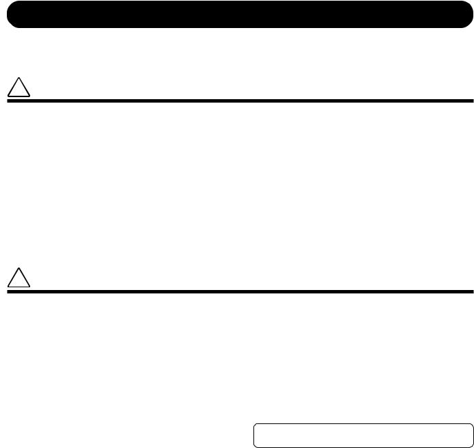
1.2.1 Screen Layout
The screen is divided into several different areas, each presenting a different type of information. The general arrangement is described below. The amount of information displayed at any given time will vary according to the operating mode and current conditions.
1 |
2 |
3 |
|
|
|
|
|
|
|
|
|
MEASURE |
6 |
|
4 |
7 |
|
BPM |
||
|
5 |
8 |
|
NOTE |
1 Bank ............................ |
Shows the currently selected bank. Always displayed. |
2 REC indicator ............ |
Comes on to indicate that the sequencer is in REC or REC |
|
STANDBY mode. |
3 Pad function .............. |
Shows the currently selected pad function. Displayed |
|
whenever you are working at a function screen. |
4 Parameter data.......... |
This area shows parameter information and error mes- |
|
sages. |
|
When you are at the main screen, this area shows the cur- |
|
rent song number and song name. When you are at a |
|
function screen, this area shows the current knob func- |
|
tion and the function value. When you are executing a |
|
job, this area shows the job type and/or current setting. |
|
Before you record a sample, you refer to this area to set |
|
the sampling parameters. |
CHAPTER 1
Chapter 1 SU700 Components, Connections, and Startup |
23 |

Chapter 1 SU700 Components, Connections, and Startup
5 Track indicator .......... |
When you are working at the main screen or a function |
|
screen, each vertical bar meter (or track meter) indicates |
|
the relevant knob-function value for the corresponding |
|
track (of the current bank). The brackets (above and be- |
|
low the meter) are visible if the track is not muted; they |
|
disappear if the track is muted. |
|
When you are standing by to record a sample, the meter |
|
area operates as a two-bar horizontal level meter that you |
|
can use to monitor the input level. The upper bar indi- |
|
cates the L-channel level; the lower bar indicates the R- |
|
channel level. |
6 MEASURE .................. |
Shows the current location (measure and beat) within the |
|
current song. |
7 BPM ............................. |
Shows the current tempo (in beats per minute). |
8 NOTE ........................... |
Shows the quantize interval or time resolution, when ap- |
|
plicable. |
24 |
Chapter 1 SU700 Components, Connections, and Startup |
1.2.2 Main-Screen and Function-Screen Displays
The screen display content varies according to the current machine state. This section shows screen displays for two most commonly used machine states.
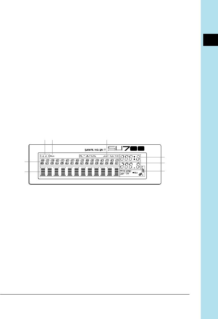
Main Screen
This screen that appears immediately following power-on. It is also the default screen, and will reappear when you exit from job mode, when you finish sample recording, and when you press [OK] to escape from a function screen.
Note that this screen can appear only while the sequencer is operating in PLAY STANDBY or PLAY mode. (→ p.142)
When you are working at this screen, the knob and pad action for each track is determined by the settings you make at the TRACK SET | MAIN job (→ p.231). This means that the knobs and pads on different tracks may operate in different ways.
1 |
4 |
|
|
2 |
|
|
5 |
|
6 |
|
3 |
1 Currently selected bank.
2Currently selected song number and name. (If the sequencer is in PLAY STANDBY, you can change to a different song by turning the dial and then pressing [OK].)
3Shows function values and muting for each track within the current bank.
•Note that all meters always indicate the value for the default knob parameter on the most recently controlled track (the track whose pad or knob you last touched). If you hit the pad on a track whose default knob-function is set to PITCH, for example, then all meters indicate PITCH levels. If you then hit a pad on another track whose default knob function is set to ATTACK, all meters change to indicate ATTACK levels.
•Brackets are visible if track is non-muted; invisible if track is muted.
4 Current position in song.
5 Tempo setting.
6 The NOTE area is always empty.
CHAPTER 1
Chapter 1 SU700 Components, Connections, and Startup |
25 |

Chapter 1 SU700 Components, Connections, and Startup
Function Screen
You enter this screen from the main screen when you press any knob-function or pad-function button, or when you press the [REC] button.
When you are working at a function screen, knob functions and pad functions are the same on all tracks.
A typical display appears as follows.
|
1 |
|
|
|
|
|
|
2 |
|
|
|
|
|
|
4 |
|
|
|
|
|
|
|
|
|
|||||||||||||
|
3 |
|
|
|
|
|
|
|
|
|
|
|
|
|
|
|
|
|
|
|
|
|
|
|
|
|
|
|
|
|
|
|
|
|
|
|
6 |
|
|
|
|
|
|
|
|
|
|
|
|
|
|
|
|
|
|
|
|
|
|
|
|
|
|
|
|
|
|
|
|
|
|
|
|
||
|
|
|
|
|
|
|
|
|
|
|
|
|
|
|
|
|
|
|
|
|
|
|
|
|
|
|
|
|
|
|
|
|
|
|
|
||
|
|
|
|
|
|
|
|
|
|
|
|
|
|
|
|
|
|
|
|
|
|
|
|
|
|
|
|
|
|
|
|
|
|
|
|
||
|
|
|
|
|
|
|
|
|
|
|
|
|
|
|
|
|
|
|
|
|
|
|
|
|
|
|
|
|
|
|
|
|
|
|
|
||
|
|
|
|
|
|
|
|
|
|
|
|
|
|
|
|
|
|
|
|
|
|
|
|
|
|
|
|
|
|
|
|
|
|
|
|
||
|
|
|
|
|
|
|
|
|
|
|
|
|
|
|
|
|
|
|
|
|
|
|
|
|
|
|
|
|
|
|
|
|
|
|
|
||
|
|
|
|
|
|
|
|
|
|
|
|
|
|
|
|
|
|
|
|
|
|
|
|
|
|
|
|
|
|
|
|
|
|
|
|
|
|
|
|
|
|
|
|
|
|
|
|
|
|
|
|
|
|
|
|
|
|
|
|
|
|
|
|
|
|
|
|
|
|
|
|
|
|
|
|
|
|
|
|
|
|
|
|
|
|
|
|
|
|
|
|
|
|
|
|
|
|
|
|
|
|
|
|
|
|
|
|
|
|
|
|
|
|
|
|
|
|
|
|
|
|
|
|
|
|
|
|
|
|
|
|
|
|
|
|
|
|
|
|
|
|
|
|
|
|
|
|
|
|
|
|
|
|
|
|
|
|
|
|
|
|
|
|
|
|
|
|
|
|
|
|
|
|
|
|
|
|
|
|
|
|
|
|
|
|
|
|
||
|
|
|
|
|
|
|
|
|
|
|
|
|
|
|
|
|
|
|
|
|
|
|
|
|
|
|
|
|
|
|
|
|
|
|
|
||
|
|
|
|
|
|
|
|
|
|
|
|
|
|
5 |
|
|
|
|
|
|
|
|
|
|
|
|
|
|
|
|
|
|
|
|
|||
1 |
Appears only if you have pressed |
to set the sequencer into RECORD mode. |
|||||||||||||||||||||||||||||||||||
2 |
Indicates the current pad function. |
|
|
|
|
|
|
|
|
|
|
|
|
|
|
|
|
|
|
|
|
|
|
|
|
||||||||||||
3 |
Indicates the current knob function. |
|
|
|
|
|
|
|
|
|
|
|
|
|
|
|
|
|
|
|
|
|
|
|
|
||||||||||||
4 |
Indicates the knob-function value for the track whose pad or knob you last used. |
||||||||||||||||||||||||||||||||||||
5Each meter indicates the knob function’s value ( in this case, the PITCH value) for the corresponding track. The bracket is visible if the track is not muted; invisible if the track is muted.
6 Indicates the QUANTIZE or RESOLUTION setting, if applicable. (Does not appear for some knob functions.)
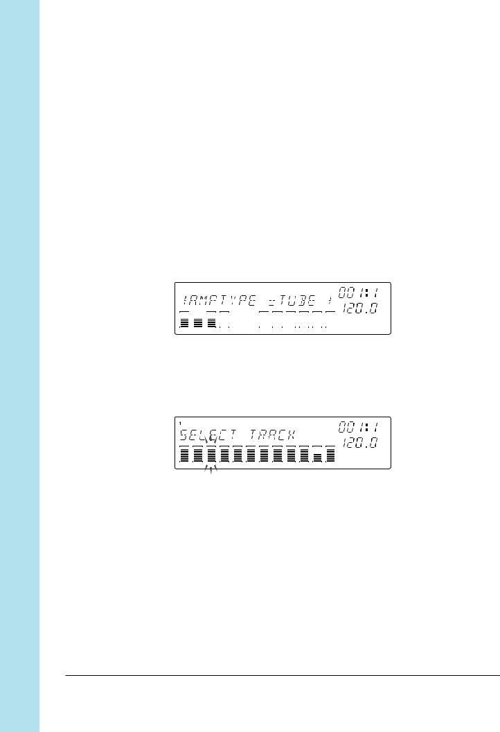
1.2.3Other Screen Indications
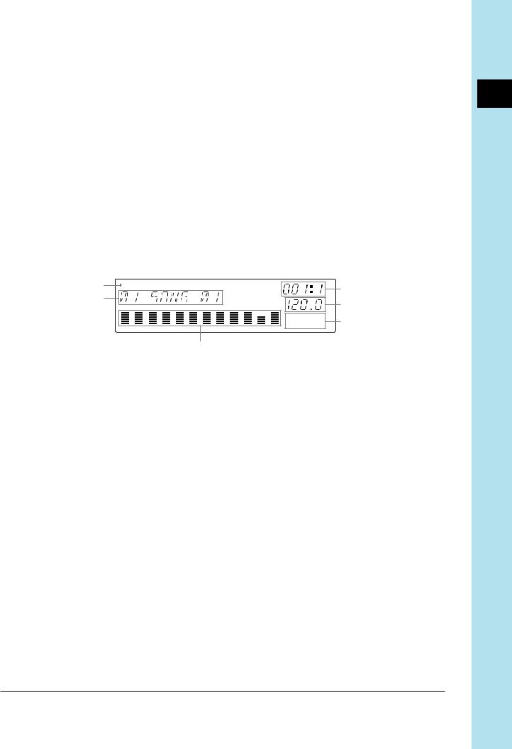
Track Selection
Before you can record a sample, you must select the target track. Many job screens will also require you to select a track.
To select a track, you press the appropriate bank selector and hit the appropriate track pad (in either order). The bank number will appear at the upper left of the screen, and brackets will move to indicate the selected track.
When you are making this type of a selection, the screen will also let you know whether or not the selected track contains a sample. If the track does contain a sample, then a double bar will appear at the center of the bracketed area. If the track is empty, then no bar will appear.
The following shows the display you use to select the track when preparing to record a sample.
26 |
Chapter 1 SU700 Components, Connections, and Startup |
Indicates that the selected track already contains a sample. If the track is empty, this bar will not appear.
NOTE:
For TRACK EDIT | EVENT COPY, TRACK EDIT | EVENT INIT etc., it is also important to know whether a selected track contains recorded sequence data. For these jobs, six bars will appear at the center of the bracketed area to indicate that the track contains both a sample and some sequence data.
Sample only: |
Sample plus sequence data: |
||||
|
|
|
|
|
|
|
|
|
|
|
|
|
|
|
|
|
|
|
|
|
|
|
|
|
|
|
|
|
|
|
|
|
|
|
|
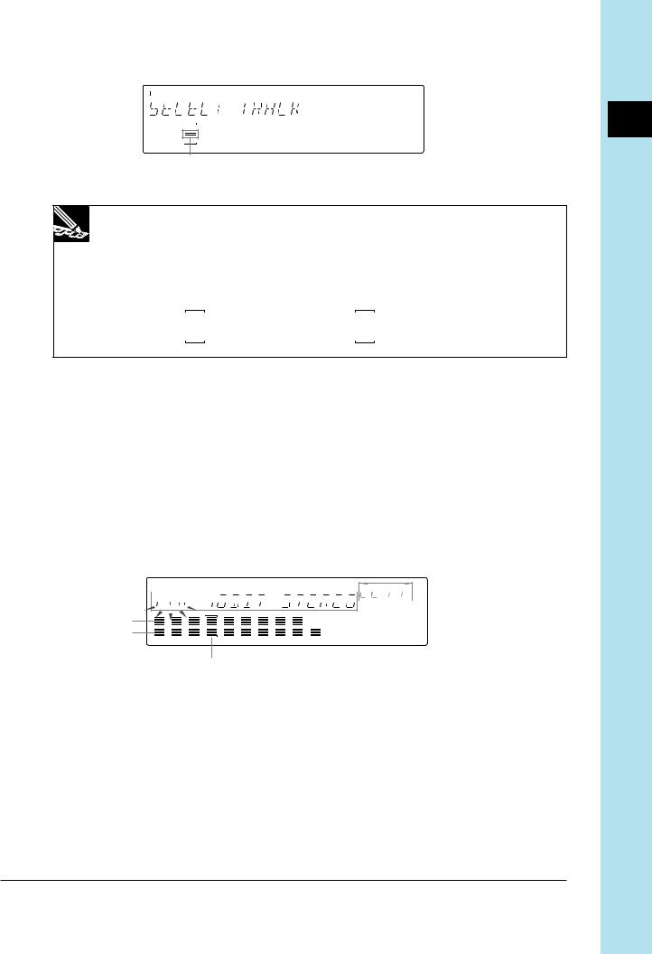
Sample Recording Meter
When you are standing by to record a sample (or to execute a resampling job), the meter operates as a two-bar horizontal level meter. The top part of the meter monitors the level for the LEFT channel input, while the bottom part of the meter monitors the level for the RIGHT channel input. In addition, the word CLIP will appear at the upper right of the screen if the input level exceeds the clip level.
In general, you want to adjust the input level so that the meter peaks all the way to the right without triggering the CLIP indication.
The following shows how the screen may appear when you are standing by to begin sample recording.


 5 1
5 1


2
3
4
1 Shows the recording parameters.
2 Monitors the left-channel input level.
3 Monitors the right-channel input level.
4 Shows the destination track.
5 CLIP indicator
CHAPTER 1
Chapter 1 SU700 Components, Connections, and Startup |
27 |
Chapter 1 SU700 Components, Connections, and Startup
Flashing Parameters
When you are working at a screen that allows you to set more than one parameter value, the parameter currently selected for setting will be blinking, indicating that you can proceed to change its value by turning the dial (or pressing an appropriate button). Note that only one parameter can be blinking at any given time.
In the screen illustration shown above, for example, the 44K value (frequency setting) is flashing. This tells you that turning the dial will change the frequency setting. If you wish to change one of the other parameters, then you would first need to press the  to move the flashing indication to either 16BIT or STEREO.
Multipage Displays
Some setup screens consist of multiple pages. A right-arrow in the display indicates that you can advance to another page by pressing the  cursor button; a left arrow means that you can move back to a previous page by pressing the
  button.
The following shows the third page of the AMPSIM-effect setup screen.
Ribbon-Track Indication
When you press the [RIBBON TRACK] button, the brackets for the currently selected ribbon track blink on the screen. You can change the selection by pressing a different pad. (→ p.172)
28 |
Chapter 1 SU700 Components, Connections, and Startup |

1.3 Connecting Up
The SU700 is extremely easy to set up. Simply connect the appropriate components as described below.
Power
Connect the power as follows.
1. Confirm that the power switch (on the rear panel) is in the OFF position (protruding from the panel). If the switch is ON, press it so that it pops out into the OFF position.
2. Connect the small end of the supplied power cable to the power inlet on the rear panel.
3. Connect the other end to a standard wall outlet.
 CAUTION
Do not connect the power while the power switch is ON.
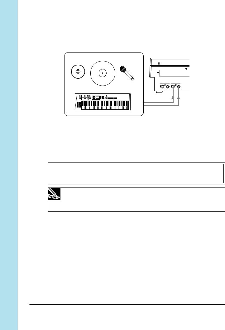
Input Source
If you are going to record a sample or supply an audio input signal to accompany realtime playback, you need to connect an input source. You can connect up one or more of the following.
●Connect a microphone to the one of the ANALOG INPUT jacks on the rear panel.
●Connect analog line input (for example, from a CD player or electronic instrument) to the ANALOG INPUT jacks on the rear panel. To input a stereo signal, connect to both jacks.
●(If you have installed the optional AIEB1 board:) Connect a digital or optical line to the DIGITAL IN or OPTICAL IN connector on the rear panel.
CHAPTER 1
Chapter 1 SU700 Components, Connections, and Startup |
29 |
Chapter 1 SU700 Components, Connections, and Startup
To enable input, you must set the AUDIO IN parameter to the source you wish to use. You can set the parameter using the SYSTEM | SETUP job; see page 302. The SU700 can only accept input from one source at a time.
CD |
Record (turntable) Microphone |
STEREO OUT |
ANALOG INPUT |
||
R |
L/MONO |
R |
L |
Electric keyboard |
|
|
|
Output
You can connect any or all of the following.
●Connect amplifiers, powered speakers, mixer, analog recorder, or other such device to the STEREO OUT jacks on the rear panel.
IMPORTANT
If you are connecting up a single speaker or amp only, be sure to connect to the L/MONO jack.
NOTE:
If connecting to a device with adjustable pan (such as a mixer) set the pan for the channel receiving the L/MONO output all the way to the left; set the pan for the RIGHT output all the way to the right.
●Connect headphones to the PHONES jack on the front panel.
●(If you have installed the optional AIEB1 board:) Connect speakers to any of the ASSIGNABLE OUT jacks on the rear panel, or connect a digital device to the DIGITAL OUT or OPTICAL OUT connector on the rear panel.
If using powered speakers, connect as shown below.
30 |
Chapter 1 SU700 Components, Connections, and Startup |
 Loading...