


vx 6r
DUAL BAND
HEAVY DUTY SUBMERSIBLE TRANSCEIVER
VX-6R
OPERATING MANUAL
VERTEX STANDARD CO., LTD.
4-8-8 Nakameguro, Meguro-Ku, Tokyo 153-8644, Japan
VERTEX STANDARD
US Headquarters
10900 Walker Street, Cypress, CA 90630, U.S.A.
YAESU EUROPE B.V.
P.O. Box 75525, 1118 ZN Schiphol, The Netherlands
YAESU UK LTD.
Unit 12, Sun Valley Business Park, Winnall Close
Winchester, Hampshire, SO23 0LB, U.K.
VERTEX STANDARD HK LTD.
Unit 5, 20/F., Seaview Centre, 139-141 Hoi Bun Road,
Kwun Tong, Kowloon, Hong Kong

Contents
General Description ..................................................... 1
Accessories & Options ................................................. 2
Controls & Connections .............................................. 3
Top & Front Panel ..........................................................................
LCD ................................................................................................
Side & Bottom Panel ......................................................................
Keypad ...........................................................................................
Installation of Accessories ........................................... 8
Antenna Installation .......................................................................
Belt Clip & Hand Strap Installation ...............................................
Installation of FNB-80LI Battery Pack ..........................................
Battery Charging ............................................................................
Installation of FBA-23 Battery Case ...........................................
Low Battery Indication ................................................................
Interface of Packet TNCs .......................................... 11
Operation .................................................................... 12
Switching Power On and Off ......................................................
Adjusting the Volume Level .......................................................
Squelch Adjustment ....................................................................
Selecting the Operating Band ......................................................
Frequency Navigation .................................................................
Transmission ...............................................................................
Changing the Transmit Power Level .....................................
Changing the Microphone Gain Level ..................................
AM Broadcast Reception ............................................................
AM Aircraft Reception ................................................................
FM Broadcast/TV Audio Reception ............................................
Advanced Operation .................................................. 20
Keyboard Locking .......................................................................
Adjusting the Keypad Beeper Volume Level ..............................
Keypad/LCD Illumination ...........................................................
Changing the Channel Steps ........................................................
Changing the Receiving Mode ....................................................
RF Squelch ..................................................................................
Checking the Battery Voltage .....................................................
Repeater Operation ................................................... 24
Repeater Shifts ............................................................................
Automatic Repeater Shift (ARS) .................................................
Manual Repeater Shift Activation ...............................................
CTCSS/DCS Operation ............................................. 27
CTCSS Operation ........................................................................
DCS Operation ............................................................................
DCS Code Inversion ....................................................................
CTCSS/DCS Bell Operation .......................................................
Tone Search Scanning .................................................................
Split Tone Operation ...................................................................
Tone Calling (1750 Hz) ...............................................................
Memory Mode ............................................................ 33
Memory Storage ..........................................................................
Storing Independent Transmit Frequencies (“Odd Split”) ..........
Memory Recall ............................................................................
Labeling Memories ......................................................................
Memory Offset Tuning ................................................................
Moving Memory Data to the VFO ..............................................
Masking Memories ......................................................................
Memory Only Mode ....................................................................
HOME Channel Memory ............................................................
Memory Bank Operation .............................................................
Direct Memory Recall Channel ...................................................
Short-Wave Broadcast Station Memory Channels ......................
Weather Broadcast Channels .......................................................
VHF-Marine Channels ................................................................
3
4
5
6
8
8
9
9
10
10
12
12
13
14
14
16
17
18
18
19
19
20
21
21
22
22
23
23
24
24
25
27
28
29
30
31
32
32
34
34
35
35
37
38
38
38
39
40
42
43
44
45
Scanning ...................................................................... 46
VFO Scanning .............................................................................
Setting the Squelch Level during activate Scanning Opertion
How to Skip (Omit) a Frequency during VFO Scan .............
Memory Scanning .......................................................................
How to Skip (Omit) a Channel during Memory Scan ...........
Preferential Memory Scan .....................................................
Memory Bank Scan ...............................................................
Programmable (Band Limit) Memory Scan (PMS) .....................
“Priority Channel” Scanning (Dual Watch) ................................
Automatic Lamp Illumination on Scan Stop ...............................
Band Edge Beeper .......................................................................
Weather Alert Scan .....................................................................
Smart Search Operation ........................................... 56
Channel Counter Operation ...................................... 58
Enhanced Paging & Code Squelch
EPCS (
Storing the CTCSS Tone Pairs for EPCS Operation ....................
Activating the Enhanced Paging & Code Squelch System .........
Paging Answer Back ...................................................................
Emergency Feature .................................................... 62
Emergency Channel Operation ....................................................
Emergency Automatic ID (EAI) Feature ....................................
Selecting the EAI mode and its Transmit Time ....................
Activating the EAI feature ....................................................
To Locate an Unresponsive Operator Using the EAI Feature
TM
ARTS
(
Sensor Mode ............................................................... 68
Internet Connection Feature ..................................... 70
DTMF Operation ....................................................... 73
CW Training Feature ................................................ 75
Miscellaneous Settings ............................................... 76
Reset Procedures ....................................................... 85
Cloning ........................................................................ 86
Set (Menu) Mode ....................................................... 87
Specifications ............................................................ 104
“AUTO” Mode Preset Operating Parameters ...... 106
Automatic Range Transponder System
To display the Temperature .........................................................
To display the Sensor Information ..............................................
Selecting and Correcting the Atmospheric Pressure Meter .........
Selecting and Correcting the Altimeter .......................................
SRG (“Sister Radio Group”) Mode .............................................
FRG (“Friendly Radio Group”) Mode ........................................
Manual DTNF Tone Generation .................................................
DTNF Autodialer ........................................................................
Password .....................................................................................
Programming the “P” Key ...........................................................
Receive Battery Saver Setup .......................................................
Wakeup Feature Setup ................................................................
TX Battery Saver .........................................................................
ATT (Front End Attenuator) .......................................................
Disabling the TX/BUSY Indicator ..............................................
Automatic Power-Off (APO) Feature .........................................
Automatic Power-On Feature ......................................................
Busy Channel Lock-Out (BCLO) ................................................
Transmitter Time-Out Timer (TOT) ............................................
Changing the TX Deviation Level ..............................................
) ................... 60
) ....... 65
47
48
48
49
49
50
51
52
53
54
54
55
60
61
61
62
62
63
63
64
68
68
69
69
70
71
73
73
76
77
77
78
79
79
80
80
81
82
83
83
GENERAL DESCRIPTION
The VX-6R is a dual band heavy duty submersible transceiver with extensive receive
frequency coverage, providing local-area two-way amateur communications along with
unmatched monitoring capability.
The VX-6R’s small size allows you to take it anywhere - hiking, skiing, or while walking
around town - and its operating flexibility brings the user many avenues of operating enjoyment. Its incredibly compact FNB-80LI Rechargeable Lithium Ion Battery Pack provides
up to 5 Watts of transmit power on 144 MHz and 430 MHz Amateur Bands. Besides 144and 430-MHz transceive operation, the VX-6R provides receive coverage of the AM (MF)
and FM broadcast bands, HF Shortwave Bands, VHF and UHF TV bands, the VHF AM
aircraft band, and a wide range of commercial and public safety frequencies! Further more,
the USA version enables 1.5 Watts of transmitted power on the 222 MHz Amateur Band.
New and exciting features of the VX-6R are the Emergency Automatic ID (EAI) function,
that will automatically cause your VX-6R to transmit your callsign and engage your rig’s
microphone, even if you are disabled and unable to press the PTT switch; Enhanced Paging and Code Squelch (EPCS), that allows you to page a particular station and only receive
calls from that station, if desired; and a security Password feature, that will allow you to
turn on and operate your transceiver only after you
enter your Password.
Additional features include a convenient access key
for Vertex Standard’s WIRES™ (Wide-coverage
Internet Repeater Enhancement System), a transmit Time-Out Timer (TOT), Automatic Power-Off
(APO), Automatic Repeater Shift (ARS), Yaesu’s
exclusive ARTS™ (Auto-Range Transponder System) which “beeps” the user when you move out of
communications range with another ARTS™
equipped station, plus provision for reduction of the
TX deviation in areas of high channel congestion.
And an RF squelch circuit allows the owner to set
the squelch to open at a programmable setting of
the S-Meter, thus reducing guesswork in setting the
squelch threshold.
We appreciate your purchase of the VX-6R, and
encourage you to read this manual thoroughly, so
as to learn about the many exciting features of your
exciting new Yaesu hand-held transceiver!
: JIS-6 Specification for submersibility:
3 ft. for 30 minutes
VX-6R OPERATING MANUAL 1

ACCESSORIES & OPTIONS
SUPPLIED ACCESSORIES
FNB-80LI 7.4 V, 1,400 mAh
Rechargeable Lithium Ion Battery Pack
NC-72B/C
CLIP-14 Quick Draw Belt Clip
YHA-67 Antenna
Operating Manual
Warranty Card
FNB-80LI 7.4 V, 1,400 mAh
FBA-23 2 x “AA” Cell Battery Case (batteries not supplied)
CD-15A Rapid Charger (requires NC-72B/C/U)
NC-72B/C/U
E-DC-5B DC Cable with Cigarette-Lighter Adapter
E-DC-6 DC Cable; plug and wire only
MH-57A4B Speaker/Microphone
CMP460A Waterproof Speaker/Microphone
VC-24 VOX Headset
VC-27 Ear piece/Microphone
CT-91 Microphone Adapter
CN-3 BNC-to-SMA Adapter
SU-1 Barometric Pressure Sensor Unit
CSC-91 Soft Case
5-Hour Battery Charger
AVAILABLE OPTIONS
Rechargeable Lithium Ion Battery Pack
5-Hour Battery Charger
:“B” suffix is for use with 100-120 VAC, “C” suffix is for use with 230-240 VAC.
Availability of accessories may vary. Some accessories are supplied as standard per local
requirements, while others may be unavailable in some regions. This product is designed
to perform optimally when used with genuine Yaesu accessories. Vertex Standard shall not
be liable for any damage to this product and/or accidents such as fire, leakage or explosion of a battery pack, etc., caused by the malfunction of non-Yaesu accessories. Consult
your Yaesu dealer for details regarding these and any newly-available options. Connection of any non-Yaesu-approved accessory, should it cause damage, may void the Limited
Warranty on this apparatus.
VX-6R OPERATING MANUAL2

CONTROL & CONNECTIONS
Antenna Jack
Connect the supplied rubber flex antenna (or another
antenna presenting a 50-Ohm impedance) here.
MIC/SP Jack
This four-conductor miniature jack provides connection points for microphone audio, earphone audio, PTT,
and ground.
Do not allow the VX-6R to become submerged in water while the plastic
cover over the MIC/SP jack is removed.
VOL Knob
This control adjusts the audio volume level. Clockwise rotation increases the volume
level.
DIAL Knob
This (inner) 20-position detented rotary switch is used for setting the operating frequency, and also is used for menu selections and other adjustments.
LCD (Liquid Crystal Display)
The display shows current operating conditions, as indicated on the next page.
(
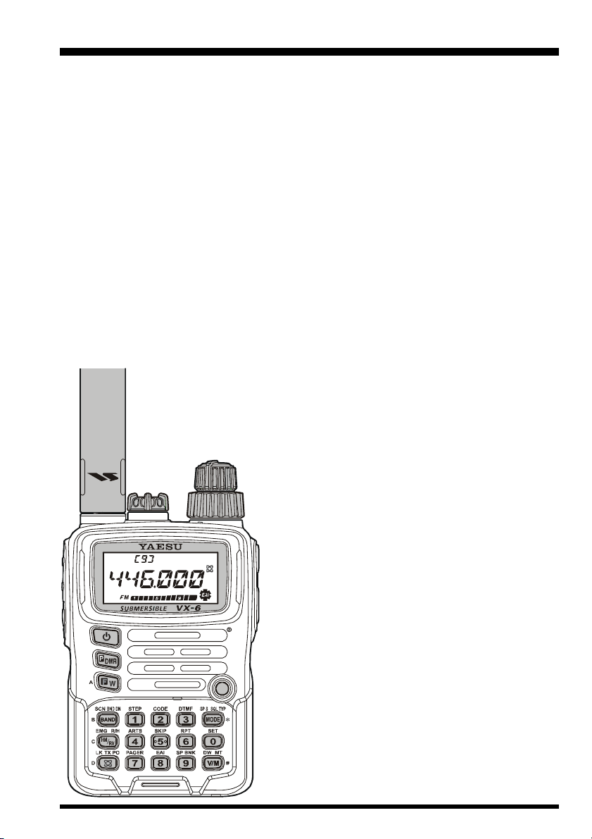
TOP & FRONT PANEL
)
POWER Switch
Press and hold in this switch for one second to
toggle the transceiver’s power on and off.
Keypad
These 18 keys select many of most important operating features on the VX-6R.
The functions of the keys are described
in detail on the pages to follow.
Microphone
The internal microphone is located here.
Speaker
The internal speaker is located here.
TX/BUSY Indicator Lamp
This indicator glows green when the squelch opens, and turns red during transmit.
During “Emergency Channel” operation (see page 62), this indicator will glow (or
flash) white. Also, this indicator can be useful as a flashlight in a dark environment via
Set Mode Item 34: LED LT; see page 96 for details.
VX-6R OPERATING MANUAL 3
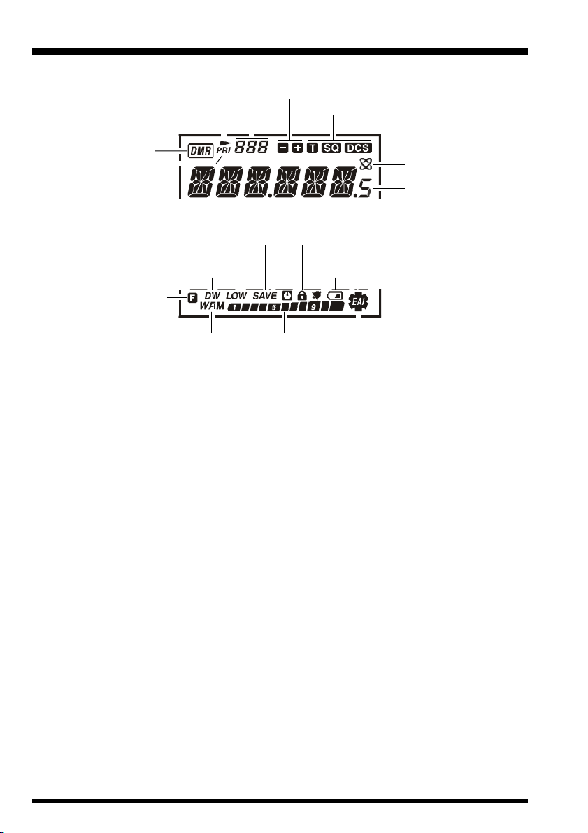
CONTROL & CONNECTIONS
Memory Channel Number
Skip Memory Channel or
Preferential Memory Channel
Repeater Shift Direction
(
)
LCD
CTCSS/DSC Operation
DMR Channel Recall
Priority Channel
Low TX Power Selected Bell Alarm Active
Dual Watch Active
Secondary Keypad Active
Battery Saver Active
Operating Mode
Internet Connection
Feature Active
Operating Frequency
Automatic Power-Off Active
Key Lock Active
Battery Indicator
S- & PO Meter
Emergency Automatic ID (EAI) Feature Active
VX-6R OPERATING MANUAL4
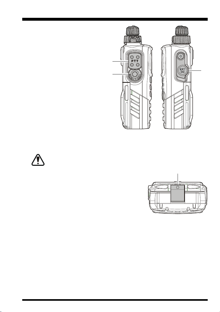
CONTROL & CONNECTIONS
PTT (Push To Talk) Switch
Press this switch to transmit, and release it (to receive) after your transmission is completed.
MONI Switch
Pressing this switch disables the
noise squelching action, allowing
you to hear very weak signals near
the background noise level temporarily.
Press the [F/W] key on the keypad
first, then press this switch to enable to adjustment of the squelch
threshold level.
EXT DC Jack
This coaxial DC jack allows connection to an external DC power source (6-16V DC).
The center pin of this jack is the Positive (+) connection.
Do not allow the VX-6R to become submerged in water while the rubber cap
over the EXT DC jack is removed.
(
SIDE & BOTTOM PANEL
)
Battery Pack Latch
Open this latch for battery removal.
VX-6R OPERATING MANUAL 5
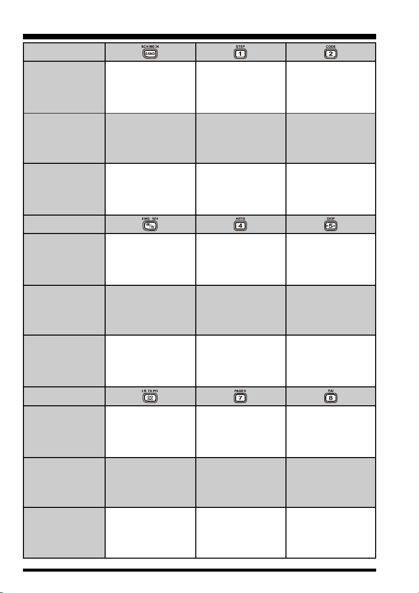
CONTROL & CONNECTIONS
(
KEYPAD
)
Primary Function
(
PRESS KEY
Secondary Function
(
PRESS [F/W] + KEY
Third Function
(
PRESS & HOLD KEY
Primary Function
(
PRESS KEY
Secondary Function
(
PRESS [F/W] + KEY
Third Function
(
PRESS & HOLD KEY
)
)
Moves operation to the
next-highest frequency
band
Moves operation to the
next-lowest frequency
)
)
a higher channel number)
Reverses the transmit
)
Switches to the “Home”
)
band
Starts the scanner
upward
(toward a higher
frequency or
and receive frequen-
cies while working
through a repeater
Activates the EMER-
GENCY function
(favorite frequency)
Channel
Frequency entry digit
“1”
Selects the synthesizer
steps to be used during
VFO operation.
Stores the current
setting into Direct
Memory Recall
Channel “1”
Frequency entry digit
Activates the ARTS
“4”
TM
feature
Stores the current
setting into Direct
Memory Recall
Channel “4”
Frequency entry digit
“2”
Selects the CTCSS
tone or DCS code
number
Stores the current
setting into Direct
Memory Recall
Channel “2”
Frequency entry digit
“5”
Selects the Memory
Scan “Skip” channel-
selection mode
Stores the current
setting into Direct
Memory Recall
Channel “5”
Primary Function
(
PRESS KEY
Secondary Function
(
PRESS [F/W] + KEY
Third Function
(
PRESS & HOLD KEY
)
Activates the Internet
Connection feature
Selects the desired
transmit power output
)
)
level
Activates the Key
Lockout feature
Frequency entry digit
“7”
Activates the EPCS
(Enhanced Paging &
Code Squelch) feature
Stores the current
setting into Direct
Memory Recall
Channel “7”
VX-6R OPERATING MANUAL6
Frequency entry digit
“8”
Activates the EAI
(Emergency Automatic
ID) feature
Stores the current
setting into Direct
Memory Recall
Channel “8”
TM
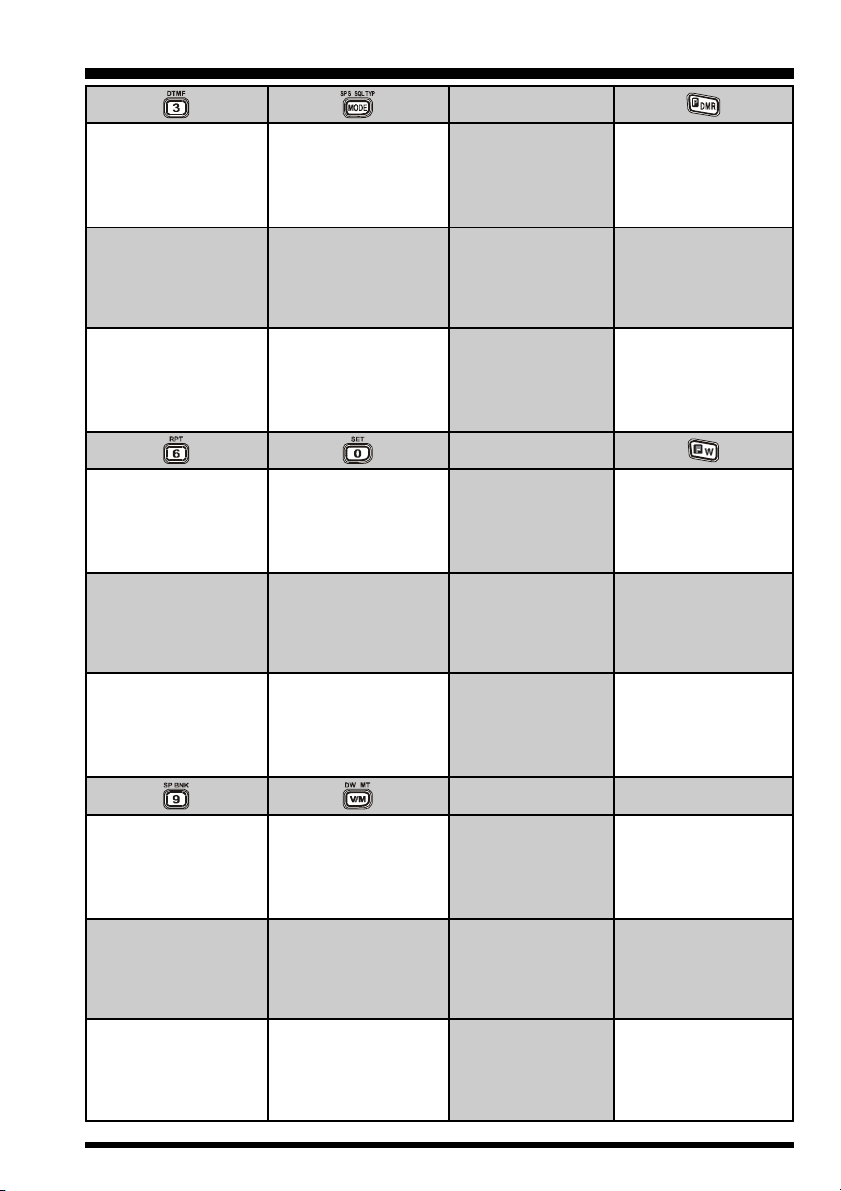
CONTROL & CONNECTIONS
(
KEYPAD
)
Frequency entry digit
“3”
Selects the DTMF
mode
Stores the current
setting into Direct
Memory Recall
Channel “3”
Frequency entry digit
“6”
Selects the direction of
the uplink frequency
shift (either “–,” “+,” or
“simplex”) during
repeater operation
Stores the current
setting into Direct
Memory Recall
Channel “6”
Selects the Receive
mode among AM, FM,
and Wide FM
Activates CTCSS or
DCS Operation
Engage the Special
Search mode
Frequency entry digit
“0”
Engages the Set
(Menu) Mode
Stores the current
setting into Direct
Memory Recall
Channel “0”
Primary Function
(
PRESS KEY
Secondary Function
(
PRESS [F/W] + KEY
Third Function
(
PRESS & HOLD KEY
Primary Function
(
PRESS KEY
Secondary Function
(
PRESS [F/W] + KEY
Third Function
(
PRESS & HOLD KEY
)
)
Activates the “User
Programmed” mode
)
)
)
)
No Action
Activates the Direct
Memory Recall
Channel function
Activates the “Second-
ary” key function
Disables the “Second-
ary” key function
Activates the “Memory
Write” mode (for
memory channel
storage)
Frequency entry digit
“9”
Enter the Special Bank
mode
Stores the current
setting into Direct
Memory Recall
Channel “9”
Switches frequency
control between the
VFO and Memory
Systems
Activates the “Memory
Tune” mode while in
the Memory Recall
mode
Activates the Priority
(Dual Watch) function
Primary Function
(
PRESS KEY
Secondary Function
(
PRESS [F/W] + KEY
Third Function
(
PRESS & HOLD KEY
)
)
)
VX-6R OPERATING MANUAL 7

INSTALLATION OF ACCESSORIES
ANTENNA INSTALLATION
The supplied antenna provides good results over the entire frequency range of the transceiver. However, for enhanced reception on certain non-Amateur frequencies, you may wish to connect an antenna designed specifically for that frequency range,
as the supplied antenna is necessarily a compromise outside the
Amateur bands, and cannot be expected to provide high performance at all frequencies.
To install the supplied antenna, hold the bottom end of the antenna, then screw it onto the mating connector on the transceiver
until it is snug. Do not over-tighten by use of extreme force.
Notes:
Never transmit without having an antenna connected.
When installing the supplied antenna, never hold the upper
part of the antenna while screwing it onto the mating connector on the transceiver.
If using an external antenna for transmission, ensure that the SWR presented to the
transceiver is 1.5:1 or lower, to avoid excessive feedline loss.
BELT CLIP & HAND STRAP INSTALLATION
VX-6R OPERATING MANUAL8
INSTALLATION OF ACCESSORIES
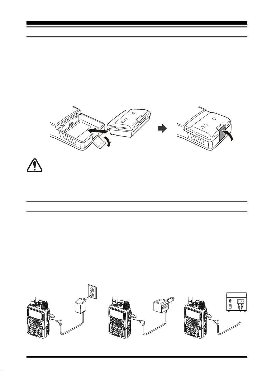
INSTALLATION OF FNB-80LI BATTERY PACK
The FNB-80LI is a high-performance Lithium-Ion battery providing high capacity in a
very compact package. Under normal use, the FNB-80LI may be used for approximately
300 charge cycles, after which operating time may be expected to decrease. If you have an
old battery pack which is displaying capacity which has become diminished, you should
replace the pack with a new one.
Install the FNB-80LI as shown in the illustration.
Close the Battery Pack Latch on the bottom of the radio.
1) Do not attempt to open any of the rechargeable Li-Ion packs, as personal
injury or damage to the Li-Ion pack could occur if a cell or cells become acci-
dentally short-circuited.
2) Danger of explosion if battery is incorrectly replaced. Replace only with the same or
equivalent type.
BATTERY CHARGING
If the battery has never been used, or its charge is depleted, it may be charged by connecting the NC-72B/C Battery Charger, as shown in the illustration, to the EXT DC jack. If
only 12 ~ 16 Volt DC power is available, the optional E-DC-5B or E-DC-6 DC Adapter
(with its cigarette lighter plug) may also be used for charging the battery.
The display will indicate “CHGING,” and the TX/BUSY indicator will glow red, while the
battery is being charged. When charging is finished, the display will change to indicate
“CHGFUL” and the TX/BUSY indicator will glow green.
AC line Outlet
NC-72
VX-6R OPERATING MANUAL 9
E-DC-5B E-DC-6
INSTALLATION OF ACCESSORIES
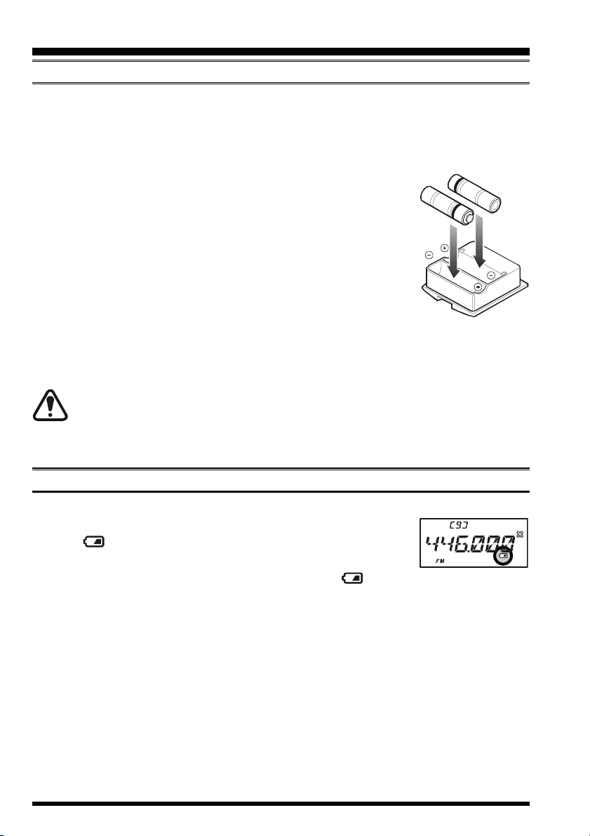
INSTALLATION OF FBA-23 ALKALINE BATTERY CASE (OPTION
The optional FBA-23 Battery Case allows receive monitoring using two “AA” size Alkaline batteries. Alkaline batteries can also be used for transmission in an emergency, but
power output will only be selectable 300 mW and 50 mW, and battery life will be shortened dramatically.
To Install Alkaline Batteries into the FBA-23
Slide the batteries into the FBA-23 as shown in the illustration,
with the Negative [–] side of the batteries touching the spring
connections inside the FBA-23.
Open the Battery Pack Latch on the bottom of the radio.
Install the FBA-23 as shown in the illustration, with the [+] side
facing the bottom of the transceiver.
Close the Battery Pack Latch on the bottom of the radio.
The FBA-23 does not provide connections for charging, since Alkaline cells cannot be recharged. Therefore, the NC-72B/C, E-DC-5B, or E-DC-6 may safely be connected to the
EXT DC jack when the FBA-23 is installed.
1) The FBA-23 is designed for use only with AA-type Alkaline cells.
2) If you do not use the VX-6R for a long time, remove the Alkaline batteries
from the FBA-23, as battery leakage could cause damage to the FBA-23 and/or the
transceiver.
)
LOW BATTERY INDICATION
As your battery discharges during use, the voltage will gradually become lower. When
the battery voltage is becoming too low for reliable operation,
the “ ” icon will blink on the LCD display, indicating that the
battery pack must be recharged before further use.
Avoid recharging Lithium-Ion batteries before the “ ” indicator is observed, as this
can degrade the charge capacity of your Lithium-Ion battery pack.
VX-6R OPERATING MANUAL10
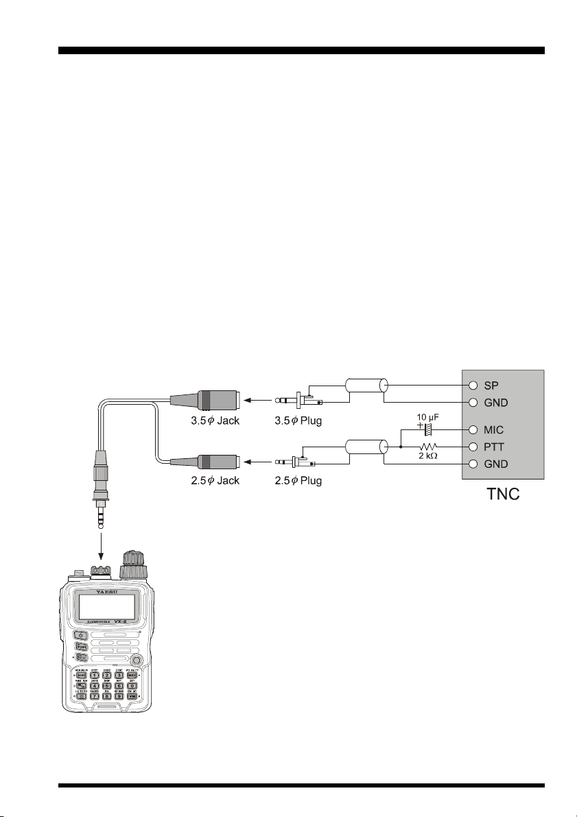
INTERFACE OF PACKET TNCS
The VX-6R may be used for Packet operation, using the optional CT-91 microphone adapter
(available from your Yaesu dealer) for easy interconnection to commonly-available connectors wired to your TNC. You may also build your own cable, using a four-conductor
miniature phone plug, per the diagram below.
The audio level from the receiver to the TNC may be adjusted by using the VOL knob, as
with voice operation. The input level to the VX-6R from the TNC may be adjusted via Set
Mode Item 37: MCGAIN; see page 18 for details.
Be sure to turn the transceiver and TNC off before connecting the cables, so as to prevent
voltage spikes from possibly damaging your transceiver.
When you are operating on Packet, switch the Receive Battery Saver OFF, as the “sleep”
cycle may “collide” with the beginning of an incoming Packet transmission, causing your
TNC not to receive the full data burst. See page 77 for details regarding Receive Battery
Saver setup. Remember to readjust the default microphone input level to “LVL 5” (Set
Mode Item 37: MCGAIN) when Packet operation is finished.
VX-6R OPERATING MANUAL 11
OPERATION
Hi! I’m R. F. Radio, and I’ll be helping you along as you learn the many
features of the VX-6R. I know you’re anxious to get on the air, but I encour-
age you to read the “Operation” section of this manual as thoroughly as
possible, so you’ll get the most out of this fantastic new transceiver. Now. . .let’s get
operating!
SWITCHING POWER ON AND OFF
1. Be sure the Battery Pack is installed, and that the bat-
tery is fully charged. Connect the antenna to the top
panel ANTENNA jack.
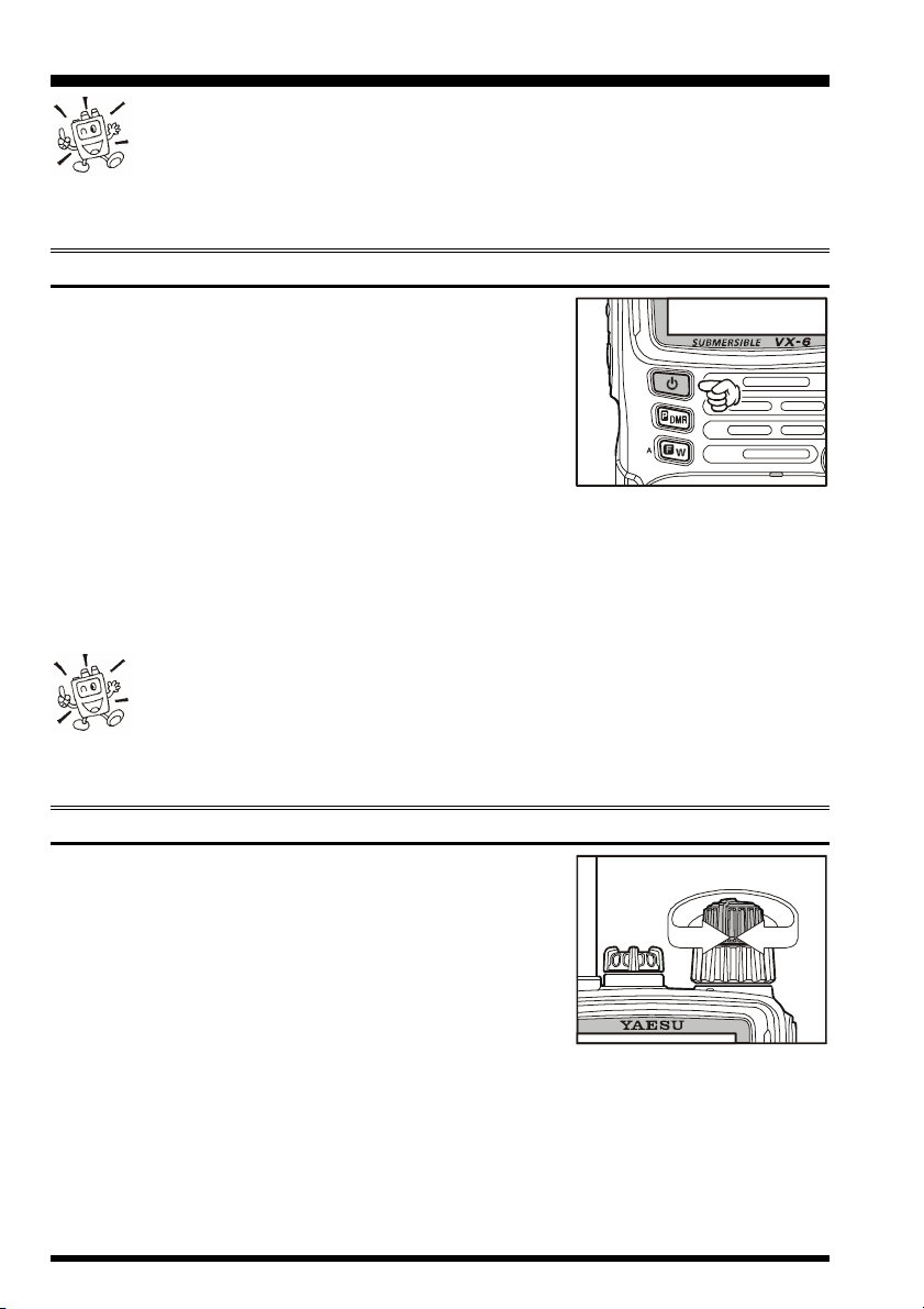
2. Press and hold in the orange POWER switch (on the
left side of the front panel) for one second. Two beeps
will be heard when the switch has been held long
enough, and the current DC supply voltage will indicated on the display for 2 seconds; if you are using the FNB-80LI Battery Pack, the
small “Lit” notation at the top of the display confirms that the Lithium-Ion Battery
Pack has been detected. After this 2-second interval, the display will resume its normal
indication of the operating frequency.
3. To turn the VX-6R off, press and hold in the POWER switch again for one second.
1) If you don’t hear the two “Beep” tones when the radio comes on, the Beeper
may have been disabled via the Menu system. See page 21, which tells you
how to reactivate the Beeper.
2) You can change the Opening Message (DC supply voltage indication) to any desired
message (up to 6 characters) via Set Mode Item 42: OPN.MSG; see page 48 for details.
ADJUSTING THE VOLUME LEVEL
Rotate the VOLUME control (inner knob) to set the desired audio level. Clockwise rotation increases the volume
level.
VX-6R OPERATING MANUAL12
OPERATION
SQUELCH ADJUSTMENT
The VX-6R’s Squelch system allows you to mute the background noise when no signal is
being received. Not only does the Squelch system make “standby” operation more pleasant, it also significantly reduces battery current consumption.
The Squelch system may be adjusted independently for the FM and Wide-FM (FM Broadcast) modes. AM utilizes the setting chosen for FM.
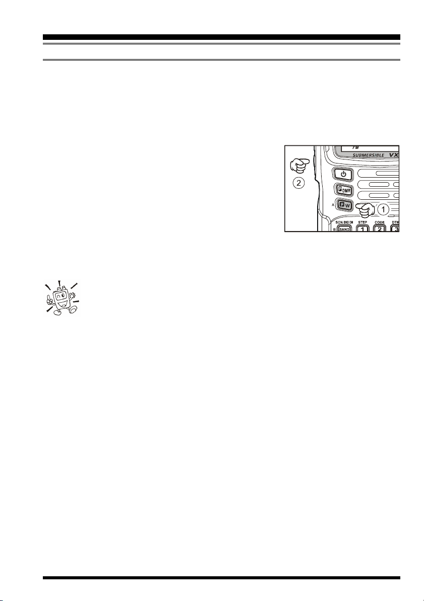
1. Press the [F/W] key, then press the MONI switch on
the left side of the radio. This provides a “Short-cut” to
Set Mode Item 58: SQL.
2. Now, rotate the DIAL knob to set the Squelch so that
the background noise is just silenced (typically at a setting of about “1” or “2” for FM and AM, and “2” or
“3” for Wide-FM); this is point of maximum sensitivity to weak signals.
3. When you are satisfied with the Squelch threshold setting, press the PTT key momentarily to save the new setting and exit to normal operation.
1) A special “RF Squelch” feature is provided on the VX-6R. This feature
allows you to set the squelch so that only signals exceeding a certain S-meter
level will open the squelch. See page 23 for details.
2) If you’re operating in an area of high RF pollution, you may need to consider “Tone
Squelch” operation using the built-in CTCSS Decoder. This feature will keep your radio quiet until a call is received from a station sending a carrier which contains a matching
(subaudible) CTCSS tone. Or, if your friends have radios equipped with DCS (Digital
Coded Squelch) like your VX-6R has, try using that mode for silent monitoring of busy
channels.
VX-6R OPERATING MANUAL 13
OPERATION
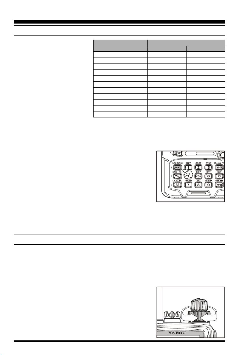
SELECTING THE OPERATING BAND
The VX-6R covers an incredibly
wide frequency range, over
which a number of different operating modes are used. Therefore, the VX-6R’s frequency coverage has been divided into different operating bands, each of
which has its own pre-set channel steps and operating modes.
You can change the channel steps
and operating modes later, if you
BC Band
SW Band
50 MHz Ham Band[3
FM BC Band
Air Band
144 MHz Ham Band[6]137 - 174 MHz 137 - 174 MHz
VHF-TV Band
222 MHz Ham Band[8]222 - 420 MHz 222 - 420 MHz
430 MHz Ham Band[9]420 - 470 MHz 420 - 470 MHz
UHF-TV Band
Action Band
BAND
[
BAND NUMBER
like (see page 22).
To Change Operating Bands:
1. Press the [BAND(SCN)BND DN] key repetitively. You will see the LCD indication
move toward a higher frequency band each time you
press the [BAND(SCN)BND DN] key.
2. If you wish to move the operating band selection downward (toward lower frequencies), press the [F/W] key
first, then press the [BAND(SCN)BND DN] key.
3. Once you have selected the desired band, you may initiate manual tuning (or scanning) per the discussion in
the next chapter.
FREQUENCY RANGE
]
USA VERSION EXP VERSION
[1]
0.5 - 1.8 MHz 0.504 - 1.8 MHz
[2]
1.8 - 30 MHz 1.8 - 30 MHz
]
30 - 59 MHz 30 - 88 MHz
[4]
59 - 108 MHz 88 - 108 MHz
[5]
108 - 137 MHz 108 - 137 MHz
[7]
174 - 222 MHz 174 - 222 MHz
[A]
470 - 800 MHz 470 - 800 MHz
[b]
803 - 999 MHz 800 - 999 MHz
When receiving in the AM Broadcast or Shortwave bands (0.5-30 MHz), we recommend
that you connect an external antenna, for improved reception.
FREQUENCY NAVIGATION
The VX-6R will initially be operating in the “VFO” mode, a channelized system which
allows free tuning throughout the currently-selected operating band.
Three basic frequency navigation methods are available on the VX-6R:
1) Tuning Dial
Rotation of the DIAL allows tuning in the pre-programmed
steps established for the current operating band. Clockwise
rotation of the DIAL causes the VX-6R to be tuned toward
a higher frequency, while counter-clockwise rotation will
lower the operating frequency.
If you press the [F/W] key momentarily, then rotate the
VX-6R OPERATING MANUAL14
OPERATION
FREQUENCY NAVIGATION
DIAL, frequency steps of 1 MHz will be selected. This feature is extremely useful for
making rapid frequency excursions over the wide tuning range of the VX-6R.
2) Direct Keypad Frequency Entry
The desired operating frequency may be entered directly from the keypad.
To enter a frequency from the keypad, just press the numbered digits on the keypad in the
proper sequence. There is no “Decimal point” key on the VX-6R, so if the frequency is
below 100 MHz (e.g. 15.150 MHz), any required leading zeroes must be entered. However, there is a short-cut for frequencies ending in zero - press the [V/M(DW)MT] key after
the last non-zero digit.
Examples: To enter 146.520 MHz, press [1] [4] [6] [5] [6] [0
To enter 15.255 MHz, press [0] [1] [5] [2] [5] [5
To enter 1.250 MHz (1250 kHz), press [0] [0] [1] [2] [5] [0
To enter 0.950 MHz (950 kHz), press [0] [0] [0] [9] [5] [0
To enter 430.000MHz, press [4] [3] [V/M(DW)MT
]
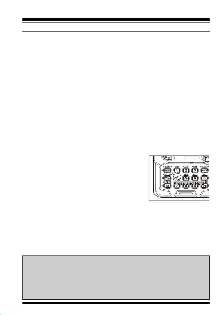
3) Scanning
From the VFO mode, press and hold in the [BAND(SCN)BND DN] key for one second,
and rotate the DIAL knob while holding in the
[
BAND(SCN)BND DN] key, to select the bandwidth for
the VFO scanner, then release the [BAND(SCN)BND DN
key to begin scanning toward a higher frequency. The scanner will stop when it receives a signal strong enough to break
through the Squelch threshold. The VX-6R will then hold
on that frequency according to the setting of the “RESUME”
mode (Set Mode Item 48: RESUME). See page 46 for details regarding Scan Operation.
]
]
]
]
]
If you wish to reverse the direction of the scan (i.e. toward a lower frequency, instead of a
higher frequency), just rotate the DIAL one click in the counter-clockwise direction while
the VX-6R is scanning. The scanning direction will be reversed. To revert to scanning
toward a higher frequency once more, rotate the DIAL one click clockwise.
Press the PTT switch momentarily to cancel the scanning. This only stops the scan; it does
not cause transmission to occur.
Notice
The VX-6R may receive very strong signals on the Image frequency. If you experience interference that you suspect may be coming in via an “Image” path, you may
calculate the possible frequencies using the formulas below. This information may be
used in the design of effective countermeasures such as traps, etc.
3.579545 MHz x n 11.7 MHz x n (n is an integer: 1, 2, 3, …)
VX-6R OPERATING MANUAL 15
OPERATION
TRANSMISSION
Once you have set up an appropriate frequency inside one of the 144 MHz, 222 MHz, or
430 MHz Amateur bands on which the VX-6R can transmit, you’re ready to go on the air!
These are the most basic steps; more advanced aspects of transmitter operation will be discussed later (222 MHz: USA version only).
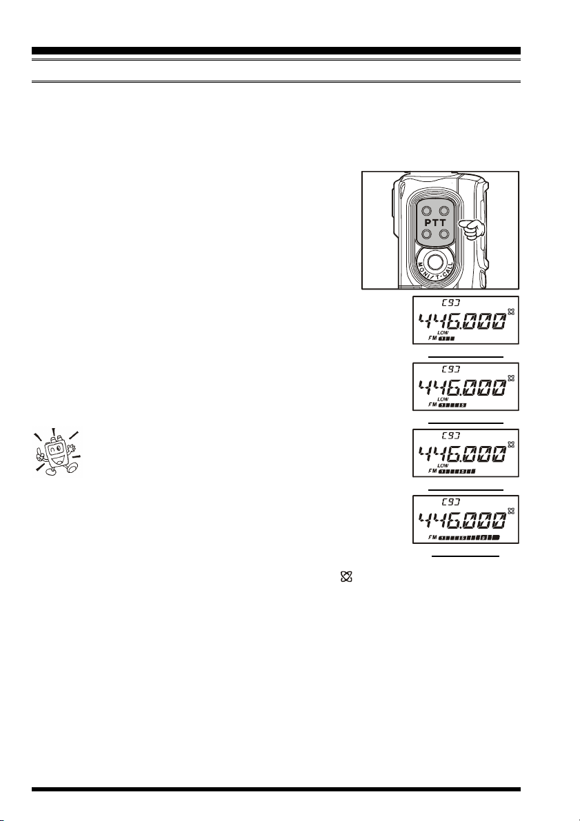
1. To transmit, press the PTT switch, and speak into the
front panel microphone (located in the upper right-hand
corner of the speaker grille) in a normal voice level.
The TX/BUSY indicator will glow red during transmission.
2. To return to the receive mode, release the PTT switch.
3. During transmission, the relative power level will be
indicated on the bar graph at the bottom of the LCD; full scale
deflection confirms “High Power” operation, while deflection
of three bars indicates “Low 1 Power” operation. Five bars indicates “Low 2 Power” operation and seven bars indicates “Low 3
Power” operation. Additionally, the “LOW” icon will appear at
the bottom of the display while operating on the “Low Power”
settings.
1) If you’re just talking to friends in the immediate area,
you’ll get much longer battery life by switching to Low
Power operation, described in the next chapter. And don’t
forget: always have an antenna connected when you transmit.
2) Transmission is possible only on the 144 MHz, 222 MHz (U.S.A.
version only), and 430 MHz bands.
3) If other users report that you always have a DTMF “beep” at the
beginning of each transmission, you may have accidentally switched
on the “Internet Connection” feature. Just press the [ (LK)TXPO] key momentarily
to disable this feature, which is described in detail on page 70.
4) When the power supply voltage is 14-volt or above, reduce the transmit power to
“Low 3” level automatically.
“LOW 1” POWER
“LOW 2” POWER
“LOW 3” POWER
“HIGH” POWER
VX-6R OPERATING MANUAL16

OPERATION
TRANSMISSION
Changing the Transmitter Power Level
You can select between a total of four transmitter power levels on your VX-6R. The exact
power output will vary somewhat, depending on the voltage supplied to the transceiver. With the standard FNB-
80LI Battery Pack and external DC source, the power output levels available are:
To change the power level:
1. The default setting for the power output is “High;” in
this configuration, the LCD shows
no indication of the power output
level. Pressing the [F/W] key, followed by the
[ (LK)
TXPO] key,
will display the current power output level.
2. Within one second of releasing the
[ (LK)
TXPO] key, press the
key repetitively; this will cause the power level “LOW1,” “LOW2,” or “LOW3” to
appear.
3. Press the [F/W] key, followed by the
[ (LK)
TXPO] key (repeatedly, if necessary) to
make the “HIGH” notation appear and restore High Power operation.
HIGH
LOW 3
LOW 2
LOW 1
144/430 MHz
5.0 W
2.5 W
1.0 W
0.3 W
[ (LK)
220 MHz
1.5 W
1.0 W
0.5 W
0.2 W
TXPO
]
1) The VX-6R is smart! You can set up Low power on the 144 MHz band,
while leaving 430 MHz on High power, and the radio will remember the
different settings on both bands. And when you store memories, you can store
the power output settings separately in each memory, so you don’t waste battery power
when using very close-in repeaters!
2) When you are operating on the “Low” power settings, you can press the [F/W] key,
then press the PTT switch, to cause the VX-6R to transmit (temporarily) on High power.
After one transmission, the power level will revert to the previously-selected setting.
VX-6R OPERATING MANUAL 17
OPERATION
TRANSMISSION
Changing the Microphone Gain Level
Different operators speak at different voice levels, and speak at varying distances from the
radio’s microphone. So as to compensate for these differences, the VX-6R includes a Microphone Gain control, that allows you to set the Microphone Gain to the best level according to your operating preferences. Here’s how to set the level:
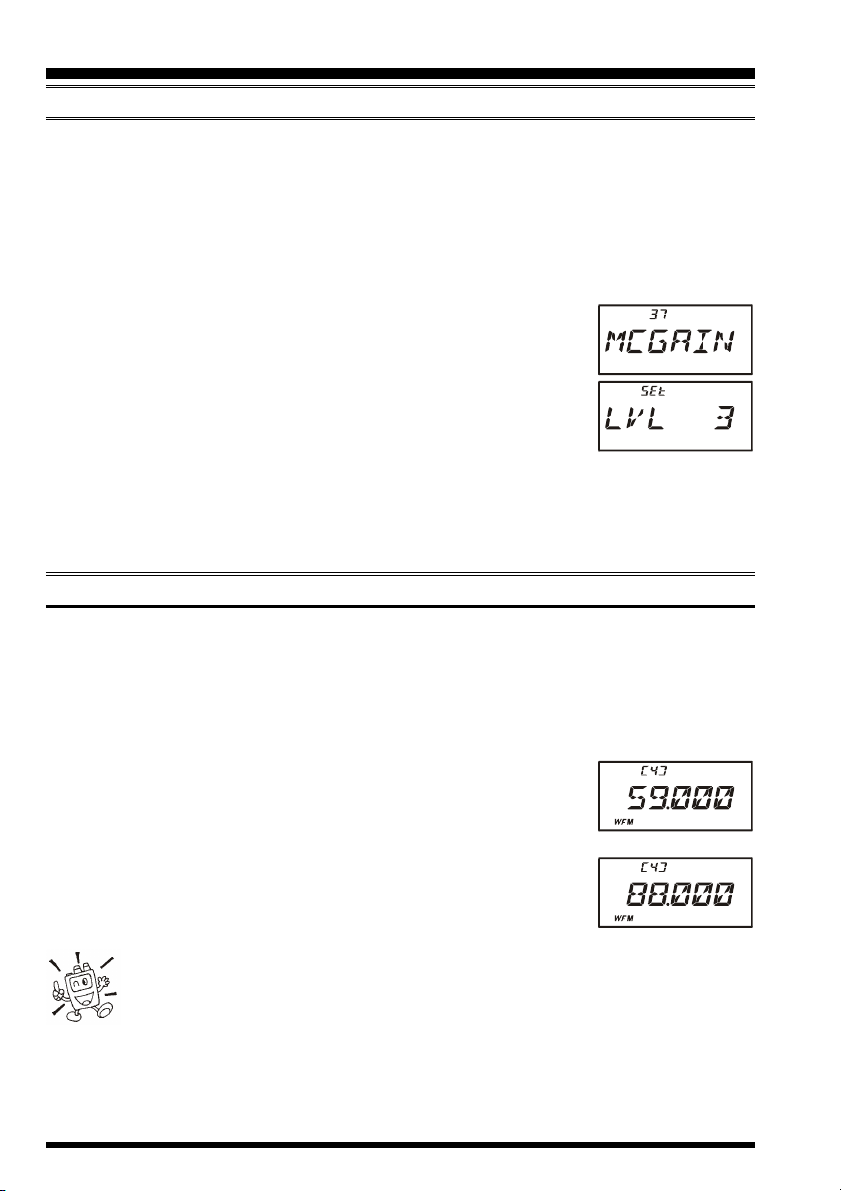
1. Press the [F/W] key, then press the [0(SET)] key to enter the Set mode.
2. Rotate the DIAL knob to select Set Mode Item 37: MCGAIN.
3. Press the [0(SET)] key momentarily to enable adjustment of this
Set Mode Item.
4. Rotate the DIAL knob to set the gain to a different level. The
default setting is “LVL 5;” if you wish to reduce the level, try a
setting or “LVL 3” or “LVL 4” while transmitting and speaking
into the microphone; you can hear the effects by monitoring on another radio tuned to
your operating frequency.
5. When you have made your selection, press and hold in the [0(SET)] key for 2 seconds
to save the new setting and exit to normal operation
AM BROADCAST RECEPTION
The VX-6R includes provision for reception of AM broadcasts, either on the standard
medium-wave (MW) broadcast band, or on the shortwave bands up to 30 MHz.
1. Press the [BAND(SCN)BND DN] key (or press the [F/W] key, followed by the
[
BAND(SCN)BND DN] key) repetitively until you see a frequency in the frequency
range desired. The MW coverage is 0.5 MHz to 1.8 MHz, while the shortwave broadcast coverage is 1.8 MHz to 30 MHz. In either case, the operating mode (displayed on the bottom left of the LCD) should be
shown as being “AM.”
2. Rotate the DIAL to tune across the broadcast band.
3. You may also use the keypad to enter frequencies directly. This
method will be quicker for changing from the 49-meter broadcast band to the 31-meter band, for example.
1) If the operating mode is not correct, you may change the operating mode
by pressing the [MODE(SP S)SQ TYP] key.
2) The VX-6R includes a special memory bank into which the factory has
stored 89 frequencies representing popular Short-wave Broadcast stations. See page 43
for details.
USA Version
EXP Version
VX-6R OPERATING MANUAL18
OPERATION
AM AIRCRAFT RECEPTION
Reception of AM signals in the aeronautical band (108-137 MHz) is similar to that described in the previous section.
1. Press the [BAND(SCN)BND DN] key (or press the [F/W] key, followed by the
[
BAND(SCN)BND DN] key) (repetitively, if necessary), until
you see a frequency in the aeronautical band.
2. Rotate the DIAL to tune across the aeronautical band.
3. You may also use the keypad to enter frequencies directly. Remember that frequencies
quoted by aircraft operators may be abbreviated, and that the “5” at the end of a frequency may be dropped. Since aeronautical channels are assigned in 25-kHz steps,
therefore, a frequency announced as “thirty-two, forty-two” corresponds to an operating frequency of 132.425 MHz.
FM BROADCAST/TV AUDIO RECEPTION
The VX-6R also includes provision for reception in the FM broadcast band, utilizing a
wide-bandwidth filter which provides excellent fidelity.
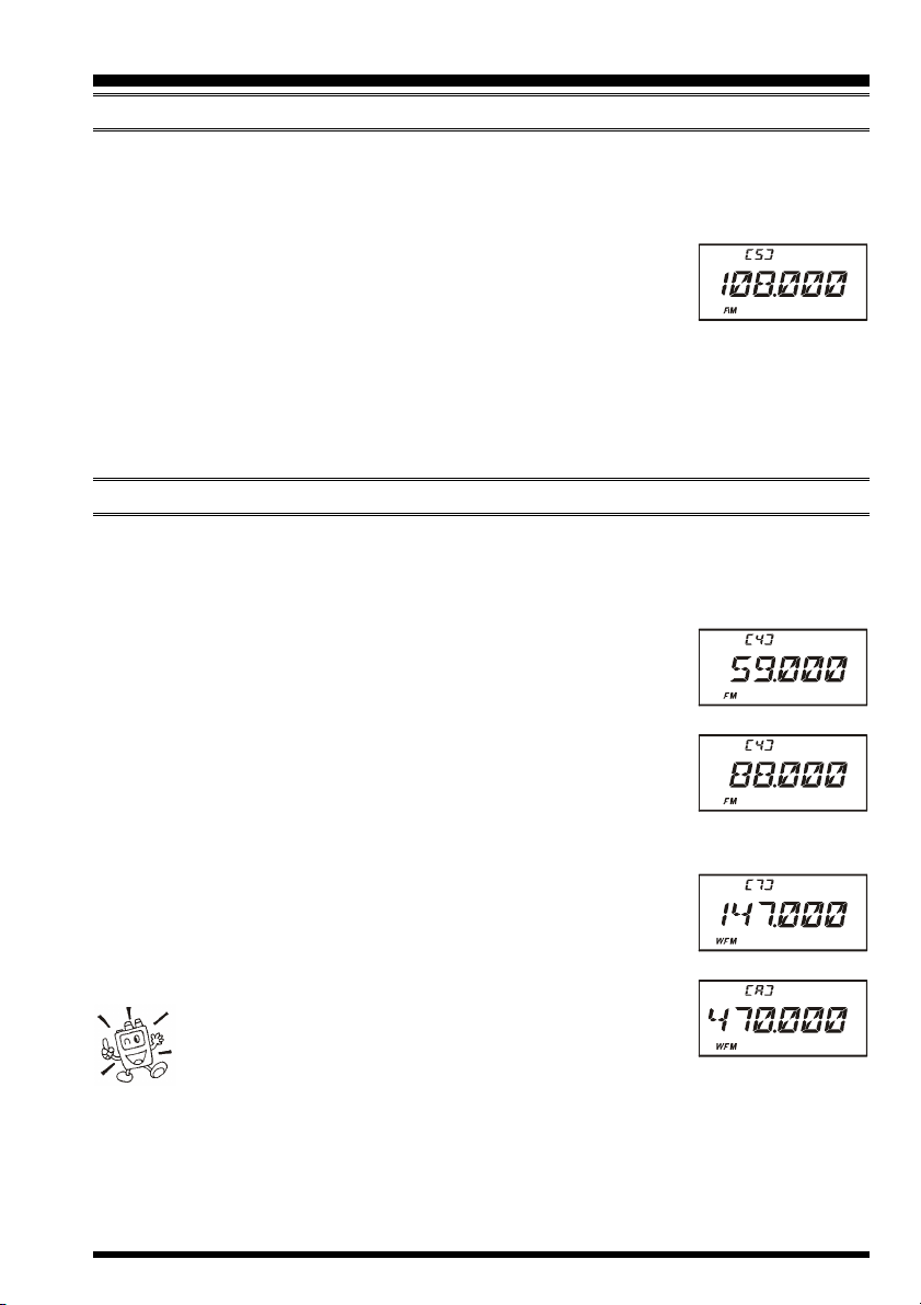
To Activate FM Broadcast Reception
1. Press the [BAND(SCN)BND DN] key (or press the [F/W] key,
followed by the [BAND(SCN)BND DN] key) repetitively until
a frequency in the FM broadcast band appears on the display.
The total frequency range included in the “FM” band is 59-108
MHz.
2. Rotate the DIAL to select the desired station. The default synthesizer steps for the W-FM mode are 100 kHz/step.
To Activate VHF or UHF TV Audio Reception
1. Press the [BAND(SCN)BND DN] key (or press the [F/W] key,
followed by the [BAND(SCN)BND DN] key) repetitively until
a frequency in the VHF or UHF TV bands appears on the LCD.
2. Rotate the DIAL to select the desired station.
USA Version
EXP Version
VHF TV Band
Remember that the Wide-FM Squelch setting may be
made independently from the Narrow-FM setting, adjust the Wide-FM Squelch setting by pressing the [F/W]
key, followed by the MONI switch while in the Wide-FM mode. See page 13 for details.
UHF TV Band
VX-6R OPERATING MANUAL 19

ADVANCED OPERATION
Now that you’re mastered the basics of VX-6R operation, let’s learn more about some of
the really neat features.
KEYBOARD LOCKING
In order to prevent accidental frequency change or inadvertent transmission, various aspects of the VX-6R’s DIAL and keypad may be locked out. The possible lockout combinations are:
KEY: Just the front panel keypad is locked out
DIAL: Just the top panel DIAL is locked out
K+D: Both the keypad and DIAL are locked out (factory default)
PTT: The PTT switch is locked out (TX not possible)
K+P: Both the keypad and PTT switch are locked out
D+P: Both the DIAL and PTT switch are locked out
ALL: All of the above are locked out
To lock out some or all of the keys:
1. Press the [F/W] key, then press the [0(SET)] key to enter the Set mode.
2. Rotate the DIAL knob to select Set Mode Item 35: LOCK.
3. Press the [0(SET)] key momentarily to enable adjustment of this
Item.
4. Rotate the DIAL knob to choose between one of the locking
schemes as outlined above.
5. When you have made your selection, press the PTT switch to
save the new setting and return to normal operation.
To activate the locking feature, press and hold in the
[ (LK)
pear on the LCD. To cancel locking, repeat this process.
TXPO] key for 2 seconds. The “ ” icon will ap-
VX-6R OPERATING MANUAL20
ADVANCED OPERATION
ADJUSTING THE KEYPAD BEEPER VOLUME LEVEL
A keypad beeper provides useful audible feed back whenever a keypad is pressed. The
keypad beeper level changes according to the VOL konb setting. However, you may adjust
the volume balance between the receiving audio and keypad beeper via the Set mode.
1. Press the [F/W] key, then press the [0(SET)] key to enter the Set mode.
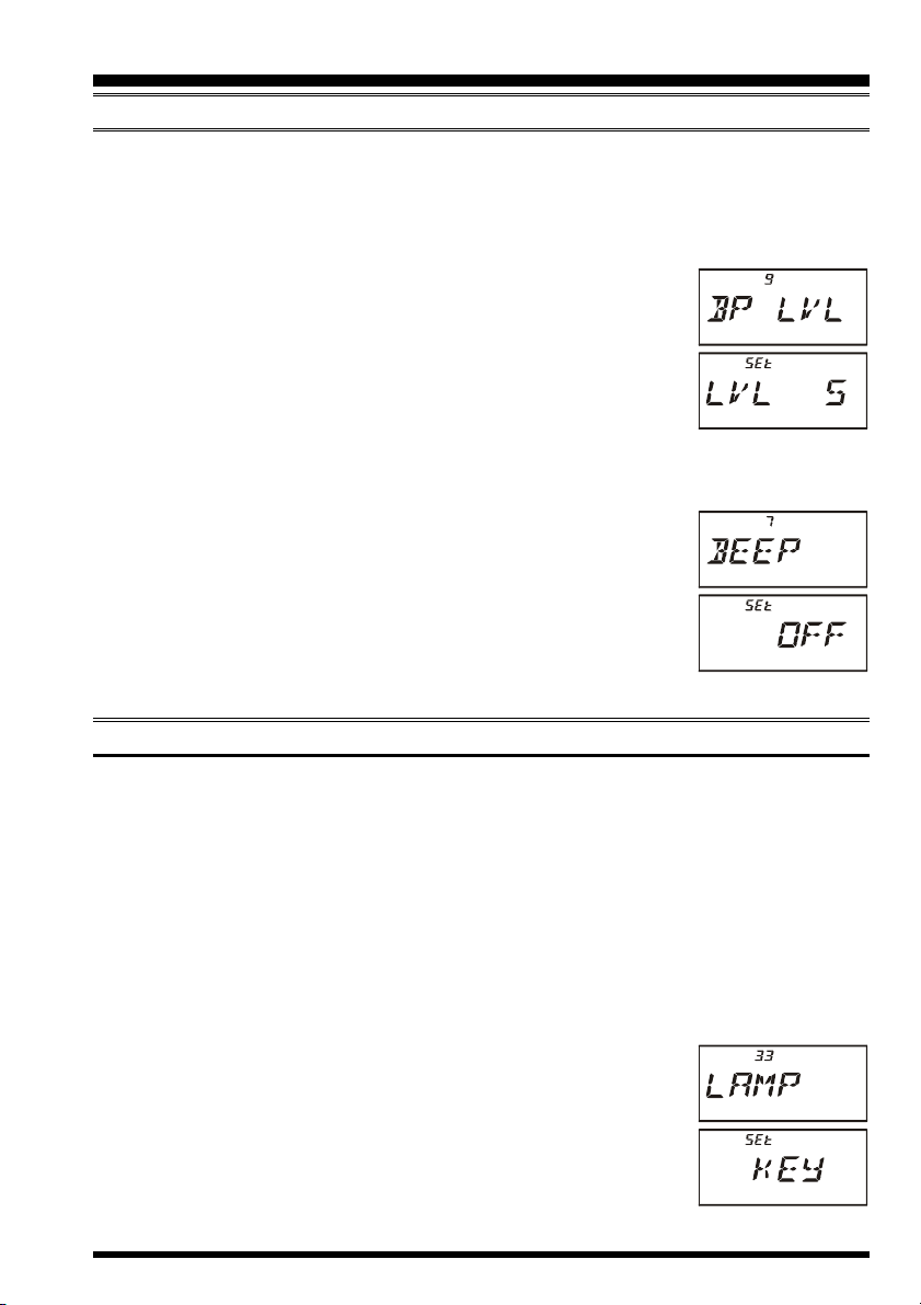
2. Rotate the DIAL knob to select Set Mode Item 9: BP LVL.
3. Press the [0(SET)] key momentarily to enable adjustment of this
Item.
4. Rotate the DIAL knob to select the desired level.
5. Press the PTT switch to save the new setting and return to normal operation.
Additionally, if you want to turn the beep off:
1. Press the [F/W] key, then press the [0(SET)] key to enter the Set mode.
2. Rotate the DIAL knob to select Set Mode Item 7: BEEP.
3. Press the [0(SET)] key momentarily to enable adjustment of this
Item.
4. Rotate the DIAL knob to change the setting to “OFF.”
5. Press the PTT switch to save the new setting and return to normal operation.
6. To turn the beep back on again, select “ON” in step 4 above.
KEYPAD/LCD ILLUMINATION
Your VX-6R includes a reddish illumination lamp which aids in nighttime operation. The
reddish illumination yields clear viewing of the display in a dark environment, with minimal degradation of your night vision.
Three options for activating the lamp are provided:
KEY Mode: Illuminates the Keypad/LCD for 5 seconds when any key pressed.
CONT Mode: Illuminates the Keypad/LCD continuously.
OFF Mode: Disables the Keypad/LCD lamp.
Here is the procedure for setting up the Lamp operating mode:
1. Press the [F/W] key, then press the [0(SET)] key to enter the Set mode.
2. Rotate the DIAL knob to select Set Mode Item 33: LAMP.
3. Press the [0(SET)] key momentarily to enable adjustment of this
Item.
4. Rotate the DIAL knob to select one of the three modes described
above.
5. When you have made your choice, press the PTT switch to save
the new setting and return to normal operation.
VX-6R OPERATING MANUAL 21
ADVANCED OPERATION
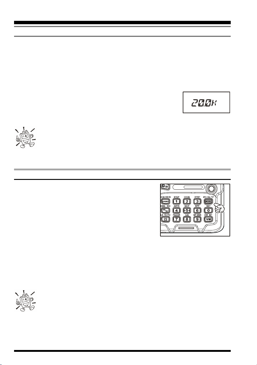
CHANGING THE CHANNEL STEPS
The VX-6R’s synthesizer provides the option of utilizing channel steps of 5/10/12.5/15/
20/25/50/100 kHz per step, as well as an automatic step selection based on the current
operating frequency (“AUTO”), any number of which may be important to your operating
requirements. The VX-6R is set up at the factory in the “AUTO” configuration, which
probably is satisfactory for most operation. However, if you need to change the channel
step increments, the procedure to do so is very easy.
1. Press the [F/W] key, then press the [1(STEP)] key. This pro-
vides a “Short-cut” to Set Mode Item 61: STEP.
2. Rotate the DIAL to select the new channel step size.
3. Press the PTT key to save the new setting and exit to normal operation.
1) 9 kHz steps are available only when receiving on the BC band.
2) While operating on the BC band, you may only select channel steps of 9
kHz or 10 kHz; the other step selections are disabled.
3) 5 kHz and 15 kHz steps are not available for use on 250 - 300 MHz, nor above 580
MHz.
CHANGING THE RECEIVING MODE
The VX-6R provides for automatic receiving mode changing when the radio is tuned to different operating frequencies. However, should an unusual receiving situation arise
in which you need to change other receiving mode, just press
the [MODE(SP S)SQ TYP] key. The receiving modes
available are:
AUTO: Automatic mode setting per default values for
the selected frequency range.
FM: Frequency Modulation for receiving an Amateur Radio Station and most VHF/
UHF Communication.
WFM: Frequency Modulation for receiving an FM Broadcast Station.
AM: Amplitude Modulation for receiving a Short-wave Broadcast Station and Air
Band Communication.
Unless you have a compelling reason to do so, leave the Automatic Mode
Selection feature on so as to save time and trouble when changing bands. If
you make a mode change for a particular channel or station, you can always
store that one channel into memory, as the mode setting will be memorized along with
the frequency information.
VX-6R OPERATING MANUAL22
ADVANCED OPERATION
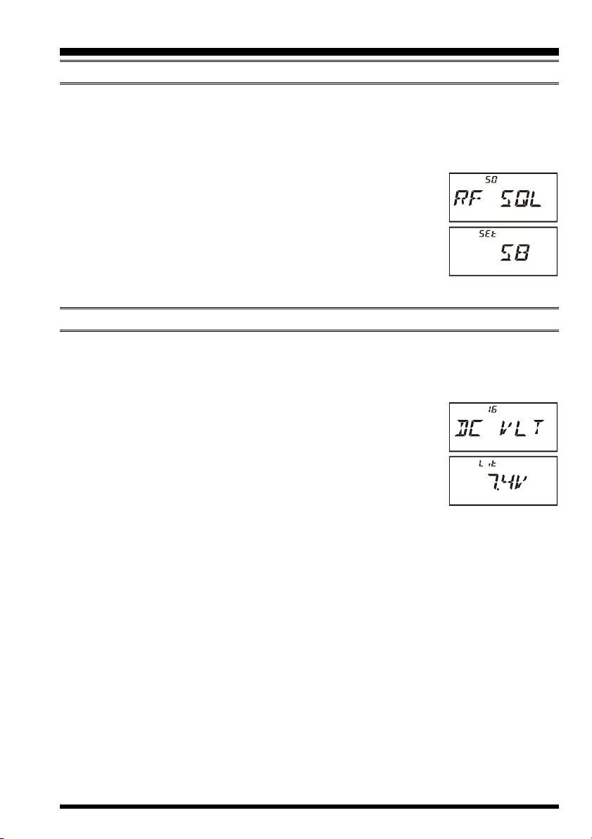
RF SQUELCH
A special RF Squelch feature is provided on this radio. This feature allows you to set the
squelch so that only signals exceeding a certain S-meter level will open the squelch.
To set up the RF squelch circuit for operation, use the following procedure:
1. Press the [F/W] key, then press the [0(SET)] key to enter the Set mode.
2. Rotate the DIAL knob to select Set Mode Item 50: RF SQL.
3. Press the [0(SET)] key momentarily to enable adjustment of this
Item.
4. Rotate the DIAL knob to select the desired signal strength level
for the squelch threshold (S1, S2, S3, S4, S5, S6, S7, S8, S9,
S9+, or OFF).
5. Press the PTT switch to save the new setting and return to normal operation.
CHECKING THE BATTERY VOLTAGE
The VX-6R’s microprocessor includes programming which will measure the current battery voltage.
1. Press the [F/W] key, then press the [0(SET)] key to enter the Set mode.
2. Rotate the DIAL knob to select Set Mode Item 16: DC VLT.
3. Press the [0(SET)] key momentarily to display the current DC
voltage being supplied.
Lit: FNB-80LI is in use.
Edc: An external DC source is in use.
4. Press and hold in the [0(SET)] key for 2 seconds to return to
normal operation.
VX-6R OPERATING MANUAL 23
REPEATER OPERATION
Repeater stations, usually located on mountaintops or other high locations, provide a dramatic extension of the communication range for low-powered hand-held or mobile transceivers. The VX-6R includes a number of features which make repeater operation simple
and enjoyable.
REPEATER SHIFTS
Your VX-6R has been configured, at the factory, for the repeater shifts customary in your
country. For the 144 MHz band shift will be 600 kHz and 222 MHz band (USA version
only) shift will be 1.6 MHz; on the 430 MHz band, the shift may be 1.6 MHz, 7.6 MHz, or
5 MHz (USA version).
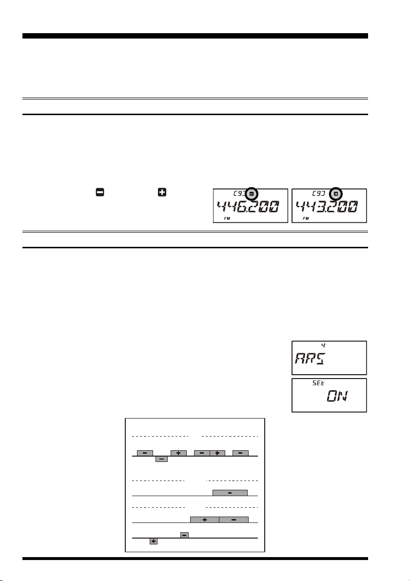
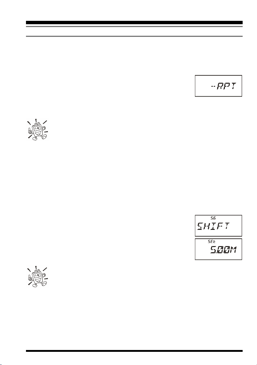
Depending on the part of the band in which you are operating, the repeater shift may be
either downward
( )
or upward
of these icons will appear at the top of the LCD
when repeater shifts have been enabled.
( )
, and one
AUTOMATIC REPEATER SHIFT (ARS
)
The VX-6R provides a convenient Automatic Repeater Shift feature, which causes the
appropriate repeater shift to be applied automatically whenever you tune into the designated repeater sub-bands in your country. These sub-bands are shown below.
If the ARS feature does not appear to be working, you may have accidentally disabled it.
To re-enable ARS:
1. Press the [F/W] key, then press the [0(SET)] key to enter the Set mode.
2. Rotate the DIAL knob to select Set Mode Item 4: ARS.
3. Press the [0(SET)] key momentarily to enable adjustment of this
Item.
4. Rotate the DIAL knob to select “ON.”
5. When you have made your selection, press the PTT switch to
save the new setting and return to normal operation.
ARS-Repeater Subbands
145.1 145.5
145.6 145.8
US A Ver sio n
US A Ver sio n
433.00 433.40
2-m
USA Version
146.0 146 .4 147.0 147 .6 148.0
146.6 147.4
EXP Version
1.25 m-
70-cm
440.0
439.45438.20
EXP Versio n 2
223.92
EXP Version 1
224.98
445.0 450.0
VX-6R OPERATING MANUAL24
REPEATER OPERATION
MANUAL REPEATER SHIFT ACTIVATION
If the ARS feature has been disabled, or if you need to set a repeater shift direction other
than that established by the ARS, you may set the direction of the repeater shift manually.
To do this:
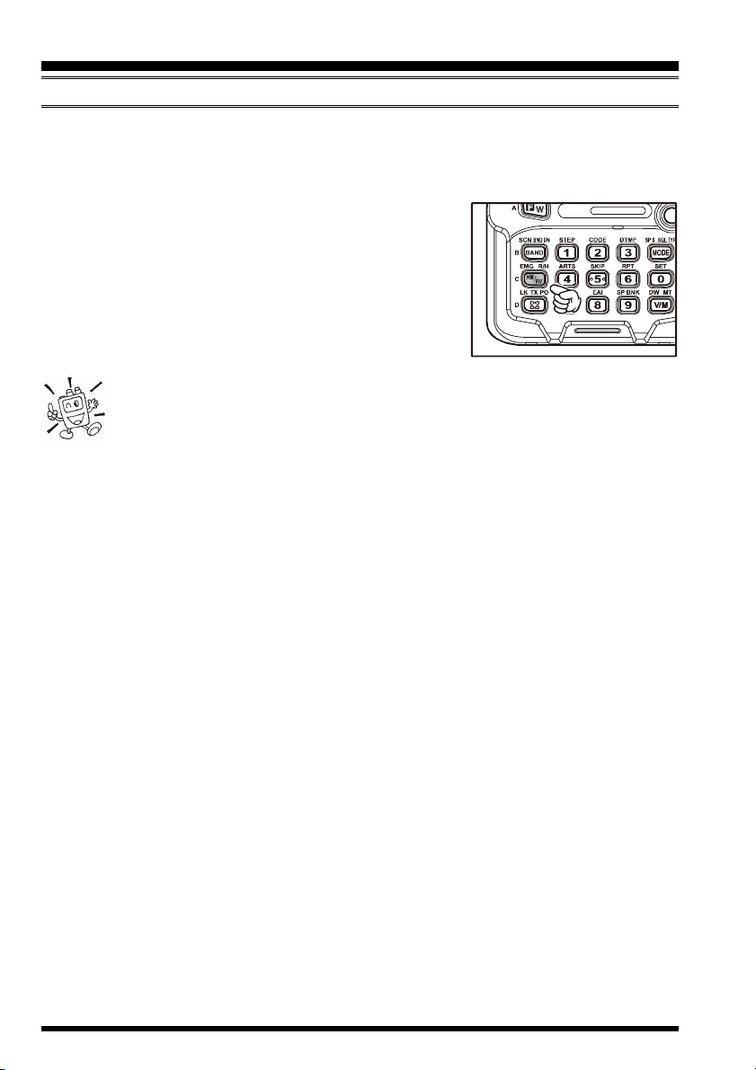
1. Press the [F/W] key, then press the [6(RPT)] key. This provides a “Short-cut” to Set
Mode Item 51: RPT.
2. Rotate the DIAL knob to select the desired shift among “–RPT,”
“+RPT,” and “SIMP.”
3. When you have made your selection, press the PTT switch to save the new setting and
return to normal operation.
If you make a change in the shift direction, but still have Automatic Repeater
Shift still engaged (see previous section), when you change frequency (by
rotating the DIAL knob, for example) the ARS will over-ride your manual
setting of the shift direction. Turn ARS off if you do not wish this to happen.
Changing the Default Repeater Shifts
If you travel to a different region, you may need to change the default repeater shift so as to
ensure compatibility with local operating requirements.
To do this, follow the procedure below:
1. Set the VX-6R’s frequency to the band on which you wish to change the default re-
peater shift (144 MHz or 430 MHz Amateur Band).
2. Press the [F/W] key, then press the [0(SET)] key to enter the Set mode.
3. Rotate the DIAL knob to select Set Mode Item 56: SHIFT.
4. Press the [0(SET)] key momentarily to enable adjustment of this
Item.
5. Rotate the DIAL knob to select the new repeater shift magnitude.
6. When you have made your selection, press the PTT switch to
save the new setting and return to normal operation.
If you just have one “odd” split that you need to program, don’t change the
“default” repeater shifts using this Set Mode Item. Enter the transmit and
receive frequencies separately, as shown on page 34.
VX-6R OPERATING MANUAL 25
REPEATER OPERATION
MANUAL REPEATER SHIFT ACTIVATION
Checking the Repeater Uplink (Input) Frequency
It often is helpful to be able to check the uplink (input) frequency of a repeater, to see if the
calling station is within direct (“Simplex”) range.
To do this, just press the [HM/RV(EMG)R/H] key. You’ll
notice that the display has shifted to the repeater uplink frequency. Press the [HM/RV(EMG)R/H] key again to cause
operation to revert to normal monitoring of the repeater
downlink (output) frequency. While you are listening on the
input frequency to the repeater using the [HM/RV(EMG
R/H] key, the repeater offset icon will blink.
The configuration of this key may be set either to “RV” (for checking the
input frequency of a repeater), or “HM” (for instant switching to the “Home”
channel for the band you are operating on). To change the configuration of
this key, use Set Mode Item 28: HM/RV. See page 45.
)
VX-6R OPERATING MANUAL26
CTCSS/DCS OPERATION
CTCSS OPERATION
Many repeater systems require that a very-low-frequency audio tone be superimposed on
your FM carrier in order to activate the repeater. This helps prevent false activation of the
repeater by radar or spurious signals from other transmitters. This tone system, called
“CTCSS” (Continuous Tone Coded Squelch System), is included in your VX-6R, and is
very easy to activate.
CTCSS setup involves two actions: setting the Tone Mode and then setting of
the Tone Frequency. These actions are set up by using the [MODE(SP S)
SQ TYP] key and [2(CODE)] key.
1. Press the [F/W] key, then press the [MODE(SP S)SQ TYP] key to enable selection
of the CTCSS/DCS mode.
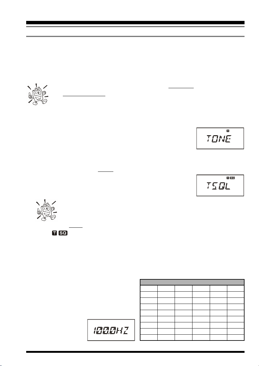
2. Rotate the DIAL knob so that the “TONE” indication appears on
the display; this activates the CTCSS Encoder, for access to repeaters requiring a CTCSS tone.
3. Rotation of the DIAL knob one more “click” in step “2” above will cause the “T SQL”
notation to appear. When “T SQL” is displayed, this means that the Tone SQueLch
system is active, which mutes your VX-6R’s receiver until it receives a call from
another radio sending out a matching CTCSS tone. This can help
keep your radio quiet until a specific call is received, which may
be helpful while operating in congested areas of the band.
1) You may notice a “RV TN” indication on the display while you rotate
the DIAL knob in this step; this means that the Reverse Tone Squelch
system is active, which mutes your VX-6R’s receiver (instead of opening
the squelch) when it receives a call from the radio sending a matched CTCSS tone.
The “ ” icon will blink on the display when the Reverse Tone Squelch system
is activated.
2) You may notice a “DCS” indication on the display while you rotate the DIAL
knob still more. We’ll discuss the Digital Code Squelch system shortly.
4. When you have made your selection of the CTCSS tone mode, press the PTT switch
to save the new setting.
5. Press the [F/W] key, then press the
[2(
CODE)] key to enable adjustment of
the CTCSS frequency.
6. Rotate the DIAL knob until the display
indicates the Tone Frequency you need to
be using (ask the repeater owner/operator if you don’t
know the tone frequency).
CTCSS TONE FREQUENCY (Hz
67.0 69.3 71.9 74.4 77.0 79.7
82.5 85.4 88.5 91.5 94.8 97.4
100.0 103.5 107.2 110.9 114.8 118.8
123.0 127.3 131.8 136.5 141.3 146.2
151.4 156.7 159.8 162.2 165.5 167.9
171.3 173.8 177.3 179.9 183.5 186.2
189.9 192.8 196.6 199.5 203.5 206.5
210.7 218.1 225.7 229.1 233.6 241.8
250.3 254.1 – – – –
)
VX-6R OPERATING MANUAL 27
CTCSS/DCS OPERATION
CTCSS OPERATION
7. When you have made your selection, press the [2(CODE)] key momentarily to save
the new settings and exit to normal operation. This is different
than the usual method of restoring normal operation, and it applies only to the configuration of the CTCSS/DCS frequencies.
Your repeater may or may not re-transmit a CTCSS tone - some systems just
use CTCSS to control access to the repeater, but don’t pass it along when
transmitting. If the S-Meter deflects, but the VX-6R is not passing audio,
repeat steps “1” through “4” above, but rotate the DIAL so that “TONE” appears - this
will allow you to hear all traffic on the channel being utilized.
DCS OPERATION
Another form of tone access control is Digital Code Squelch, or DCS. It is a newer, more
advanced tone system which generally provides more immunity from false paging than
does CTCSS. The DCS Encoder/Decoder is built into your VX-6R, and operation is very
similar to that just described for CTCSS. Your repeater system may be configured for
DCS; if not, DCS is frequently quite useful in Simplex operation if your friend(s) use
transceivers equipped with this advanced feature.
Just as in CTCSS operation, DCS requires that you set the Tone Mode to DCS and that
you select a tone code.
1. Press the [F/W] key, then press the [1(SQ TYP)] key to enable selection of the CTCSS/
DCS mode.
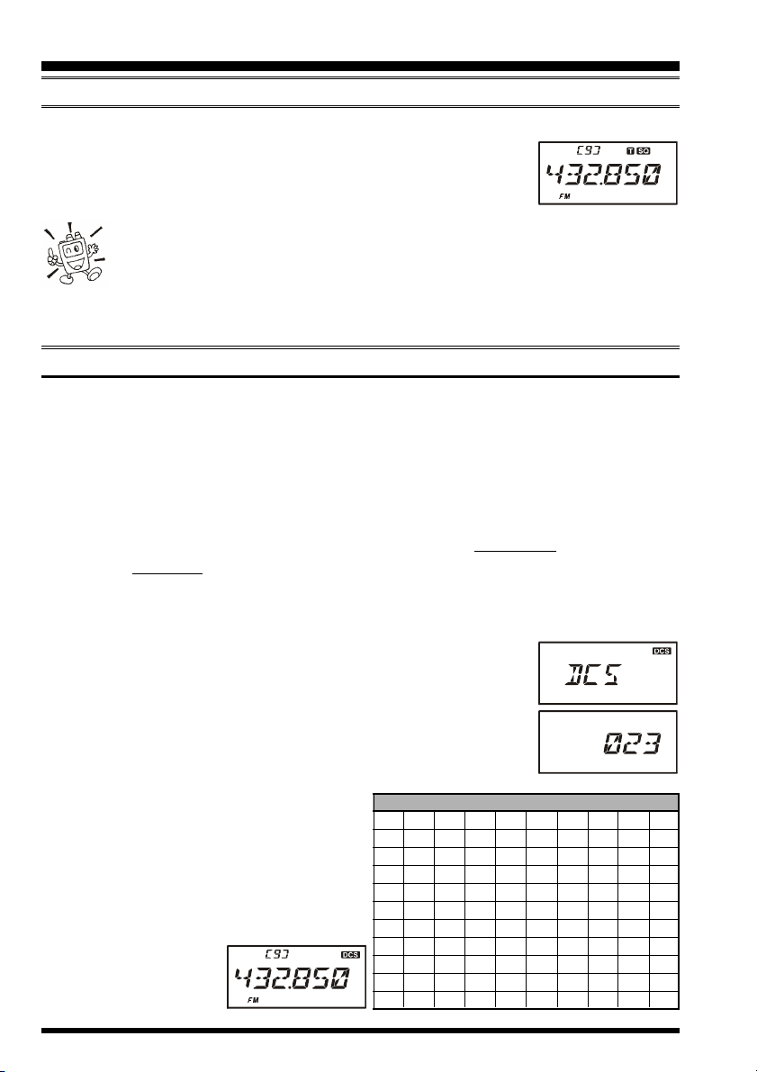
2. Rotate the DIAL knob until the “DCS” indication appears on the
display; this activates the DCS Encoder/Decoder.
3. Press the PTT key to save the new setting.
4. Press the [F/W] key, then press the [2(CODE)] key to enable
adjustment of the DCS code.
5. Rotate the DIAL knob to select the desired DCS Code (a three-
digit number). Ask the repeater owner/operator if you don’t know DCS Code; if
you are working simplex, just set up the
DCS Code to be the same as that used by
your friend(s).
6. When you have made your selection, press
the [F/W] key momentarily to save the
new settings and exit
to normal operation.
023 025 026 031 032 036 043 047 051 053
054 065 071 072 073 074 114 115 116 122
125 131 132 134 143 145 152 155 156 162
165 172 174 205 212 223 225 226 243 244
245 246 251 252 255 261 263 265 266 271
274 306 311 315 325 331 332 343 346 351
356 364 365 371 411 412 413 423 431 432
445 446 452 454 455 462 464 465 466 503
506 516 523 526 532 546 565 606 612 624
627 631 632 654 662 664 703 712 723 731
732 734 743 754 – – – – – –
DCS CODE
VX-6R OPERATING MANUAL28
 Loading...