


 Loading...
Vehicular |
|
|
|
|
|
|
|
|
|
|
VERTEX STANDARD CO., LTD. |
|||||||||||||||
|
|
|
|
|
|
|
|
|
|
4-8-8 Nakameguro, Meguro-Ku, Tokyo 153-8644, Japan |
||||||||||||||||
Cross-band Repeater |
|
|
|
|
|
|
|
|
|
|
VERTEX STANDARD |
|||||||||||||||
|
|
|
|
|
|
|
|
|
|
US Headquarters |
||||||||||||||||
|
|
|
|
|
|
|
|
|
|
|
|
|
|
|
|
|
|
|
10900 Walker Street, Cypress, CA 90630, U.S.A. |
|||||||
VXR-1000 (VHF) |
|
|
|
|
|
|
|
|
|
|
YAESU EUROPE B.V. |
|||||||||||||||
|
|
|
|
|
|
|
|
|
|
P.O. Box 75525, 1118 ZN Schiphol, The Netherlands |
||||||||||||||||
|
|
|
|
|
|
|
|
|
|
|
|
|
|
|
|
|
|
|
||||||||
|
|
|
|
|
|
|
|
|
|
|
|
|
|
|
|
|
|
|
YAESU UK LTD. |
|||||||
Service Manual |
|
|
|
|
|
|
|
|
|
|
Unit 12, Sun Valley Business Park, Winnall Close |
|||||||||||||||
|
|
|
|
|
|
|
|
|
|
Winchester, Hampshire, SO23 0LB, U.K. |
||||||||||||||||
|
|
|
|
|
|
|
|
|
|
|
|
|
|
|
|
|
|
|
||||||||
|
|
|
|
|
|
|
|
|
|
|
|
|
|
|
|
|
|
|
VERTEX STANDARD HK LTD. |
|||||||
|
|
|
|
|
|
|
|
|
|
|
|
|
|
|
|
|
|
|
Unit 5, 20/F., Seaview Centre, 139-141 Hoi Bun Road, |
|||||||
©2003 VERTEX STANDARD CO., LTD. |
E137190A |
|
|
|
|
|
|
|
|
Kwun Tong, Kowloon, Hong Kong |
||||||||||||||||
|
|
|
|
|
|
|
|
|
|
|
|
|
|
|
|
|
|
|
|
|
|
|
|
|
|
|
|
|
|
|
|
|
|
|
|
|
|
|
|
|
|
|
|
|
|
|
|
|
|
|
|
|
|
|
|
|
|
|
|
|
|
|
|
|
|
|
|
|
|
|
|
|
|
|
|
|
|
|
|
|
|
|
|
|
|
|
|
|
|
|
|
|
|
|
|
|
|
|
|
|
|
|
|
|
|
|
|
|
|
|
|
|
|
|
|
|
|
|
|
|
|
|
|
|
|
|
|
|
|
|
|
|
|
|
|
|
|
|
|
|
|
|
|
|
|
|
|
|
|
|
|
|
|
|
|
|
|
|
|
|
|
|
|
|
|
|
|
|
|
|
|
|
|
|
|
|
|
|
|
|
|
|
|
|
|
|
|
|
|
|
|
|
|
|
|
|
|
|
|
|
|
|
|
|
|
|
|
|
|
|
|
|
|
|
|
|
|
|
|
|
|
|
|
|
|
|
|
|
|
|
|
|
|
|
|
|
|
|
|
|
|
|
|
|
|
|
|
|
|
|
|
|
|
|
|
|
|
|
|
|
|
|
|
|
|
|
|
|
|
|
|
|
|
|
|
|
|
|
|
|
|
|
|
|
|
|
|
|
|
|
|
|
|
|
|
|
|
|
|
|
|
|
|
|
|
|
|
|
|
|
|
|
|
|
|
|
|
|
|
|
|
|
|
The VXR-1000 Series is designed to provide extended handheld coverage by repeating transmissions in both directions through an existing high power mobile radio.
Reliability is assured by a highly integrated surface mount circuit design and a aluminum extrusion chassis. Important channel frequency data is stored in EEPROM, and is easily programmable by dealers using a personal computer and the Vertex VPL-1 Programming Cable and CE-22 Software.
Please take a few minutes to read this manual carefully. The information presented here will allow you to derive maximum performance from your VXR-1000. After reading it, keep the manual handy for quick reference, in case questions arise later on.
We’re glad you joined the Vertex team. Call on us any time, because our business is communications. Let us help you get your message across.
Contents
Operating Manual Reprint........................ |
2 |
Specifications ............................................... |
4 |
Installations .................................................. |
5 |
Interconnection with |
|
Vertex VXSeries Transceiver ........ |
7 |
VXR-1000 Trunking Interface Manual....... |
11 |
CE-22 Programming Software .................. |
14 |
Exploded View & Miscellaneous Parts........ |
25 |
Block Diagram .............................................. |
26 |
Circuit Description ...................................... |
27 |
Alignment ...................................................... |
29 |
Repeater Cloning.......................................... |
32 |
Board Unit (Schematics, Layouts & Parts) |
|
Main Unit ............................................................... |
33 |
1

Operating Manual Reprint
CONTROLS & CONNECTORS
Front Panel
Microphone Jack
Connect the microphone plug to this jack.
CHANNEL Selector Knob
This knob selects the operating channel.
PRI Indicator
When on, “PRI” indicates that the unit is at priority count zero and will repeat all transmissions.
TX Indicator
When on, “TX” indicates that the repeater is transmitting to the handheld.
COR Indicator
This lamp blinks red when the VXR-1000 is receiving a signal from a handheld, and glows red while the VXR-1000 is receiving a subaudible tone from the handheld.
Rear Panel
EXT SP (External Speaker)
An external loudspeaker may be connected to this 2-contact, 3.5-mm mini-phone jack.
DSUB 9-Pin Accessory Connector
External TX audio line-input, PTT, external RX audio line-output, and other signals may be obtained from this connector for use with accessories.
|
Pin Assignments |
Pin 1 |
GND |
|
|
|
|
|
|
Pin 2 |
Mobile Transmit Audio |
Pin 3 |
Power Supply Control |
|
|
|
|
|
|
Pin 4 |
Mobile PTT Output |
Pin 5 |
Vcc (13.8V DC) |
|
|
|
|
|
|
Pin 6 |
Mobile Receive Audio |
Pin 7 |
Mobile COR Detect |
|
|
|
|
|
|
|
Mobile Microphone |
|
Mobile TX |
|
Pin 8 |
Pin 9 |
Detect/Mobile |
||
Audio |
||||
|
|
Microphone PTT |
||
|
|
|
Antenna Socket
The Antenna socket is a standard 50 Ω BNC antenna connector.
MBL Indicator
This lamp blinks red when the Mobile is receiving signal from repeater or base, and glows red while the Mobile is transmitting to the repeater or base.
PWR Indicator
This is the main “POWER ON” indicator for the VXR-1000.
VOLUME Knob
This knob adjusts the receiver volume.
Error Message
No Channel Data |
TX, COR, and PWR Indicators |
(Operating Channel is Vacant) |
Blink |
|
|
ARTS Out of Range |
PWR Indicator Blinks |
2

HARDWARE SETTINGS
JP1004: Controls the output impedance of the transmit audio line to the mobile radio. Short: low-Z (600 Ω); open: high-Z (4.7 kΩ) *
JP1005: Controls the maximum drive level of the transmit audio output to the mobile.
Short: low level output (0-100 mV)*; open: high level output (0-5 V).
JP1001/1002/1003:
Polarity of Power supply control. Default setting: active high (JP1003: short).
VR1001: Mobile Microphone level
VR1002: Mobile RX Audio (External Modulation level)
VR1007:Mobile TX Audio (output level)
* default setting
The VXR-1000 has a fixed 3 minute time-out timer for base to handheld transmissions. If the mobile COR is active for more than 3 minutes it will send a error blip and cease transmission until the mobile COR is inactive.
FUNCTIONAL DESCRIPTION
When the user leaves the vehicle, they activate their mobile radio via its front panel or a separate switch. When the mobile radio is receiving a signal, the VXR-1000 will begin transmitting on the hand-held’s receive frequency. The user is able to hear and respond to all radio traffic, including other hand-helds on the same frequency. The repeater jumpers and potentiometers are custom-configured for use with the particular mobile radio to which it will be connected. The CE-22 software is used to program the repeater for the required operating parameters.
Operating Manual Reprint
TRUNKING OPERATION
When the radio is connected to a trunking mobile you wish to access the system from your handheld radio, key the handheld briefly then release the PTT key. The radio will attempt to acquire a voice channel on the trunking system by keying the mobile for 200 mS and monitoring the “on-air detect” line from the mobile. If the VXR-1000 does not see the radio transmit at all (system is busy), it will send a low tone to the handheld to alert you that the system is busy. The radio will automatically retry every 5 seconds and send a “busy” tone to the handheld with each unsuccessful attempt, to indicate progress of the call attempt. If unsuccessful after 30 seconds, the radio will transmit an “intercept” tone to alert the handheld that the call attempt failed.
When the VXR-1000 detects that the mobile is transmitting, it will continue to monitor the “onair detect” line until the transmitter remains keyed for at least 250 mS to determine if the radio is merely handshaking or retrying. After successful acquisition of a voice channel, it will continue to hold the mobile’s PTT active for 2 seconds and transmit a “go-ahead” blip to the handheld. You may then key their handheld to speak on the voice channel. If you do not key up within the 2-second period, the radio will unkey the mobile and send the “intercept” tone, as before.
3
Specifications
GENERAL
Frequency Range: |
150 - 174 MHz |
|
(Receive frequencies within a ±5 MHz spread over the range 150 - 174 |
MHz) |
|
Number of Channels: |
16 Channels |
Channel Spacing: |
12.5/25 kHz |
Supply Voltage: |
13.8V DC, negative ground |
Ambient Temperature Range: |
−30 °C to +60 °C |
Frequency Stability: |
±2.5 ppm |
RF Input-Output Impedance: |
50 Ω |
Audio Output Impedance: |
8 Ω |
Case Size (WHD): |
111 × 25.4 × 136 mm (4.4” × 1” × 5.4”) |
Weight: |
400 g (0.9 lb.) |
RECEIVER
Circuit Type: |
Double Conversion Superheterodyne |
Sensitivity: |
EIA 12dB SINAD 0.30 µV |
20 dB Quieting: |
0.40 µV |
Squelch Threshold: |
0.2 µV to 2 µV |
Adjacent Channel Selectivity: |
60 dB |
Intermodulation Rejection: |
60 dB |
Spurious and Image Rejection: 60 dB
Conducted Spurious Emissions: −57 dBm
Audio Output: |
1 W into 8 Ω w/<5% THD |
Hum and Noise: |
−40 dB |
TRANSMITTER
Power Output: |
5.0/2.5/1.0/0.5 W |
Modulation: |
16K0F3E /11K0F3E |
Maximum Deviation: |
±5 kHz/2.5 kHz |
Conducted Spurious Emissions: −60 dBc |
|
FM Hum and Noise: |
−40 dB |
Specifications may be subject to change without notice or obligation.
4
The VXR-1000 must only be installed in vehicles having a negative ground electrical system. Mount the transceiver where the Indicators, controls, and microphone are easily accessible, using the supplied mounting bracket. The VXR1000 may be installed in any position, but should not be positioned near a heating vent nor anywhere where it might interfere with driving (either visually or mechanically).
VXR-1000 Installation
Choose a mounting location with sufficient clearance for the VXR-1000, plus space for ventilation around the cooling fan and above and below the VXR-1000. Using the mounting bracket as a template for the mounting holes, use a 4.8 mm (3/16") bit to drill the mounting holes, and secure the mounting bracket with the supplied screws, washers, and nuts (see diagram).
Position the VXR-1000 in the bracket so that the holes in the side are aligned with those in the bracket, and bolt the VXR-1000 into place using the supplied short screws and flat washers.
Installations
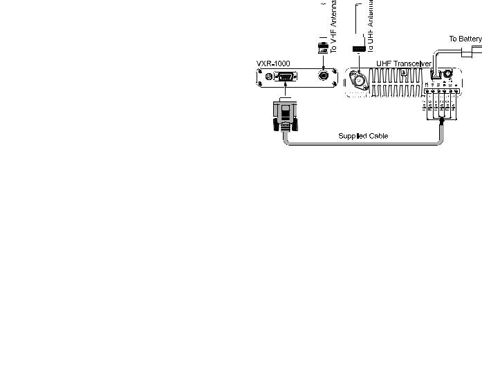
VXR-1000 Connections
The VXR-1000 provides a convenient rear-pan- el Accessory Connector for easy connections to your transceiver. The connections to this jack are in accordance with a standard adopted by many commercial radio. However, we recommend that you verify the connections to any cable you already own by comparison to the pictorial below.
5

Installations
VXR-1000 Connections
Pin 1: GND
Signal Ground
Pin 2: Mobile Transmit Audio
Receive audio output from the VXR-1000, passed to the MIC jack of the mobile transceiver.
Output impedance can be changed via jumper JP1004. open: 4.7 kΩ, short: 600 Ω (default: open).
Output level can be changed via jumper JP1005 (range) and VR1007 (value).
open: -15 ~ +7 dBm, short: -40 ~ -15 dBm (default: short). Frequency response (pre-emphasis on/off) can be changed via CE-22 software (default: off).
Pin 3: Power Supply Control
The polarity of the “Power Supply Control” line can be changed via jumpers JP1001/1002/1003.
high: 3 ~ 16 V
JP1001 |
J1002 |
J1003 |
Function |
|
|
|
|
|
|
short |
short |
open |
VXR-1000 turns on when |
|
this pin connects to ground. |
||||
|
|
|
||
|
|
|
|
|
short |
open |
short |
VXR-1000 turns off when |
|
this pin connects to ground. |
||||
|
|
|
||
|
|
|
|
|
open |
short |
open |
VXR-1000 turns off when |
|
this pin is “high” level. |
||||
|
|
|
||
open |
open |
short |
VXR-1000 turn on when this |
|
pin is “high” level. |
||||
|
|
|
||
|
|
|
|
Pin 4: Mobile PTT Output
This pin controls the mobile transceiver’s TX/RX status. This pin is an open-collector, “active-low” circuit. When this pin closes to ground,
the mobile transceiver is switched into the TRANSMIT mode. Maximum current: <20 mA.
Pin 5: Vcc (13.8 V)
This pin is the DC power supply connection for the VXR-1000.
Maximum current: 2A.
Pin 6: Mobile Receive Audio
Receiver audio input to the VXR-1000 from the mobile transceiver.
Input impedance: 100 kΩ
The input level can be changed via CE-22 (range) and VR1002 (value).
CE-22 EXT MOD level “HIGH”: –18 dBm ~ –2 dBm CE-22 EXT MOD level “LOW”: –36 dBm ~ –18 dBm Frequency response (de-emphasis on/off) can be
changed via CE-22 (default: off).
Pin 7: Mobile COR Detect
Squelch control input (including the effect of a CTCSS or DCS detected tone) or audio mute line, also known as a “BUSY” line.
When this pin is at “high” level (mobile radio Squelch open), the VXR-1000 is commanded into the TRANSMIT mode.
Squelch open: 3 V, Squelch closed: 0 V. Squelch open: >3 V, Squelch closed: 0 V.
This input level can be switched between “Squelch open” and “Squelch closed” when this pin is at “high” level via CE-22.
Impedance: 1 MΩ.
The Squelch Threshold level can be changed by adjustment of VR1003.
Pin 8: Mobile Microphone Audio
Mobile microphone audio input. This is the same audio which is being sent to the mobile radio’s Mic Amp circuit (i.e. the microphone’s audio is “split” between the mobile radio and the VXR-1000)
Input impedance: 100 kΩ
The input level to the mobile transceiver can be changed via CE-22 (range) and VR1001 (value).
CE-22 EXT MIC level “HIGH”: –18 dBm ~ 0 dBm CE-22 EXT MIC level “LOW”: –44 dBm ~ –18 dBm
Pin 9: Mobile TX detect/Mobile Microphone PTT
Mobile Tx/Rx control input.
This input function can be switched between “Mobile MIC PTT” input and “Mobile Tx Detect” line input via CE-22.
This input level can be switched between “Tx” and “Rx” when this pin is at “high” level via CE-22. Input impedance: 10 kΩ.
Note:, When the VXR-1000 is used in a Trunking system, the “Mobile TX Detect” input signal must be received from the mobile transceiver when connected to the Trunking system (the VXR-1000 checks this pin’s level to confirm successful connection to the trunking system). When this pin is at “high” level (>3 V), the VXR-1000 is commanded into the TRANSMIT mode. When a successful “handshake” occurs with the Trunking system, this line goes “low” and the VXR-1000 is released into the RECEIVE mode.
6
Interconnection with Vertex VXSeries Transceivers
This document outlines the interconnections and hardware settings required for interface of the Vertex VXR-1000 Compact Mobile Repeater to the Vertex VXseries of mobile transceivers.
1. Interconnections to Mobile Transceivers
The chart below shows the interconnections between J1004 on the VXR-1000 and the corresponding interface jacks on the compatible mobile transceivers.
VXR-1000 DSUP 9-pin Accessory Connector |
FTL-7011 |
VX-2000 |
VX-3000 |
|
||||
Pin 1 |
GND |
Pin 8 of J2006 |
GND |
Pin 5 of J1003 |
GND |
Pin 5 of J1004 |
|
GND |
|
|
|
|
|
|
|
|
|
Pin 2 |
Mobile Transmit Audio |
Pin 4 of J2006 |
MIC IN |
Pin 3 of J1003 |
MOD IN |
Pin 3 of J1004 |
|
EXM |
|
|
|
|
|
|
|
|
|
Pin 3 |
Power Supply Control |
Pin 12 of J2006 |
13.8V SWED |
Pin 8 of J1003 |
+5V |
Pin 8 of J1004 |
|
13 SWD |
|
|
|
|
|
|
|
|
|
Pin 4 |
Mobile PTT Output |
Pin 1 of J2006 |
PTT |
Pin 7 of J1003 |
PTT |
Pin 7 of J1004 |
|
PTT |
|
|
|
|
|
|
|
|
|
Pin 5 |
Vcc (13.8 V) |
Pin 9 of J2006 |
13.8V |
TP1003 |
13.8V |
13.8 V IN |
|
13.8V |
|
|
|
|
|
|
|
|
|
Pin 6 |
Mobile Receive Audio |
Pin 3 of J2001 |
DET IN |
Pin 2 of J1003 |
DISC OUT |
Pin 2 of J1004 |
|
LINE |
|
|
|
|
|
|
|
|
|
Pin 7 |
Mobile COR Detect (Note 1) |
Pin 1 of J2001 |
SQ S G |
Pin 1 of J1003 |
SQ |
Pin 1 of J1004 |
|
SQ |
(or Base of Q2005) |
(AF MUTE) |
(or Base of Q1008) |
(AF MUTE) |
|
||||
|
|
|
|
|
||||
|
|
|
|
|
|
|
|
|
Pin 8 |
Mobile Microphone Audio |
No Connection |
− |
No Connection |
− |
No Connection |
|
− |
|
|
|
|
|
|
|
|
|
Pin 9 |
Mobile TX detect/Mobile Mic. PTT (Note 2) |
Pin 5 of J2005 |
RX/TX |
TP1013 |
TX 9V |
No Connection |
|
− |
|
|
|
|
|
|
|
|
|
Shield |
GND |
GND |
− |
GND |
− |
GND |
|
− |
|
|
|
|
|
|
|
|
|
Note 1: The Mobile COR Detect line may be |
Note 2: When the mobile transceiver is not |
connected, inside the mobile trans- |
used in a trunking environment, the |
ceiver, to either pointshown (e.g. for |
“Mobile TX Detect” function is not |
the VX-2000, either to Pin 1 of J1003 |
used. |
(SQ) or to the Base of Q1008 )AF |
|
MUTE). See Section 6 of this document |
|
for information regarding the Mobile |
|
COR Detect connection in the VX- |
|
3000. |
|
7
Interconnection with Vertex VXSeries Transceivers
2. FTL-7011
(HARDWARE/SOFTWARE SETTINGS FOR VXR-1000)
2-1: VXR-1000 Internal Jumpers
POWER SUPPLY CONTROL: JP1001 Open
JP1002 Open
JP1003 Jumper
VXR-1000 OUTPUT: JP1004 Open
JP1005 Jumper
2-2: CE-22 “Common Data” (F2) Settings
Use the “CE22 /P” option when starting the CE-22 Software.
PTT1 State: High (set to “Low” if connecting to the MUTE connection at the base of Q2005)
PTT2 State: Low (if no connection is made to Pin 9 of J1004, set to “High”)
Pre-Emphasis: Off
De-Emphasis: On EXT MOD Level: Low EXT MOD Level: Low
3. VX-2000
(HARDWARE/SOFTWARE SETTINGS FOR VXR-1000)
3-1: VX-2000 Internal Jumpers
These jumpers configure the interconnec-
tions made via the D-sub 9-pin connector
on the rear of the VX-2000.
JP1002 Open
JP1003 Jumper
JP1004 Jumper
JP1005 Open
3-2: VXR-1000 Internal Jumpers
POWER SUPPLY CONTROL: |
JP1001 |
Open |
|
JP1002 |
Open |
|
JP1003 |
Jumper |
VXR-1000 OUTPUT: |
JP1004 |
Open |
|
JP1005 |
Jumper |
3-3: CE-22 “Common Data” (F2) Settings
Use the “CE22 /P” option when starting the
CE-22 Software.
PTT1 State: High
PTT2 State: High
Pre-emphasis: Off
De-Emphasis: On
EXT MIC Level: Low
EXT MOD Level: Low
4. VX-3000
(HARDWARE/SOFTWARE SETTINGS FOR VXR-1000)
4-1: VX-3000 Internal Jumpers
These jumpers configure the interconnections made via the D-sub 9-pin connector on the rear of the VX-3000.
Note that the connections for the VX-3000L (Low-Band) are different from those for the VX-3000U.
VX-3000L JP1002 Open JP1003 Jumper JP1004 Open JP1005 Jumper JP1009 Open JP1010 Jumper
VX-3000U JP1003 Open (RXD) JP1004 Jumper (EXRA) JP1005 Open (TXD) JP1006 Jumper (EXM) JP1009 Open
JP1010 Jumper
Connect a 10 kΩ resistor between Pin 1 and Pin 8 at J1004 of the VX-3000; this is a pullup resistor for the Squelch line.
4-2: VX-3000 Software Settings in CE-19 for PTT and MIC
These settings must be set appropriately within CE19 in order for the VXR-1000 to work correctly with the VX-3000.
8
Interconnection with Vertex VXSeries Transceivers
[COMMON]
[ MISCELLANEOUS]
[ EXTERNAL PTT]
Set to (Mic & Option)
[GROUP]
[CHANNEL ALLOCATIONS]
[GROUP]
[EXTERNAL MIC]
Set to (Enabled)
4-3: VXR-1000 Internal Jumpers
POWER SUPPLY CONTROL: |
JP1001 |
Open |
|
JP1002 |
Open |
|
JP1003 |
Jumper |
VXR-1000 OUTPUT: |
JP1004 |
Open |
|
JP1005 |
Jumper |
4-4: CE-22 “Common Data” (F2) Settings
Use the “CE22 /P” option when starting the
CE-22 Software.
PTT1 State: Low
PTT2 State: Low
(set to “High” when con-
necting to Pin 9 of J1004)
Pre-emphasis: Off
De-emphasis: On
EXT MIC Level: Low
EXT MOD Level: Low
5.Alignment
5-1: VXR-1000 Deviation Setting
On the connected mobile transceiver, receive a signal from an external signal source with 1 kHz modulation frequency and deviation level of ±3.0 kHz (±1.5 kHz for the “Narrow” mode).
This signal, when passed from the connected mobile transceiver to the VXR-1000, should produced a transmitted signal from the VXR-1000 with 1 kHz deviation at not less than ±3.0 kHz (±1.5 kHz for the “Narrow” mode).
If the deviation level from the VXR-1000 is not correct, adjust VR1002 (inside the VXR-
1000) for an output deviation of ±3.0 kHz (±1.5 kHz in the “Narrow” mode).
5-2: VXR-1000 Receiver Output Level Setting
When the VXR-1000 receives a signal from an external signal source (on the uplink frequency used by the portable transceiver) modulated at 1 kHz at a level of ±3.0 kHz (±1.5 kHz in the “Narrow” mode”), the output passed to the connected mobile transceiver should produce a transmitted output signal from the mobile at a level of ±3.0 kHz (±1.5 kHz in the “Narrow” mode”).
If the output level to the mobile does not produce correct deviation from the mobile, adjust VR1007 (inside the VXR-1000) so that the transmitted output from the mobile is modulated at a level of ±3.0 kHz (±1.5 kHz in the “Narrow” mode”).
6. Trunking System configuration
All trunking parameters depend on the configuration of the individual trunking system in which the connected mobile transceiver is used. Please consult the CE22 programming instructions, and the separate “VX1000R Trunking Interface Manual,” for information about the software and other settings for the VXR-1000 when integrated into a trunking environment.
7. Miscellaneous
In order to improve the audio muting performance of the VX-3000, a minor circuit change was adopted from Production Lot #03 (VX-3000L/U) and 04 (VX-3000V), and this change was reflected in CE-19 software version 1.16. This change affects the connection point for the Squelch (Mobile COR Detect) line, and the connection point is identified as “AF MUTE•in the various documentation for the VX-3000.
The configuration version can be identified by looking for the presence of a jumper connection at jumper pad JP1002 in the VX3000U, or JP1016 in the VX-3000L. The connections for the Mobile COR Detect line should be made as follows:
9
Interconnection with Vertex VXSeries Transceivers
VX-3000U
If JP1002 is not jumpered, connect this line to Pin 8 of Q1043.
If JP1002 is jumpered, connect the Mobile COR Detect line to JP1002.
VX-3000L
If JP1016 is not jumpered, connect this line to Pin 8 of Q1043.
If JP1016 is jumpered, connect the Mobile COR Detect line to JP1016.
10
VXR-1000 Trunking Interface Manual
This document outlines the interconnections and hardware settings required for interface of the Vertex VXR-1000 Compact Mobile Repeater to the Vertex VXseries of mobile transceivers in a trunked environment (using the Vertex VXTrunk System).
The illustration below outlines the basic configuration of a VX-Trunk system, using the VXR1000 as a range extender for a portable transceiver.
1. EQUIPMENT REQUIRED
2-1-2: VXR-1000 Interconnections to FTL-7011
VXR-1000 DSUB 9-pin |
FTL-7011 |
|
Accessory Connector |
||
|
||
Pin 1: GND |
Pin 8 of J2006 |
|
Pin 2: Mobile Transmit Audio |
Pin 4 of J2006 |
|
Pin 3: Power Supply Control |
Pin 12 of J2006 |
|
Pin 4: Mobile PTT Output |
Pin 1 of J2006 |
|
Pin 5: Vcc (13.8 V) |
Pin 9 of J2006 |
|
Pin 6: Mobile Receive Audio |
Pin 3 of J2001 |
|
Pin 7: Mobile COR Detect |
Pin 1 of J2001 |
|
Pin 8: Mobile Microphone Audio |
No Connection |
|
Pin 9: Mobile TX detect/Mobile Mic. PTT |
No Connection |
2-2: Interconnections to VX-2000/Configuration
2-2-1: VXR-1000 Internal Jumpers JP1004 Open JP1005 Jumpered
2-2-2: VX-2000 Internal Jumpers
JP1002 Jumpered
JP1003 Open
JP1004 Open
JP1005 Open
JP1007 Open
JP1008 Open
JP1009 Open
Connect a jumper from Pin 3 of J1003 to the shared side ofJP1009/Pin 4 of J1007.
Portable Transceiver: Must have a DTMF Encoder installed.
Mobile Transceiver: Must be configured for operation within VXTrunk System. Compatible models include FTL7011, VX-2000, and VX3000. Please refer to the VX-Trunk System documentation for configuration details for the mobile transceiver.
2. INTERCONNECTIONS FROM VXR-1000 TO
MOBILE TRANSCEIVERS
2-1: Interconnections to FTL-7011/Configuration
2-1-1: VXR-1000 Internal Jumpers
JP1004 Open JP1005 Jumpered
Remove R1010
Connect a jumper from Pin 7 of J1003 to the shared side of JP1008/Pin 1 of J1007.
Connect a jumper between Pin 4 of J1003 and Pin 6 of the connector of the VTM-20 Trunking Controller board.
2-2-3: VXR-1000 Interconnections to VX-2000
The chart below describes the individual wire functions for the cable connected between the D-Sub 9-pin connectors on the VXR-1000 (J1004) and VX-2000 (J1003).
VXR-1000 DSUB 9-pin |
VX-2000 |
|
Accessory Connector |
||
|
||
Pin 1: GND |
Pin 5 of J1003 |
|
Pin 2: Mobile Transmit Audio |
Pin 3 of 1003 |
|
Pin 3: Power Supply Control |
Pin 8 of J1003 |
|
Pin 4: Mobile PTT Output |
Pin 7 of J1003 |
|
Pin 5: Vcc (13.8 V) |
Switched |
|
|
13.8VDC |
|
|
output from the |
|
|
Power Switch |
|
Pin 6: Mobile Receive Audio |
Pin 2 of J1003 |
|
Pin 7: Mobile COR Detect |
Pin 4 of J1003 |
|
Pin 8: Mobile Microphone Audio |
No Connection |
|
Pin 9: Mobile TX detect/Mobile Mic. PTT |
No Connection |
11
VXR-1000 Trunking Interface Manual
2-3: Interconnections to VX-3000/Configuration
2-3-1: VXR-1000 Internal Jumpers *JP1004 Open *JP1005 Jumpered
2-3-2: VX-3000 Internal Jumpers
*JP1003 Open
*JP1004 Jumpered
*JP1005 Open
*JP1006 Open
*JP1007 Open
*JP1008 Open
*Connect a jumper between the shared side of JP1006/JP1006 and Pin 7 of J1003.
*Connect a jumper between the shared side of JP1007/JP1008 and Pin 2 of J1005.
2-3-3: VXR-1000 Interconnections to VX-3000
The chart below describes the individual wire functions for the cable connected between the D-Sub 9-pin connectors on the VXR-1000 (J1004) and VX-3000 (J1004).
VXR-1000 DSUB 9-pin |
VX-3000 |
|
Accessory Connector |
||
|
||
Pin 1: GND |
Pin 5 of J1004 |
|
Pin 2: Mobile Transmit Audio |
Pin 3 of 1004 |
|
Pin 3: Power Supply Control |
Pin 8 of J1004 |
|
Pin 4: Mobile PTT Output |
Pin 7 of J1004 |
|
Pin 5: Vcc (13.8 V) |
Switched |
|
|
13.8VDC |
|
|
output from the |
|
|
Power Switch |
|
Pin 6: Mobile Receive Audio |
Pin 2 of J1004 |
|
Pin 7: Mobile COR Detect |
Pin 4 of J1004 |
|
Pin 8: Mobile Microphone Audio |
No Connection |
|
Pin 9: Mobile TX detect/Mobile Mic. PTT |
No Connection |
3. VXR-1000 CONFIGURATION
For operation in a VX-Trunk II environment, note the following setup tips regarding the VXR-1000 (set via the CE-22 software):
The VXR-1000's "Pri Timer" option must be set to a non-zero value by CE-22).
In CE-22, set the TRUNKING mode to OFF (for VX-Trunk II only; for other Trunking systems like LTR, this parameter must be set to ON).
Set PTT1 to HIGH.
Other parameters such as Master/Slave and Sub_Audio may be set via CE-22 per the customer's operating requirements.
4. VX-TRUNK SYSTEM OPERATING
EXAMPLE
4-1: Making a Call from the Portable
1.Press the portable's PTT key for longer than the "Sampling Time" of the VXR-1000, so as to ensure that the VXR-1000 receives the portable's signal, then press "3 *" while transmitting to connect to the VX-Trunk II system.
2.When the "3 *" is completed, immediately release the portable's PTT key, so as to return the portable to the receive mode.
3.If the VX-Trunk system receives the connection command, a double "beep" will be heard from the portable's speaker.
4.Press the portable's PTT key for longer than the "Sampling Time" of the VXR-1000, so as to ensure that the VXR-1000 receives the portable's signal, and enter the other unit's 5-digit subscriber number via the portable's DTMF pad. Now release the portable's PTT key to return the portable to the receive mode.
5.When the subscriber number is successfully received by the VX-Trunk II system, and a connection thereby initiated, the VX-Trunk II system will respond, and a double "beep" will be heard from the speaker of the portable.
4-2: Receiving a Call at the Portable
1.When the mobile connected to the VXR-1000 receives a connection request from the VXTrunk II system, it relays a "connection tone" to the portable. When this happens, press the PTT key on the portable.
2.Hold in the PTT key on the portable longer than the "Sampling Time" programmed for the VXR-1000, then press the DTMF "*" key. After pressing the "*" key, release the PTT key on the portable.
3.When the VX-Trunk II system receives the "*" response from the portable, it will respond, and a double "beep" will be heard from the speaker of the portable.
4-3: Terminating a Call from the Portable
1.Press the portable's PTT key.
2.Hold the portable's PTT key for longer than the "Sampling Time" of the VXR-1000, then press the "#" key. The call will now be terminated, and you may release the portable's PTT key.
12
VXR-1000 Trunking Interface Manual
5. NOTES RE TRUNKING OPERATION
5-1:
The VX-Trunk II system operates in a full duplex mode.
In this environment, while a call is in progress, the connected mobile passes the received audio through to the VXR-1000 for re-transmis- sion to the portable. In order for the portable to be able to "capture" the VXR-1000 to make a transmission back to the other party, the VXR-1000 must be set, via the CE-22 software, for a "Priority Timer" setting (Pri Timer) which is not zero. A very short time will allow quick
interruption, but the incoming message from the VXR-1000 to the portable may sound "choppy" due to the frequent interrupts.
When the portable transmits longer than the "Priority Timer" setting, the VXR-1000 will interrupt its transmission, and the VXR-1000 will instantly switch to the "receive" mode on the portable's transmitting frequency.
5-2: VXR-1000 Local Microphone
In order to facilitate the above sampling feature, it is not possible to use a "Local" mic (a DTMF microphone attached to the VXR-1000) for access to the VX-Trunk II system.
13
CE-22 Program Software
The Vertex CE-22 program is a software package which controls the VXR-1000's "Clone Edit" feature. This manual outlines the installation and use of the CE-22 software when used with the VXR-1000.
1. CE-22 Installation
and Operating Modes
The Vertex CE-22 program is an integrated software package designed to work with IBM PC, XT, AT, or compatible computers. In order for CE-22 to run properly, your computer must run DOS v3.0 (or a later version).
1-1: CE-22 Installation
There is no installation software included with your distribution diskette.
Use standard DOS procedures to install the software on your hard drive.
For example, let us create a directory named "Vertex" into which we shall install the CE22 software. First, make a copy of the distribution diskette, then use the archive copy for the installation from (floppy) Drive A:
c:\ mkdir vertex [ENTER] c:\ cd\vertex [ENTER]
c:\vertex copy a:*.* [ENTER]
The files on the archive floppy disk will now be copied to your hard drive into the new "vertex" directory.
1-2: Starting CE-22
Before starting the CE-22 program, connect the VPL-1 Cloning Cable between your computer's COM port and the VXR-1000's MIC jack.
Connecting the VPL-1 cable automatically initiates the "CLONE" (programming) mode, and the PWR LED will blink while the CLONE mode is active.
If your computer has more than one COM port, you may select the COM port to be used via the "Common Data" window (accessed by pressing F2 after CE-22 is started). Either COM1 or COM2 may be utilized.
To start CE-22, be sure your computer screen is displaying the DOS prompt. The procedure thereafter is: c:\ ce22 [ENTER]
The CE-22 program will now start. After five seconds in an initial Program Identification screen, the software will automatically switch to the main Channel Editing Screen.
1-3: Startup Options
Two mode options for CE-22 are available.
The standard ce22 command allows all nor- mally-required channel data entry parameters to be entered and/or edited. Additionally, the COM port line in the "Common Data" window may also be changed. However, other "Common Data" parameters cannot be changed, although they are visible in the window.
The alternative ce22 /p option allows editing of the other parameters in the "Common Data" window. While changes to these parameters are not normally required, major system changes may necessitate modification of one or more "Common Data" items. If this is the case, type ce22 /p [ENTER] instead of (only) ce22 [ENTER] when starting the program.
2. Sending/Downloading Data
from the VXR-1000
2-1: Reading Data from VXR-1000
When you start up CE-22, it is often useful to download the current channel information from the VXR-1000 for archive purposes.
To do this, press F5. The current data will be read by the computer, and the data will appear on the screen. If you wish to save this data to disk, press F4 and assign a file name into which the archive data will be saved.
2-2: Loading Data to VXR-1000
When all channel data has been successfully set up, press F6 to send the channel data to the VXR-1000.
2-3: Saving Data to Disk
Channel programming data may be saved to your computer's hard drive, or to a flop-
14
py diskette, by use of the F4 command. You will be prompted to define a file name to be used. Standard DOS file name specifications should be used (e.g. no more than eight characters in the file name).
If you wish to create a separate sub-directo- ry (so as to store files for different customers in different sub-directories, for example), press [Tab], then press [F3], to activate the [Mk Dir] (Make Directory) function. You can then type in the name you wish to use for this sub-directory, then continue with the file storage process.
2-4: Printing Hard Copy
To print a copy of the currently-displayed channel data file, press [F7] when all programming steps have been completed. This allows you to attach a copy of the programming information to the programming work order, for the convenience of the customer.
3. Programming Navigation/
Use of SPACE Key
When CE-22 is initially started with a new VXR-1000, only CHANNEL 1 will be showing.
Use the UP and DOWN keys to navigate to different channel numbers. Use the LEFT and RIGHT keys to navigate between the various columns of a particular channel programming line. Beginning in Section 4 of this manual, we will only discuss a single line of channel programming data, as each line of channel programming data is identical (except for the fact that CHANNEL 1's data cannot be hidden).
3-1: Hiding/Un-hiding Channel Data using SPACE Bar
The SPACE bar is used in many programming steps to activate or de-activate a particular function.
If the cursor is on the channel number column, however, pressing the SPACE bar will toggle between hiding of that channel number's data and re-activating that channel number's data. CHANNEL 1's data, however, cannot be hidden.
CE-22 Program Software
A channel number on which data has been hidden will display "-- --" in place of the field entries. On the VXR-1000, if you select a "hidden" channel, three indicators will blink to alert you to this fact.
If you make a change to the programming of a "hidden" channel at a later time, the channel will automatically be re-activated (removed from "hidden" status). You will need to return to the Rx Freq field in order to re-hide it.
3-2: Primary Use for SPACE Bar
In many programming steps, such as CTCSS or DCS tone/code entry, an initial press of the SPACE bar will activate the parameter (turn it on) or de-activate the parameter (turn it off). In each such step, you will be prompted in the upper-right-hand window as to additional steps to be taken to secure the final value for the parameter you are currently setting.
In programming steps where a numerical value is required, press the [Space] bar to increase the value, or [Back Space] to decrease the value.
4. Channel Frequency Programming
4-1: Rx Freq.
(Edit Receive (or Simplex) Frequency)
Use the 0 - 9 keys to enter the desired channel frequency directly, and press [ENTER]. The frequency entered will be adjusted automatically if it does not conform to the "CHANNEL STEP" parameter, and will be adjusted to the nearest "valid" step; the frequency will also appear in the Tx Freq. field (next step) automatically, to simplify entry if the current channel is to be used on Simplex. You do not need to enter all eight digits of the frequency; empty digits to the right will be set to "0" when you press [ENTER]. Pressing [.] ("period") after several digits forces those digits to be "MHz" digits. If you press [.] before entering any digits, only the "kHz" digits will be changed.
Pressing only the SPACE bar, without entering any frequency digits, toggles the data for the entire channel between "hidden" and
15
Loading...