


144/430 MHz |
VERTEX STANDARD CO., LTD. |
|
Dual-Band FM Transceiver |
4-8-8 Nakameguro, Meguro-Ku, Tokyo 153-8644, Japan |
|
VERTEXSTANDARD |
||
with GPS |
||
US Headquarters |
||
|
10900 Walker Street, Cypress, CA 90630, U.S.A. |
|
VX-8GR |
YAESU UK LTD. |
|
Unit 12, Sun Valley Business Park, Winnall Close |
||
|
Winchester, Hampshire, SO23 0LB, U.K. |
|
Technical Supplement |
VERTEX STANDARD HK LTD. |
|
Unit 5, 20/F., Seaview Centre, 139-141 Hoi Bun Road, |
||
|
||
|
Kwun Tong, Kowloon, Hong Kong |
|
©2010 VERTEX STANDARD CO., LTD. Printed in Japan. |
VERTEX STANDARD (AUSTRALIA) PTY., LTD. |
|
Normanby Business Park, Unit 14/45 Normanby Road |
||
|
||
EH041M90A |
Notting Hill 3168, Victoria, Australia |
|
|
|
Introduction
This manual provides the technical information necessary for servicing the VX-8GR 144/430 MHz Dual-Band FM Transceiver.
Servicing this equipment requires expertise in handing surface-mount chip components. Attempts by non-qualified persons to service this equipment may result in permanent damage not covered by the warranty, and may be illegal in some countries.
Two PCB layout diagrams provided for each double-sided board in this transceiver. Each side of the board is referred to by the type of the majority of components installed on that side ("Side A" or "Side B"). In most cases one side has only chip components, and the other has either a mixture of both chip and leaded components (trimmers, coils, electrolytic capacitors, ICs, etc.), or leaded components only.
While we believe the information in this manual to be correct, VERTEX STANDARD assumes no liability for damage that may occur as a result of typographical or other errors that may be present. Your cooperation in pointing out any inconsistencies in the technical information would be appreciated.
Important Note
1)This transceiver was assembled using Pb (lead) free solder, based on the RoHS specification.
Only lead-free solder (Alloy Composition: Sn-3.0Ag-0.5Cu) should be used for repairs performed on this apparatus. The solder stated above utilizes the alloy composition required for compliance with the lead-free specification, and any solder with the above alloy composition may be used.
2)Risk of explosion if battery is replaced by an incorrect type. Dispose of used batteries according to the instructions.
|
Contents |
Specification ........................................................................................................................................................................... |
2 |
Exploded View & Miscellaneous Parts ............................................................................................................................. |
4 |
Block Diagram ....................................................................................................................................................................... |
5 |
Alignment ............................................................................................................................................................................... |
7 |
Board Unit (Schematics, Layouts & Parts) |
|
RF Unit Circuit Diagram ............................................................................................................................................... |
19 |
RF Unit Parts Layout ..................................................................................................................................................... |
20 |
RF Unit Parts List ........................................................................................................................................................... |
21 |
CNTL Unit Circuit Diagram ......................................................................................................................................... |
37 |
CNTL Unit Parts Layout ............................................................................................................................................... |
38 |
CNTL Unit Parts List ..................................................................................................................................................... |
39 |
CABLE Unit Circuit Diagram ....................................................................................................................................... |
49 |
CABLE Unit Parts Layout ............................................................................................................................................. |
49 |
CONNECT Unit Circuit Diagram ................................................................................................................................ |
50 |
CONNECT Unit Parts Layout ...................................................................................................................................... |
50 |
MAIN VCO Unit Circuit Diagram ............................................................................................................................... |
51 |
MAIN VCO Unit Parts Layout ..................................................................................................................................... |
51 |
MAIN VCO Unit Parts List ........................................................................................................................................... |
53 |
SUB VCO Unit Circuit Diagram ................................................................................................................................... |
55 |
SUB VCO Unit Parts Layout ........................................................................................................................................ |
55 |
SUB VCO Unit Parts List .............................................................................................................................................. |
57 |
VX-8GR Technical Supplement |
1 |

Specifications
GENERAL |
A (Main) Band RX: |
108-137 MHz(AirBand) |
FrequencyRanges: |
||
|
|
137-174MHz(144MHzHAM) |
|
|
174-222MHz(VHF-TV) |
|
|
222-420MHz(General1) |
|
|
420-470MHz(430MHzHAM) |
|
|
470-800MHz(UHF-TV,CellularBlocked) |
|
|
800-999.90MHz(General2,CellularBlocked) |
|
B (Sub) Band RX: |
108-137 MHz(AirBand) |
|
|
137-174MHz(144MHzHAM) |
|
|
174-222MHz(VHF-TV) |
|
|
222-420MHz(General1) |
|
|
420-470MHz(430MHzHAM) |
|
|
470-580MHz(UHF-TV) |
|
TX: |
144-146MHzor144-148MHz |
|
|
430-440MHzor430-450MHz |
Channel Steps: |
5/6.25/8.33/10/12.5/15/20/25/50/100kHz |
|
EmissionType: |
F1D,F2A,F2D,F3E |
|
FrequencyStability: |
±5 ppm (–10 °C to +60 °C [+14 °F to +140 °F]) |
|
Repeater Shift: |
±600kHz(144MHz),±1.6/5.0/7.6MHz(430MHz) |
|
AntennaImpedance: |
50 Ohms |
|
SupplyVoltage: |
Nominal: 7.4 V DC (Negative Ground) |
|
|
Operating: 4-14 V DC (Negative Ground, EXT DC jack) |
|
|
Operating with Charging: 11-16 V DC (Negative Ground, EXT DC jack) |
|
CurrentConsumption: 200 mA (Mono Band Receive) |
||
(@7.4VDC,approx.) |
240 mA (Dual Band Receive) |
|
|
85 mA (Mono Band Receive, Standby, Saver Off) |
|
|
120 mA (Dual Band Receive, Standby, Saver Off) |
|
|
35 mA (Mono Band Receive, Standby, Saver On “Save Ratio 1:5”) |
|
|
42 mA (Dual Band Receive, Standby, Saver On “Save Ratio 1:5”) |
|
|
2 mA (Auto Power Off) |
|
|
1.7A (144 MHz, 5W TX) |
|
|
1.9A(430 MHz, 5WTX) |
|
OperatingTemperature: –20 °C to +60 °C (–4 °F to +140 °F) |
||
Case Size (W x H x D): 60 x 95 x 28 mm (2.4” x 3.7” x 1.1”) w/o knob & antenna |
||
Weight(Approx.): |
250 g (8.8 oz) with FNB-101LI & antenna |
|
2 |
VX-8GR Technical Supplement |

Specifications
TRANSMITTER |
1.0 W(@4.5 V:AAx 3) |
||
RFPowerOutput: |
|||
|
5.0 W (@7.4 V or EXT DC) |
||
|
L3: 2.5W, L2: 1 W, L1: 0.05W(@7.4V) |
||
ModulationType: |
F2E, F3E: Variable Reactance |
||
MaximumDeviation: |
±5kHz(F2E/F3E) |
||
Spurious Emission: |
At least 60 dB below (@ TX power HI/L3/L2) |
||
|
At least 50 dB below (@ TX power L1) |
||
MicrophoneImpedance: 2k Ohms |
|||
RECEIVER |
Double-Conversion Superheterodyne |
||
CircuitType: |
|||
IF: |
1st: |
47.25 MHz (A (Main) Band), |
|
|
|
|
46.35 MHz (B (Sub) Band), |
|
2nd: |
450kHz |
|
Sensitivity: |
1.5 |
µV (TYP) for 10 dB SN (108-137 MHz @AM) |
|
|
0.2 |
µV for 12 dB SINAD (137-140 MHz @NFM) |
|
|
0.16µVfor12dBSINAD(140-150MHz@NFM) |
||
|
0.2 |
µV for 12 dB SINAD (150-174 MHz @NFM) |
|
|
1.0 |
µV for 12 dB SINAD (174-222 MHz @NFM) |
|
|
0.5 |
µV for 12 dB SINAD (300-350 MHz @NFM) |
|
|
0.2 |
µV for 12 dB SINAD (350-400 MHz @NFM) |
|
|
0.18µVfor12dBSINAD(400-470MHz@NFM) |
||
|
1.5 |
µV for 12 dB SINAD (470-540 MHz @NFM) |
|
|
3.0 |
µV(TYP)for12dBSINAD(540-800MHz@NFM) |
|
|
1.5 |
µV (TYP) for 12 dB SINAD (800-999.90MHz@NFM) |
|
|
|
|
(CellularBlocked) |
Selectivity: |
12 kHz/35 kHz (–6dB/–60dB: NFM,AM) |
||
AFOutput: |
200 mW @ 8 Ohms for 10 % THD (@ 7.4 V DC) |
||
|
400 mW @ 8 Ohms for 10 % THD (@ 13.8 V DC) |
||
Specifications are subject to change without notice, and are guaranteed within the 144/430 MHz amateur bands only.
Cellular Blocked per FCC rule Part 15.121, may not receive 900 MHz Amateur band.
VX-8GR Technical Supplement |
3 |
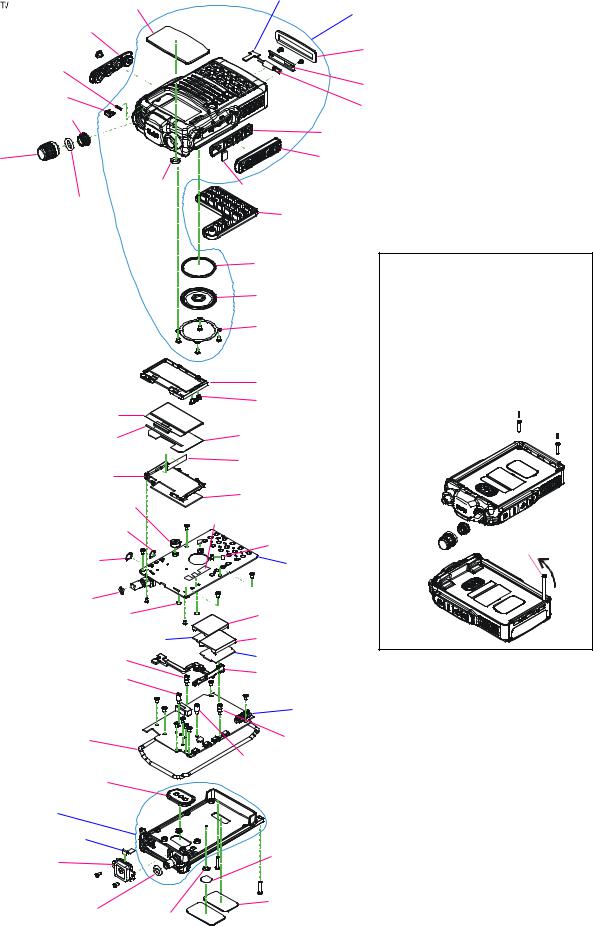
Exploded View & Miscellaneous Parts
|
RA124430A |
CONNECT Unit |
CP9697002 (USA) |
|
|
WINDOW ASSY (YAESU) |
|
CP9697003 (EXP) |
|
|
RA1229000 |
|
FRONT CASE ASSY |
|
|
|
|
||
|
CAP (SIDE) |
|
|
|
|
|
|
RA1231200 |
|
RA1229100 |
|
MASKSHEET(MOTOR) |
||
|
||||
RUBBER PACKING (LED) |
|
RA1229500 |
||
|
|
|
||
RA1228800 |
|
|
BRACKET (MOTOR) |
|
LIGHT GUIDE (LED) |
|
M2190034 |
||
RA060450B |
|
|||
|
VIBRATION MOTOR |
|||
SPECIAL NUT (M) |
|
|||
|
|
|||
|
|
|
RA1016900 |
|
RA1228600 |
|
|
SUPPORT (PTT) |
|
|
RA101320B |
|||
ENCODER KNOB |
|
|||
|
|
RUBBER (PTT) |
||
|
RA0434100 |
RA107300A |
|
|
|
SHEET(M-TEX1131) |
|
||
|
SPACER(PTT) |
|
||
|
|
|
||
|
RA1037500 |
|
|
|
|
O RING (6.5X2) |
RA1230000 |
||
|
|
|||
|
|
KEY PAD |
|
|
|
|
RA1229400 |
|
|
|
GASKET (SP) |
|
|
|
M4090189 |
|
|
|
SPEAKER(0.5W/16-ohm) |
|
|
|
RA101370B |
|
|
SP HOLDER |
||
|
|
|
|
|
|
RA1229300 |
|
|
|
RUBBER PACKING (LCD) |
|
Q7000614A |
|
RA1228900 (X2pcs) |
|
|
LIGHT GUIDE (WIN) |
||
LCD MODULE |
|
||
|
|
||
RA1273400 |
|
RA1271800 |
|
|
DIFFUSER SHEET (LCD) |
||
LCD SHEET(B) |
|
||
|
|
||
|
|
RA1271700 |
|
RA1228700 |
|
SHADING SHEET(LCD) |
|
|
|
||
LCD HOLDER |
|
RA1013800 |
|
|
|
||
RA1229200 |
|
SHEET (LCD) |
|
MIC HOLDER RUBBER |
RA1267500 |
||
|
|
||
RA1266400 |
|
DOUBLE FACE (RUBBER) |
|
MASK SHEET (DATA) |
|
RA1257100 (X2pcs) |
|
|
|
||
RA1257000 |
|
SPACER(SP) |
|
|
|||
MASK SHEET (EXT) |
|
CNTL Unit |
|
|
|
||
|
|
|
|
RA0603600 |
|
|
|
O RING (1X4.2) |
|
||
|
RA1007400 |
||
RA1272300 (X2pcs) |
|
||
|
SHIELD CASE VCO |
||
SHEET(CNT) |
|||
RA1007400 |
|||
|
|
||
SUB VCO Unit |
SHIELD CASE VCO |
||
Removing the Rear Case Assy
1.Please order the screw M2.6X30 (P/N; U00230001).
2.Remove the ENCODER KNOB (A) and SPECIAL SCREW (B).
3.Remove the two screws (C).
4.Turn the M2.6x30 screw several times to affix the screw to the bottom right corner.
5.Press the top of the screw toward to a panel top to remove the rear case Assy from the front panel.
(C)
 (C)
(C)
(B)
(A) 
screw M2.6X30
RA1229700 |
|
|
MAIN VCO Unit |
STUD A |
|
|
RA1274400 |
RA1229800 |
|
|
|
|
|
SUPPORT(CONT) |
|
STUD B |
|
|
|
|
|
||
|
|
|
|
|
RF Unit |
||
|
|
|
|
|
|
|
|
RA1012700 |
|
|
RA1229700 |
GASKET |
|
|
STUD A |
|
|
|
RA1229800
RA1012800 STUD B
PACKING PAD (POW)
CP9698001 CHASSIS ASSY
(w/ PACKING PAD, O RING,
SMA CONNECTOR)
CABLE Unit |
|
|
|
Q7000642 |
|
RA1267700 |
|
GPS MODULE |
|
||
SHEET (LABEL) |
|||
|
|
|
|
|
|
||
RA1037400 |
|
RA1231300 |
|
O RING (4.8X1.9) |
RA0337300 |
MASK SHEET (SW) |
|
|
|
SHEET
Non-designated parts are available only as part of a designated assembly.
|
|
|
|
|
|
|
|
|
|
RUBBER ANTENNA YHA-72 |
Q3000236 |
|||
AC-DC ADAPTOR NC-86B (USA) |
Q9500149 |
|||
AC-DC ADAPTOR NC-86C (EXP) |
Q9500150 |
|||
|
|
|
|
|
|
|
|
|
|
|
|
|
|
|
|
U07230102 |
PAN HEAD SCREW M2X3NI #1 |
1 |
|
|
U9900241 |
PAN HEAD TAPTITE-B 2X10SUS #3 |
2 |
|
|
U9900181 |
TAPTITE SCREW 2X3.5(CAP) |
|
1 |
|
U9900242 |
TAPPING SCREW 2X2.5NI |
|
6 |
|
U9900239 |
PAN HEAD TAPTITE-B 2X3NI #3 |
9 |
|
|
U9900243 |
TAPPING SCREW M2X3NI |
|
2 |
|
U9900240 |
PAN HEAD TAPTITE-B 1.4X3NI #3 |
2 |
|
|
U07240202 |
PAN HEAD SCREW M2X4NI#2 |
2 |
|
4 |
VX-8GR Technical Supplement |

Block Diagram
VX-8GR Technical Supplement |
5 |
Block Diagram
Note
6 |
VX-8GR Technical Supplement |
Introduction and Precautions
The 


 has been carefully aligned at the factory for the specified performance across the specified amateur bands. Realignment should therefore not be necessary except in the event of a component failure. All component replacement and service should be performed only by an authorized VERTEX STANDARD representative, or the warranty policy may be voided.
The following procedures cover the sometimes critical and tedious adjustments that are not normally required once the transceiver has left the factory. However, if damage occurs and some parts are replaced, realignment may be required. If a sudden problem occurs during normal operation, it is likely due to component failure; realignment should not be done until after the faulty component has been replaced.
We recommend that servicing be performed only by authorized VERTEX STANDARD service technicians, who are experienced with the circuitry and fully equipped for repair and alignment. Therefore, if a fault is suspected, contact the dealer from whom the transceiver was purchased for instructions regarding repair. Authorized VERTEX STANDARD service technicians realign all circuits and make complete performance checks to ensure compliance with factory specifications after replacing any faulty components.
Those who do undertake any of the following alignments are cautioned to proceed at their own risk. Problems caused by unauthorized attempts at realignment are not covered by the warranty policy. Also, VERTEX STANDARD must reserve the right to change circuits and alignment procedures in the interest of improved performance, without notifying owners.
Under no circumstances should any alignment be attempted unless the normal function and operation of the transceiver are clearly understood, the cause of the malfunction has been clearly pinpointed and any faulty components replaced, and the need for realignment determined to be absolutely necessary.
Alignment
Required Test Equipment
RF Signal Generator with calibrated output level at 500 MHz
Deviation Meter (linear detector)
In-line Wattmeter with 5% accuracy at 500 MHz
50-ohm, 10-W RF Dummy Load
8-ohm AF Dummy Load
RegulatedDCPowerSupplyadjustablefrom8 to16VDC,3A
Frequency Counter: 0.2-ppm accuracy at 500 MHz
AF Signal Generator
AC Voltmeter
DC Voltmeter: high impedance
UHF Sampling Coupler
SINAD Meter
Alignment Preparation & Precautions
A 10-W RF dummy load and in-line wattmeter must be connected to the main antenna jack in all procedures that call for transmission, alignment is not possible with an antenna. After completing one step, read the next step to see if the same test equipment is required. If not, remove the test equipment (except dummy load and wattmeter, if connected) before proceeding.
Correct alignment requires that the ambient temperature be the same as that of the transceiver and test equipment, and that this temperature be held constant between 68~86°F (20~30°C). When the transceiver is brought into the shop from hot or cold air, it should be allowed some time to come to room temperature before alignment. Whenever possible, alignments should be made with oscillator shields and circuit boards firmly affixed in place. Also, the test equipment must be thoroughly warmed up before beginning.
Note: Signal levels in dB referred to in the alignment procedure are based on 0 dBµ=0.5 µV (closed circuit).
VX-8GR Technical Supplement |
7 |

Alignment
Internal System Alignment Routine
This uses a programmed routine in the transceiver which simplifies many previously complex discrete component settings and adjustments with digitally-con- trolled settings via front panel buttons and LCD indications.
1.To begin, set the transceiver to the VFO mode on the "A-Band" in the "Mono" band mode.
2.Program a password for the Alignment (AH041M) according to the following procedure:
1)Press and hold the [MENU] key for one second to enter the Set mode.
2)Rotate the DIAL knob to select Set Mode Item 16: CW ID.
3)Press the [MENU] key briefly to enable adjustment of this Set Mode Item.
4)Rotate the DIAL knob to select "ON".
5)Press the [MODE] key, then press and hold in the [HM/RV] key for two seconds to clear any previous entry.
6)Program the password "AH041M" using the DIAL knob (select the character), and [BAND]/[MODE] key (move the cursor).
7)When you have completed the password, press the
[MENU] key briefly, then press the PTT switch to exit to normal operation.
Remember to delete the password "AH041M"from the Set Mode Item 16: CW ID when the alignment adjustments are finished by pressing and holding in the [HM/ RV] key for two seconds (as in step 5 above).
3.Press the [PWR] switch for two seconds to turn the transceiver "off".
4.Press and hold in the [HM/RV] key while powering the transceiver "on" again. The transceiver will enter the adjustment mode, and the display will show the first alignment setting. Thereafter, the frequencies used during alignment will automatically be set without action by the technician.


 DIAL
DIAL 


 [V/M]
[V/M] 


[V/M] 


 [HM/RV]


As each transceiver is individually optimized at the factory, the precise settings for the transceiver on your bench may be slightly different.
PLL Reference Frequency Adjustment (PLL REF)
Connect the test equipment as shown in Figure 1: TX Alignment Setup.
Rotate the DIAL knob to select the Alignment Menu "PLL REF".
Press the [V/M] button (the " " icon will appear on the display).
Press the PTT switch to transmit and rotate the DIAL knob so that the frequency counter setting is 440.000 MHz (±100 Hz).
Release the PTT switch, then press the [V/M] button (the " " icon will disappear from the display).
50-ohm RF
Dummy Load
Sampling
Coupler
In-Line
Wattmeter
Deviation
Meter
Frequency
Counter
Figure 1: TX Alignment Setup
RF Signal
Generator
8-ohm
AF Load
SINAD
Meter
Figure 2: RX Alignment Setup
8 |
VX-8GR Technical Supplement |
A-Band 430 MHz Band Adjustment
Receiver Sensitivity Adjustment (TUNE DC)
Connect the test equipment as shown in Figure 2: RX Alignment Setup.
Rotate the DIAL knob to select the Alignment Menu "TUNE DC".
Set the RF Signal Generator output to 435.100 MHz, at a level of -10 dBµ, ±3.5 kHz deviation with a 1 kHz audio tone.
Press the [V/M] button (the " " icon will appear on the display).
Rotate the DIAL knob for maximum deflection on the SINAD meter.
Press the [V/M] button (the " " icon will disappear on the display).
Squelch Hysteresis Confirmation (HIS SQL)
Rotate the DIAL knob to select the Alignment Menu "HIS SQL".
Confirm that the alignment value is "0".
Squelch Threshold Adjustment (THLD SQL)
Connect the test equipment as shown in Figure 2: RX Alignment Setup.
Rotate the DIAL knob to select the Alignment Menu "THLD SQL".
Set the RF Signal Generator output to 435.100 MHz, at a level of -12 dBµ, ±3.5 kHz deviation with a 1 kHz audio tone.
Press the [V/M] button (the " " icon will appear on the display).
Press the [F/W] key two times to store the Squelch Threshold level
Press the [V/M] button (the " " icon will disappear on the display).
Tight Squelch Adjustment (TIGH SQL)
Connect the test equipment as shown in Figure 2: RX Alignment Setup.
Rotate the DIAL knob to select the Alignment Menu "TIGH SQL".
Set the RF Signal Generator output to 435.100 MHz, at a level of -4 dBµ, ±3.5 kHz deviation with a 1 kHz audio tone.
Press the [V/M] button (the " " icon will appear on the display).
Press the [F/W] key two times to to store the Squelch Tight level.
Press the [V/M] button (the " " icon will disappear on the display).
Alignment
FM S-Meter S-1 Adjustment (S1 LEVEL)
Connect the test equipment as shown in Figure 2: RX Alignment Setup.
Rotate the DIAL knob to select the Alignment Menu "S1 LEVEL" with "NFM" icon.
Set the RF Signal Generator output to 435.100 MHz, at a level of -7 dBµ, ±3.5 kHz deviation with a 1 kHz audio tone.
Press the [V/M] button (the " " icon will appear on the display).
Press the [F/W] key two times to store the FM SMeter S-1 level.
Press the [V/M] button (the " " icon will disappear on the display).
FM S-Meter Full-Scale Adjustment (S9 LEVEL)
Connect the test equipment as shown in Figure 2: RX Alignment Setup.
Rotate the DIAL knob to select the Alignment Menu "S9 LEVEL" with "NFM" icon.
Set the RF Signal Generator output to 435.100 MHz, at a level of +20 dBµ, ±3.5 kHz deviation with a 1 kHz audio tone.
Press the [V/M] button (the " " icon will appear on the display).
Press the [F/W] key two times to store the FM SMeter Full Scale level.
Press the [V/M] button (the " " icon will disappear on the display).
VX-8GR Technical Supplement |
9 |
Alignment
TX Power (HI) Adjustment (HI POWER)
Connect the test equipment as shown in Figure 1: TX Alignment Setup.
Rotate the DIAL knob to select the Alignment Menu "HI POWER".
Press the [V/M] button (the " " icon will appear on the display).
Press the PTT switch to transmit and rotate the DIAL knob so that the Power Meter reading is 4.9 W (±0.1 W).
Release the PTT switch, and then press the [V/M] button (the " " icon will disappear on the display).
TX Power (L3) Adjustment (L3 POWER)
Connect the test equipment as shown in Figure 1: TX Alignment Setup.
Rotate the DIAL knob to select the Alignment Menu "L3 POWER".
Press the [V/M] button (the " " icon will appear on the display).
Press the PTT switch to transmit and rotate the DIAL knob so that the Power Meter setting is 2.5 W (±0.1 W).
Release the PTT switch, and then press the [V/M] button (the " " icon will disappear on the display).
TX Power (L2) Adjustment (L2 POWER)
Connect the test equipment as shown in Figure 1: TX Alignment Setup.
Rotate the DIAL knob to select the Alignment Menu "L2 POWER".
Press the [V/M] button (the " " icon will appear on the display).
Press the PTT switch to transmit and rotate the DIAL knob so that the Power Meter setting is 1.0 W (±0.1 W).
Release the PTT switch, and then press the [V/M] button (the " " icon will disappear on the display).
TX Power (L1) Adjustment (L1 POWER)
Connect the test equipment as shown in Figure 1: TX Alignment Setup.
Rotate the DIAL knob to select the Alignment Menu "L1 POWER".
Press the [V/M] button (the " " icon will appear on the display).
Press the PTT switch to transmit and rotate the DIAL knob so that the Power Meter setting is 50 mW (+30 mW/ -0 W).
Release the PTT switch, and then press the [V/M] button (the " " icon will disappear on the display).
TX Deviation Adjustment (MAX DEV)
Connect the test equipment as shown in Figure 1: TX Alignment Setup.
Rotate the DIAL knob to select the Alignment Menu "MAX DEV".
Set the AF Signal Generator output to 50 mVrms with a 1 kHz audio tone.
Press the [V/M] button (the " " icon will appear on the display).
Press the PTT switch to transmit and rotate the DIAL knob so that the Deviation Meter setting is 4.2 kHz ± 0.05 kHz (USA version) or 4.5 kHz ± 0.05 kHz (EXP version).
Release the PTT switch, and then press the [V/M] button (the " " icon will disappear on the display).
CTCSS TX Deviation Adjustment (100.0Hz)
Connect the test equipment as shown in Figure 1: TX Alignment Setup.
Rotate the DIAL knob to select the Alignment Menu "100.0Hz".
Press the [V/M] button (the " " icon will appear on the display).
Press the PTT switch to transmit without the microphone input and rotate the DIAL knob so that the Deviation Meter setting is 0.65 kHz (±0.05 kHz).
Release the PTT switch, and then press the [V/M] button (the " " icon will disappear on the display).
10 |
VX-8GR Technical Supplement |
Alignment
DCS TX Deviation Adjustment (DCS 023)
Connect the test equipment as shown in Figure 1: TX Alignment Setup.
Rotate the DIAL knob to select the Alignment Menu "DCS 023".
Press the [V/M] button (the " " icon will appear on the display).
Press the PTT switch to transmit without the microphone input and rotate the DIAL knob so that the Deviation Meter setting is 0.65 kHz (±0.05 kHz).
Release the PTT switch, and then press the [V/M] button (the " " icon will disappear on the display).
VX-8GR Technical Supplement |
11 |
Alignment
A-Band 144 MHz Band Adjustment
Press the [BAND] key to select the 144 MHz Amateur band.
Receiver Sensitivity Adjustment (TUNE DC)
Connect the test equipment as shown in Figure 2: RX Alignment Setup.
Rotate the DIAL knob to select the Alignment Menu "TUNE DC".
Set the RF Signal Generator output to 145.100 MHz, at a level of -10 dBµ, ±3.5 kHz deviation with a 1 kHz audio tone.
Press the [V/M] button (the " " icon will appear on the display).
Rotate the DIAL knob for maximum deflection on the SINAD meter.
Press the [V/M] button (the " " icon will disappear on the display).
Squelch Hysteresis Confirmation (HIS SQL)
Rotate the DIAL knob to select the Alignment Menu "HIS SQL".
Confirm that the alignment value is "0".
Squelch Threshold Adjustment (THLD SQL)
Connect the test equipment as shown in Figure 2: RX Alignment Setup.
Rotate the DIAL knob to select the Alignment Menu "THLD SQL".
Set the RF Signal Generator output to 145.100 MHz, at a level of -12 dBµ, ±3.5 kHz deviation with a 1 kHz audio tone.
Press the [V/M] button (the " " icon will appear on the display).
Press the [F/W] key two times to store the Squelch Threshold level.
Press the [V/M] button (the " " icon will disappear on the display).
Tight Squelch Adjustment (TIGH SQL)
Connect the test equipment as shown in Figure 2: RX Alignment Setup.
Rotate the DIAL knob to select the Alignment Menu "TIGH SQL".
Set the RF Signal Generator output to 145.100 MHz, at a level of +4 dBµ, ±3.5 kHz deviation with a 1 kHz audio tone.
Press the [V/M] button (the " " icon will appear on the display).
Press the [F/W] key two times to store the Squelch Tight level.
Press the [V/M] button (the " " icon will disappear on the display).
FM S-Meter S-1 Adjustment (S1 LEVEL)
Connect the test equipment as shown in Figure 2: RX Alignment Setup.
Rotate the DIAL knob to select the Alignment Menu "S1 LEVEL" with "NFM" icon.
Set the RF Signal Generator output to 145.100 MHz, at a level of -7 dBµ, ±3.5 kHz deviation with a 1 kHz audio tone.
Press the [V/M] button (the " " icon will appear on the display).
Press the [F/W] key two times to store the FM S-Meter S-1 level.
Press the [V/M] button (the " " icon will disappear on the display).
FM S-Meter Full-Scale Adjustment (S9 LEVEL)
Connect the test equipment as shown in Figure 2: RX Alignment Setup.
Rotate the DIAL knob to select the Alignment Menu "S9 LEVEL" with "NFM" icon.
Set the RF Signal Generator output to 145.100 MHz, at a level of +20 dBµ, ±3.5 kHz deviation with a 1 kHz audio tone.
Press the [V/M] button (the " " icon will appear on the display).
Press the [F/W] key two times to store the FM S-Meter Full Scale level.
Press the [V/M] button (the " " icon will disappear on the display).
12 |
VX-8GR Technical Supplement |
Wide FM S-Meter S-1 Adjustment (S1 LEVEL)
Connect the test equipment as shown in Figure 2: RX Alignment Setup.
Rotate the DIAL knob to select the Alignment Menu "S1 LEVEL" with "WFM" icon.
Set the RF Signal Generator output to 145.100 MHz, at a level of 0 dBµ, ±20 kHz deviation with a 1 kHz audio tone.
Press the [V/M] button (the " " icon will appear on the display).
Press the [F/W] key two times to store the Wide FM S- Meter S-1 level.
Press the [V/M] button (the " " icon will disappear on the display).
Wide FM S-Meter Full-Scale Adjustment (S9 LEVEL)
Connect the test equipment as shown in Figure 2: RX Alignment Setup.
Rotate the DIAL knob to select the Alignment Menu "S9 LEVEL" with "WFM" icon.
Set the RF Signal Generator output to 145.100 MHz, at a level of +20 dBµ, ±20 kHz deviation with a 1 kHz audio tone.
Press the [V/M] button (the " " icon will appear on the display).
Press the [F/W] key two times to store the Wide FM S- Meter Full Scale level.
Press the [V/M] button (the " " icon will disappear on the display).
TX Power (HI) Adjustment (HI POWER)
Connect the test equipment as shown in Figure 1: TX Alignment Setup.
Rotate the DIAL knob to select the Alignment Menu "HI POWER".
Press the [V/M] button (the " " icon will appear on the display).
Press the PTT switch to transmit and rotate the DIAL knob so that the Power Meter setting is 5.0 W (±0.1 W).
Release the PTT switch, then press the [V/M] button (the " " icon will disappear on the display).
Alignment
TX Power (L3) Adjustment (L3 POWER)
Connect the test equipment as shown in Figure 1: TX Alignment Setup.
Rotate the DIAL knob to select the Alignment Menu "L3 POWER".
Press the [V/M] button (the " " icon will appear on the display).
Press the PTT switch to transmit and rotate the DIAL knob so that the Power Meter setting is 2.5 W (±0.1 W).
Release the PTT switch, then press the [V/M] button (the " " icon will disappear on the display).
TX Power (L2) Adjustment (L2 POWER)
Connect the test equipment as shown in Figure 1: TX Alignment Setup.
Rotate the DIAL knob to select the Alignment Menu "L2 POWER".
Press the [V/M] button (the " " icon will appear on the display).
Press the PTT switch to transmit and rotate the DIAL knob so that the Power Meter setting is 1.0 W (±0.1 W).
Release the PTT switch, then press the [V/M] button (the " " icon will disappear on the display).
TX Power (L1) Adjustment (L1 POWER)
Connect the test equipment as shown in Figure 1: TX Alignment Setup.
Rotate the DIAL knob to select the Alignment Menu "L1 POWER".
Press the [V/M] button (the " " icon will appear on the display).
Press the PTT switch to transmit and rotate the DIAL knob so that the Power Meter setting is 50 mW (+30 mW/ -20 mW) (VX-8E Type: 0.2W±0.05W).
Release the PTT switch, then press the [V/M] button (the " " icon will disappear on the display).
VX-8GR Technical Supplement |
13 |
Alignment
TX Deviation Adjustment (MAX DEV)
Connect the test equipment as shown in Figure 1: TX Alignment Setup.
Rotate the DIAL knob to select the Alignment Menu "MAX DEV".
Set the AF Signal Generator output to 50 mVrms with a 1 kHz audio tone.
Press the [V/M] button (the " " icon will appear on the display).
Press the PTT switch to transmit and rotate the DIAL knob so that the Deviation Meter setting is 4.2 kHz ± 0.2 kHz (USA version) or 4.5 kHz ± 0.2 kHz (EXP/EU versions).
Release the PTT switch, and then press the [V/M] button (the " " icon will disappear on the display).
CTCSS TX Deviation Adjustment (100.0Hz)
Connect the test equipment as shown in Figure 1: TX Alignment Setup.
Rotate the DIAL knob to select the Alignment Menu "100.0Hz".
Press the [V/M] button (the " " icon will appear on the display).
Press the PTT switch to transmit without the microphone input and rotate the DIAL knob so that the Deviation Meter setting is 0.65 kHz (±0.05 kHz).
Release the PTT switch, and then press the [V/M] button (the " " icon will disappear on the display).
DCS TX Deviation Adjustment (DCS 023)
Connect the test equipment as shown in Figure 1: TX Alignment Setup.
Rotate the DIAL knob to select the Alignment Menu "DCS 023".
Press the [V/M] button (the " " icon will appear on the display).
Press the PTT switch to transmit without the microphone input and rotate the DIAL knob so that the Deviation Meter setting is 0.65 kHz (±0.05 kHz).
Release the PTT switch, then press the [V/M] button (the " " icon will disappear on the display).
B-Band 430 MHz Band Adjustment
Press and hold in the [B] key for two seconds to change the operating band to the "B-Band".
Note: When the transceiver recalls Alignment Menu "PLL REF",the[B]keyoperationisignored.Inthiscase,rotate the DIAL knob to select an Alignment Menu other than "PLLREF".
Receiver Sensitivity Adjustment (TUNE DC)
Connect the test equipment as shown in Figure 2: RX Alignment Setup.
Rotate the DIAL knob to select the Alignment Menu "TUNE DC".
Set the RF Signal Generator output to 435.100 MHz, at a level of -10 dBµ, ±3.5 kHz deviation with a 1 kHz audio tone.
Press the [V/M] button (the " " icon will appear on the display).
Rotate the DIAL knob for maximum deflection on the SINAD meter.
Press the [V/M] button (the " " icon will disappear on the display).
Squelch Hysteresis Confirmation (HIS SQL)
Rotate the DIAL knob to select the Alignment Menu "HIS SQL".
Confirm that the alignment value is "0".
Squelch Threshold Adjustment (THLD SQL)
Connect the test equipment as shown in Figure 2: RX Alignment Setup.
Rotate the DIAL knob to select the Alignment Menu "THLD SQL".
Set the RF Signal Generator output to 435.100 MHz, at a level of -11 dBµ, ±3.5 kHz deviation with a 1 kHz audio tone.
Press the [V/M] button (the " " icon will appear on the display).
Press the [F/W] key two times to store the Squelch Threshold level.
Press the [V/M] button (the " " icon will disappear on the display).
14 |
VX-8GR Technical Supplement |
Tight Squelch Adjustment (TIGH SQL)
Connect the test equipment as shown in Figure 2: RX Alignment Setup.
Rotate the DIAL knob to select the Alignment Menu "TIGH SQL".
Set the RF Signal Generator output to 435.100 MHz, at a level of -3 dBµ, ±3.5 kHz deviation with a 1 kHz audio tone.
Press the [V/M] button (the " " icon will appear on the display).
Press the [F/W] key two times to store the Squelch Tight level.
Press the [V/M] button (the " " icon will disappear on the display).
FM S-Meter S-1 Adjustment (S1 LEVEL)
Connect the test equipment as shown in Figure 2: RX Alignment Setup.
Rotate the DIAL knob to select the Alignment Menu "S1 LEVEL" with "NFM" icon.
Set the RF Signal Generator output to 435.100 MHz, at a level of -7 dBµ, ±3.5 kHz deviation with a 1 kHz audio tone.
Press the [V/M] button (the " " icon will appear on the display).
Press the [F/W] key two times to store the FM S-Meter S-1 level.
Press the [V/M] button (the " " icon will disappear on the display).
Alignment
FM S-Meter Full-Scale Adjustment (S9 LEVEL)
Connect the test equipment as shown in Figure 2: RX Alignment Setup.
Rotate the DIAL knob to select the Alignment Menu "S9 LEVEL" with "NFM" icon.
Set the RF Signal Generator output to 435.100 MHz, at a level of +20 dBµ, ±3.5 kHz deviation with a 1 kHz audio tone.
Press the [V/M] button (the " " icon will appear on the display).
Press the [F/W] key two times to store the FM S-Meter Full Scale level.
Press the [V/M] button (the " " icon will disappear on the display).
NOTICE: Do not touch the following Alignment Menus:
"PLL REF"
"HI POWER"
"L3 POWER"
"L2 POWER"
"L1 POWER"
"MAX DEV"
"HI POWER" "100.0Hz" "DCS 023"
VX-8GR Technical Supplement |
15 |
Alignment
B-Band 144 MHz Band Adjustment
Press the [BAND] key to select the 144 MHz Amateur band.
Receiver Sensitivity Adjustment (TUNE DC)
Connect the test equipment as shown in Figure 2: RX Alignment Setup.
Rotate the DIAL knob to select the Alignment Menu "TUNE DC".
Set the RF Signal Generator output to 145.100 MHz, at a level of -10 dBµ, ±3.5 kHz deviation with a 1 kHz audio tone.
Press the [V/M] button (the " " icon will appear on the display).
Rotate the DIAL knob for maximum deflection on the SINAD meter.
Press the [V/M] button (the " " icon will disappear on the display).
Squelch Hysteresis Confirmation (HIS SQL)
Rotate the DIAL knob to select the Alignment Menu "HIS SQL".
Confirm that the alignment value is "0".
Squelch Threshold Adjustment (THLD SQL)
Connect the test equipment as shown in Figure 2: RX Alignment Setup.
Rotate the DIAL knob to select the Alignment Menu "THLD SQL".
Set the RF Signal Generator output to 145.100 MHz, at a level of -11 dBµ, ±3.5 kHz deviation with a 1 kHz audio tone.
Press the [V/M] button (the " " icon will appear on the display).
Press the [F/W] key two times to store the Squelch Threshold level.
Press the [V/M] button (the " " icon will disappear on the display).
Tight Squelch Adjustment (TIGH SQL)
Connect the test equipment as shown in Figure 2: RX Alignment Setup.
Rotate the DIAL knob to select the Alignment Menu "TIGH SQL".
Set the RF Signal Generator output to 145.100 MHz, at a level of -3 dBµ, ±3.5 kHz deviation with a 1 kHz audio tone.
Press the [V/M] button (the " " icon will appear on the display).
Press the [F/W] key two times to store the Squelch Tight level.
Press the [V/M] button (the " " icon will disappear on the display).
FM S-Meter S-1 Adjustment (S1 LEVEL)
Connect the test equipment as shown in Figure 2: RX Alignment Setup.
Rotate the DIAL knob to select the Alignment Menu "S1 LEVEL" with "NFM" icon.
Set the RF Signal Generator output to 145.100 MHz, at a level of -7 dBµ, ±3.5 kHz deviation with a 1 kHz audio tone.
Press the [V/M] button (the " " icon will appear on the display).
Press the [F/W] key two times to store the FM S-Meter S-1 level.
Press the [V/M] button (the " " icon will disappear on the display).
16 |
VX-8GR Technical Supplement |
Alignment
FM S-Meter Full-Scale Adjustment (S9 LEVEL)
Connect the test equipment as shown in Figure 2: RX Alignment Setup.
Rotate the DIAL knob to select the Alignment Menu "


 " with "NFM" icon.
Set the RF Signal Generator output to 145.100 MHz, at a level of +20 dBµ, ±3.5 kHz deviation with a 1 kHz audio tone.
Press the [V/M] button (the " " icon will appear on the display).
Press the [F/W] key two times to store the FM S-Meter Full Scale level.
Press the [V/M] button (the " " icon will disappear on the displayy).
NOTICE: Do not touch the following Alignment Menus:
"PLL REF"
"HI POWER"
"L3 POWER"
"L2 POWER"
"L1 POWER"
"MAX DEV"
"HI POWER" "100.0Hz" "DCS 023"
This completes the internal alignment routine for all bands. To save all settings and exit, press the [HM/RV] button.
VX-8GR Technical Supplement |
17 |
Alignment
Note
18 |
VX-8GR Technical Supplement |
 Loading...