

Page 1
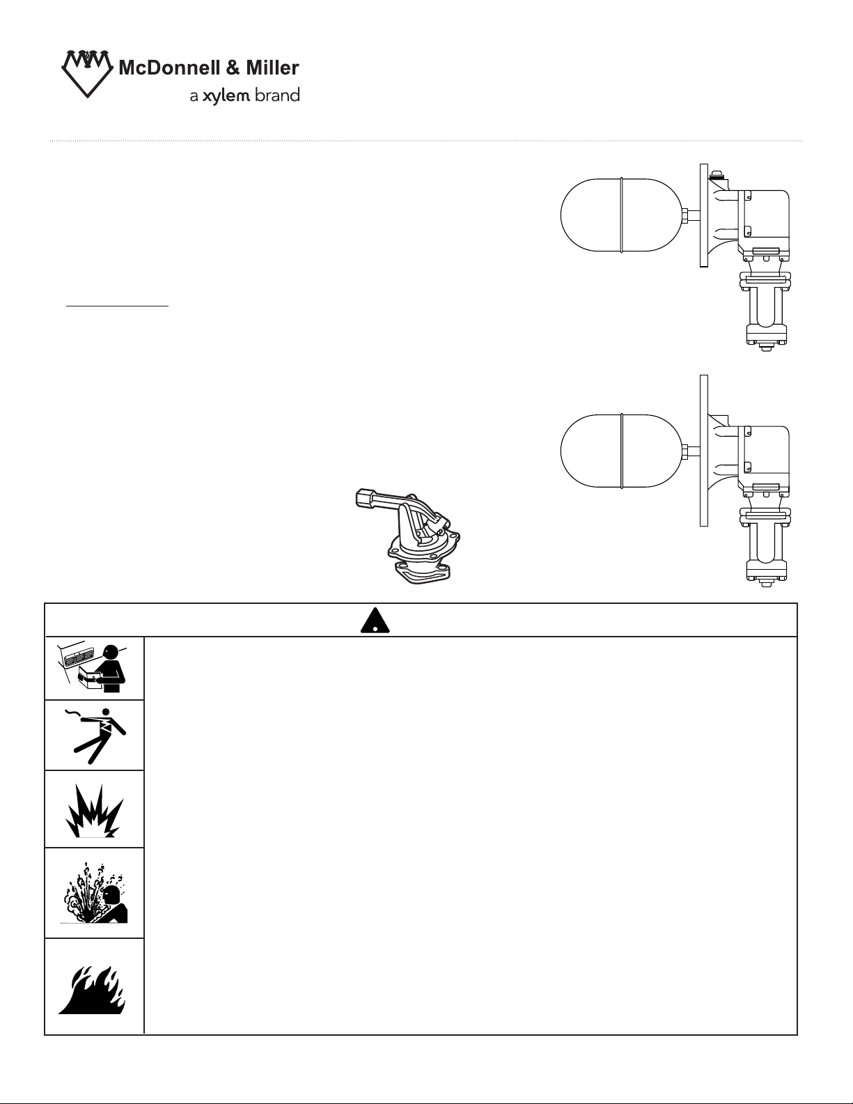
Model 21 and 221
Mechanical Water Feeders
And Replacement Valve Assembly SA21-6
Applications:
For receiver tanks in industrial or
commercial applications.
Maximum water supply pressure: 150 PSIG (10.55 kg/cm2)
2
Maximum vessel pressure: 35 PSIG (2.46 kg/cm
Maximum fluid temperature: 120°F (49°C)
)
INSTRUCTION MANUAL
MM-317C
Model 21
SA21-6
WARNING
!
TION
CAU
ING
WARN
• Before using this product read and understand instructions.
• Save these instructions for future reference.
• All work must be performed by qualified personnel trained in the proper application, installation, and maintenance of plumbing, steam, and electrical equipment and/or systems in
accordance with all applicable codes and ordinances.
• Drain water level down below feeder and let cool to 80° (27°C) before servicing.
• If tank or receiver is pressurized relieve pressure to 0 psi (0 Bar) before servicing.
• To prevent water damage check to make sure there is adequate floor drainage capacity.
Check all components in the system to insure they will not leak in the event of an
overfeed condition.
California Proposition 65 warning! This product contains chemicals known to the
•
state of California to cause cancer and birth defects or other reproductive harm.
Previous controls should never be installed on a new system. Always install new
•
controls on a new boiler or system.
Failure to follow this warning could cause property damage, personal inj ury or death.
CAUTION:
•
A more frequent replacement interval may be necessary based on the condition of
the unit at time of inspection. McDonnell Miller s warranty is one (1) year from date
of installation or two (2) years from the date of manufacture.
!
&
'
Model 221
Page 2
2
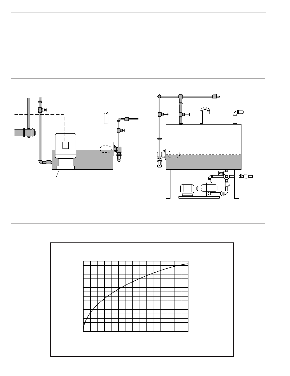
OPERATION
Capacities
WATER SUPPLY PRESSURE IN LBS. PER SQ. IN.
CAPACITY CURVE
lbs./hr.
psi
(kg/hr.)
13 012 011010 09080706050403010
16,000
15,000
14,000
13,000
12,000
11,000
10,000
9,000
8,000
7,000
6,000
5,000
4,000
3,000
2,000
1,000
0
(7258)
(6804)
(6350)
(5897)
(5443)
(4990)
(4536)
(4082)
(3629)
(3175)
(2722)
(2268)
(1814)
(1361)
(907)
(454)
(0)
(0.7) (1.4) (2.1)(2.8) (3.5) (4.2) (4.9) (5.6)(6.3) (7.0) (7.7) (8.4) (9.1)(9.8) (10.5)
200
(0)
14 0 15 0
32
30
28
26
24
22
20
18
16
14
12
10
8
6
4
2
0
(121.12)
(113.55)
(105.98)
(98.41)
(90.84)
(83.27)
(75.70)
(68.13)
(60.56)
(52.99)
(45.42)
(37.85)
(30.28)
(22.71)
(15.14)
(7.57)
(0)
(kg/cm
2
)
gpm
(lpm)
464
435
406
377
348
319
290
261
232
203
174
145
116
87
58
29
0
(4549)
(4264)
(3980)
(3696)
(3411)
(3127)
(2843)
(2559)
(2274)
(1990)
(1706)
(1421)
(1137)
(853)
(569)
(284)
(0)
Boiler Hp
(kilowatts)
The Series 21 make-up water feeder provides
dependable, float-operated automatic water filling
service to tanks used as condensate receivers in
boiler systems. The valve components are of brass,
an elastomer sealing disc and stainless steel materials, and a 4-3/4” diameter copper float providing
closure against supply pressure up to 150 PSI. An
integral strainer and housing with removable drainage
plug precede the valve for regular servicing. The control is a direct-feeding unit (feeds through the flange
connection) available in two flange sizes.
TYPICAL INSTALLATIONS
Boiler
Feed
Tank
MODEL 221
City Water Supply
Check Valve
Bypass
Condensate Receiver Tank
MODEL 21
Feed Pump
Pump
Discharge
Feed Pump
Page 3

3
INSTALLATION
TOOLS NEEDED:
One (1) adjustable wrench, socket wrenches, two (2)
pipe wrenches, pipe dope, assorted fittings and lengths
of 3/4” pipe.
STEP 1 - Preparation
This Water Feeder mounts directly on the
tank or vessel. The tank or vessel is to be
manufactured with a mating flange (A)
and opening large enough for the float.
The flange can be either welded flush on
the side or head and have pre-tapped
mounting holes (preferred), or a necked
or nozzle flange with plain mounting
holes. Either must have a 1-3/8” maximum
distance from the outer flange face to the
interior wall surface to allow the float to
fully drop to get maximum valve capacity.
City Water Supply
Check Valve
Bypass
Condensate Receiver Tank
Pump
Discharge
Feed Pump
MODEL 21
The feeder is usually mounted one-third
(1/3) of the way up from the bottom of the
tank. This provides two-thirds (2/3) of the
tank for return condensate.
Follow the diagram for piping the feeder
to the tank and water supply. Remember
to leave room for the servicing the water
feeder. At all right angle turns in the
equalizing piping, crosses should be used
to facilitate inspection and cleaning.
STEP 2 - Install the Piping
Flange Dimension Details
e
Tank w/
Flange
1-3/8”
MAX.
1-3/8”
MAX.
Bulk
Head
Flang
NO. 21
NO. 221
Page 4

INSTALLATION (cont.)
21 Series - Replacement Valve Assembly (SA21-6)
a. Remove Feeder from Tank. Turn off the water
supply and drain the tank below the level of the
feeder flange. If fluid is heated, allow system to
cool to 80°F (27°C) before disassembly.
Disconnect the piping above the strainer assembly. Remove the six (6) mounting bolts and lift off
the feeder from the tank.
b. Remove Valve Assembly. Remove float and
rod from the float arm of the valve linkage.
Unscrew the two (2) bolts from the strainer body
at the bottom of the valve assembly. Unscrew
the four (4) bolts from the valve body at the bottom of the valve housing bracket. Pull the valve
assembly from the housing in an arcing movement to clear the float arm from the interior.
c. Reassemble with new Valve Assembly.
Position the new valve assembly with new
gasket, float arm first, into the housing. Hand
secure the four (4) bolts and tighten to 16 ft/lbs.
Replace the strainer body and new gasket using
the two (2) bolts. Tighten to 16 ft/lbs. Reattach
the float and rod onto the float arm and hand
tighten.
d. Replace Feeder on Tank. Replace the assem-
bly and new gasket onto the tank flange. Tighten
the six (6) bolts to 16 ft/lbs. Reconnect the
piping and restore water supply. Check for proper closing level and leakage before leaving the
jobsite.
Note: Use new gaskets; make sure all gasket
surfaces are clean.
Housing Gasket
SA21-6
Replacement
Valve
Housing
Strainer
Assembly
MAINTENANCE:
• Blow down tank weekly during heating season.
Blow down may have to be more frequent
depending on local water conditions and the
amount of make-up water.
Xylem Inc.
8200 N. Austin Avenue
Morton Grove, Illinois 60053
Phone: (847) 966-3700
Fax: (847) 965-8379
www.xyleminc.com/brands/mcdonnellmiller
McDonnell & Miller is a trademark of Xylem Inc. or one of its subsidiaries.
© 2013 Xylem Inc. MM-317C July 2013 Part No. 246731
• Clean strainer at least twice during heating
season. Cleaning may have to be more frequent
depending on local water conditions and the
amount of make-up water.
• Replace control every 15 years.
 Loading...