

Page 1
E
Page 2
2
Determine which situation applies:
a. For models 51-2, 51-S-2 or 53-2 on steam boilers:
Always set the control to shut off the burner while
there is water visible in the gauge glass. This applies
when the gauge glass is directly mounted in the boiler
or on a water column.
b. For models 51, 51-S or 53 on steam boilers:
Set the line on the casting 3
1
/8" below the boiler
manufacturer’s normal water level.
c. For all models on steam process boilers when no
condensate is returned to the boiler: Set the line
on the casting 11/8" below the boiler manufacturer’s
normal water level.
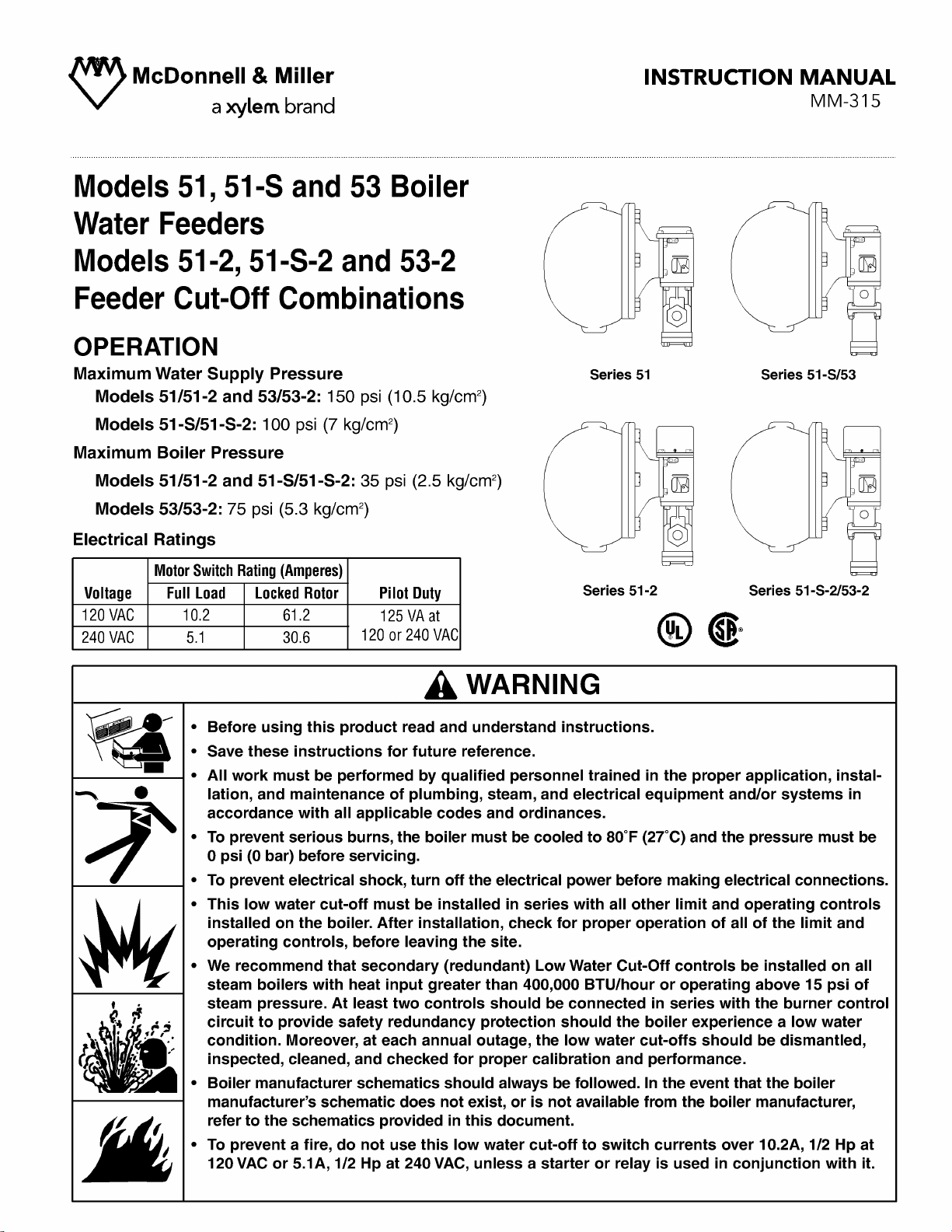
Models 51 / 51-2, Models 51-S / 51-S-2 and Models 53 / 53-2 –
For Steam Boilers with 1” (25mm) Equalizing Lines
INSTALLATION –
TOOLS NEEDED:
One (1) flathead screwdriver and two (2) pipe wrenches.
STEP 1 - Determine the Location of the Feeder and/or Low Water Cut-Off
Operating Levels of 51/51-2,
51-S/51-S-2 or 53/53-2
Drip tight valve off – 11/8"
Casting line – 0”
Burner on –1/8" (±1/4")
Burner off –7/8" (±1/4")
Series 51 and 53 Operating Level
California Proposition 65 warning! This product contains chemicals known to the
•
state of California to cause cancer and birth defects or other reproductive harm.
Previous controls should never be installed on a new system. Always install new
•
controls on a new boiler or system.
Failure to fo
CAUTION:
•
A more frequent replacement interval may be necessary based on the condition of
the unit at time of inspection. McDonnell & Miller's warranty is one (1) year from date
of installation or two (2) years from the date of manufacture.
llow this warning could cause property damage, personal injury or death.
Casting
Line
Valve Off -11/8"
Casting Line - 0"
Burner On - 1/8" (± 1/4")
Burner Off -
7
/8" (± 1/4")
Page 3

a. Using the criteria in Step 1,
determine the location of the
51/51-2, 51-S/51-S-2 or 53/53-2.
This applies when the gauge
glass is directly mounted in the
boiler or on a water column.
b. Use Figure 1 or Figure 2 as a
general guide.
c. Connect steam equalizing lines
to any available opening other
than steam flow line.
(Take off line).
d. Test the Model 51/51-2, 51-S/51-S-2 and 53/53-2 Before Turning it Over to the Owner
Open the blow-down valve while burner is operating. As the water level drops the feeder will begin to
add water. As the water continues to drop the burner will shut off (on the 51-2, 51-S-2 and 53-2 only).
STEP 2 - Installation of the Models 51/51-2, 51-S/51-S-2 and 53/53-2
3
Lower
Gauge
Glass
Connect to Return
Header on Boiler
Side of all Valves
1" Crosses
Gauge Glass
Level
Mark
1" Steam Equalizing Line
(Short as Possible)
1" Minimum Blow-down
Valve for Feeder
Float Chamber
1" Water
Equalizing Line
(Short as Possible)
Cold City Supply
Normal Water Line
Swing Check Valve
By-Pass
Feeder Casting Mark
(See Installation Location)
1" Crosses
Level
Mark
Water
Column
1" Steam Equalizing Line (Short as Possible)
1" Minimum Blow-down Valve
for Feeder Float Chamber
Normal Water Line
Feeder Casting Mark
(See Installation Location)
Connect to Return
Header on Boiler
Side of all Valves
Swing Check Valve
Cold City Supply
By-Pass
1" Water Equalizing Line (Short as Possible)
1" Minimum Blow-down Valve
Figure 1
Gauge Glass Mounted in the Boiler
Figure 2
Gauge Glass Mounted on a Water Column
Page 4

4
Strainer
Basket
Assembly
Swing Check Valve
By-pass
Hand By-Pass Valve
Connect to return
header on boiler
side of all valves
City Water
Supply
Supply To
Feeder
CAUTION
Before turning
on city water
pressure be
sure to open
this valve
a. Follow the drawing to the right for piping the
valve to boiler and city water supply. When
piping the valve remember to leave room for
servicing the valve.
Models 51 / 51-2, Models 51-S / 51-S-2 and Models 53 / 53-2
For Steam or Hot Water Boilers
INSTRUCTIONS FOR PIPING THE WATER FEEDER VALVE
TOOLS NEEDED:
Two (2) pipe wrenches.
STEP 1 - Piping the Valve on Models 51/51-2
Swing Check Valve
By-pass
Hand By-Pass
Valve
Connect to return
header on boiler
side of all valves
CAUTION
Before turning
on city water
pressure be
sure to open
this valve
City Water
Supply
Supply
Valve
Strainer
Basket
Assembly
a. Follow the drawing to the right for piping the
valve to the boiler and city water supply.
When piping the valve remember to leave
room for servicing the valve.
STEP 2 -
Piping the Valve on Models 51-S/51-S-2, 53/53-2
Page 5

5
Models 51-2, 51-S-2 and 53-2
ELECTRICAL WIRING
TOOLS NEEDED:
One (1) flathead screwdriver.
Conduit opening facing
toward float chamber
Conduit opening facing
away from float chamber
Manual reset button
on No. 2m Switch
a. The No. 2 switch can be positioned with the
conduit opening facing toward or away from
the float chamber. These are the only positions
in which the switch will function properly.
See drawing at right.
b. On initial fill-up, push the 2M manual reset
button after the proper water level is reached
to energize the burner. If a low water condition
occurs and the water level has been restored,
push the reset button to energize the burner.
c. Follow the wiring diagrams below to wire the
No. 2 Switch. Terminals C and NC are the low
water cut-off switch. Terminals C and NO are
alarm switch. If the electrical load exceeds the
rating of the switch, use an auxiliary relay or
motor starter.
USED AS A MAIN LINE SWITCH
AND/OR LOW WATER ALARM
USED AS A PILOT SWITCH TO COIL
OF RELAY OR MOTOR STARTER
N.
O.
N.C.
C.
N. O.
N.C.
C.
Neutral
120 V.A.C.
Supply Hot
Low
Water
Alarm
Burner
Circuit
Line
Load
SCHEMATIC OF SWITCH OPERATION
Water Level Normal
Burner On
Alarm Off
Low
Water
Alarm
Terminals
Low Water
Cut-Off
Terminals
C.
N.O.
N.C.
Water Level Low
Burner Off
Alarm On
C.
N.O.
N.C.
N.
O.
N.C.
C.
• To prevent electrical shock, turn off the electrical power before making electrical connections.
• This low water cut-off must be installed in series with all other limit and operating controls installed on the
boiler. After installation, check for proper operation of all of the limit and operating controls, before leaving
the site.
Failure to follow this warning could cause electrical shock, an explosion and/or a fire, which could result in
property damage, personal injury or death.
!
WARNING
Page 6

6
STEP 3 - Testing and Inspection
Blow-Down
Valve
Feeder
Valve
Closing
Level
The feeder should be blown down after initial installation, before leaving site. It should also be blown down
as recommended in the Maintenance section of these
instructions.
• Burner should be on and water level above 'closing
level' of feeder.
• Slowly open the water feeder blow down valve, which
will lower the water level in the float chamber. As
water flows out the blow down pipe, you should begin
to hear the feeder valve open.
• If the feeder has a #2 switch, the burner should stop.
• Close the water feeder blow down valve. The water
level should return to a safe operating level and the
burner should turn on.
To prevent serious personal injury from steam pipe
blow down, connect a drain pipe to the control
opening to avoid exposure to steam discharge.
Failure to follow this caution could cause personal
injury.
!
CAUTION
Swing check
TO BOILER
By-pass
valve
A
B
Make sure that the water level in the boiler is above the
closing level of the feeder.
Close valve 'A' and slowly open union 'B' to determine if
valve is leaking.
• If water is leaking from the union, the valve needs to
be serviced.
• If no water leaks from the union, the feeder operation
is not the cause of the flooding.
Broken Union Test
Blow Down of Feeder
E
D
B
H
x 4
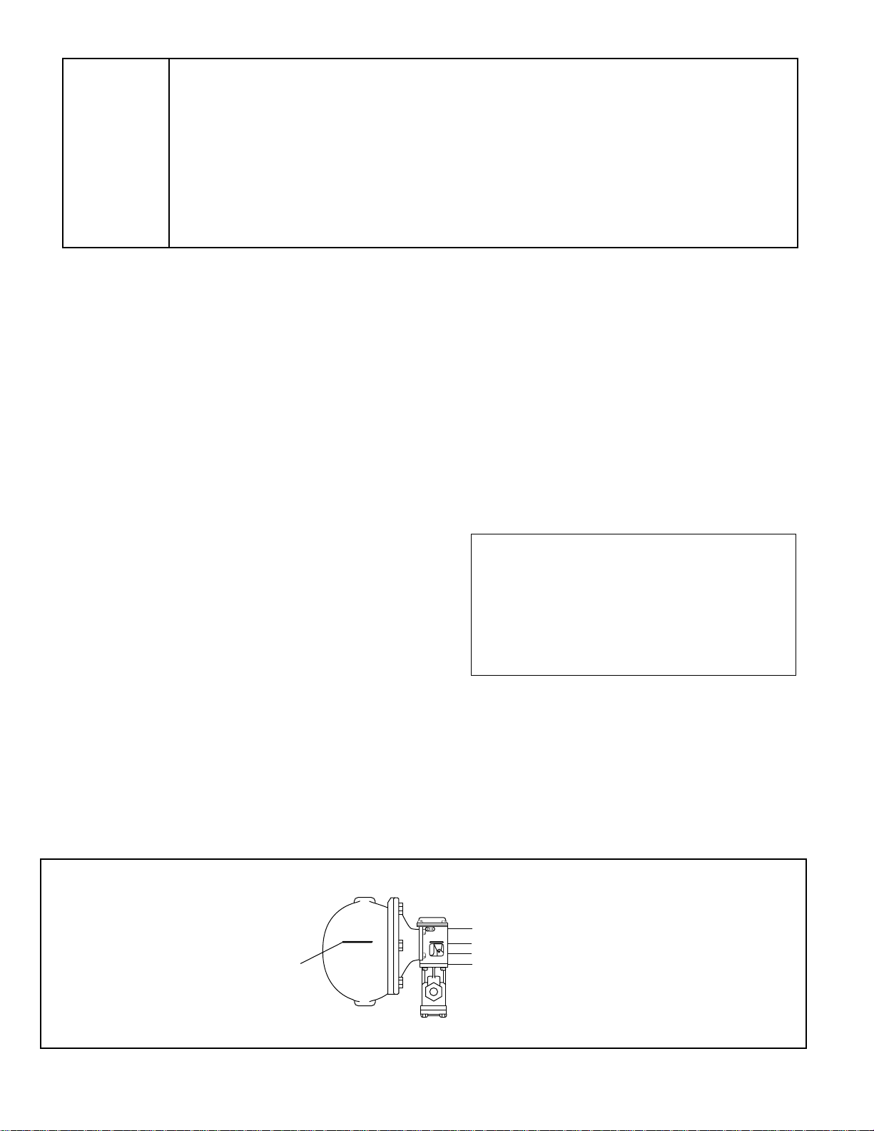
A. Using a 1/2" socket wrench, unscrew the four (4) hex-head
bolts (B) that secure the strainer basket (H) to the valve
assembly (E).
B. Using a 13/16" socket wrench, unscrew the cartridge (D)
and remove.
C. Clean any debris (scale, rust, etc.) from strainer and cartridge.
Poppet inside cartridge must move freely. Replace if debris
cannot be removed or poppet does not move freely.
D. Lubricate cartridge o-rings using silicone type lubricant and
re-install.
E. Re-install strainer basket.
Series 51
Removal of cartridge and strainer for inspection and cleaning
Page 7

7
The following is intended as a guide to determine why the feeder may not be operating as intended. Please note that
there can be system and installation issues that can affect the operation of the feeder. This includes but is not limited to
the following:
• Piping not installed properly • Priming and foaming of boiler water
• Faulty check valve in return header • Delay in condensate returning to boiler
• Tankless coil leaking
TROUBLESHOOTING
B
A. Using a 1/2" wrench, unscrew the four (4) hex-head
bolts (B) that secure the strainer.
B. Clean any debris (scale, rust, etc.) from strainer.
Replace if debris cannot be removed.
C. Re-install strainer.
Series 51-S/53
Removal of strainer for inspection and cleaning
Boiler is getting too much water.
a) Cause: The valve is not shutting off.
Test: Perform broken union test.
Solution:
• Series 51 Feeders Only: Remove and inspect
cartridge. Clean or replace as necessary.
• Series 51-S and 53 Feeders Only: There may be
debris lodged in the valve preventing it from closing
completely. Remove and clean valve assembly.
Replace if necessary.
b) Cause: By-pass valve is leaking.
Test: Perform broken union test.
Solution: Repair or replace valve.
c) Cause: Float chamber clogged with sediment.
Test: Open blow-down valve. If there is little or no
water flow, the chamber may be clogged with sediment.
Solution: Remove head assembly from float chamber
and clean sediment from chamber, float and bellows
mechanism. Replace head mechanism if necessary.
d) Cause: Float has filled with water.
Solution: Replace float.
e) Cause: Equalizing piping is plugged.
Solution: Clean or replace piping.
f) Cause: City water supply is above 150 psi (51, 53
Feeders) or 100 psi (51-S Feeder).
Solution: Install pressure reducing valve to reduce
water pressure.
Boiler is not getting enough water.
a) Cause: There is something preventing the valve from
fully opening.
Test: Perform broken union test.
Solution:
• Series 51 Feeders Only: Remove and inspect
cartridge. Clean or replace as necessary.
• Series 51-S and 53 Feeders Only: There may be
debris lodged in the valve preventing it from closing
completely. Remove and clean valve assembly.
Replace if necessary.
b) Cause: Strainer clogged with sediment.
Test: Perform broken union test.
Solution: Remove and inspect strainer. Clean or
replace as necessary.
c) Cause: Float chamber clogged with sediment.
Test: Open blow-down valve. If there is little or no
water flow, the chamber may be clogged with sediment.
Solution: Remove head assembly from float chamber
and clean sediment from chamber, float and bellows
mechanism. Replace head mechanism if necessary.
d) Cause: Feed line between valve and boiler is partially
plugged.
Test: Perform broken union test. With union broken,
there should be water flowing through the piping from
the boiler.
Solution: Clean or replace piping.
e) Cause: Feed line between valve and city water supply
is plugged.
Solution: Clean or replace piping.
f) Cause: Water supply pressure less than boiler
pressure.
Solution: Reduce boiler pressure or convert to pumped
return.
Page 8

TROUBLESHOOTING (cont'd)
Unit is making noise.
(Series 51 Feeders Only)
a) Cause: Under certain system conditions, there may be
a vibration when the valve mechanism (cartridge poppet)
is slightly open.
Solution: Install a pressure reducing valve such as the
Bell & Gossett B-38 in the inlet water line before the
feeder valve.
Burner switch not working.
a) Cause: Cam worn or broken.
Solution: Replace cam assembly (CO-106/302900).
b) Cause: Linkages not transferring float movement to
switch.
Solution:
• Linkage pins may be worn or broken which would
require purchasing a new valve assembly:
-for 51/51-2: SA51-101-102/342500
-for 53/53-2: SA53-6/342800
-for 51-S/51-S-2: SA515-6/342100
• Float may be damaged, sediment may have
accumulated in chamber or equalizing piping may be
plugged. Perform testing to determine what the
problem may be and correct.
Water leaking from bellows
a) Cause: Continuous exposure to chemicals with pH
higher than 9.0 will cause the solder to deteriorate.
Solution: Remove source of chemicals or consider
replacing control with one that is suitable for the
application.
MAINTENANCE
SCHEDULE:
Daily
• Blow down when boiler is in operation if boiler operating
pressure is above 15 psi.
Weekly
• Blow down when boiler is in operation if boiler operating
pressure is below 15 psi.
Annually
• Disassemble and inspect/clean strainer screen.
Replace if screen is torn or not able to be cleaned.
• Remove and inspect/clean cartridge. (For Series 51
Feeders Only). Replace if poppet does not move freely
or debris cannot be removed.
• Remove head and inspect internal parts. Clean out all
mud, silt, sediment and debris from chamber, float
mechanism and other waterside components.
• Inspect equalizing piping. Clean or replace as
required.
• Check all wires for brittle or worn insulation.
• Check for leaks at gasket surfaces and solder joints.
NOTE
Use clean water to rinse components and surfaces. DO
NOT use sharp objects to scrape off any accumulations
of sediment or debris.
Replace entire unit including equalizing piping every
10 years.
More frequent cleaning or replacement may be
required if used in locations where water treatment is
required or in applications with high make-up water
requirements.
Xylem, Inc.
8200 N. Austin Avenue
Morton Grove, Illinois 60053
Phone: (847) 966-3700
Fax: (847) 965-8379
www.xyleminc.com/brands/mcdonnellmiller
McDonnell & Miller is a trademark of Xylem Inc. or one of its subsidiaries.
© 2013 Xylem Inc. MM-315E July 2013 Part No. 210424
 Loading...