

Page 1
INSTRUCTION MANUAL
IM188
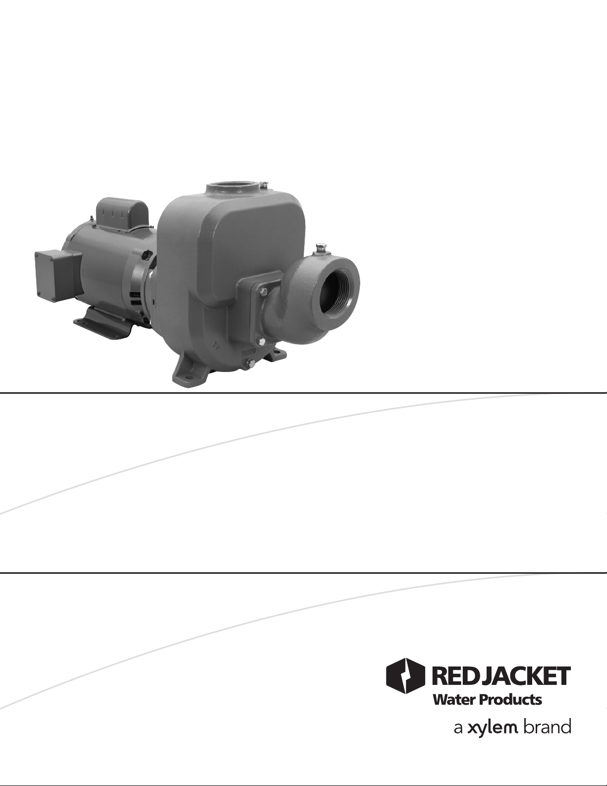
Model SPM/SPH
Self-Priming Pumps
INSTALLATION, OPERATION AND MAINTENANCE INSTRUCTIONS
Page 2

Owner’s Information
Owner’s Information
Please fill in data from your pump nameplate.
Warranty information is on page 8.
Model Number:
Serial Number:
Dealer:
Dealer Telephone:
Purchase Date:
Installation Date:
Table of Contents
Table of Contents
SUBJECT PAGE
Safety Instructions ..........................................................2
Description and Specifications ........................................2
Engineering Data ............................................................2
Piping
Suction .......................................................................2
Discharge ....................................................................3
Wiring and Grounding ...................................................3
Operation .......................................................................3
Rotation .........................................................................3
Maintenance...................................................................3
Disassembly ....................................................................4
Reassembly .....................................................................4
Repair Parts ....................................................................5
Troubleshooting .............................................................5
Limited Warranty ...........................................................8
Declaration of Conformity ...........................................23
2
Page 3
SAFETY INSTRUCTIONS
DANGER
WARNING
WARNING
Hazardous fluids
can cause fire,
burns or death.
TO AVOID SERIOUS OR FATAL PERSONAL INJURY OR
MAJOR PROPERTY DAMAGE, READ AND FOLLOW ALL
SAFETY INSTRUCTIONS IN MANUAL AND ON PUMP.
This is a SAFETY ALERT SYMBOL. When
you see this symbol on the pump or in the
manual, look for one of the following signal
words and be alert to the potential for personal injury or property damage.
Warns of hazards that WILL cause serious
personal injury, death or major property
damage.
Warns of hazards that CAN cause serious
personal injury, death or major property
damage.
CAUTION
NOTICE: INDICATES SPECIAL INSTRUCTIONS
WHICH ARE VERY IMPORTANT AND
MUST BE FOLLOWED.
THIS MANUAL IS INTENDED TO ASSIST IN THE
INSTALLATION AND OPERATION OF THIS UNIT
AND MUST BE KEPT WITH THE PUMP.
MAINTAIN ALL SAFETY DECALS.
NOTICE: INSPECT UNIT FOR DAMAGE AND
REPORT ALL DAMAGE TO THE CARRIER
OR DEALER IMMEDIATELY. DO NOT USE
PUMP IF DAMAGE IS SUSPECTED.
DESCRIPTION AND SPECIFICATIONS
DESCRIPTION AND SPECIFICATIONS
• The SPM/SPH Series embraces a line of end suction single
stage, self-priming centrifugal pumps for lawn
sprinkling, HVAC systems, and general water transfer.
• Casing is cast iron construction with tapped openings
provided for vacuum gauge and casing drain.
• Impeller is bronze, enclosed design, balanced for smooth
operation and keyed to motor shaft.
• ALL motors are NEMA standard, 3500 RPM, open drip
proof or TEFC enclosure.
Warns of hazards that CAN cause personal
injury or property damage.
UNIT NOT DESIGNED FOR USE
WITH HAZARDOUS LIQUIDS OR
FLAMMABLE GASES.
ENGINEERING DATA
ENGINEERING DATA
Prime Line SP Data
Flange Size
SPH130
SPH330 3/60
SPM130
SMP330 3/60
SPH150
SPH350 3/60
SPM150
SPM350 3/60
Suction Impeller HP
Model
SPF20A 5.94
SPF25A 5.06 3 2
SPF25A 6.19 5 2
SPF30A
5.82 5 2½
Discharge Phase/Hz
3 1½
1/60
1/60
1/60
1/60
Table 1
• Maximum Liquid Temperature: 160º F (71º C)
• Starts per hour: 20 – evenly distributed.
PIPING
PIPING
• Pump MUST be installed horizontally on a solid flat surface,
with discharge on top.
• Allow adequate space for servicing and ventilation. Protect
the unit from weather and water damage due to rain or
flooding or freezing temperatures.
• Piping should be no smaller than the suction and discharge
connections and kept as short as possible, avoiding unneces-
sary ttings to minimize friction losses. See Table 1.
• All piping MUST be independently supported and MUST
NOT place any piping loads on the pump.
NOTICE: DO NOT FORCE PIPING INTO PLACE AT
PUMP SUCTION AND DISCHARGE
CONNECTIONS.
• The use of Teon™ tape, or equivalent, is recommended for
ALL pipe joints.
• All pipe joints MUST be airtight.
PIPING – SUCTION
• Total suction lift, including elevation and pipe friction loss,
should not exceed 25 feet.
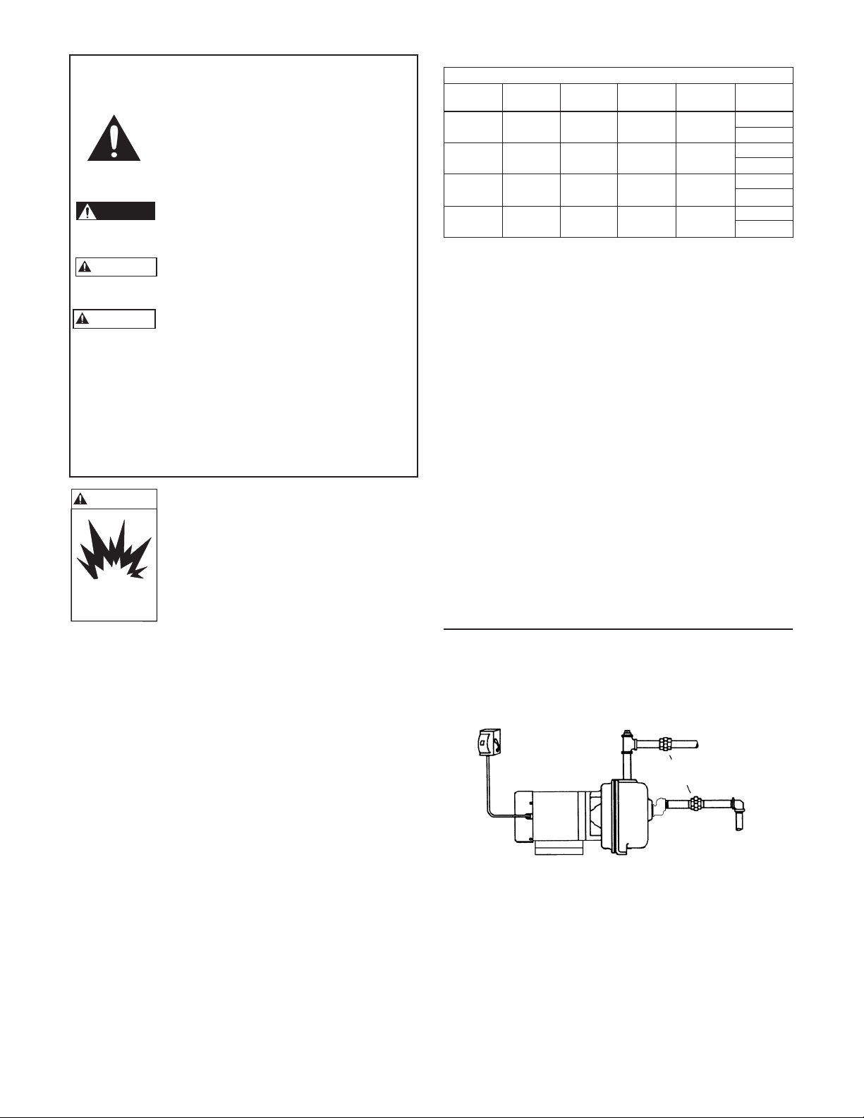
• Install an airtight union in the suction line close to the pump.
See Figure 1.
PRIMING
FUSED OR
CIRCUIT BREAKER
DISCONNECT MEANS
OPENING
DISCHARGE
UNION
SUCTION
Figure 1
3
Page 4
• Installation of a foot valve at the liquid source, or a check
WARNING
Hazardous voltage
can shock, burn or
cause death.
WARNING
Hazardous voltage
can shock, burn or
cause death.
Extreme heat can
cause personal injury
or property damage.
WARNING
Hazardous
Machinery
WARNING
Hazardous pressure
can cause personal
injury or property
damage.
CAUTION
valve after the pump discharge, is recommended.
NOTICE: FOR INSTALLATIONS WITH LONG SUCTION
PIPING, BOTH A FOOT VALVE AND A
CHECK VALVE ARE RECOMMENDED.
• To avoid air pockets, no part of the piping should be above
the pump suction connection and piping should slope up-
ward from liquid source.
• For installations with long suction piping, ll the suction pipe
with water before connecting to pump.
PIPING – DISCHARGE
• Install a tee at the discharge connection of the pump. The top
opening of the tee is required for initial priming. See Figure 1.
WIRING AND GROUNDING
WIRING AND GROUNDING
Install, ground and wire according
to local and National Electrical
Code requirements.
Install an all leg electrical power
disconnect switch near the pump.
Disconnect electrical power, before
installing or servicing pump.
Electrical supply MUST match pump’s nameplate
specifications. Incorrect voltage can cause fire, damage to the motor, and voids warranty.
Motors without built-in protection MUST be
provided with contactors and thermal overloads
for single phase motors, or starters with heaters for
three phase motors. See motor nameplate.
• Follow motor manufacturer’s wiring diagram on the motor
nameplate or terminal cover carefully.
• Use only copper wire to motor and ground. The ground wire
MUST be at least as large as the wire to the motor. Wires
should be color coded for ease of maintenance.
WARNING
Hazardous
voltage
FAILURE TO PERMANENTLY
GROUND THE PUMP, MOTOR AND
CONTROLS BEFORE CONNECTING
TO ELECTRICAL POWER CAN CAUSE
SHOCK, BURNS, OR DEATH.
• Fill pump through opening in top of tee with clean water.
See Figure 1.
• Install pipe plug in top using Teon™ tape or equivalent on
male threads.
NOTICE: IF PUMP IS DRAINED OR SHUT OFF DURING
PRIMING PERIOD, ENSURE CASING IS
REFILLED BEFORE RESTARTING PUMP.
• Start the pump motor and wait for system pressure to stabilize.
If system pressure is surging, or prolonged pressure drop is
experienced, the system may not be completely primed.
ROTATION
ROTATION
NOTICE: INCORRECT ROTATION MAY CAUSE
DAMAGE TO THE PUMP AND VOIDS THE
WARRANTY.
• Correct rotation is right hand, CLOCKWISE when viewed
from the motor end.
• Single phase motors with more than 4 wires (leads) may be
reversible designs. Insure that the motor is rotating in the correct direction. See motor nameplate for wiring instructions.
• Three phase unit rotation may be checked by removing motor end cap or plug and observing rotation of motor shaft. To
reverse rotation, reverse any two of the three motor leads.
MAINTENANCE
MAINTENANCE
FAILURE TO DISCONNECT AND
LOCKOUT ELECTRICAL POWER
BEFORE ATTEMPTING ANY MAINTENANCE CAN CAUSE SEVERE PERSONAL INJURY.
FAILURE TO RELIEVE SYSTEM PRESSURE AND DRAIN SYSTEM BEFORE
ATTEMPTING ANY MAINTENANCE
CAN CAUSE SERIOUS PERSONAL
INJURY OR PROPERTY DAMAGE.
OPERATION
OPERATION
4
SPLASHING OR IMMERSING OPEN
DRIP PROOF MOTORS IN WATER
CAN CAUSE FIRE, SHOCK, BURNS OR
DEATH.
OPERATION WITHOUT PRIME, OR
AGAINST A CLOSED DISCHARGE
VALVE, CAN GENERATE HOT WATER
OR STEAM CAUSING INJURY OR
PROPERTY DAMAGE OR EXPLOSION
RESULTING IN SERIOUS PERSONAL
INJURY, PROPERTY DAMAGE OR
DEATH.
• No lubrication is required on pump. For motor lubrication,
refer to and follow manufacturer’s instructions.
Seasonal Service
• To REMOVE pump from service, remove all drain plugs and
drain all piping.
• To RETURN pump to service, replace all drain plugs using
Teon™ tape or equivalent.
• Reconnect suction line if removed, examine union and repair
if necessary.
• Reprime and operate pump following all instructions and
warnings in the “OPERATION” section of manual.
Page 5

DISASSEMBLY
DISASSEMBLY
• Follow ALL warnings and instructions in the
“MAINTENANCE” section of this manual.
1. Remove motor hold down bolts.
2. Remove suction ange bolts (16).
3. Remove suction ange (17).
4. Remove check valve assembly (15).
5. Remove casing bolts (12).
6. Remove back pull-out assembly from casing (1).
7. Remove diffuser (4) and diffuser seal ring (3).
Discard ring.
8. Insert a screwdriver into one of the impeller waterways to
restrain motor shaft from rotation and remove impeller
bolt (6). Discard.
9. Remove impeller washer (7), impeller (8) and impeller
key (14). If the impeller is difcult to remove, insert two
pry bars between impeller and adapter, 180º apart and
CAREFULLY pry off impeller.
10. Remove motor adapter bolts (12) and adapter from motor
pulling with it the mechanical seal (9).
11. Push stationary seat of mechanical seal out of the motor
adapter and discard.
12. Inspect shaft sleeve (13). If damaged or badly scored,
remove by heating with a torch. Discard.
NOTICE: EXERCISE CARE IN HANDLING HOT SHAFT
SLEEVE.
REASSEMBLY
REASSEMBLY
• All parts should be cleaned before reassembly.
• Refer to parts list for description of replacement items.
Specify pump order number when ordering parts.
1. Inspect shaft, removing any debris or burrs.
2. When replacing shaft sleeve, apply new shaft sleeve’s bore
with LOCQUIC® Primer N, or equivalent. Let parts dry
and then apply LOCTITE® #262 on the same surfaces.
Slide new sleeve over shaft with a twisting motion, wipe off
excess. Let cure according to instructions.
NOTICE: MECHANICAL SEAL MUST BE REPLACED
WHENEVER SEAL HAS BEEN REMOVED.
FOLLOW SEAL MANUFACTURER’S
INSTRUCTIONS CAREFULLY.
3. If necessary, seat ring may be lubricated with water or
glycerin to aid in installation. DO NOT contaminate the
seal face. Fully and squarely install the stationary seat into
the adapter. With a clean cloth, CAREFULLY wipe the
seat face clean of debris. DO NOT damage the seal
seat face.
4. Reinstall the motor adapter on the motor, making sure that
the motor shaft does not dislocate or damage the stationary
seal seat.
5. Fully and squarely install the seal rotary assembly against
the stationary seat. Be sure rotating seal face does not drop
out of the holding collar and DO NOT damage seal face.
6. Install impeller key in shaft keyway. Mount impeller on
shaft and push until it bottoms.
7. Install new impeller washer.
8. Insert a screwdriver in a waterway passage of the impeller
holding it against rotation and install the new impeller bolt.
Torque to 20 lbs-ft (27 N•M).
9. Remove any burrs caused by screwdriver on the impeller
waterway passages.
10. Remove and replace the “o” ring (10) on the motor
adapter. Lubricate lightly with Parker “O” ring lube or
equivalent.
11. Locate the diffuser on the motor adapter with the stop
piece in the 12 o'clock position.
12. Locate the diffuser seal ring on the machined nose of the
diffuser and make sure it's pushed rmly into place.
13. Install motor and rotating assembly into casing, check the
position of the seall ring, tighten casing bolts alternately
and evenly. Torque to 37 lbs-ft (50 N•M).
14. Check impeller for binding by rotating the motor shaft.
If binding occurs, loosen bolts, readjust diffuser until
impeller hub turns freely. Tighten bolts again.
15. Place suction flange bolts through holes and locate check
valve assembly (replace if damaged) over bolts. Carefully
bolt suction flange on casing making sure check valve
assembly is positioned so that the rubber face is against the
angled face of the suction flange.
16. Replace motor foot bolts.
17. Check for free rotation after assembly is complete.
18. Replace all drain plugs, using teon tape on male threads.
19. Prime according to instructions in the “OPERATION”
section of the manual.
5
Page 6
COMPONENTS
WARNING
Hazardous voltage
can shock, burn or
cause death.
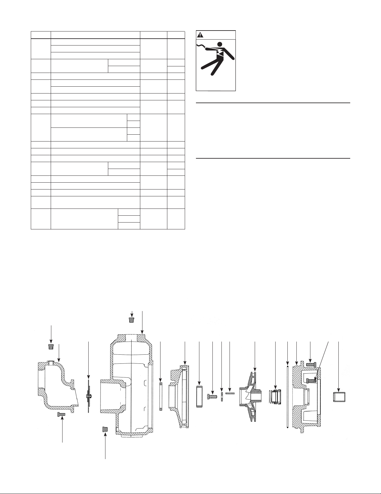
COMPONENTS TROUBLESHOOTING
Location Description Material Qty.
Case 1½" NPT
1 Case 2" NPT Cast Iron 1
Case 2½" NPT
2 Pipe Plug ¼" NPT
Case Steel 2
3 Diffuser Seal Ring BUNA 1
4 Diffuser – High Head
Diffuser – Medium Head
5 Casing Wear Ring Bronze* 1
6 Impeller Screw
7 Impeller Washer 1
8 3 HP
3 HP
9 Mechanical Seal ** 1
10 O-Ring BUNA-N 1
11 Motor Adapter – 140/180 FR Cast Iron 1
12 Hex Head Cap Screw Case Zinc Plated 8
.38 – 16 UNC .88 Lg Motor Steel 4
13 Shaft Sleeve
14 Key – Square End
15 Check Valve Assembly BUNA-SS 1
Steel
1" NPT
17 Suction Flange 2½" NPT Cast Iron 1
3" NPT
* Lead Free
** Consult Factory
Impeller – High Head
Impeller – Medium Head
16 Hex Head Cap Screw .31 – 18 UNC .75 Lg
Suction Flange Zinc Plated 1
Cast Iron
AISI 300 SS
5 HP
5 HP
AISI 300 SS 1
Zinc Plated
1
Sil-Brass* 1
1
4
TROUBLESHOOTING
FAILURE TO DISCONNECT
ELECTRICAL POWER BEFORE ATTEMPTING ANY MAINTENANCE
CAN CAUSE SHOCK, BURNS OR
DEATH.
SYMPTOM
Motor Not Running:
See Probable Causes 1 through 5.
Little or No Water Delivered:
See Probable Causes 3, 4, 6 through 12, 15, 16.
Excessive Noise and Vibration:
See Probable Causes 3, 6, 7, 10, 12, 13, 14.
PROBABLE CAUSES
1. Motor thermal protector tripped.
2. Open circuit breaker or blown fuse.
3. Impeller binding.
4. Motor improperly wired.
5. Defective motor.
6. Pump is not primed, air or gases in pumpage.
7. Discharge, suction plugged or valve closed.
8. Incorrect rotation.
9. Low voltage or phase loss.
10. Impeller worn or plugged.
11. System head too high.
12. NPSHA too low – excessive suction lift or loss.
13. Discharge head too low – excessive ow rates.
14. Pump, motor or piping loose.
15. End of suction piping not submerged.
16. Check valve damaged.
2 1
2
17
16
15 3 4 5 7 14 8 96 10 11 12 12 13
2
6
Page 7

NOTES
NOTES
7
Page 8

RED JACKET WATER PRODUCTS LIMITED WARRANTY
This warranty applies to all water systems pumps manufactured by Red Jacket Water Products.
Any part or parts found to be defective within the warranty period shall be replaced at no charge to the dealer during the warranty period. The war-
ranty period shall exist for a period of twelve (12) months from date of installation or eighteen (18) months from date of manufacture, whichever
period is shorter.
A dealer who believes that a warranty claim exists must contact the authorized Red Jacket Water Products distributor from whom the pump was
purchased and furnish complete details regarding the claim. The distributor is authorized to adjust any warranty claims utilizing the Red Jacket Water
Products Customer Service Department.
The warranty excludes:
(a) Labor, transportation and related costs incurred by the dealer;
(b) Reinstallation costs of repaired equipment;
(c) Reinstallation costs of replacement equipment;
(d) Consequential damages of any kind; and,
(e) Reimbursement for loss caused by interruption of service.
For purposes of this warranty, the following terms have these definitions:
(1) “Distributor” means any individual, partnership, corporation, association, or other legal relationship that stands between Red Jacket Water Products
and the dealer in purchases, consignments or contracts for sale of the subject pumps.
(2) “Dealer” means any individual, partnership, corporation, association, or other legal relationship which engages in the business of selling or leasing
pumps to customers.
(3) “Customer” means any entity who buys or leases the subject pumps from a dealer. The “customer” may mean an individual, partnership, corpora-
tion, limited liability company, association or other legal entity which may engage in any type of business.
THIS WARRANTY EXTENDS TO THE DEALER ONLY.
Xylem, Inc.
2881 East Bayard Street Ext., Suite A
Seneca Falls, NY 13148
Phone: (866) 325-4210
Fax: (888) 322-5877
www.xyleminc.com/brands/redjacketwaterproducts
Red Jacket Water Products is a trademark of Xylem Inc. or one of its subsidiaries.
© 2012 Xylem Inc. IM188 Revision Number 1 July 2012
Page 9

MANUAL DE INSTRUCCIÓN
IM188
Modelo SPM y SPH
Self-Priming Pumps
INSTRUCCIONES DE INSTALACIÓN, FUNCIONAMIENTO Y MANTENIMIENTO
Page 10

INFORMACIÓN DEL PROPIETARIO
INFORMACIÓN DEL PROPIETARIO
Por favor complete los datos consultando la placa del
fabricante de la bomba. La información de la garantía está
en la página 16.
Número del modelo:
Número de serie:
Agente:
Teléfono del agente:
Fecha de compra:
Fecha de instalación:
ÍNDICE
ÍNDICE
ASUNTO PÁGINA
Instrucciones de seguridad ............................................10
Descripción y especificaciones ......................................10
Datos técnicos ..............................................................10
Tubería
Succión .....................................................................10
Descarga ...................................................................11
Cableado y conexión a tierra ........................................11
Operación ....................................................................11
Rotación .......................................................................11
Mantenimiento .............................................................11
Desmontaje ..................................................................12
Reensamblaje ................................................................12
Piezas de reparación .....................................................13
Investigación de averías ................................................13
Garantía limitada ..........................................................16
Declaración de Conformidad .........................................23
10
Page 11

PELIGRO
ADVERTENCIA
PRECAUCIÓN
ADVERTENCIA
Los fluidos peligrosos
pueden originar fuego,
quemaduras o causar
la muerte.
INSTRUCCIONES DE SEGURIDAD
ES INTENCIÓN QUE ESTE MANUAL ASISTA EN
LA INSTALACIÓN DE ESTA UNIDAD Y DEBE
MANTENERSE CON LA BOMBA.
Este es un SÍMBOLO DE ALERTA DE
SEGURIDAD. Cuando vea este símbolo
en la bomba o en el manual, busque una
de las palabras de señal y esté alerta a las
lesiones corporales potenciales o daños a
la propiedad.
Advierte los peligros que CAUSARÁN
lesiones corporales serias, la muerte o
daños mayores a la propiedad.
Advierte los peligros que PUEDEN causar
lesiones corporales serias, la muerte o
daños mayores a la propiedad.
Advierte los peligros que PUEDEN causar
lesiones corporales o daños a la propiedad.
ES INTENCIÓN QUE ESTE MANUAL ASISTA
EN LA INSTALACIÓN Y OPERACIÓN DE ESTA
UNIDAD Y DEBE MANTENERSE CON LA BOMBA.
MANTENGA TODAS LAS CALCOMÍAS DE
SEGURIDAD.
AVISO: INSPECCIONE LA UNIDAD SI TIENE
DAÑOS Y REPORTE INMEDIATEMENTE
CUALQUIER DAÑO AL TRANSPORTISTA
O AL AGENTE. NO USE LA BOMBA SI SE
SOSPECHA QUE ESTÁ DAÑADA.
UNIDADES NO DISEÑADAS PARA
USO CON LÍQUIDOS PELIGROSOS O
GASES INFLAMMABLES.
AVISO: INDICA INSTRUCCIONES ESPECIALES QUE
SON MUY IMPORTANTES Y DEBEN
SEGUIRSE.
DESCRIPCIÓN Y ESPECIFICACIONES.
DESCRIPCIÓN Y ESPECIFICACIONES.
• La serie SPM/SPH abarca una línea de bombas centrífu-
gas de aspiración axial, de una etapa, autocebadas para la
aspersión de patios, sistemas de calefacción, ventilación y
aire acondicionado, y transferencia de agua en general.
• La carcasa es de construcción de hierro fundido con
aberturas roscadas proporcionadas para el manómetro de
vacío y el drenaje de la carcasa.
• Impulsor de bronce, de diseño cerrado, equilibrado para
un funcionamiento suave y enchavetado al eje del motor.
• Todos los motores son de Norma NEMA, de 3500 rpm,
con cubierta abierta a prueba de goteo o con cubierta
totalmente cerrada enfriada con ventilador.
DATOS TÉCNICOS
DATOS TÉCNICOS
Datos sobre Prime Line SP
succión impulsor
SPH130
SPH330 3/60
SPM130
SMP330 3/60
SPH150
SPH350 3/60
SPM150
SPM350 3/60
Pestaña de Tamaño del
Modelo
SPF20A 5.94
SPF25A 5.06 3 2
SPF25A 6.19 5 2
SPF30A
HP
5.82 5 2½
3 1½
Descarga Fase/Hz
1/60
1/60
1/60
1/60
Tabla 1
• Máxima temperatura del líquido: 160º F (71º C)
• Arranques por hora: 20, distribuidos uniformemente.
TUBERÍA
TUBERÍA
• La bomba DEBE estar instalada horizontalmente sobre
una superficie plana y sólida, con la descarga por arriba.
• Deje suciente espacio superior para poder dar servicio y
ventilación. Proteja la unidad de la intemperie y del daño
de agua debido a la lluvia, inundaciones o temperaturas de
congelación.
• La tubería no debe ser más pequeña que las conexiones
de la succión y descarga y se deben mantener tan cortas
como sea posible, evitando accesorios innecesarios para
minimizar las pérdidas de fricción. Vea la tabla 1.
• Toda la tubería DEBE estar soportada
independientemente y NO DEBE agregar ninguna carga
de la tubería a la bomba.
AVISO: NO FUERCE LA TUBERÍA AL HACER LAS
CONEXIONES DE SUCCIÓN Y DESCARGA
CON LA BOMBA.
• El uso de la cinta de Teon™, o equivalente se recomienda
en TODAS las juntas de tubería.
• Todas las juntas de tubería DEBEN estar selladas para
evitar entrada de aire.
TUBERÍA – SUCCIÓN
• La altura de aspiración total, incluyendo la elevación y
las pérdidas de fricción de la tubería, no deben exceder
25 pies.
• Instale una unión estanca en la línea de succión, cerca de
la bomba. Vea la Figura 1.
INTERUPTOR
CON FUSIBLE O
CONMUTADOR
AUTOMÁTICO
ABERTURA DE
CEBADO
DESCARGA
UNIÓN
SUCCIÓN
Figura 1
• Se recomienda la instalación de una válvula de pie en
la fuente del líquido, o una válvula de retención después
de la descarga de la bomba.
11
Page 12

AVISO: PARA INSTALACIONES CON TUBERÍAS DE
ADVERTENCIA
La tensión peligrosa puede
causar electrochoque,
quemaduras o la muerte.
Tensión
p
eligrosa
ADVERTENCIA
ADVERTENCIA
La tensión peligrosa puede
causar electrochoque,
quemaduras o la muerte.
ADVERTENCIA
El calor extremo
puede causar lesiones
personales o daños
materiales.
Maquinaria peligrosa
ADVERTENCIA
PRECAUCIÓN
Niveles de presión
peligrosos pueden causar
lesiones personales o
daños materiales.
SUCCIÓN LARGAS, SE RECOMIENDA UNA
VÁLVULA DE PIE Y UNA VÁLVULA DE
RETENCIÓN.
• Para evitar las bolsas de aire, ninguna parte de la tubería
• Para instalaciones con tuberías de succión largas, llene la
TUBERÍA – DESCARGA
• Instale una T en la conexión de descarga de la bomba. La
CABLEADO Y CONEXIÓN A TIERRA
CABLEADO Y CONEXIÓN A TIERRA
• Siga cuidadosamente el diagrama de alambrado del fabri-
• Use sólo cables de cobre al motor y a tierra. El alambre a
OPERACIÓN
OPERACIÓN
12
debe estar arriba de la conexión de succión de la bomba
y la tubería debe inclinarse hacia arriba, partiendo de la
fuente del líquido.
tubería de succión con agua antes de conectar la bomba.
abertura superior de la T se requiere para el cebado inicial.
Vea la Figura 1.
Instale la conexión a tierra y el
cableado de acuerdo con los
requerimientos del código
Nacional de Electricidad.
Instale un interruptor de
alimentación en todos los alam-
bres exteriores con corriente,
cerca de la bomba.
Desconecte la alimentación
eléctrica antes de instalar o dar
servicio a la bomba.
La alimentación eléctrica DEBE estar de acuerdo
con las especificaciones de la placa del fabricante.
La tensión incorrecta puede causar incendio o
dañar el motor y anular la garantía.
Los motores sin protección incorporada DEBEN
estar provistos de contactores y sobrecargas
térmicas para los motores monofásicos, o con
arrancadores con calentadores para los trifásicos.
Vea la placa del fabricante del motor.
cante del motor en la placa del fabricante del motor o en
la tapa terminal.
tierra DEBE ser por lo menos tan grande como el alambre
al motor. Los alambres deben ser de color codificado para
facilitar el mantenimiento.
LA OMISIÓN DE CONECTAR A
TIERRA PERMENENTEMENTE LA
BOMBA, EL MOTOR Y LOS CONTROLES, ANTES DE CONECTAR A LA
ALIMENTACIÓN ELÉCTRICA, PUEDE
CAUSAR ELECTROCHOQUES,
QUEMADURAS O LA MUERTE.
SALPICAR O SUMERGIR LOS
MOTORES DE CUBIERTA ABIERTA A
PRUEBA DE GOTEO EN UN FLUIDO
PUEDE CAUSAR INCENDIOS,
ELECTROCHOQUES, QUEMADURAS
O LA MUERTE.
TRABAJAR SIN CEBADOR, O
CONTRA UNA VÁLVULA DE
DESCARGA CERRADA, PUEDE
GENERAR AGUA CALIENTE O
VAPOR QUE PODRÍA CAUSAR
LESIONES O DAÑOS A LA
PROPIEDAD O UNA EXPLOSIÓN
QUE PODRÍA CAUSAR LESIONES
CORPORALES GRAVES, DAÑOS A
LA PROPIEDAD O LA MUERTE
• Llene la bomba a través de la abertura superior de la T,
con agua limpia. Vea la Figura 1.
• Instale el tapón de la tubería en la parte superior de la
T usando cinta de Teon™ o equivalente en las roscas
macho.
AVISO: SI LA BOMBA ESTÁ VACIA O CERRADA
AL MOMENTO DEL CEBADO, ASEGÚRESE
DE QUE LA CARCASA SE VUELVA A LLENAR
ANTES DE VOLVER A ARRANCAR
LA BOMBA.
• Arranque el motor de la bomba y espere que la presión
del sistema se estabilice. Si la presión del sistema está con
pulsación, o se experimenta una prolongada caída de presión, es probable que el sistema no esté totalmente cebado.
ROTACIÓN
ROTACIÓN
AVISO: LA ROTACIÓN INCORRECTA PUEDE
CAUSAR DAÑO A LA BOMBA Y ANULAR
LA GARANTÍA.
• La rotación correcta es la derecha, en sentido HORARIO
cuando se mira desde el extremo del motor.
• La rotación de la unidad trifásica se puede vericar
quitando la tapa extrema del motor o tapón y observando
la rotación del eje del motor. Para invertir la rotación, in-
vierta dos cualesquiera de los tres conductores del motor.
MANTENIMIENTO
MANTENIMIENTO
LA OMISIÓN DE DESCONECTAR
Y TRABAR LA ALIMENTACIÓN
ELÉCTRICA ANTES DE INTENTAR
CUALQUIER MANTENIMIENTO
PUEDE CAUSAR SEVERAS LESIONES
CORPORALES.
LA OMISIÓN DE ALIVIAR LA
PRESIÓN DEL SISTEMA Y DRENAR
EL SISTEMA ANTES DE INTENTAR
CUALQUIER MANTENIMIENTO
PUEDE CAUSAR LESIONES
CORPORALES GRAVES O DAÑOS
A LA PROPIEDAD.
• La bomba no requiere lubricación alguna. Para la lubricación del motor, consulte y siga las instrucciones del
fabricante.
SERVICIO DE TEMPORADA
• Para RETIRAR la bomba del servicio, quite todos los
tapones de drenaje y drene toda la tubería.
• Para DEVOLVER la bomba al servicio, vuelva a poner
todos los tapones usando cinta de Teon™ o equivalente.
Page 13

• Reconecte la línea de succión si se quitó, examine la unión
y repare si es necesario.
• Vuelva a cebar y hacer funcionar la bomba siguiendo
todas las instrucciones y advertencias en la sección “OPERACIÓN” de este manual.
DESMONTAJE
DESMONTAJE
• Siga TODAS las advertencias e instrucciones en la sección
“MANTENIMIENTO” de este manual.
1. Remueva los pernos de sujeción del motor.
2. Remueva los pernos de la brida de succión (16).
3. Remueva la brida de succión (17).
4. Remueva el montaje de la válvula de retención (15).
5. Remueva los pernos de la carcasa (12).
6. Remueva el adaptador del motor de la carcasa (1).
7. Remueva el difusor (4) y el anillo de estancamiento
del difusor (3). Deseche el anillo.
8. Inserte un destornillador en uno de los canales del impulsor
para restringir la rotación del eje del motor y quite el perno
del impulsor (6). Deseche.
9. Remueva la arandela del impulsor (7), el impulsor (8) y la
chaveta del impulsor (14). Si es difícil quitar el impulsor,
inserte dos barras de palanca entre el impulsor y
el adaptador, espaciadas en 180º y CUIDADOSAMENTE
haga palanca y retire el impulsor.
10. Remueva los pernos del adaptador del motor (12) y
desconecte el adaptador del motor, halando con él,
el sello mecánico (9).
11. Empuje el asiento estacionario del sello mecánico fuera
del adaptador del motor y deséchelo.
12. Inspeccione la camisa del eje (13). Si está dañada o muy
rayada, remuevala aplicando calor con un soplete.
Deséchela.
AVISO: TENGA CUIDADO AL MANEJAR LA CAMISA
CALIENTE DEL EJE.
REENSAMBLE
REENSAMBLE
• Limpie e inspeccione todas las piezas antes de reensamblar.
• Consulte la lista de piezas para la descripción de los artículos
de reemplazo. Especique el número de índice de la bomba
cuando ordene piezas de repuesto.
1. Inspeccione el eje, quitando cualquier residuo o rebabas.
2. Al cambiar la camisa del eje, aplique LOCQUIC® Primer
“N”, o equivalente, al agujero de la camisa del eje nuevo.
Deje que las piezas de sequen y luego aplique LOCTITE®
#262 a las mismas supercies. Deje deslizar la nueva
camisa sobre el eje con un movimiento de torsión, limpie
el exceso. Deje curar de acuerdo a las instrucciones.
AVISO: EL SELLO MECÁNICO SE DEBE CAMBIAR
SIEMPRE QUE SE HAYA SIDO QUITADO.
SIGA CUIDADOSAMENTE LAS
INSTRUCCIONES DEL FABRICANTE
DEL SELLO.
3. Si es necesario, el anillo del asiento se puede lubricar con
agua o glicerina para ayudar a la instalación. NO contamine
la cara del sello. Instale en forma completa y encuadrada
el asiento estacionario en el adaptador. Con una tela limpia
y sin pelusas, CUIDADOSAMENTE limpie la cara del
sello de todo residuo. NO dañe la cara del asiento del sello.
4. Vuelva a instalar el adaptador del motor en el motor,
asegurándose de que el eje no disloque o dañe el asiento de
sello estacionario.
5. Instale en forma completa y encuadrada el conjunto
giratorio del anillo contra el asiento estacionario. Asegúrese
de que la cara del sello no caiga fuera del collar de sujeción
y NO dañe la cara del sello.
6. Instale la chaveta del impulsor en el chavetero del eje.
Monte el impulsor en el eje y empuje a fondo hasta que
haga tope.
7. Instale una nueva arandela de impulsor.
8. Inserte un destornillador en un pasaje de canal del impulsor
sosteniéndolo contra la rotación e instale el perno del
impulsor nuevo. Ajuste con un torque de 20 libras-pie
(27 N•M).
9. Quite cualquier rebaba que cause el destornillador sobre la
periferia del impulsor en los pasajes de los canales.
10. Quite y reemplace el aro tórico (10) del adaptador del
motor. Lubrique ligeramente con lubricante Parker para
aros tóricos o uno equivalente.
11. Ubique el difusor en el adaptador del motor con el tope en
posición de las agujas del reloj marcando las 12.
12. Ubique el anillo de estancamiento del difusor en la oreja
mecanizada del difusor y asegúrese de que esté bien
colocado en su lugar.
13. Instale el motor y el conjunto de rotación en la carcasa,
verique la posición del anillo de estancamiento, apriete los
pernos de la carcasa en forma alternativa y pareja. Ajuste
con un torque de 37 libras-pie (50 N•M).
14. Verique la jación del impulsor haciendo girar el eje del
motor. Si existe jación, aoje los pernos, reajuste el difusor
hasta que el núcleo de impulsor rote libremente. Ajuste los
pernos nuevamente.
15. Coloque los pernos de la brida de succión a través de
los agujeros y coloque el montaje de la válvula de retención
sobre los pernos (reemplace si está dañado).
Cuidadosamente, apriete los pernos de la brida de succión
a la carcasa, asegurándose de que el montaje de la válvula
de retención esté posicionada de manera tal que la cara
de goma quede enfrentada a la cara de la brida
de succión.
16. Reemplace los pernos de pie del motor.
17. Verique la rotación libre después de que termine
el montaje.
18. Reemplace todos los tapones de drenaje, usando cinta
teflón en las roscas macho.
19. Cebe de acuerdo con las instrucciones de la sección
“OPERACIÓN” del manual.
13
Page 14

PIEZAS DE REPARACIÓN
ADVERTENCIA
La tensión peligrosa puede
causar electrochoque,
quemaduras o la muerte.
PIEZAS DE REPARACIÓN INVESTIGACIÓN DE AVERÍAS
Ubicación Descripción Material Cant.
Carcasa 1½" NPT
1 Carcasa 2" NPT Hierro fundido 1
Carcasa 2½" NPT
2 Tapón de Tubería ¼" NPT
Carcasa pado en Zinc 2
3 Anillo de estancamiento del difusor BUNA 1
4 Difusor – Carga alta
Difusor – Carga media
5 Anillo de desgaste de la carcasa Bronce* 1
6 Tornillo del impulsor
7 Arandela del impulsor 1
8 3 HP
3 HP
9 Sello Mecánico ** 1
10 Aro tórico BUNA-N 1
11 Adaptador del motor – 140/180 FR Hierro fundido 1
12 Tornillo de cabeza hexagonal Carcasa Acero encha- 8
.38 – 16 UNC .88 Lg Motor pado en Zinc 4
13 Camisa del eje
14 Chaveta cuadrada
15 Montaje de válvula de retención BUNA-SS 1
.31 – 18 UNC .75 Lg pado en Zinc
1" NPT
17 Flanje de Succión 2½" NPT Cast Iron 1
3" NPT
* Sin plomo
** Consultar en fábrica
Impulsor – Carga alta
Impulsor – Carga media
Tornillo de cabeza hexagonal
16
Flanje de succión Acero encha- 1
Hierro fundido 1
AISI 300 SS
5 HP
5 HP
Sil-Brass*
AISI 300 SS 1
Acero encha-
1
1
4
INVESTIGACIÓN DE AVERÍAS
LA OMISIÓN DE DESCONECTAR LA
ALIMENTACIÓN ELÉCTRICA ANTES
DE INTENTAR CUALQUIER
MANTENIMIENTO PUEDE CAUSAR
ELECTROCHOQUES, QUEMADURAS
O LA MUERTE.
SÍNTOMA
Motor no funciona:
Vea las causas probables del 1 al 5.
Poca o ninguna entrega de agua:
Vea las causas probables 3, 4, 6 a 12, 15, 16.
Excesivo ruido y vibraciones:
Vea las causas probables 3, 6, 7, 10, 12,13,14.
CAUSAS PROBABLES
1. Protector térmico del motor disparado.
2. Interruptor automático abierto o fundido el fusible.
3. Impulsor atascado.
4. Motor mal conectado.
5. Motor defectuoso.
6. Bomba no está cebada, hay aire o gases en el líquido
bombeado.
7. Tapada la descarga, succión o cerrada la válvula.
8. Rotación incorrecta.
9. Baja tensión o pérdida de fase.
10. Impulsor desgastado o tapado.
11. Cabeza del sistema muy elevada.
12. Demasiado baja la ASPND (altura de succión positiva neta
disponible) – excesiva la altura de aspiración o las pérdidas.
13. Demasiado baja la altura de descarga – caudales excesivos.
14. Bomba, motor o tubería flojos.
2 1
15. No sumergido el extremo de succión de la tubería.
16. Válvula de retención dañada.
2
14
17
16
15 3 4 5 7 14 8 96 10 11 12 12 13
2
Page 15

NOTAS
NOTAS
15
Page 16

GARANTÍA LIMITADA DE RED JACKET WATER PRODUCTS
Esta garantía es aplicable a todas las bombas para sistemas de agua fabricadas por Red Jacket Water Products.
Toda parte o partes que resultaren defectuosas dentro del período de garantía serán reemplazadas durante dicho período de garantía sin cargo para el
comerciante. Tal período de garantía se extiende por doce (12) meses a partir de la fecha de instalación, o dieciocho (18) meses a partir de la fecha de
fabricación, la que se cumpla primero.
El comerciante que considere que existe lugar a un reclamo de garantía deberá ponerse en contacto con el distribuidor autorizado de Red Jacket Water
Products del cual adquiriera la bomba y brindar información detallada con respecto al reclamo. El distribuidor está autorizado a liquidar todos los
reclamos por garantía a través del Departamento de Servicios a Clientes de Red Jacket Water Products.
La presente garantía excluye:
(a) La mano de obra, el transporte y los costos relacionados en los que incurra el comerciante;
(b) los costos de reinstalación del equipo reparado;
(c) los costos de reinstalación del equipo reemplazado;
(d) daños emergentes de cualquier naturaleza; y
(e) el reembolso de cualquier pérdida causada por la interrupción del servicio.
A los fines de esta garantía, los términos “Distribuidor”, “Comerciante” y “Cliente” se definen como sigue:
(1) “Distribuidor” es aquel individuo, sociedad, corporación, asociación u otra entidad jurídica que opera entre Red Jacket Water Products y el comer-
ciante para la compra, consignación o contratos de venta de las bombas en cuestión.
(2) “Comerciante” es todo individuo, sociedad, corporación asociación u otra entidad jurídica que realiza negocios de venta o alquiler-venta (leasing)
de bombas a los clientes.
(3) “Cliente” es toda entidad que compra o adquiere bajo la modalidad de leasing las bombas en cuestión de un comerciante. El término “cliente”
puede signicar un individuo, sociedad, corporación, sociedad de responsabilidad limitada, asociación o cualquier otra entidad jurídica con actividades en cualquier tipo de negocios.
LA PRESENTE GARANTÍA SE EXTIENDE AL COMERCIANTE ÚNICAMENTE.
Xylem, Inc.
2881 East Bayard Street Ext., Suite A
Seneca Falls, NY 13148
Teléfono: (866) 325-4210
Fax: (888) 322-5877
www.xyleminc.com/brands/redjacketwaterproducts
Red Jacket Water Products son una marca registrada de Xylem Inc. o una de sus filiales.
© 2012 Xylem Inc. IM188 Revisión Número 1 Julio 2012
Page 17

MANUEL D'UTILISATION
IM188
Modèle SPM et SPH
Self-Priming Pumps
DIRECTIVES D’INSTALLATION, D’UTILISATION ET D’ENTRETIEN
Page 18

INFORMATIONS POUR LE PROPRIÉTAIRE
INFORMATIONS POUR LE PROPRIÉTAIRE TABLE DES MATIÈRES
Noter ci-dessous les informations de la plaque signalétique de
la pompe. La garantie est présentée en page 24.
Numéro de modèle :
Numéro de série :
Détaillant :
Nº de tél. du détaillant :
Date d’achat :
Date d’installation :
SUJET PAGE
Consignes de sécurité ...................................................18
Description et caractéristiques ......................................18
Données techniques ......................................................18
Tuyauterie
Aspiration .................................................................18
Refoulement .............................................................19
Câblage et mise à la terre ..............................................19
Utilisation .....................................................................19
Sens de rotation ............................................................19
Entretien ......................................................................19
Démontage ...................................................................20
Remontage ...................................................................20
Liste de pièces de rechange ...........................................21
Diagnostic des anomalies ..............................................21
Déclaration de conformité ..............................................23
Garantie limitée ............................................................24
TABLE DES MATIÈRES
18
Page 19

CONSIGNES DE SÉCURITÉ
DANGER
AVERTISSEMENT
ATTENTION
AVERTISSEMENT
Les fluides dangereux
peuvent causer un
incendie, des brûlures
ou la mort.
AVIS : INSPECTER L’APPAREIL ET SIGNALER
IMMÉDIATEMENT TOUT DOMMAGE
AU TRANSPORTEUR OU AU DÉTAILLANT.
NE PAS UTILISER LA POMPE SI L’ON
SOUPÇONNE QU’ELLE EST
ENDOMMAGÉE.
DESCRIPTION ET CARACTÉRISTIQUES
DESCRIPTION ET CARACTÉRISTIQUES
• La série SPM/SPH consiste en une gamme de pompes
• Le corps de pompe est en fonte et comporte des orices
• La roue est en bronze, fermée, équilibrée pour un fonc-
• TOUS les moteurs sont conformes à la NEMA, sont du
AFIN DE PRÉVENIR LES BLESSURES GRAVES OU
MORTELLES ET LES DOMMAGES MATÉRIELS
IMPORTANTS, LIRE ET SUIVRE TOUTES LES
CONSIGNES DE SÉCURITÉ FIGURANT DANS LE
MANUEL ET SUR LA POMPE.
Le symbole ci-contre est un SYMBOLE
DE SÉCURITÉ employé pour signaler
les mots-indicateurs dont on trouvera la
description ci-dessous. Sa présence sert à
attirer l’attention afin d’éviter les blessures
et les dommages matériels.
Prévient des risques qui VONT causer des
blessures graves, la mort ou des dommages
matériels importants.
Prévient des risques qui PEUVENT causer
des blessures graves, la mort ou des
dommages matériels importants.
Prévient des risques qui PEUVENT causer
des blessures ou des dommages matériels.
AVIS : SERT À ÉNONCER LES DIRECTIVES
SPÉCIALES DE GRANDE IMPORTANCE
QUE L’ON DOIT SUIVRE.
LE PRÉSENT MANUEL A POUR BUT DE
FACILITER L’INSTALLATION ET L’UTILISATION
DE LA POMPE ET DOIT RESTER PRÈS DE
CELLE-CI.
N’ENLEVER AUCUN AUTOCOLLANT DE
SÉCURITÉ.
APPAREIL NON CONÇU POUR LES
LIQUIDES DANGEREUX NI POUR
LES GAZ INFLAMMABLES.
centrifuges autoamorçantes, à un étage et à aspiration
en bout, servant à l’arrosage des pelouses, aux systèmes
CVCA (chauffage, ventilation et conditionnement d’air)
et au transfert d’eau de nature générale.
taraudés pour la vidange et la pose d’un vacuomètre.
tionnement en douceur et clavetée sur l’arbre de moteur.
type à carcasse abritée (à ouvertures de ventilation
protégées) ou fermée autoventilée, et tournent
à 3 500 r/min.
DONNÉES TECHNIQUES
DONNÉES TECHNIQUES
Données sur la série Prime Line SP
d’aspiration la roue (po) refoulem. (po)
SPH130
SPH330 3/60
SPM130
SMP330 3/60
SPH150
SPH350 3/60
SPM150
SPM350 3/60
Bride Diam. de
Modèle
SPF20A 5,94
SPF25A 5,06 3 2
SPF25A 6,19 5 2
SPF30A
Orifice de
hp
5,82 5 2½
3 1½
Ø/Hz
1/60
1/60
1/60
1/60
Table 1
• Température maximale du liquide : 71 ºC (160 ºF)
• Démarrages par heure : 20, répartis uniformément
TUYAUTERIE
TUYAUTERIE
• On DOIT installer la pompe sur une surface plane, hori-
zontale et solide, l’orifice de refoulement en haut.
• Laisser sufsamment d’espace pour l’entretien et
l’aération. Protéger l’appareil contre les intempéries, les
inondations et le gel.
• An de réduire les pertes de charge (par frottement) au
minimum, maintenir la tuyauterie aussi courte que
possible, ne pas employer un calibre de tuyau inférieur
à celui des raccords d’aspiration et de refoulement
(v. table 1) ni utiliser d’accessoires ou de raccords de
tuyauterie superflus.
• La tuyauterie DOIT posséder ses propres supports et
N’appliquer AUCUNE contrainte sur la pompe.
AVIS : LA TUYAUTERIE DOIT ÉTRE POSÉE DE
FAÇON À NE PAS APPLIQUER DE
CONTRAINTES SUR LES RACCORDS
D’ASPIRATION ET DE REFOULEMENT
DE LA POMPE.
• L’emploi de ruban de TéonMC ou l’équivalent est recommandé pour TOUS les joints de tuyauterie.
• Chaque joint de tuyauterie DOIT être étanche.
ASPIRATION
• La hauteur d’aspiration ne devrait pas dépasser 7,6 m
(25 pi).
• Poser un raccord union étanche sur le tuyau d’aspiration,
près de la pompe (v. g.1).
ORIFICE
SECTIONNEUR À
FUSIBLES OU
DISJONCTEUR
D’AMORÇAGE
REFOULEMENT
RACCORDS UNIONS
ASPIRATION
Figure 1
• Il est recommandé de poser un clapet de pied à l’entrée
du tuyau d’aspiration ou un clapet de non-retour après
l’orifice de refoulement de la pompe.
19
Page 20

AVIS : LES DEUX CLAPETS PRÉCITÉS SONT
AVERTISSEMENT
Les tensions dangereuses
peuvent causer un choc
électrique, des brûlures
ou la mort.
AVERTISSEMENT
Tension
dangereuse
AVERTISSEMENT
Les tensions dangereuses
peuvent causer un choc
électrique, des brûlures
ou la mort.
AVERTISSEMENT
Machinerie
dangereuse
ATTENTION
Les pressions élevées
peuvent causer des
blessures et des
dommages matériels.
RECOMMANDÉS QUAND LE TUYAU
D’ASPIRATION EST LONG.
• An de prévenir les poches d’air, aucun élément de la
• Lorsque le tuyau d’aspiration est long, le remplir d’eau
REFOULEMENT
• Poser au-dessus de l’orice de refoulement un té dont
CÂBLAGE ET MISE À LA TERRE
CÂBLAGE ET MISE À LA TERRE
• Suivre soigneusement le schéma de câblage sur la plaque
• N’utiliser que du l de cuivre pour la mise à la terre et
UTILISATION
UTILISATION
20
tuyauterie d’aspiration ne devrait être plus haut que le
raccord d’aspiration de la pompe, et les tronçons de
tuyauterie horizontaux devraient avoir une légère pente
ascendante vers la pompe.
avant de le raccorder à la pompe.
une branche sera orientée vers le haut pour permettre
l’amorçage initial de la pompe (v. g. 1).
Installer la pompe, la mettre à la
terre et la brancher suivant les
prescriptions du code provincial
ou national de l’électricité perti-
nent et les réglements locaux.
Poser un sectionneur tout conducteur près de la pompe.
Couper le courant avant de
procéder à l’installation ou à
l’entretien de la pompe.
L’alimentation électrique DOIT être conforme
aux spécications de la plaque signalétique du
moteur. Une tension inappropriée peut causer un
incendie ou des dommages au moteur et annule la
garantie.
Les moteurs sans protection intégrée DOIVENT
être munis de contacteurs et de dispositifs de
protection contre les surcharges thermiques
s’ils sont alimentés en monophasé, et s’ils
fonctionnent en triphasé, de démarreurs à
dispositif de protection contre la surcharge.
Consulter la plaque signalétique du moteur.
signalétique ou le cache-bornes du moteur.
l’alimentation du moteur. Le calibre du fil de terre DOIT
être au moins égal à celui des fils d’alimentation, et les fils
devraient tous être chromocodés pour faciliter l’entretien.
OMETTRE LA MISE À LA TERRE PERMANENTE DE LA POMPE, DU MOTEUR OU DES COMMANDES AVANT
LE BRANCHEMENT À LA SOURCE
DE COURANT PEUT CAUSER UN
CHOC ÉLECTRIQUE, DES BRÛLURES
OU LA MORT.
L’ÉCLABOUSSEMENT OU
L’IMMERSION DES MOTEURS
ABRITÉS (À OUVERTURES DE
VENTILATION PROTÉGÉES) PEUT
CAUSER UN INCENDIE, UN CHOC
ÉLECTRIQUE, DES BRÛLURES OU
LA MORT.
AVERTISSEMENT
L’UTILISATION D’UNE POMPE
DÉSAMORCÉE OU DONT LE
ROBINET DE REFOULEMENT
EST FERMÉ PEUT SURCHAUFFER
L’EAU QU'ELLE CONTIENT, LA
TRANSFORMER EN VAPEUR ET
Les hautes températures
peuvent causer des
blessures et des
dommages matériels.
CAUSER DES BLESSURES, DES
DOMMAGES MATÉRIELS OU UNE
EXPLOSION POUVANT ENTRAÎNER
DES BLESSURES GRAVES, VOIRE
MORTELLES, ET DES DOMMAGES
MATÉRIELS IMPORTANTS.
• Amorcer la pompe en la remplissant d’eau propre par
l’orice supérieur du té (v. g. 1).
• Recouvrir les lets du bouchon d’amorçage de ruban de
TéflonMC ou l’équivalent et visser le bouchon sur le té.
AVIS : SI LA POMPE SE VIDE OU S'ARRÊTE
PENDANT L’AMORÇAGE, ON DOIT LA
REMPLIR DE NOUVEAU AVANT DE LA
REMETTRE EN MARCHE.
• Mettre la pompe en marche et attendre que la pression se
stabilise. Des à-coups ou des chutes de pression prolongées
peuvent indiquer que l’amorçage est incomplet.
SENS DE ROTATION
SENS DE ROTATION
AVIS : LA ROTATION DANS LE MAUVAIS SENS
PEUT ENDOMMAGER LA POMPE ET
ANNULE LA GARANTIE.
• La rotation appropriée est en sens HORAIRE (vers la
droite), vue de l’extrémité du moteur.
• Tout moteur monophasé ayant plus de quatre (4) ls
(conducteurs) peut être du type réversible. On s’assurera
alors qu’il tourne dans le bon sens. Voir le schéma de
câblage sur la plaque signalétique du moteur.
• On peut vérier le sens de rotation de l’arbre des moteurs
triphasés en ôtant le couvercle ou l’obturateur situé à
l’extrémité du moteur. Pour inverser la rotation, intervertir
deux des trois conducteurs du moteur.
ENTRETIEN
ENTRETIEN
OMETTRE LE VERROUILLAGE
DE LA SOURCE DE COURANT
EN POSITION OUVERTE (HORS
CIRCUIT) AVANT D’EFFECTUER
L’ENTRETIEN PEUT ENTRAÎNER DES
BLESSURES GRAVES.
POUR PRÉVENIR LES BLESSURES
GRAVES ET LES DOMMAGES
MATÉRIELS IMPORTANTS, METTRE
LE SYSTÈME HORS PRESSION ET LE
VIDANGER AVANT D’EN EFFECTUER
L’ENTRETIEN.
• La pompe ne nécessite aucune lubrication. Quant au
moteur, consulter et suivre les directives du fabricant.
USAGE SAISONNIER
• Pour mettre la pompe HORS service, déposer tous les
bouchons de vidange et vider tous les tuyaux.
Page 21

• Pour remettre la pompe EN service, reposer tous les
bouchons de vidange après en avoir recouvert les filets de
ruban de TéflonMC ou l’équivalent.
• Raccorder le tuyau d’aspiration à la pompe s’il a été
désaccouplé, examiner le raccord union et effectuer les
réparations nécessaires.
• Réamorcer et utiliser la pompe suivant les directives et les
avertissements de la section UTILISATION ci-dessus.
DÉMONTAGE
DÉMONTAGE
• Suivre CHAQUE directive et avertissement de la section
ENTRETIEN du présent manuel.
1. Enlever les boulons d’ancrage du moteur.
2. Ôter les vis de xation (16) de la bride d’aspiration (17).
3. Déposer la bride d’aspiration.
4. Enlever le clapet de non-retour (15).
5. Ôter les vis de xation (12) du corps de pompe (1)
à l’adaptateur de moteur (11).
6. Écarter l’ensemble d’entraînement de la roue d’avec le
corps de pompe.
7. Déposer le diffuseur (4) et en jeter l’anneau
d’étanchéité (3).
8. Bloquer la roue avec un tournevis inséré dans l’une de
ses sorties, puis enlever et jeter la vis de roue (6) et sa
rondelle (7).
9. Déposer la roue (8) et sa clavette (14). Si la roue est
grippée, la décoincer DÉLICATEMENT au moyen
de deux leviers insérés l’un en face de l’autre entre
l’adaptateur de moteur et la roue.
10. Ôter les vis (12) xant l’adaptateur de moteur au mo-
teur. Enlever l’adaptateur et la garniture mécanique (9).
11. Pousser l’élément xe de la garniture mécanique hors de
l’adaptateur. Jeter l’élément.
12. Inspecter la chemise d’arbre (13). Si elle est endomma-
gée, très éraflée, etc., la chauffer au chalumeau, la retirer
et la jeter.
AVIS : MANIPULER LA CHEMISE D’ARBRE AVEC
PRÉCAUTION QUAND ELLE EST CHAUDE.
REMONTAGE
REMONTAGE
• Chaque pièce devrait être nettoyée avant le remontage.
• Pour commander une pièce, utiliser la description de la
pièce dans la liste de pièces ainsi que le numéro d’article
(catalogue) de la pompe.
1. Inspecter l’arbre et en enlever les résidus et les aspérités.
2. Avant de poser une nouvelle chemise d’arbre, en
enduire la face intérieure d’apprêt (« primer ») N de
LOCQUICMD ou l’équivalent. Laisser l’apprêt sécher, le
recouvrir de LOCTITEMD no 262, puis enler la
chemise sur l’arbre dans un mouvement de rotation et
essuyer l’arbre. Laisser le produit durcir selon les
directives du fabricant.
AVIS : ON DOIT REMPLACER LA GARNITURE
MÉCANIQUE CHAQUE FOIS QU’ON
L’ENLÈVE. SUIVRE LES DIRECTIVES DU
FABRICANT DE LA GARNITURE AVEC
SOIN.
3. Au besoin, mouiller ou glycériner l’élément xe de la
garniture mécanique pour en faciliter la pose. NE PAS
le salir. Le pousser à fond et à angle droit dans son
siège, sur l’adaptateur. Puis, avec un linge propre,
nettoyer SOIGNEUSEMENT le siège. NE PAS
l’endommager.
4. Poser l’adaptateur en veillant à y insérer l’arbre de
moteur avec soin pour ne pas déloger ni endommager
l’élément xe ni en abîmer le siège.
5. Enfiler l’élément mobile de la garniture sur l’arbre et le
pousser à fond et à angle droit contre l’élément xe.
S’assurer que l’élément mobile est bien maintenu en
place par son collet de retenue. NE PAS endommager
la garniture mécanique.
6. Insérer la clavette dans sa rainure, puis poser la roue et
la pousser à fond.
7. Mettre une rondelle de roue neuve.
8. Bloquer la roue avec un tournevis introduit dans l’une
de ses sorties, puis assujettir la roue avec une vis de roue
neuve, serrée à 27 N·m (20 lbf·pi).
9. Débarrasser la roue de toute aspérité due au tournevis.
10. Enlever et remplacer le joint torique (10) de l’adaptateur
de moteur. Enduire le joint neuf de lubrifiant à joints
Parker ou l’équivalent.
11. Poser le diffuseur sur l’adaptateur de moteur, la plaque
d’appui du diffuseur en haut.
12. Placer l’anneau d’étanchéité du diffuseur sur
l’embouchure usinée de celui-ci et pousser l’anneau à
fond.
13. Enfiler le corps de pompe sur l’ensemble d’entraînement
de la roue tout en s’assurant que l’anneau d’étanchéité
reste en place, puis serrer les vis de xation du corps de
pompe en croix et uniformément à 50 N·m (37 lbf·pi).
14. Faire tourner l’arbre de moteur pour s’assurer qu’il n’est
pas grippé. S’il l’est, desserrer les vis retenant le corps de
pompe et déplacer le diffuseur jusqu’à ce que la roue
tourne sans frotter, puis resserrer les vis au
couple indiqué.
15. Insérer les vis de la bride d’aspiration dans leur trou,
enler le clapet de non-retour (le remplacer s’il est
endommagé) sur les vis, le côté en caoutchouc du clapet
contre l’orice oblique de la bride, puis assujettir la bride
au corps de pompe avec précaution.
16. Reposer les boulons d’ancrage du moteur.
17. Une fois le remontage terminé, s’assurer que l’arbre
tourne librement.
18. Reposer chaque bouchon de vidange après en avoir
recouvert les filets avec du ruban de téflon.
19. Réamorcer la pompe selon les directives de la section
UTILISATION ci-dessus.
21
Page 22

LISTE DE PIÈCES DE RECHANGE
AVERTISSEMENT
Les tensions dangereuses
peuvent causer un choc
électrique, des brûlures
ou la mort.
LISTE DE PIÈCES DE RECHANGE DIAGNOSTIC DES ANOMALIES
Pièce Description Matériau Quantité
Corps de pompe — orifices de 1½ po, NPT
1 Corps de pompe — orifices de 2 po, NPT Fonte 1
Corps de pompe — orifices de 2½ po, NPT
Corps de pompe 2
3 Anneau d’étanchéité du diffuseur Buna 1
4 Diffuseur — hauteur de charge élevée
Diffuseur — hauteur de charge moyenne
5 Bague d’usure du corps de pompe Bronze* 1
6 Vis de roue 1
7 Rondelle de roue 1
8 3 hp
3 hp
9 Garniture mécanique ** 1
10 Joint torique Buna-N 1
11 Adaptateur de moteur (140 ou 180FR) Fonte 1
12 Corps de pompe
Moteur 4
13 Chemise d’arbre
14 Clavette — à bouts carrés
15 Clapet de non-retour Buna-inox 1
hex. 0,31-18 UNC-0,75 zingué
1 po, NPT
17 Bride d’aspiration 2½ po, NPT Fonte 1
3 po, NPT
* Sans plomb.
** Communiquer avec l’usine.
Bride d’aspir. 1
Bouchon de tuyau
2
de ¼ po, NPT
Roue — hauteur de charge élevée
Roue — hauteur de charge moyenne
Vis d’assemblage à tête
hex. 0,38-16 UNC-0,88
Vis d’assemblage à tête Acier
16
5 hp
5 hp
Acier
zingué
Fonte
Inox
AISI 300
Laiton-
silicium*
Acier
zingué
Inox
1
AISI 300
1
1
8
4
DIAGNOSTIC DES ANOMALIES
OMETTRE DE COUPER LE
COURANT AVANT D’EFFECTUER
L’ENTRETIEN PEUT SE TRADUIRE
PAR UN CHOC ÉLECTRIQUE, DES
BRÛLURES OU LA MORT.
ANOMALIES
Le moteur ne fonctionne pas.
(V. causes probables 1 à 5)
Le débit de refoulement est faible ou nul.
(V. causes probables 3, 4, 6 à 12, 15 et 16)
La vibration et le bruit sont excessifs.
(V. causes probables 3, 6, 7, 10 et 12 à 14)
CAUSES PROBABLES
1. Protecteur thermique du moteur déclenché
2. Disjoncteur ouvert ou fusible sauté
3. Roue grippée
4. Moteur mal connecté
5. Moteur défectueux
6. Pompe non amorcée, air ou gaz présent dans le
liquide pompé
7. Tuyau d’aspiration ou de refoulement obstrué ou
robinet(s) fermé(s)
8. Mauvais sens de rotation
9. Basse tension électrique ou perte de phase
10. Roue usée ou engorgée
11. Hauteur de charge du système trop élevée
12. Hauteur nette d’aspiration disponible (NPSHA) trop
faible — hauteur ou perte d’aspiration excessives
13. Hauteur de refoulement trop faible — débit excessif
14. Pompe, moteur ou tuyauterie mal assujettis
15. Entrée du tuyau d’aspiration non immergée
16. Clapet de non-retour endommagé
2 1
22
2
17
16
15 3 4 5 7 14 8 96 10 11 12 12 13
2
Page 23

Declaration of Conformity
Declaration of Conformity
We at,
Red Jacket Water Products/Xylem Inc.
1 Goulds Drive
Auburn, NY 13021
Declare that the following products: NPE, MCS, MCC, 3656, 3656 SP, GB, e-SV, SVI, NPO, Prime Line
SP, HB, HMS, LC, NPV, LB, LBS comply with Machine Directive 06/42/EC. This equipment is intended
to be incorporated with machinery covered by this directive, but must not be put into service until the
machinery into which it is to be incorporated has been declared in conformity with the actual provisions
of the directive.
Declaración de Conformidad
Declaración de Conformidad
Nosotros en
Red Jacket Water Products/Xylem Inc.
1 Goulds Drive
Auburn, NY 13021
Declaramos que los siguientes productos: NPE, MCS, MCC, 3656, 3656 SP, GB, e-SV, SVI, NPO, Prime
Line SP, HB, HMS, LC, NPV, LB, LBS cumplen con las Directivas para Maquinarias 06/42/EC. Este
equipo ha sido diseñado para ser incorporado a la maquinaria cubierta por esta directiva pero no debe
ponerse en funcionamiento hasta que se declare que la maquinaria en la que será incorporado cumple
con las disposiciones reales de la directiva.
Déclaration de Conformité
Déclaration de Conformité
Nous, à
Red Jacket Water Products/Xylem Inc.
1 Goulds Drive
Auburn, NY, U.S.A. 13021,
déclarons que les produits NPE, MCS, MCC, 3656, 3656 SP, GB, e-SV, SVI, NPO, Prime Line SP, HB,
HMS, LC, NPV, LB et LBS sont conformes à la directive 06/42/EC (législation relative aux machines). Ils
sont destinés à être intégrés dans la machinerie faisant l’objet de ladite directive, mais ne doivent pas être
mis en service tant que la machinerie en question ne sera pas déclarée conforme aux stipulations de la
directive.
23
Page 24

GARANTIE LIMITÉE DE RED JACKET WATER PRODUCTS
La présente garantie s’applique à chaque pompe de système d’alimentation en eau fabriquée par Red Jacket Water Products.
Toute pièce se révélant défectueuse sera remplacée sans frais pour le détaillant durant la période de garantie suivante expirant la première : douze (12)
mois à compter de la date d’installation ou dix-huit (18) mois à partir de la date de fabrication.
Le détaillant qui, aux termes de cette garantie, désire effectuer une demande de règlement doit s’adresser au distributeur Red Jacket Water Products agréé
chez lequel la pompe a été achetée et fournir tous les détails à l’appui de sa demande. Le distributeur est autorisé à régler toute demande par le biais du
service à la clientèle de Red Jacket Water Products.
La garantie ne couvre pas :
a) les frais de main-d’œuvre ni de transport ni les frais connexes encourus par le détaillant ;
b) les frais de réinstallation de l’équipement réparé ;
c) les frais de réinstallation de l’équipement de remplacement ;
d) les dommages indirects de quelque nature que ce soit ;
e) ni les pertes découlant de la panne.
Aux ns de la présente garantie, les termes ci-dessous sont dénis comme suit :
1) « Distributeur » signie une personne, une société de personnes, une société de capitaux, une association ou autre entité juridique servant
d’intermédiaire entre Red Jacket Water Products et le détaillant pour les achats, les consignations ou les contrats de vente des pompes en question.
2) « Détaillant » veut dire une personne, une société de personnes, une société de capitaux, une association ou autre entité juridique dont les activités
commerciales sont la vente ou la location de pompes à des clients.
3) « Client » signie une entité qui achète ou loue les pompes en question chez un détaillant. Le « client » peut être une personne, une société de personnes, une société de capitaux, une société à responsabilité limitée, une association ou autre entité juridique se livrant à quelque activité que ce soit.
CETTE GARANTIE SE RAPPORTE AU DÉTAILLANT SEULEMENT.
Xylem, Inc.
2881 East Bayard Street Ext., Suite A
Seneca Falls, NY 13148
Téléphone: (866) 325-4210
Télécopie: (888) 322-5877
www.xyleminc.com/brands/redjacketwaterproducts
Red Jacket Water Products est une marque déposée de Xylem Inc. ou d'une de ses filiales.
© 2012, Xylem Inc. IM188 Révision numéro 1 Juillet 2012
 Loading...