

Page 1

INSTRUCTION MANUAL
IM186
Battery Backup
Sump Pump
INSTALLATION, OPERATION AND PARTS MANUAL
Page 2

Table of Contents
SUBJECT PAGE
Safety Instructions .........................................................................................................................................................2
Basic Tools and Materials Needed .................................................................................................................................2
General Information ......................................................................................................................................................2
Charger Operation ........................................................................................................................................................2
Battery Requirements ....................................................................................................................................................3
Pump Installation and Operation ...................................................................................................................................3
Electrical Connections ...................................................................................................................................................4
Charger/Battery Installation ...........................................................................................................................................4
Battery Maintenance .....................................................................................................................................................4
Repair Parts ...................................................................................................................................................................5
Troubleshooting ............................................................................................................................................................6
Limited Warranty ..........................................................................................................................................................8
Owner’s Information
Pump Model Number:
Pump Serial Number:
Control Model Number:
Dealer:
Dealer Phone No.
Date of Purchase: Installation:
2
Page 3
RULES FOR SAFE INSTALLATION AND OPERATION
DANGER
WARNING
CAUTION
WARNING
DANGER
Carefully read and follow all safety instructions in this
manual or on system.
This is a SAFETY ALERT SYMBOL.
When you see this symbol on your
pump or in this manual, look for one of
the following signal words and be alert
to the potential for personal injury!
Warns about hazards that WILL cause
serious personal injury, death or major
property damage if ignored.
Warns about hazards that CAN cause
serious personal injury or major
property damage if ignored.
Warns about hazards that WILL or
CAN cause minor personal injury or
property damage if ignored.
The word NOTICE indicates special instructions
which are important but not related to hazards.
1. To avoid risk of serious bodily injury and property
damage, read safety instruction carefully before
installing pump.
2. Follow local and/or national plumbing and electrical
codes when installing pump. A ground fault circuit
interruptor (GFCI) is recommended for use on any
electrical appliance submerged in water.
3. Use this pump only for backup sump pump duty in
a residential application. It is not designed as a
primary sump pump.
Hazardous Voltage. Can cause severe or
fatal electrical shock.
4. Do not plug in or unplug battery charger while
standing on a wet floor or in water. Be sure one hand
is free when plugging in or unplugging charger. If
basement floor is wet, disconnect power to basement
before walking on floor.
5. Do not lift pump by electrical cord.
6. Pump water only with this pump.
7. Pump is permanently lubricated at the factory.
Do not try to lubricate it!
8. Keep battery charger and battery box in a dry, cool,
well ventilated area.
9. To avoid danger of fire or explosion, keep sparks and
flame away from battery.
Battery acid is corrosive.
10. Do not spill on skin, clothing or battery charger.
Wear eye protection when working on battery.
11. Maximum vertical pumping distance is
15 feet (4.6 M).
12. Make sure pump is clear of debris.
BASIC TOOLS AND MATERIALS NEEDED
Pipe wrenches, screwdriver, hacksaw, adjustable wrench,
Teflon tape, knife, 12-volt battery, PVC cement, primary
pump check valve (if not installed)
GENERAL INFORMATION
The battery back-up sump system is not a substitute for
your primary sump pump. It is designed as a backup
pump to pinch-hit for your primary sump pump during
a power outage or other problem which prevents normal
operation. Do not use it to pump flammable liquids or
chemicals.
Keep battery charger dry and protected from damage.
In an emergency (such as an extended power outage)
which depletes the system battery, your automobile battery may be temporarily substituted. Be sure to replace
the system battery as soon as possible.
CHARGER OPERATION
Backup pump will start automatically when sump water
level rises far enough to trip float switch. After a delay
of about 4 seconds, alarm will sound. Silence alarm by
pushing ALARM TEST/RESET button. In normal (switch
actuated) operation, alarm is locked out until about 4
seconds after float switch has dropped to OFF position,
cycle can then begin again.
Test alarm by pushing ALARM TEST/RESET button
when alarm is not sounding. Alarm will then sound as
long as button is held down.
If alarm sounds, check operation of primary pump,
which may need service. If battery backup operation is
due to a power outage, alarm will sound, but no service
is likely to be required to primary pump.
Battery charger has capacity to run pump and charge
battery at the same time as long as power to the charger
is not interrupted. If power to charger circuit is interrupted, the length of time that the backup pump will run
depends on the ampere-hour capacity of the battery used.
Extended periods of operation (for example, during an
extended power outage) may exhaust the battery. However, once the load is removed, usually it will self-regenerate far enough to allow the charger to start. The battery
charger will begin charging the battery as long as the
battery has a charge of at least 1/2 volt.
After power is restored, charger will automatically recharge battery fully in about six hours.
NOTICE: If battery has not reached a satisfactory
voltage after 24 hours of charging, alarm will
sound. In this case alarm cannot be reset.
Possible causes are:
PROBLEM ACTION
Back-up pump has run Push ‘Reset’. Check main pump
Power out more than Disconnect charger from battery.
24 hours Call power company.
Continuous charging Disconnect charger from battery.
more than 24 hours Check for defective battery.
Loose connection or Disconnect charger from battery.
no power to charger Check plug, receptacle, power
at main breaker.
After restoring power or replacing battery, alarm can be reset.
3
Page 4
BATTERY REQUIREMENTS
WARNING
CAUTION
Hazardous electrical current.
Can cause severe burns and start a fire if battery terminals are short circuited. Install battery in box. To prevent
accidental shorting across battery terminals, strap cover
securely on battery box. Do not leave battery uncovered.
Do not allow children to play around sump pump
installation.
Your backup sump pump depends on the battery used
with it for power. The better the battery, the better the
performance of the pump.
We recommend the use of a 105 Amp Deep Cycle
Marine Battery.
This battery will perform well for many hours and stands
up well to long periods of little or no use.
Use of a standard automobile or marine
battery with this charger is not recommended. An automobile battery may
require charging after only 1-2 hours of
continuous use, and the repeated charging cycles may cause early plate failure
in the battery.
Use only a new, fully charged battery
that will fit in the battery box (maximum size 125⁄8" long, 7" wide and 93⁄8"
high (320.7 mm x 177.8 mm x 238 mm)
including terminals).
PUMP INSTALLATION AND OPERATION
NOTICE: We recommend a trial fitting of all
components before gluing anything. This
will allow you to check pump mounting
height, float switch clearance, etc., while
adjustments can still be easily made.
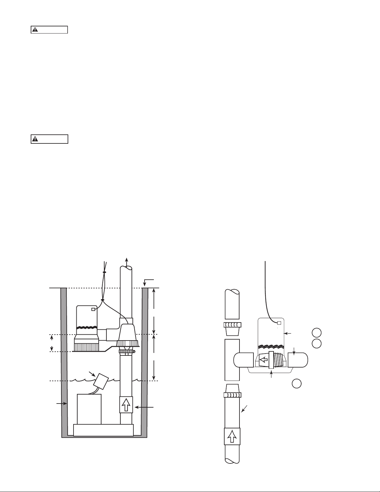
1. Fill sump until primary pump turns on. Mark this
level as “Normal High Water”.
2. When installing the pump, mount the centerline of
the tee inlet at least 2 inches above the normal high
water level.
3. Check that the location of the tee is at least 2 inches
below the top of the sump.
4. Make sure the installation will not interfere with the
primary sump pump operation as follows:
(A) Back up pump must not interfere with primary
pump float switch swing.
(B) Normal high water level must not be high
enough to start the back-up pump.
(C) Install a check valve in the main sump pump
discharge pipe below the back-up pump tee.
Flow in this pipe must be away from the primary
pump. DO NOT INSTALL IT BACKWARDS!
This valve will prevent flow from the back-up
pump back to the sump during battery powered
operation.
5. Cut rigid discharge pipe from primary sump pump
to length, use PVC piping. Tee supplied is 1½" slip
fit; if necessary use 1¼" bushings supplied. Do not
glue the tee until all parts have been trial
fitted and aligned.
1.6 REF.
SUMP
BACK UP
PUMP
FLOAT
SW
*PRIMARY
PUMP
FIGURE 1
Standard Installation
1½
MAX.
SW
1½
MAX.
TOP OF SUMP
2" MIN.
C
L
2" MIN.
“ON”
POSITION
(Primary pump
normal high
water level)
CHECK VALVE
Must be
installed
to prevent
recirculation
into sump.
TEE
PUMP
TEE
CHECK
pump
CHECK
VALV E
PRIMARY
DISCHARGE
PIPE
VALV E
FIGURE 2
Assembly Details
PUMP
ELBOW
11
3
12
4
Page 5
WARNING
CAUTION
WARNING
6. Thread check valve tightly into the elbow provided
and plug the pump discharge into the other end of
the elbow. Secure with hose clamp. Slip the plain end
of the check valve into the side socket of the tee.
7. Install the float switch on the stainless steel bracket
provided and attach the bracket as shown.
Adjust bracket to support pump/switch assembly to
approximately level position.
8. Check for clearance to all working parts of the
primary and back-up pump systems.
9. Remove pump assembly from tee. Remove tee
from pump.
10. Using PVC cement, permanently install the tee on
the discharge pipe, according to the PVC cement
instructions.
Hazardous Fumes. Follow cement
manufacturer’s instructions. Use PVC
cement only in a well ventilated area
away from fire or flame.
11. Reinstall switch/bracket assembly.
12. Using PVC cement, permanently install the pump
assembly by cementing the check valve in the tee side
socket, with the pump base approximately level.
13. Adjust the switch/bracket assembly to support the
pump. Tighten the clamp.
14. Make sure battery is fully charged: then check
operation by disconnecting power to the primary
sump pump and filling sump until the battery
operated pump starts. Run pump through one
complete cycle.
15. Operation may be checked at any time by rotating
the float switch knob or ribbed wheel (4) pivots to
turn on the pump.
The liquid sound you hear in the float
portion of the switch is mercury, not
water, and should be disposed of properly. If you cannot arrange for proper
disposal, the product may be returned
for disposal to place of purchase.
ELECTRICAL CONNECTIONS
Hazardous Voltage. Can cause serious
or fatal electrical shock. Review safety
instructions before operating charger.
Do not modify cord or plug.
CHARGER/BATTERY INSTALLATION
NOTICE: Alarm will sound when charger is first
connected to battery. Press ALARM TEST/
RESET button on charger. If alarm continues
to sound, disconnect one charger lead from
the battery and reconnect it. Press ALARM
TEST/RESET again; alarm will stop
sounding.
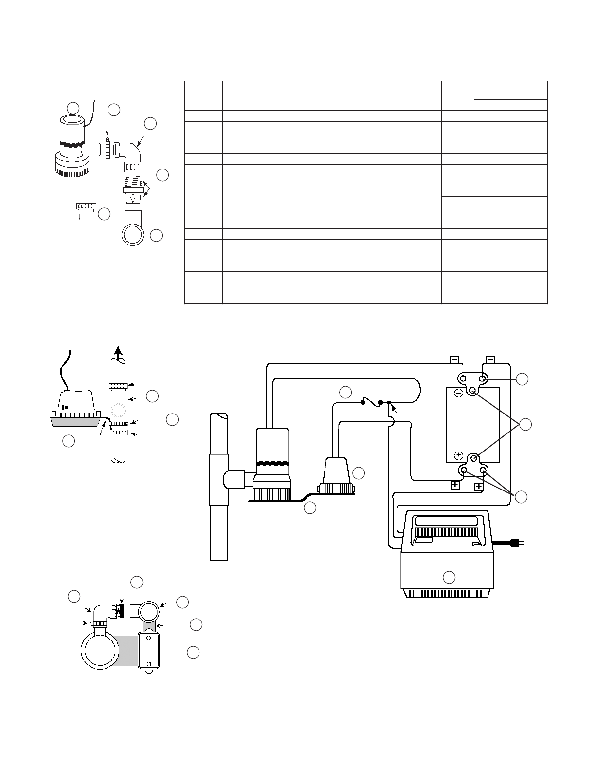
1. Connect charger as shown in Figure 3.
A. Connect Positive (+) lead from charger to
positive battery terminal.
B. Connect (–) lead from charger to negative
battery terminal.
C. Connect the third (blue) lead from the charger to
the blue tap on the brown pump wire just before
the fuse holder.
D. Put the 15 Amp fuse into ½ of the fuse holder
and connect the second half of the fuse holder.
E. Connect the black pump wire to the Negative
battery terminal.
F. Connect the gray switch wire marked + to the
Positive battery terminal.
2. Plug in power cord to a 115-125 Volt AC outlet
delivering at least 2 amps. Do not use a switch
controlled outlet. Mark circuit in main power panel
“Backup sump pump power supply; do not turn off”.
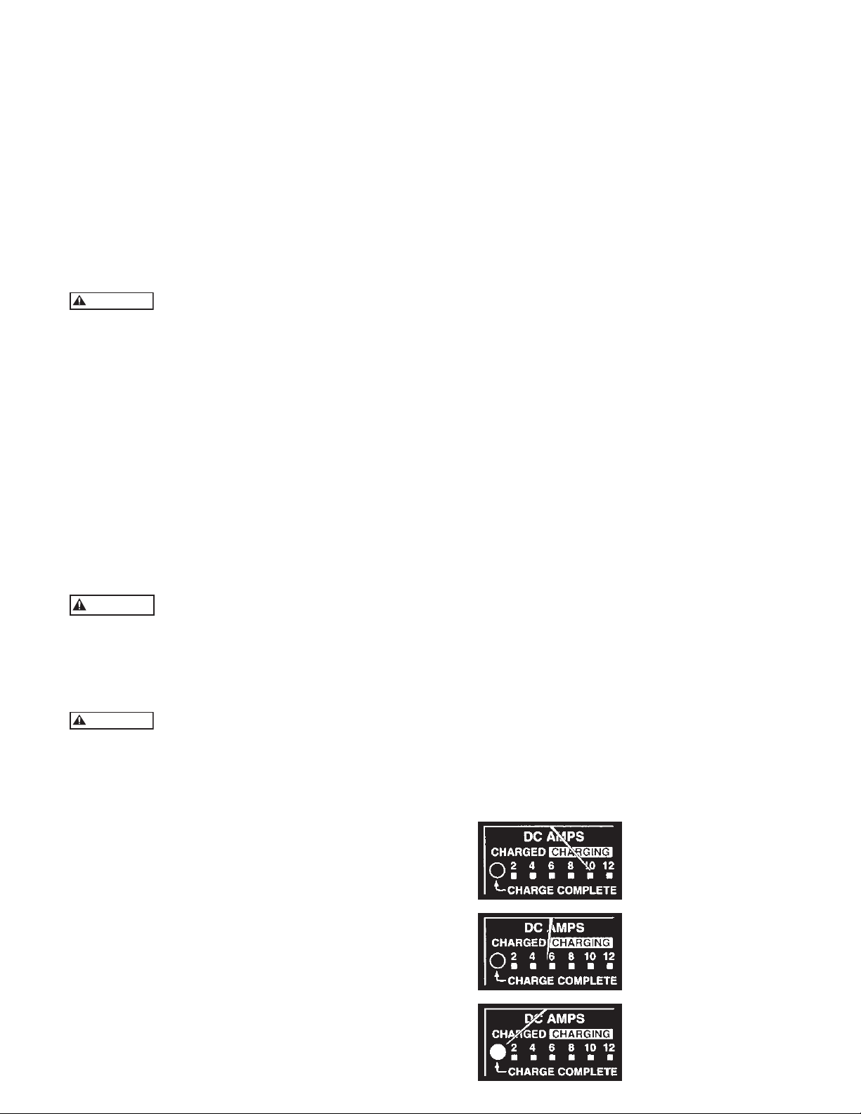
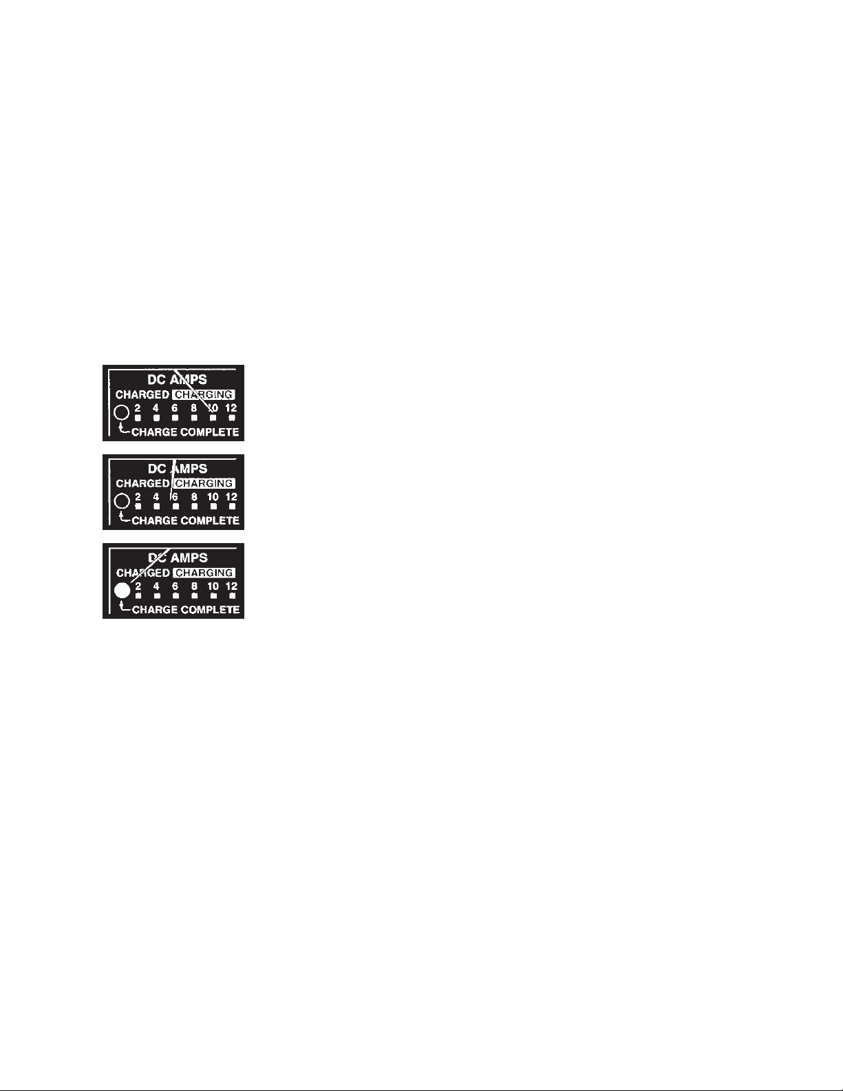
3. With charger properly connected and plugged in, the
panel on the front of the charger will appear as in
one of the following:
A. If battery is dead, charger will supply about
10 amps power (see Figure 3A).
B. If battery is near full charge, charger will deliver
about 5 amps power (see figure 3B).
C. If battery is fully charged, charging current will
be 0 amps and green LED lamp will be lighted
(see figure 3C).
4. The charger is equipped with a self-resetting circuit
breaker which protects it from temporary overloads.
In case of an overload, the circuit breaker will open.
It automatically resets after a short cool-down
period. In some conditions where the overload is
extended the breaker will cycle, repeating the open/
reset process indefinitely. When this happens,
normally the charger will emit a clicking sound as
the breaker opens and resets.
NOTICE: If the clicking sound continues for more
than 30 minutes or so, check for reversed
charger connections to the battery and for
shorted cells in the battery.
BATTERY MAINTENANCE
NOTICE: To protect battery case from chipping and
gouging, do not let battery sit on concrete
floor (plywood, 2x4’s, etc.). Always install
battery in a dry location that is protected
from flooding.
1. Unplug battery charger.
2. On batteries with removable top caps, measure
specific gravity of electrolyte. Use a hydrometer
(available at auto parts stores). If the specific gravity
of any cell is less than 1.225 or if there is more than
.050 variation between cells, replace the battery.
3. Check electrolyte level and refill as needed.
4. Check battery terminals and clamps for tightness and
corrosion. Clean and tighten as needed.
5. Plug in battery charger.
FIGURE 3 –
Battery Backup
3A.
3B.
Control Panel
A. Battery depleted –
charging current
10 Amps.
B. Battery nearly
charged – current
about 5 Amps.
C. Charge complete –
current 0 amps,
LED lights up.
3C.
5
Page 6

REPAIR PARTS
3
pump
1¼"
REDUCING
BUSHINGS
(2) if required
SWITCH
14
HOSE CLAMP
1½"
BRACKET
13
2
12
ELBOW
11
CHECK
VALVE
1½
TEE
1
IF REQUIRED
1
TEE
(opening on other side)
CLAMP
IF REQUIRED
Item
Number Required SPBB SPBB2
1 Tee, 1½" Socket Thermoplastic 1 6K146
2 Reducing Bushing, 1½" x 1¼" Thermoplastic 2 4K499
3 Pump – 2000GPH or 3700GPH Varies 1 9K318 9K499
4 Float Switch Assembly — 1 9K319
5 Fuse Holder — 1 9K320
6 Fuse - 15 Amps/25 Amps — 1 9K321 9K565
1 9K322
2 9K324
3 9K325
8 Terminals - Top Post Battery — 2 9K326
9 Battery Case Thermoplastic 1 9K327
10 Charger Assembly — 1 9K328
11 Check Valve - 1" MPT Thermoplastic 1 6K147 6K174
12 Elbow - 1" FPT Thermoplastic 1 6K148 6K175
13 Hose Clamp — 1 4K497
14 Pump / Switch Bracket — 1 9K329
15 Hose Clamp — 1 4K498
15
Part Description Material
7 Wire Terminals —
BLACK
BROWN
FUSE HOLDER
5
GRAY
pump
FUSE
BLUE
Quantity Repair Part Repair Part
1 9K323
NEGATIVE
CONNECTORS
BATTERY
105 AMP
MIN.
POSITIVE
7
8
6
ELBOW
HOSE
CLAMP
12
pump
11
CHECK VALVE
TEE
BRACKET
SWITCH
4
SWITCH
14
1
14
4
FIGURE 4
GRAY
BLACK/WHITE
BLACK
CHARGER
10
7
Page 7

TROUBLESHOOTING
Pump won’t run:
1. Check all connections.
2. Check for low or defective battery.
3. Check that automatic switch is operating properly.
4. Blown fuse in switch circuit. Unplug pump and re
move the strainer. Check to see if impeller is free
to turn. If impeller is locked remove the obstruction.
Replace strainer and fuse.
Motor hums but pump won’t run:
1. Check for low or defective battery.
Pump runs but pumps very little or no water:
1. Make sure a check valve is installed and
functioning between primary pump discharge and
backup sump pump tee.
2. Check for obstruction in discharge pipe.
3. Discharge pipe length and/or height exceeds capacity
of pump. See Table 1 for pump capacity.
4. Check for low or defective battery.
5. Drill a 1⁄16 to 1⁄8 inch diameter vent hole between
pump discharge and check valve.
Pump cycles too frequently:
1. Main check valve located between discharge of
primary pump and the backup sump pump tee or
check valve not installed or working properly. Install
or repair as required.
NOTE:
“Deep Cycle Marine” batteries are different
than marine and automotive batteries!
7
Page 8

This warranty applies to all water systems pumps manufactured by Red Jacket Water Products.
Any part or parts found to be defective within the warranty period shall be replaced at no charge to the dealer during the warranty period. The war-
ranty period shall exist for a period of twelve (12) months from date of installation or eighteen (18) months from date of manufacture, whichever
period is shorter.
A dealer who believes that a warranty claim exists must contact the authorized Red Jacket Water Products distributor from whom the pump was
purchased and furnish complete details regarding the claim. The distributor is authorized to adjust any warranty claims utilizing the Red Jacket Water
Products Customer Service Department.
The warranty excludes:
(a) Labor, transportation and related costs incurred by the dealer;
(b) Reinstallation costs of repaired equipment;
(c) Reinstallation costs of replacement equipment;
(d) Consequential damages of any kind; and,
(e) Reimbursement for loss caused by interruption of service.
For purposes of this warranty, the following terms have these definitions:
(1) “Distributor” means any individual, partnership, corporation, association, or other legal relationship that stands between Red Jacket Water Products
and the dealer in purchases, consignments or contracts for sale of the subject pumps.
(2) “Dealer” means any individual, partnership, corporation, association, or other legal relationship which engages in the business of selling or leasing
pumps to customers.
(3) “Customer” means any entity who buys or leases the subject pumps from a dealer. The “customer” may mean an individual, partnership, corpora-
tion, limited liability company, association or other legal entity which may engage in any type of business.
THIS WARRANTY EXTENDS TO THE DEALER ONLY.
RED JACKET WATER PRODUCTS LIMITED WARRANTY
Xylem, Inc.
2881 East Bayard Street Ext., Suite A
Seneca Falls, NY 13148
Phone: (866) 325-4210
Fax: (888) 322-5877
www.xyleminc.com/brands/redjacketwaterproducts
Red Jacket Water Products is a trademark of Xylem Inc. or one of its subsidiaries.
© 2012 Xylem Inc. IM186 Revision Number 3 July 2012
Page 9

MANUAL DE INSTRUCCIÓN
IM186
Bomba de sumidero
de reserva a batería
MANUAL DE INSTALACIÓN, OPERACIÓN Y PARTES
Page 10

Índice
TEMA PÁGINA
Instrucciones de seguridad ...........................................................................................................................................11
Herramientas y materiales básicos necesarios ...............................................................................................................11
Información general ....................................................................................................................................................11
Funcionamiento del cargador ......................................................................................................................................11
Requisitos para la batería .............................................................................................................................................12
Instalación y funcionamiento de la bomba ...................................................................................................................12
Conexiones eléctricas ..................................................................................................................................................13
Instalación de cargador/batería ....................................................................................................................................13
Mantenimiento de la batería ........................................................................................................................................14
Localización de fallas ...................................................................................................................................................14
Partes de reparación ....................................................................................................................................................15
Garantía limitada .........................................................................................................................................................16
Información para el propietario
Número de modelo de la bomba:
Número de serie de la bomba:
Número de modelo de control:
Representante:
Número telefónico del representante:
Fecha de compra: Instalación:
10
Page 11

NORMAS PARA UNA INSTALACIÓN Y OPERACIÓN SEGURAS
Lea y siga atentamente todas las instrucciones de seguridad de este manual o del sistema.
Éste es un símbolo de alerta de seguridad. Cuando vea este símbolo sobre la
bomba o en este manual, localice una
de las siguientes palabras y esté alerta
ante posibles lesiones personales.
PELIGRO
Advierte sobre los peligros que, si se
ignoran, PROVOCARÁN lesiones
graves, muerte o daños significativos a
la propiedad.
ADVERTENCIA
Advierte sobre los peligros que, si
se ignoran, PUEDEN PROVOCAR
lesiones graves o daños significativos a
la propiedad.
PRECAUCIÓN
Advierte sobre los peligros que, si se
ignoran, PROVOCARÁN o PUEDEN
PROVOCAR lesiones menores o daños
a la propiedad.
La palabra AVISO indica que existen instrucciones
especiales e importantes pero que no están relacionadas
con el peligro.
1. Para evitar lesiones físicas de gravedad y daños a
la propiedad, lea atentamente las instrucciones de
seguridad antes de instalar la bomba.
2. Cuando instale una bomba, ajústese a las normas
locales y/o nacionales relacionadas con la plomería y
la electricidad. Se recomienda el uso de un
interruptor de circuito con cable a tierra (del inglés,
GFCI) para todos los aparatos eléctricos sumergibles.
3. Utilice esta bomba de sumidero sólo de reserva para
aplicarla en residencias. No está diseñada para su uso
como bomba de sumidero principal.
ADVERTENCIA
Voltaje peligroso. Puede provocar una
descarga eléctrica importante o fatal.
4. No conecte o desconecte un cargador de batería
cuando se encuentre parado sobre un piso húmedo
o sobre agua. Asegúrese de que una de sus manos
esté libre cuando conecte o desconecte el cargador.
Si el piso del sótano está mojado, desconecte la
energía eléctrica que se dirige al sótano antes de
caminar por esa superficie.
5. No levante la bomba con un cable eléctrico.
6. Bombee agua sólo con esta bomba.
7. La bomba se encuentra lubricada de fábrica. No
intente lubricarla.
8. Mantenga el cargador de la batería y su gabinete en
un lugar seco, fresco y bien ventilado.
9. Para evitar el peligro de incendio o explosión, man
tenga las chispas y llamas lejos de la batería.
ADVERTENCIA
El ácido de la batería es corrosivo.
10. No derrame el ácido sobre la piel, ropa o sobre el
cargador de la batería. Utilice un protector para sus
ojos cuando trabaje con la batería.
11. La distancia máxima de bombeo vertical es de
15 pies (4,6 m.).
12. Asegúrese que la bomba esté libre de suciedad.
HERRAMIENTAS Y MATERIALES BÁSICOS
NECESARIOS
Llaves para tubos, destornillador, sierra para metales,
llave inglesa ajustable, cinta Teflón, cuchillo, batería de
12 voltios, cemento PVC, válvula de retención de la
bomba principal (si no está instalada).
INFORMACIÓN GENERAL
El sistema de sumidero de reserva a batería no reemplaza
a la bomba de sumidero principal. Está diseñada como
una bomba de reserva para sustituir a la bomba principal
en caso de emergencia durante un corte de energía o en
otros casos que impiden su funcionamiento normal. No
la utilice para bombear líquidos o productos químicos
inflamables.
Mantenga seco el cargador de batería y protéjalo de
daños. Si se agota la batería del sistema (por ejemplo, durante un corte de energía prolongado), podrá utilizar, en
caso de emergencia, la batería de su auto provisoriamente
para sustituirla. Asegúrese de reemplazar el sistema de
batería lo antes posible.
FUNCIONAMIENTO DEL CARGADOR
La bomba de reserva comenzará a funcionar automáticamente cuando el nivel de agua del sumidero se eleve
lo suficiente como para disparar el interruptor de flotador. Luego de un retraso de alrededor de 4 segundos,
sonará una alarma. Apague la alarma presionando el
botón ALARM TEST/RESET (PRUEBA DE ALARMA/
REINICIO). Si la operación es normal (cuando actúa el
interruptor), la alarma permanecerá bloqueada hasta 4
segundos luego de que el interruptor del flotador haya
descendido hasta la posición OFF. Posteriormente, el
ciclo comenzará de nuevo.
Cuando no suene la alarma, puede controlarla presionando el botón ALARM TEST/RESET. En ese caso, la alarma
sonará mientras el botón permanezca hacia abajo.
Si suena la alarma, controle el funcionamiento de la
bomba principal, ya que es posible que necesite servicio.
Si la operación de reserva de batería se debe a una descarga eléctrica, la alarma sonará. No obstante, es posible
que la bomba principal no requiera de servicio.
El cargador de la batería puede mantener la bomba en
funcionamiento y cargar la batería al mismo tiempo
mientras no se interrumpa la energía que se dirige al
cargador. Si se interrumpe el paso de energía al cargador,
el tiempo de operación de la bomba de reserva dependerá de la capacidad de amperes por hora de la batería
utilizada.
Los períodos de operación prolongados (por ejemplo,
durante un corte de energía prolongado) pueden agotar
la batería. No obstante, una vez que la carga se agote,
generalmente se recargará por sí sola y durará el tiempo
suficiente para que el cargador arranque. El cargador de
la batería comenzará a recargar la batería nuevamente
siempre que ésta cuente con una carga de por lo menos
½ voltios.
Cuando retorne la energía, el cargador automáticamente
recargará la batería en forma completa en alrededor de
dos horas.
AVISO: Si la batería no ha alcanzado un voltaje satis factorio luego de 24 horas de carga, sonará la
alarma. En este caso la alarma no podrá reinici arse. Las posibles causas de este problema son:
11
Page 12

PROBLEMA ACCIÓN
Opera la bomba de reserva Push ‘Reset’. Check main pump
Corte de energía de Desconecte el cargador de la
más de 24 hs batería. Comuníquese con la
empresa de energía.
Carga continua por más Desconecte el cargador de la
de 24 hs. batería. Controle si la batería
presenta un desperfecto.
Conexión floja o cargador Desconecte el cargador de la
sin energía batería. Controle el enchufe,
receptáculo y energía en el
interruptor principal.
La alarma puede reiniciarse cuando se restaura la energía o se cambia
la batería.
REQUISITOS PARA LA BATERÍA
ADVERTENCIA
Corriente eléctrica peligrosa.
Si las terminales de la batería se encuentran en cortocircuito pueden provocar quemaduras de gravedad e iniciar
un incendio. Instale la batería en el gabinete. Para evitar
un cortocircuito accidental en las terminales de la batería,
sujete la tapa firmemente sobre el gabinete de la batería.
No deje la batería descubierta. No permita que los niños
jueguen cerca del sector donde se encuentra la bomba de
sumidero.
La bomba de sumidero de reserva depende de la energía
de la batería utilizada. Cuanto mejor sea la condición de
la batería, mejor será el rendimiento de la bomba.
Recomendamos el uso de una Batería Marina de ciclo
profundo de 105 amperes.
Esta batería funciona durante muchas horas y se mantiene en buenas condiciones durante largos períodos de
poco uso o uso nulo.
PRECAUCIÓN
No se recomienda el uso de una batería
estándar marina o de automóvil. Una
batería de automóvil puede requerir
una recarga luego de sólo 1 o 2 horas
de uso continuo, y los ciclos reiterados
de recarga pueden provocar una falla
temprana en la placa de la batería.
Utilice sólo una batería nueva con carga
completa del tamaño correcto para su
gabinete (tamaño máximo de 125⁄8"
de largo, 7" de ancho y 93⁄8" de altura
(320,7 mm x 177,8 mm x 238 mm)
incluidas las terminales).
INSTALACIÓN Y FUNCIONAMIENTO DE LA BOMBA
AVISO Recomendamos una prueba de ajuste de todos
los componentes antes de fijar cualquiera de
ellos. Esto le permitirá controlar la distancia de
la altura de montaje del interruptor flotante de
la bomba, etc., mientras aún se pueden realizar
ajustes fácilmente
1. Cargue el sumidero hasta que arranque la bomba
principal. Marque este nivel como la “altura normal
de agua”.
2. Cuando instale la bomba, monte la línea central de
la boca de entrada en T por lo menos a 2 pulgadas
por encima del nivel normal de agua.
3. Verifique que la ubicación de la entrada en T se
encuentre por lo menos a 2 pulgadas por debajo de
la parte superior del sumidero.
REF. 1,6
BOMBA
BOMBA DE
RESERVA
INTERR.
FLOTANTE
*BOMBA
PRINCIPAL
FIGURA 1
Instalación estándar
MÁX.
1 ½
INTERR.
MÁX.
1 ½
PARTE SUP.
DE LA BOMBA
MIN. 2"
C
T
L
MIN. 2"
POSICIÓN
“ON” (Nivel de agua
normal de la bomba
principal)
VÁLVULA DE
RETENCIÓN
Debe instalarse
para evitar la
recirculación al
sumidero.
BOCA DE
PUMP
ENTRADA
EN T
bomba
VÁLVULA DE
RETENCIÓN
TUBO DE
DESCARGA
PRINCIPAL
VÁLVULA DE
RETENCIÓN
BOMBA
CODILLO
11
3
12
12
FIGURA 2
Detalles de montaje
Page 13

4. Asegúrese de que la instalación no interfiera con el
funcionamiento de la bomba de sumidero principal
mediante los siguientes pasos:
(A) La bomba de reserva no debe interferir con
la oscilación del interruptor flotante de la
bomba principal.
(B) El nivel normal de agua no debe ser tan alto
como para iniciar el funcionamiento de la
bomba de reserva.
(C) Instale una válvula de retención en el tubo de
descarga de la bomba de sumidero debajo de
la entrada en T de la bomba de reserva. El
flujo en este tubo debe estar lejos de la bomba
principal. ¡NO LA INSTALE EN FORMA
INVERSA! Esta válvula evitará que el flujo de
la bomba de reserva vuelva al del sumidero
durante la operación de recarga de la batería.
5. Corte a lo largo el tubo rígido de descarga de la
bomba de sumidero principal. Utilice tubos de
PVC. La boca de entrada en T suministrada es de
1½ pulgada con ajuste deslizante. Si es necesario
utilice las boquillas de (1)¼" que se suministran. No
pegue la entrada en T hasta que se haya probado el
ajuste y alineación de todas las partes.
6. Enrosque la válvula de retención bien ajustada
dentro del codillo que se suministra y conecte la
descarga de la bomba dentro del otro extremo del
mismo. Asegure con abrazadera de manguera.
Deslice el extremo plano de la válvula de retención
dentro del enchufe lateral de la entrada en T.
7. Instale el interruptor flotante sobre el soporte de
acero inoxidable que se suministra y sujete el soporte
como se muestra más abajo: Ajuste el soporte para
sostener el montaje de bomba/interruptor
aproximadamente a nivel de posición.
8. Verifique la distancia de todas las partes efectivas
de los sistemas de bomba principal y de reserva.
9. Quite el montaje de la bomba desde la entrada en T.
Quite la entrada en T de la bomba.
10. Utilice cemento PVC para instalar la entrada en T
de manera permanente en el conducto de descarga,
conforme a las instrucciones del cemento PVC.
ADVERTENCIA
Emanaciones peligrosas. Siga las instrucciones del fabricante deL cemento. Utilice cemento PVC sólo en un área bien
ventilada, lejos del fuego o las llamas.
11. Reinstale el montaje interruptor/soporte.
12. Utilice cemento PVC para instalar de manera
permanente el montaje de la bomba pegando
la válvula de retención en el enchufe lateral de la
entrada en T, con la base de la bomba
aproximadamente nivelada.
13. Ajuste el montaje interruptor/soporte para sostener
la bomba. Ajuste la abrazadera.
14. Asegúrese que la batería esté con carga completa:
luego verifique el funcionamiento desconectando la
energía a la bomba de sumidero principal y cargando
el sumidero hasta que arranque la bomba de funcionamiento a batería. Haga funcionar la bomba hasta
que cumpla un ciclo completo.
15. Puede verificarse el funcionamiento en cualquier
momento girando los pivotes (4) gastados del
interruptor flotante para encender la bomba.
PRECAUCIÓN
El sonido de líquido que se oye en la
parte flotante del interruptor es mercurio, no agua, y debe ser eliminado
correctamente. Si no puede hacerlo así,
podrá devolver el producto para su eliminación al comercio donde lo adquirió.
CONEXIONES ELÉCTRICAS
ADVERTENCIA
Voltaje peligroso. Puede causar descarga
eléctrica importante o fatal. Revise las
instrucciones de seguridad antes de
poner en funcionamiento el cargador.
No modifique el cable ni el enchufe.
INSTALACIÓN DEL CARGADOR/BATERÍA
AVISO: Cuando se conecte por primera vez el carga-
dor a la batería sonará la alarma. Presione el
botón ALARM TEST/RESET en el cargador.
Si la alarma continúa sonando, desconecte un
cable del cargador de la batería y reconéctelo.
Presione ALARM TEST/RESET nuevamente,
la alarma se detendrá.
1. Conecte el cargador como se muestra en la Figura 3.
A. Conecte el cable Positivo (+) desde el cargador a l
a terminal positiva de la batería.
B. Conecte el cable (-) desde el cargador a la terminal
negativa de la batería.
C. Conecte el tercer cable (azul) desde el cargador
a la toma azul sobre el cable marrón de la bomba
justo delante del porta fusible.
D. Coloque el fusible de amperaje 15 dentro de la
½ del porta fusible y conecte la segunda mitad del
porta fusible.
E. Conecte el cable negro de la bomba a la terminal
negativa de la batería.
F. Conecte el cable gris del interruptor marcado
con + a la terminal positiva de la batería.
2. Conecte el cable de energía a una boca de salida
de 115-125 Voltios CA suministrando al menos
2 amperes. No utilice una boca de salida
controlada por interruptor. Marque el circuito en
el panel de potencia principal “Suministro de energía
de la bomba de sumidero de reserva; no lo apague”.
3. Con el cargador correctamente conectado y enchu fado, el panel en el frente del cargador aparecerá
como en uno de los siguientes estados:
A. Si la batería está muerta, el cargador suministrará
una energía de 10 amperes aproximadamente
(ver Figura 3 A).
B. Si la batería está cercana a su carga completa, el
cargador enviará una energía de 5 amperes
aproximadamente (ver Figura 3 B).
C. Si la batería está con carga completa, la corriente
de carga será de 0 amperes y se encenderá la luz
verde del indicador LED (ver Figura 3 C).
4. El cargador está equipado con un disyuntor de
auto-restauración que lo protege de sobrecargas
temporarias. En caso de una sobrecarga, el disyun tor se abrirá. Se restaurará automáticamente luego
de un corto período de enfriamiento. En algunas
condiciones en que la sobrecarga se prolongue, el
disyuntor cumplirá el ciclo, repitiendo el proceso
abrir/reiniciar indefinidamente. Cuando esto ocurre,
el cargador normalmente emitirá un sonido seco a
medida que el disyuntor se abra y se reinicie.
13
Page 14

AVISO: Si el ruido seco continúa por más de 30 minutos,
verifique las conexiones inversas del cargador
a la batería y elementos cortocircuitados en la
misma.
MANTENIMIENTO DE LA BATERÍA
AVISO: Para evitar que la cubierta de la batería se pique
o se raspe, no la apoye sobre un piso de cemento
(madera laminada, 2 x 4 , etc.). Instale siempre
la batería un en lugar seco que esté protegido
contra inundación.
1. Desconecte el cargador de la batería.
2. En baterías con tapa superior removible, mida el
peso específico del electrolito. Utilice un hidrómetro
(puede encontrarlo en comercios de auto partes). Si
el peso específico de cualquier elemento es menor a
1,225 o si hay una variación de más de 0,050 entre
elementos, reemplace la batería.
3. Verifique el nivel de electrolito y vuelva a cargarla
según sea necesario.
4. Verifique las terminales y abrazaderas de las baterías
para controlar la firmeza y corrosión. Limpie y ajuste
según sea necesario.
5. Enchufe el cargador de la batería.
FIGURA 3- Panel de
control de la batería
de reserva
3A.
3B.
3C.
A. Batería agotada:
corriente de carga
10 amperes.
B. Batería casi cargada:
corriente de
aproximadamente
5 amperes.
C. Carga completa:
corriente de
0 amperes, luces
del indicador LED
encendidas.
LOCALIZACIÓN DE FALLAS
La bomba no funciona:
1. Verifique todas las conexiones.
2. Verifique que la batería no esté con carga baja o defectuosa.
3. Verifique que el interruptor automático gire hacia arriba y hacia abajo sin dificultad.
4. Fusible fundido en el interruptor. Desconecte la
bomba y quite el filtro. Verifique que el impulsor gire
sin dificultad. Si el impulsor está bloqueado quite la
obstrucción. Reemplace el filtro y el fusible.
El motor zumba pero la bomba no funciona:
1. Verifique que la batería no esté con carga baja o defectuosa.
La bomba funciona pero bombea muy poca agua o nada:
1. Asegúrese que esté instalada una válvula de retención y
que funcione entre la descarga de la bomba principal y
la entrada en T de la bomba de sumidero de reserva.
2. Verifique que no haya una obstrucción en el tubo de
descarga.
3. La longitud y/o altura del tubo de descarga excede la
capacidad de la bomba. Vea la Tabla 1 para conocer la
capacidad de la bomba.
4. Verifique que la batería no esté con carga baja o defectuosa.
5. Perfore un orificio de ventilación de 1/16 a 1/8 de
diámetro entre la descarga de la bomba y la válvula de
retención.
La bomba realiza ciclos demasiado seguidos:
1. La válvula de retención principal ubicada entre la
descarga de la bomba principal y la entrada en T de la
bomba de sumidero de reserva, o la válvula de retención no están instaladas correctamente o no funcionan
de manera apropiada. Instale una nueva o repare según
sea necesario.
NOTA: Las baterías “marinas de ciclo profundo” son
diferentes a las baterías marinas y de automóviles.
14
Page 15

PARTES DE REPARACIÓN
ABRAZADERA DE
1½"
13
MANGUERA
2
12
CODILLO
ENTRADA EN T
11
VÁLVULA DE
RETENCIÓN
1½
1
3
bomba
1¼"
BOQUILLA DE REDUCCIÓN
(2) si es necesario
Número de orden
Número
de artículo necesaria de reparación
Descripción de la parte Material
Cantidad de la parte
SPBB SPBB2
1 TEntrada T, Enchufe 1½" Termoplástico 1 6K146
2 Boquilla de reducción,1½" x 1¼" Termoplástico 2 4K499
3 Bomba – 2000GPH or 3700GPH Varía 1 9K318 9K499
4 Unidad interruptor flotante — 1 9K319
5 Porta fusible — 1 9K320
6 Fusible-15 amp./25 amp. — 1 9K321 9K565
1 9K322
7 Terminales de cable —
2 9K324
1 9K323
3 9K325
8 Terminales-Batería de pilote superior — 2 9K326
9 Cubierta de batería Termoplástico 1 9K327
10 Montaje del Cargador — 1 9K328
11 Válvula de retención 1" MPT Termoplástico 1 6K147 6K174
12 Codillo-1" FPT Termoplástico 1 6K148 6K175
13 Abrazadera de manguera — 1 4K497
14 Bomba/Disyuntor — 1 9K329
15 Abrazadera de manguera — 1 4K498
INTERRUPTOR
DISYUNTOR
14
12
CODILLO
ABRAZADERA DE
MANGUERA
SI ES NECESARIO
T
(apertura en otro costado)
ABRAZADERA
SI ES NECESARIO
11
VÁLVULA DE RETENCIÓN
1
15
T
1
DISYUNTOR
14
NEGRO
Bomba
MARRÓN
14
PORTA FUSIBLE
5
GRIS
4
INTERRUPTOR
FUSIBLE
FIGURA 4
CONECTORES
AZUL
GRIS
NEGRO/BLANCO
NEGATIVO
POSITIVO
NEGRO
CARGADOR
10
BATERÍA
105 AMP
MÍN.
7
8
7
BOMBA
INTERRUPTOR
4
15
Page 16

GARANTÍA LIMITADA DE RED JACKET WATER PRODUCTS
Esta garantía es aplicable a todas las bombas para sistemas de agua fabricadas por Red Jacket Water Products.
Toda parte o partes que resultaren defectuosas dentro del período de garantía serán reemplazadas durante dicho período de garantía sin cargo para el
comerciante. Tal período de garantía se extiende por doce (12) meses a partir de la fecha de instalación, o dieciocho (18) meses a partir de la fecha de
fabricación, la que se cumpla primero.
El comerciante que considere que existe lugar a un reclamo de garantía deberá ponerse en contacto con el distribuidor autorizado de Red Jacket Water
Products del cual adquiriera la bomba y brindar información detallada con respecto al reclamo. El distribuidor está autorizado a liquidar todos los
reclamos por garantía a través del Departamento de Servicios a Clientes de Red Jacket Water Products.
La presente garantía excluye:
(a) La mano de obra, el transporte y los costos relacionados en los que incurra el comerciante;
(b) los costos de reinstalación del equipo reparado;
(c) los costos de reinstalación del equipo reemplazado;
(d) daños emergentes de cualquier naturaleza; y
(e) el reembolso de cualquier pérdida causada por la interrupción del servicio.
A los fines de esta garantía, los términos “Distribuidor”, “Comerciante” y “Cliente” se definen como sigue:
(1) “Distribuidor” es aquel individuo, sociedad, corporación, asociación u otra entidad jurídica que opera entre Red Jacket Water Products y el comer-
ciante para la compra, consignación o contratos de venta de las bombas en cuestión.
(2) “Comerciante” es todo individuo, sociedad, corporación asociación u otra entidad jurídica que realiza negocios de venta o alquiler-venta (leasing)
de bombas a los clientes.
(3) “Cliente” es toda entidad que compra o adquiere bajo la modalidad de leasing las bombas en cuestión de un comerciante. El término “cliente”
puede significar un individuo, sociedad, corporación, sociedad de responsabilidad limitada, asociación o cualquier otra entidad jurídica con actividades en cualquier tipo de negocios.
LA PRESENTE GARANTÍA SE EXTIENDE AL COMERCIANTE ÚNICAMENTE.
Xylem, Inc.
2881 East Bayard Street Ext., Suite A
Seneca Falls, NY 13148
Teléfono: (866) 325-4210
Fax: (888) 322-5877
www.xyleminc.com/brands/redjacketwaterproducts
Red Jacket Water Products son una marca registrada de Xylem Inc. o una de sus filiales.
© 2012 Xylem Inc. IM186 Revisión Número 3 Julio 2012
Page 17

MANUEL D'UTILISATION
IM186
Pompe de puisard
de secours à batterie
DIRECTIVES D’INSTALLATION, D’UTILISATION ET D’ENTRETIEN
Page 18

Table des matières
SUJET PAGE
Règles de sécurité pour l’installation et l’utilisation .........................................................................................................19
Outillage et matériel de base requis ................................................................................................................................19
Informations générales ..................................................................................................................................................19
Fonctionnement de la pompe et du chargeur ..................................................................................................................19
Exigences relatives à la batterie ......................................................................................................................................20
Installation et utilisation de la pompe .............................................................................................................................20
Raccordement électrique ...............................................................................................................................................21
Branchement de la batterie et du chargeur ......................................................................................................................21
Entretien de la batterie ..................................................................................................................................................22
Diagnostic des anomalies ...............................................................................................................................................22
Pièces de rechange ........................................................................................................................................................23
Garantie limitée ............................................................................................................................................................24
Informations pour le propriétaire
Numéro de modèle de la pompe :
Numéro de série de la pompe :
No de modèle de la commande :
Détaillant :
No de téléphone du détaillant :
Date d’achat : d’installation :
18
Page 19
RÈGLES DE SÉCURITÉ POUR L’INSTALLATION ET L’UTILISATION
DANGER
DANGER
Lire et suivre avec soin toutes les consignes de sécurité
figurant dans le manuel et sur les éléments du système.
Le mot AVIS sert à énoncer des directives spéciales im-
portantes, non liées à des risques.
1. Afin de prévenir les dommages matériels et
les blessures graves, lire les consignes de sécurité
avant d’installer la pompe.
2. Suivre les prescriptions des codes provinciaux ou
nationaux de la plomberie et de l’électricité
pertinents, ainsi que les règlements locaux. L’usage
d’un disjoncteur de fuite à la terre est recommandé
pour tout appareil électrique immergé.
3. Employer la pompe uniquement comme pompe de
puisard domestique de secours, car elle n’est pas
conçue pour servir de pompe de puisard principale.
4. Ne pas brancher ni débrancher le chargeur de
batterie si l’on est dans l’eau ou sur un plancher
mouillé. S’assurer qu’une main est libre quand on
branche ou débranche le chargeur. Si le plancher
du sous-sol est mouillé, couper l’alimentation en
courant du sous-sol avant de marcher sur le plancher.
5. Ne pas lever la pompe par son cordon
d’alimentation.
6. Ne pomper que de l’eau avec la pompe de secours.
7. La pompe est lubrifiée à vie. Ne pas essayer de la
lubrifier !
8. Garder le chargeur et le coffre à batterie en un lieu
sec, frais et bien aéré.
9. Pour prévenir les dangers d’incendie ou d’explosion,
maintenir la batterie loin des étincelles
et des flammes.
10. Ne pas renverser d’électrolyte sur la peau, sur les
vêtements ni sur le chargeur. Porter des lunettes de
sécurité pour travailler sur la batterie.
11. La hauteur de refoulement maximale de la pompe
est de 4,6 m (15 pi).
12. S’assurer que les corps étrangers ne peuvent être
aspirés dans la pompe.
AVERTISSEMENT
ATTENTION
AVERTISSEMENT
Le symbole ci-contre est un SYMBOLE
DE SÉCURITÉ employé pour signaler
les mots-indicateurs dont on trouvera
la description ci-dessous. Sa présence
sert à attirer l’attention afin d’éviter les
blessures !
Prévient des risques qui VONT causer
des blessures graves, la mort ou des
dommages matériels importants si l’on
n’en tient pas compte.
Prévient des risques qui, si l’on n’en
tient pas compte, PEUVENT causer
des blessures graves, la mort ou des
dommages matériels importants.
Prévient des risques qui, si l’on n’en
tient pas compte, VONT ou
PEUVENT causer un traumatisme ou
des dommages matériels légers.
Tension dangereuse — peut causer un
choc électrique grave, voire mortel.
L’électrolyte de la batterie est de l’acide
sulfurique, donc corrosif.
OUTILLAGE ET MATÉRIEL DE BASE REQUIS
L’outillage et le matériel suivants sont nécessaires : clés à
tubes, tournevis, scie à métaux, clé à molette, ruban de
Téflon, canif, batterie de 12 V, colle pour polychlorure
de vinyle (PVC), clapet de non-retour (s’il n’y en a pas
d’installé après la pompe principale).
INFORMATIONS GÉNÉRALES
La pompe de puisard de secours à batterie n’est pas conçue pour remplacer la pompe de puisard principale, mais
bien pour servir durant les pannes de courant et autres
défaillances empêchant la pompe principale de fonctionner. Ne pas l’utiliser pour les liquides inflammables ou
chargés chimiquement.
Protéger le chargeur de batterie de l’humidité et des
chocs. Au cours d’une panne de courant ou autre urgence
prolongées épuisant la batterie, on pourra employer temporairement une batterie d’automobile, mais on veillera à
réutiliser la batterie de la pompe dès que possible.
FONCTIONNEMENT DE LA POMPE ET DU
CHARGEUR
La pompe de secours démarrera automatiquement quand
le niveau de l’eau du puisard montera assez pour déclencher le contacteur à flotteur. Après un délai d’environ
quatre (4) secondes, une alarme sonnera. On arrêtera
l’alarme en pressant le bouton ALARME — ESSAI ET
RÉARMEMENT (ALARM TEST/RESET). En fonctionnement normal, l’alarme s’arrêtera environ 4 s après que le
contacteur sera redescendu à sa position d’arrêt (OFF).
Le cycle pourra alors recommencer.
On peut essayer l’alarme en tout temps en pressant
le bouton ALARME — ESSAI ET RÉARMEMENT
(ALARM TEST/RESET).
En cas d’alarme, vérifier le fonctionnement de la pompe
principale, qui pourrait avoir besoin d’entretien, ce qui
est peu probable si l’alarme est due à une panne de courant.
Le chargeur peut faire fonctionner la pompe de secours
et en charger la batterie simultanément tant qu’il est
alimenté en courant. En cas de panne de courant, l’autonomie de la pompe sera proportionnelle à la charge en
ampères-heures (Ah) de la batterie utilisée.
Les longues périodes de fonctionnement (panne de
courant prolongée) peuvent épuiser la batterie. Cependant, une fois la pompe mise hors service, la batterie
pourra normalement se recharger d’elle-même assez pour
produire le ½ V nécessaire à la remise en marche du
chargeur.
Dès que le courant sera rétabli, le chargeur rechargera
automatiquement la batterie, en six heures environ.
AVIS : si la batterie ne fournit pas une tension suffisante
après 24 h de charge, l’alarme sonnera. On ne
pourra alors réarmer le dispositif d’alarme (voir
les anomalies et correctifs en page suivante).
19
Page 20

ANOMALIE CORRECTIF
AVERTISSEMENT
Fonctionnement de la Presser RÉARMEMENT (RESET).
pompe de secours Vérifier la pompe principale.
Panne de courant pendant Débrancher le chargeur d’avec
plus de 24 h la batterie. S’adresser à la
société d’électricité.
Charge de batterie durant Déconnecter le chargeur d’avec
plus de 24 h la batterie. Vérifier si la batterie
est défectueuse.
Connexion lâche ou chargeur Débrancher le chargeur d’avec
sans courant la batterie. Vérifier la fiche du
cordon, la prise murale et le
courant au disjoncteur principal.
Une fois le courant rétabli ou la batterie remplacée, on peut réarmer le
dispositif d’alarme.
EXIGENCES RELATIVES À LA BATTERIE
Courant électrique dangereux
Placer la batterie dans son coffre pour prévenir le courtcircuitage des bornes de batterie et, ainsi, les risques de
brûlure graves et d’incendie. Bien assujettir le couvercle
au coffre avec la sangle de ce dernier. Ne pas laisser la
batterie non couverte ni permettre aux enfants de jouer
près du système de pompage.
Le rendement de la pompe de puisard de secours est
fonction de la batterie alimentant la pompe. Meilleure
sera la batterie, meilleur sera le rendement.
L’usage d’une batterie marine à charge poussée de 105 A
est recommandé.
La batterie recommandée fournit un bon rendement pendant de nombreuses heures et garde bien sa charge quand
la pompe est en attente durant de longues périodes.
ATTENTION
L’emploi d’une batterie d’automobile ou
marine standard avec le chargeur prévu
pour la pompe de secours n’est pas
recommandé. Une batterie d’automobile
peut nécessiter une recharge après une à
deux heures d’usage ininterrompu, et les
cycles de charge répétés peuvent causer
la défaillance prématurée des plaques de
batterie.
Employer uniquement une batterie
neuve, chargée à bloc et pouvant aller
dans le coffre à batterie. Les dimensions
maximales sont : 320,7 mm (125⁄8 po) de
longueur, 177,8 mm (7 po) de largeur et
238 mm (93⁄8 po) de hauteur (avec
les bornes).
INSTALLATION ET UTILISATION DE LA POMPE
AVIS : Afin d’éviter tout problème d’assemblage
éventuel, il est recommandé de vérifier la mise
en place et la hauteur des éléments de tuyauterie
et autres composants, dont le contacteur à
flotteur de la pompe de secours, avant de fixer
les tronçons de tuyauterie avec de la colle.
1. Remplir le puisard d’eau jusqu’à ce que la pompe
principale démarre. Marquer le niveau alors atteint
par l’eau comme étant le « haut niveau d’eau
normal ».
2. Pour mettre la pompe de secours à la bonne hauteur,
en placer l’axe horizontal du té de refoulement à au
moins 2 po au-dessus du haut niveau d’eau normal.
3. S’assurer que le té est à au moins 2 po sous le bord
du puisard.
1,6 po (RÉF.)
PUISARD
POMPE DE
SECOURS
CONTACTEURS
À FLOTTEUR
POMPE
PRINCIPALE
Installation type
FIGURE 1
1½ po
(MAX.)
1½ po
(MAX.)
BORD DU PUISARD
2 po (MIN.)
C
AXE DU TÉ
L
2 po (MIN.)
NIVEAU
DÉMARRAGE
(haut niveau d’eau
normal pour la
pompe principale)
CLAPET DE
NON-RETOUR
(requis pour
empêcher le retour
du liquide dans le
puisard)
pump
TÉ
PUMP
TEE
CLAPET DE
NON-RETOUR
TUYAU DE REFOULEMENT
PRIMARY
DE LA POMPE PRINCIPALE
DISCHARGE
PIPE
CLAPET DE
CHECK
NON-RETOUR
VALV E
FIGURE 2
Détails d’assemblage
CHECK
VALV E
POMPE DE SECOURS
PUMP
COUDE
ELBOW
12
11
3
20
Page 21

4. Vérifier les points A et B suivants et exécuter
la tâche C pour s’assurer que la pompe de secours ne
gênera pas le fonctionnement de la pompe
principale :
A. Le contacteur à flotteur sur câble (de la pompe
principale) doit pouvoir bouger librement.
B. Le haut niveau d’eau normal ne doit pas
atteindre le niveau de démarrage de la pompe
de secours.
C. Poser un clapet de non-retour sur le tuyau
de refoulement de la pompe principale,
au-dessous du té de la pompe de secours, mais
suivant le sens d’écoulement du liquide, indiqué
par la flèche du clapet. NE PAS INSTALLER LE
CLAPET EN SENS INVERSE. Le clapet em pêche le liquide de retourner dans le puisard
durant le fonctionnement de la pompe de
secours.
5. Couper un tronçon de tuyau de refoulement à la
longueur appropriée pour la pompe principale.
Employer du tuyau de polychlorure de vinyle (PVC).
Le té fourni permet un raccordement coulissant de
½ po. Au besoin, employer les raccords réducteurs
de 1½ po à 1¼ po inclus. Ne pas coller le té avant
de s’assurer que l’assemblage et l’alignement de
toutes les pièces sont corrects.
6. Visser le clapet de non-retour à fond sur le coude
fourni (v. illustrations en page 22). Enfiler l’autre
bout du coude sur la tubulure de refoulement de la
pompe et l’assujettir avec un collier de serrage.
Insérer l’extrémité libre du clapet dans la branche
médiane du té.
7. Fixer le contacteur à flotteur sur la ferrure en inox
fournie. Attacher la ferrure au té avec un collier de
serrage. Régler la position de la ferrure pour que la
pompe et le contacteur soient à peu près de niveau.
8. Vérifier si les pièces mobiles du système peuvent
bouger librement.
9. Séparer la pompe de secours et l’ensemble ferrure contacteur d’avec le té, puis enlever le té du tuyau
de refoulement de la pompe principale.
10. Fixer le té au tuyau de refoulement avec de la colle
pour PVC, selon les directives d’utilisation de la
colle.
AVERTISSEMENT
Vapeurs dangereuses. Suivre les directives du fabricant de la colle. Utiliser la
colle uniquement en un lieu bien ventilé,
loin de la flamme.
11. Reposer l’ensemble ferrure-contacteur sur le té.
12. Avec de la colle pour PVC, fixer le clapet de la
pompe de secours à la branche médiane du té tout en
s’assurant que le dessous de la pompe sera à peu près
de niveau.
13. Régler la ferrure pour qu’elle supporte la pompe,
puis assujettir la ferrure avec son collier de serrage.
14. S’assurer que la batterie est chargée à bloc. Vérifier
ensuite si la pompe de secours fonctionne correc tement. Pour ce faire, déconnecter la pompe
principale et remplir le puisard d’eau jusqu’à ce que
la pompe de secours démarre. Laisser la pompe
achever son cycle.
15. À l’aide des molettes du contacteur, on peut faire
pivoter celui-ci pour vérifier le fonctionnement de la
pompe de secours.
ATTENTION
Le son que l’on entendra en faisant pivoter le flotteur est celui du mercure qu’il
contient, produit dangereux que l’on
devrait éliminer correctement. Si l’on
ne peut éliminer soi-même le produit de
façon appropriée, on peut le retourner à
cet effet au vendeur du produit.
RACCORDEMENT ÉLECTRIQUE
AVERTISSEMENT
Tension dangereuse — peut causer un
choc électrique grave, voire mortel.
Relire les consignes de sécurité avant
d’employer le chargeur.
Ne pas modifier le cordon d’alimentation ni la fiche.
BRANCHEMENT DE LA BATTERIE ET DU
CHARGEUR
AVIS : l’alarme sonnera lorsque l’on branchera
le chargeur à la batterie la première fois.
Presser alors le bouton ALARME — ESSAI
ET RÉARMEMENT (ALARM TEST/RESET)
du chargeur. Si l’alarme continue à sonner,
débrancher un conducteur de sortie du chargeur
d’avec la batterie, puis le rebrancher. Appuyer de
nouveau sur le bouton, et l’alarme s’arrêtera.
1. Connecter le chargeur et la batterie comme suit
(v. fig. 4) :
A. Brancher le conducteur positif (+) du chargeur
au connecteur + de la batterie.
B. Connecter le conducteur négatif (–) du chargeur
au connecteur – de la batterie.
C. Brancher le fil bleu du chargeur au connecteur
bleu du fil brun de la pompe de secours, près du
porte-fusible.
D. Poser un fusible de 15 A dans le porte-fusible.
E. Connecter le fil noir de la pompe au
connecteur – de la batterie.
F. Brancher le fil gris + (libre) du contacteur à
flotteur au connecteur + de la batterie.
2. Brancher le cordon du chargeur à une prise de
courant de 115 à 125 V c.a., d’au moins 2 A. Ne pas
utiliser une prise reliée à un interrupteur. Inscrire
près du disjoncteur du circuit, sur le tableau de
distribution principal : « Pompe de secours — ne pas
couper le circuit ».
3. Une fois le chargeur connecté correctement, son
indicateur donnera les informations suivantes :
A. Si la batterie est épuisée, le courant de charge
sera environ 10 A (v. fig. 3A).
B. Si la batterie est presque chargée, le courant de
charge sera à peu près 5 A (v. fig. 3B).
C. Si la batterie est chargée à bloc, le courant de
charge sera nul, et le voyant (DEL) vert sera
allumé (v. fig. 3C).
4. Le chargeur est muni d’un disjoncteur à réarmement
automatique le protégeant des surcharges
momentanées. S’il y a surcharge, le disjoncteur se
déclenchera, et se réarmera après une courte période
de refroidissement. Si la surcharge est prolongée,
le disjoncteur se déclenchera et se réarmera durant
un temps indéterminé. En pareil cas, on entendra le
cliquetis répété du disjoncteur.
AVIS : si le cliquetis dure plus de 30 min environ,
vérifier si la position des conducteurs du
chargeur est inversée sur la batterie et si des
cellules de batterie sont court-circuitées.
21
Page 22
ENTRETIEN DE LA BATTERIE
AVIS : afin de prévenir l’endommagement de la surface
du coffre à batterie, ne pas laisser le coffre sur
le sol. On doit toujours le mettre en un lieu sec,
protégé des inondations.
1. Débrancher le chargeur.
2. S’il s’agit d’une batterie à bouchons amovibles,
enlever ceux-ci et vérifier la densité de l’électrolyte
avec un densimètre (vendu dans les magasins de
pièces d’automobiles). Si l’une des cellules présente
une densité inférieure à 1,225 ou que la variation
entre les cellules soit supérieure à 0,050, remplacer
la batterie.
3. Vérifier le niveau d’électrolyte des cellules
et remplir ces dernières au besoin.
4. Inspecter les bornes et les connecteurs de la batterie.
Les débarrasser de toute corrosion et les resserrer
au besoin.
5. Rebrancher le chargeur.
FIGURE 3 —
Indicateur de charge
3A
3B
de la batterie
3A Batterie épuisée —
courant de charge
de 10 A
3B Batterie presque
chargée — courant
de charge de 5 A
3C Batterie chargée
à bloc — courant de
charge nul et voyant
vert allumé
3C
DIAGNOSTIC DES ANOMALIES
La pompe ne fonctionne pas :
1. Vérifier toutes les connexions.
2. Vérifier si la batterie est défectueuse ou si sa
charge est faible.
3. S’assurer que le flotteur du contacteur peut se
déplacer librement.
4. Vérifier si le fusible du circuit du contacteur
à flotteur a sauté. Débrancher la pompe, ôter
la crépine et s’assurer qu’aucun corps étranger ne
bloque la roue. Si la roue est bloquée, la débarrasser
de l’obstacle, puit reposer la crépine et remplacer
le fusible sauté.
Le moteur bourdonne, mais la pompe ne tourne pas :
1. Vérifier si la batterie est défectueuse ou si sa
charge est faible.
La pompe tourne, mais son débit est faible ou nul :
1. S’assurer qu’un clapet de non-retour est posé
correctement sur le tuyau de refoulement
de la pompe principale (avant le té de la pompe
de secours) et qu’il fonctionne bien.
2. Vérifier si le tuyau de refoulement est obstrué.
3. Voir si la longueur du tuyau de refoulement ou la
hauteur de refoulement sont excessives (voir
« TABLE 1 — Caractéristiques nominales »).
4. Vérifier si la batterie est défectueuse ou si sa
charge est faible.
5. Percer un trou-purgeur d’air de 1⁄16 à 1⁄8 po de
diamètre dans le tuyau de refoulement de la pompe
principale, avant le clapet de non-retour.
La pompe démarre trop souvent :
1. S’assurer qu’un clapet de non-retour est posé
correctement sur le tuyau de refoulement
de la pompe principale (avant le té de la pompe
de secours) et qu’il fonctionne bien. Au besoin,
apporter les correctifs appropriés.
NOTA :
Les « batteries marines à charge poussée » sont
différentes des batteries d’automobile et des
batteries marines standard !
22
Page 23
PIÈCES DE RECHANGE
3
POMPE
1¼ po
CONTACTEUR
À FLOTTEUR
14
1½ po
RACCORD
RÉDUCTEUR
(2 au besoin)
FERRURE
13
COLLIER DE SERRAGE
2
TÉ
(branche médiane
de l’autre côté)
12
COUDE
NON-RETOUR
TÉ DE
1½ po
1
(AU BESOIN)
1
COLLIER
DE SERRAGE
(AU BESOIN)
11
CLAPET DE
15
SPBB SPBB2
Numéro
Description Matériau
d’article
Quantité
requise
No de pièce
de rechange
1 Té, avec branche médiane de 1½ po Thermoplastique 1 6K146
2 Raccord réducteur de 1½ po à 1¼ po Thermoplastique 2 4K499
3 Pompe de secours – 2000GPH or 3700GPH Varié 1 9K318 9K499
4 Contacteur à flotteur 1 9K319
5 Porte-fusible 1 9K320
6 Fusible de 15 A/25 A 1 9K321 9K565
1 9K322
7 Connecteur de câble
2 9K324
1 9K323
3 9K325
8 Borne de batterie 2 9K326
9 Coffre à batterie Thermoplastique 1 9K327
10 Chargeur 1 9K328
11 Clapet de non-retour de 1 po à filetage extérieur Thermoplastique 1 6K147 6K174
12 Coude de 1 po à filetage intérieur Thermoplastique 1 6K148 6K175
13 Collier de serrage 1 4K497
14 Ferrure 1 9K329
15 Collier de serrage 1 4K498
NOIR
POMPE
BRUN
GRIS
PORTE-FUSIBLE
5
FUSIBLE
BLEU
CONNECTEUR
NÉGATIF
BATTERIE DE
105 A (MIN.)
POSITIF
7
8
12
COUDE
COLLIER
DE SERRAGE
NON-RETOUR
POMPE
CLAPET DE
11
TÉ
FERRURE
CONTACTEUR
À FLOTTEUR
CONT. À
FLOTTEUR
4
GRIS
NOIR ET BLANC
NOIR
7
14
CHARGEUR
10
1
14
FIGURE 4
4
23
Page 24

GARANTIE LIMITÉE DE RED JACKET WATER PRODUCTS
La présente garantie s’applique à chaque pompe de système d’alimentation en eau fabriquée par Red Jacket Water Products.
Toute pièce se révélant défectueuse sera remplacée sans frais pour le détaillant durant la période de garantie suivante expirant la première : douze (12)
mois à compter de la date d’installation ou dix-huit (18) mois à partir de la date de fabrication.
Le détaillant qui, aux termes de cette garantie, désire effectuer une demande de règlement doit s’adresser au distributeur Red Jacket Water Products agréé
chez lequel la pompe a été achetée et fournir tous les détails à l’appui de sa demande. Le distributeur est autorisé à régler toute demande par le biais du
service à la clientèle de Red Jacket Water Products.
La garantie ne couvre pas :
a) les frais de main-d’œuvre ni de transport ni les frais connexes encourus par le détaillant ;
b) les frais de réinstallation de l’équipement réparé ;
c) les frais de réinstallation de l’équipement de remplacement ;
d) les dommages indirects de quelque nature que ce soit ;
e) ni les pertes découlant de la panne.
Aux fins de la présente garantie, les termes ci-dessous sont définis comme suit :
1) « Distributeur » signifie une personne, une société de personnes, une société de capitaux, une association ou autre entité juridique servant
d’intermédiaire entre Red Jacket Water Products et le détaillant pour les achats, les consignations ou les contrats de vente des pompes en question.
2) « Détaillant » veut dire une personne, une société de personnes, une société de capitaux, une association ou autre entité juridique dont les activités
commerciales sont la vente ou la location de pompes à des clients.
3) « Client » signifie une entité qui achète ou loue les pompes en question chez un détaillant. Le « client » peut être une personne, une société de personnes, une société de capitaux, une société à responsabilité limitée, une association ou autre entité juridique se livrant à quelque activité que ce soit.
CETTE GARANTIE SE RAPPORTE AU DÉTAILLANT SEULEMENT.
Xylem, Inc.
2881 East Bayard Street Ext., Suite A
Seneca Falls, NY 13148
Téléphone: (866) 325-4210
Télécopie: (888) 322-5877
www.xyleminc.com/brands/redjacketwaterproducts
Red Jacket Water Products est une marque déposée de Xylem Inc. ou d'une de ses filiales.
© 2012, Xylem Inc. IM186 Révision numéro 3 Juillet 2012
 Loading...