

Page 1

CentriPro
IM182
ITT
Residential & Commercial Water Systems
CentriPro
BALANCED FLOW®
SUBMERSIBLE PUMP CONTROLLER
Installation, Operation and Troubleshooting Manual
CentriPro is a brand of ITT Corporation.
www.goulds.com
Engineered for life
®
Page 2
Owner’s Information
Owner’s Information
Table of Contents
Table of Contents
Controller Model Number:
Controller Serial Number:
Pump Model Number:
Pump Serial Number:
Motor Model Number:
Motor SFA:
Tank Serial Number:
Dealer:
Dealer Telephone Number:
Installation Date:
Wire Lengths (Feet)
Service Entrance to Controller:
Controller to Well:
Top of Well to Motor:
Incoming Voltage:
NOTICE: RECORD THE MODEL NUMBERS
AND SERIAL NUMBERS FROM THE
PUMP AND CONTROLLER IN THIS
INSTRUCTION MANUAL FOR FUTURE
REFERENCE. GIVE IT TO THE OWNER
OR AFFIX IT TO THE CONTROLLER
WHEN FINISHED WITH THE
INSTALLATION.
SUBJECT PAGE
1. Safety Instructions ..................................................... 3
Typical Installation ..................................................... 3
Ratings ...................................................................... 4
Required Materials .................................................... 4
2. Installation ................................................................ 4
Controller .................................................................. 4
Pump and Piping ........................................................ 4
Splicing Drop Cable to Motor Leads .......................... 4
Wiring Pressure Transducer ........................................ 5
Motor Wires .............................................................. 5
Input Power ............................................................... 5
User Interface Board .................................................. 8
3. Installer Pre-Start Selections ...................................... 6
Maximum Frequency (Speed) Switch ......................... 6
Dry Well Sensitivity ................................................... 6
Broken Pipe Protection .............................................. 6
Pressure Drop ............................................................ 6
Motor Overload Setting Dial ..................................... 6
Pressure Adjustment Pushbuttons ............................... 6
Controller Status Indicator ........................................ 6
Purging System .......................................................... 6
Checking Rotation ..................................................... 6
Checking for Leaks .................................................... 7
Switch Input .............................................................. 7
Table 4: Wire Sizing ................................................... 9
4. Troubleshooting ................................................. 10-12
Limited Warranty ........................................................ 12
Water Ends and CentriPro Motors include these extra data labels. Please attach them to the inside cover of the
Balanced Flow Controller for future pump and motor identification.
®
Submersible Pump
33GS15
www.goulds.com
CentriPro
Motor: M30432/300C313
3.00 HP
FLA: 9.2 SFA: 10.1 LRA: 59
SF: 1.15 Hz: 60
Volts: 230 PH: 3
PLEASE USE THIS CONTROLLER INSTALLATION, OPERATION AND TROUBLESHOOTING
MANUAL (IOM) IN CONJUNCTION WITH THE PUMP IOM. THE CONTROLLER IOM COVERS THE
CONTROLLER ELECTRICAL INSTALLATION AND ANY SPECIAL INSTALLATION PROCEDURES
REQUIRED WITH VARIABLE SPEED CONTROLLERS.
ITT WILL NOT BE RESPONSIBLE FOR ANY DAMAGES TO AN INSTALLATION WHERE THE PRESSURE
RELIEF VALVE IS ALLOWED TO DISCHARGE INTO A FINISHED LIVING SPACE OR TO OTHERWISE
DAMAGE A CUSTOMERS PROPERTY. PLUMBING SAFETY DEVICES SUCH AS PRESSURE RELIEF
VALVES TO AN APPROPRIATE DRAIN IS THE RESPONSIBILITY OF THE INSTALLER AND IS OUT OF
OUR CONTROL.
2
Page 3
DANGER
WARNING
CAUTION
WARNING
WARNING
WARNING
WARNING
1: SAFETY INSTRUCTIONS
WARNING
1: SAFETY INSTRUCTIONS
TO AVOID SERIOUS OR FATAL PERSONAL INJURY
OR MAJOR PROPERTY DAMAGE, READ AND
FOLLOW ALL SAFETY INSTRUCTIONS IN MANUAL
AND ON EQUIPMENT.
THIS MANUAL IS INTENDED TO ASSIST IN THE
INSTALLATION AND OPERATION OF THIS UNIT AND
MUST BE KEPT WITH THE UNIT.
This is a SAFETY ALERT SYMBOL.
When you see this symbol on the pump,
the controller or in the manual, look for
one of the following signal words and
be alert to the potential for personal
injury or property damage.
Warns of hazards that WILL cause
serious personal injury, death or major
property damage.
Warns of hazards that CAN cause serious
personal injury, death or major property
damage.
Warns of hazards that CAN cause
personal injury or property damage.
NOTICE: INDICATES SPECIAL
INSTRUCTIONS WHICH ARE
VERY IMPORTANT AND MUST BE
FOLLOWED.
THOROUGHLY REVIEW ALL INSTRUCTIONS
AND WARNINGS PRIOR TO PERFORMING ANY
WORK ON THIS CONTROLLER.
MAINTAIN ALL SAFETY DECALS.
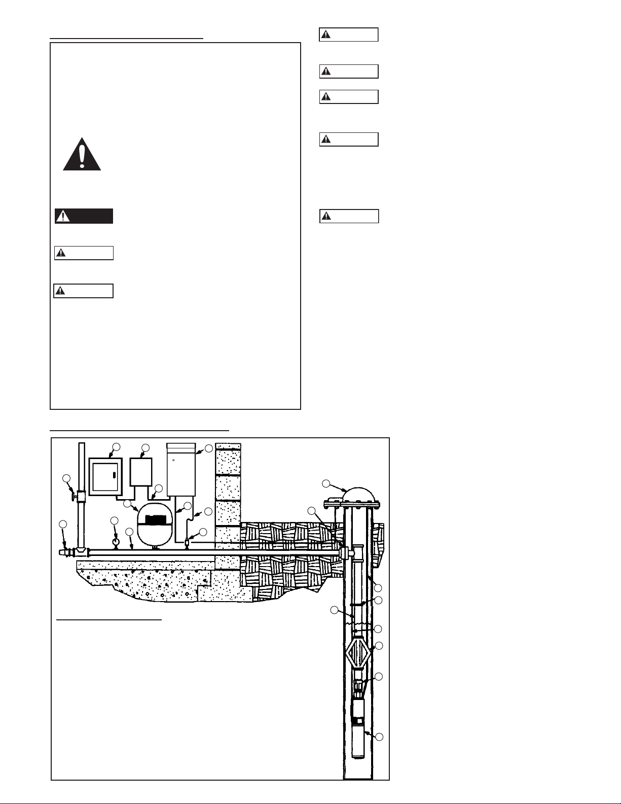
TYPICAL INSTALLATION
TYPICAL INSTALLATION
This controller is not designed for use
around swimming pools, open bodies of
water, hazardous liquids, or where flammable gases exist.
Do not use GFCI input power. This will
cause nuisance faults.
Disconnect and lockout electrical power
before installing or servicing any
electrical equipment.
ELECTROCUTION HAZARD.
CONTROLLER INPUT GROUND
TERMINAL (GND) AND ALL EXPOSED METAL
PIPING, INCLUDING PRESSURE TRANSDUCER
CASE, MUST BE CONNECTED TO THE SERVICE
ENTRANCE GROUND TERMINAL.
All electrical work must be performed
by a qualified technician. Always follow
the National Electrical Code (NEC), or the Canadian
Electrical Code, as well as all local, state and provincial
codes. Code questions should be directed to your local
electrical inspector. Failure to follow electrical codes and
OSHA safety standards may result in personal injury or
equipment damage. Failure to follow manufacturer’s
installation instructions may result in electrical shock,
fire hazard, personal injury or death, damaged
equipment, unsatisfactory performance, and may void
manufacturer’s warranty.
NOTICE: Some installations pull a vacuum on the
transducer when the system is drained. The new controller
is designed to protect against up to 17” Hg. of vacuum
on the transducer. An optional Gauge Guard, order
no. 6K210, will protect the transducer from a vacuum
condition.
11
20
17
13
16
15
10
19
9
4
12
14
PARTS DESCRIPTION:
1) Pump and Motor 10) Power Supply Cable
2) Check Valve (built-in 11) Service Entrance
on some models) 12) Pressure Sensor Cable
3) Torque Arrestor (optional) with drip loop
4) Pump Power Cable 13) Diaphragm Tank
with Splice Kit 14) Pressure Transducer
5) Electrical Tape 15) Pressure Gauge
(Cable to Pipe) 16) Relief Valve
6) Safety Rope (optional) 17) Shut-Off Valve
7) Well Cap / Seal 18) Drop Pipe
8) Pitless Adapter 19) Lateral Pipe
9) Controller 20) Electrical Disconnect
7
8
6
5
18
4
3
2
1
3
Page 4

Ratings
WARNING
CAUTION
CAUTION
CAUTION
WARNING
CAUTION
Refer to serial number label on enclosure.
Required Materials
• BF Pump Controller with Transducer and Transducer Wire
• Pump (water end)
(see Speed Selector Switch for 60 Hz or 80 Hz Operation)
• Motor: 230 V, three phase (3Ø), 3450 RPM
• Pressure Relief Valve – piped to a drain for safety
• Pressure Gauge – for setting system pressure
• Heat Shrink Kit – one required for each underwater or
underground splice (mandatory)
• Tank Tee or (2) ¼" NPT Female pipe fittings for pressure
sensor and pressure gauge connections
• Pipe and fittings – as necessary per each system
• Disconnect Switch: 230 V, 2 pole, properly sized
(see Controller, Breaker, Generator Sizing Table)
• Copper Wire: Minimum 75ºC rated wire, double
jacketed is recommended but not mandatory
(see Wire Sizing table)
• Tank: diaphragm style tank
(see Tank Sizing Section and Chart)
2: INSTALLATION
2: INSTALLATION
Determine where the Controller, Pressure Tank and
Transducer will be located before starting the installation.
Controller
The controller is rated NEMA 3R (Raintight) so it may be
located outdoors. It must be mounted vertically. Locate
the enclosure in a shaded area where the temperature
stays within 0ºF to +122ºF (-18ºC to +50ºC). Since the
controller is designed for outdoor mounting it may be
located at the wellhead.
Opening Controller Cover
Lay the controller on a flat surface or hang
on wall before removing the cover screw.
Failure to do so may result in dropping and damaging the
unit. Once screw is removed, lift the cover up and out to
remove. There is a locking tab on the bottom of the unit to
accommodate a padlock if so desired.
Mounting Controller
Three screws are provided for mounting the enclosure.
Using the enclosure as a guide, select a mounting location.
First install the top screw in the mounting surface leaving
the head of the screw approximately 1⁄8" from the surface.
Hang the enclosure on this screw. Finish by installing the
two bottom screws and tightening the top screw. Be sure
to leave a minimum of 6" of clearance on each side of the
controller to ensure proper cooling.
EXPLODING TANK CAN INJURE OR
KILL.
Always protect the tank from over pressure by installing
a pressure relief valve large enough to limit the system
pressure below the maximum working pressure of the tank.
Install the tank at a point in the system where the maximum
possible system pressure cannot exceed the maximum
working pressure of the tank. Install the pressure relief valve
at the tank.
Avoid property damage caused by pressure
relief valve opening. Pipe the pressure relief
valve discharge to a drain or other location so that property
damage and flooding will not occur.
Locate the tank and transducer where they
will not freeze.
Ensure the system pressure setting does not exceed the
maximum working pressure of the tank.
For optimum performance, as a minimum, we recommend
using the same size pipe as the pump discharge between the
pump and the tank. Smaller diameter pipe may severely limit
the maximum capacity of the system. On long runs, larger
pipe may be beneficial for optimum performance and flow.
If using a torque arrestor, install it on the
discharge pipe before connecting pipe to
the discharge head.
Diaphragm Tank Sizing and Pre-Set Pressure
Recommendations:
Diaphragm type (captive air) tanks are required on these
systems.
Table 1: Tank Sizing Selection
Maximum
Pump GPM
10 2 V6P TP6P
23 4.5 V15P TP15P
41 8.2 V25P TP25P
70 13.9 V45 TP45
100 19.9 V60 TP60
Use Total Tank Volume, not drawdown volume, to select
the proper tank size. The total tank volume should be
approximately 20% of the pump’s maximum flow. For
example, when using a 10 gpm pump the system requires a
2 gallon (total volume) tank.
The tank sizing recommendations are field proven to
prevent objectionable pressure drops on start-up and
provide smooth operation for the majority of variable speed
pump systems.
Recommended Tanks
Total Volume Order No. or Order No.
For a 5 PSI Pressure Drop Set-up:
Set the tank pressure, while tank is empty of water, to 20 psi
below the desired system pressure setting. Ex. for a 50 psi
system pressure, charge the tank to 30 psi.
Pump and Piping
Do not install any valves, flow control
devices or filters between the pressure
transducer and the pump. It is allowable to run branches
off the pipe between the pump and transducer as long
as no flow restricting devices are between the pump and
transducer.
NOTICE: The terms Transducer and Pressure Sensor are
equal and interchangeable.
4
For a 20 PSI Pressure Drop Set-up:
Start with the tank pre-charge set 30 psi below the set
point, this setting may need minor adjustment for optimum
performance as all systems and piping are slightly different.
Splicing Drop Cable To Motor Leads
The underwater connection where the drop cable connects
to the motor wires must be done using a waterproof heat
shrink kit. To make the connection, first strip the wires
½" and place the heat shrink tubes over the wires. Then,
Page 5
CAUTION
connect the wires using the crimps. Finish by shrinking the
CAUTION
CAUTION
WARNING
CAUTION
tubes over the crimps heating from the center outward.
The sealant in the tube will flow out the ends making a
watertight seal. If a heat shrink tube is burnt or split, the
connection will need to be remade.
Vinyl electrical tape is not acceptable for
underwater splices when using variable
speed drives due to the high potential for leakage to ground
through taped joints. Failure to use a waterproof heat shrink
kit will void the warranty.
Before installing the motor in the well, the drop cable must be
connected to the motor wires. Refer to the wire size chart when
selecting wire size for the drop cable. See Wire Sizing Table.
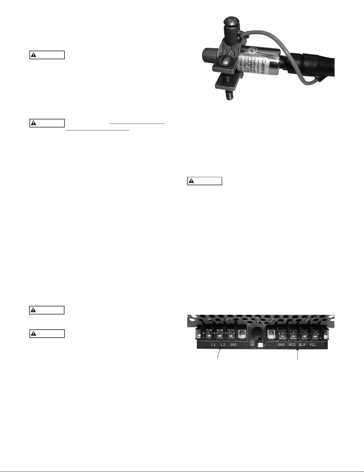
Figure 1: Transducer Grounding
Wiring Pressure Transducer
Transducer wires must never be in same
conduit with power wires. There should
always be a minimum of 12" between transducer wires
and power wires. Failure to separate these wires can cause
controller malfunctions.
The pressure transducer cable is pre-wired at the factory. If
desired, the length of the cable can be changed. The cable
can also be put in conduit to protect against damage.
To change the length of the transducer cable:
• Cable length cannot exceed 200'.
• Disconnect transducer wires from terminal block by pushing
down on tabs at rear of block one at a time and pulling the
wires out of the terminal.
• Splice additional cable to transducer wire, cut off excess as
required.
• Reconnect wires to terminal block. Be sure wire colors match
labels on circuit board (B = Black, R = Red, W = White).
To put the transducer cable in conduit, do the following:
Disconnect the cable from the terminal block and remove
the cable strain relief in the bottom of the enclosure.
Starting at the enclosure, run flexible or rigid ½" conduit to
where the transducer is located. The last few feet of conduit
adjacent to the transducer will need to be flexible. The
conduit must be well supported – NO stress can be placed
on the pressure transducer connector. Use a strain relief
bushing to seal around the pressure transducer connector.
After reconnecting the transducer wires to
the terminal block and ground terminal, tug
on each wire individually to ensure they are tight.
Any exposed metal in the system piping,
including transducer case, must be grounded
to the service entrance per NFPA 70: National Electrical
Code, Article 250.
The transducer cable has a Green ground wire and a ground
clamp supplied to facilitate grounding the transducer. See
Figure 1.
Motor Wires – See Table 4
NOTE: A MINIMUM OF 75ºC COPPER WIRE IS MANDATORY.
Refer to the Table 4 for wire sizing and maximum wire
lengths. Charts are designed to limit voltage drop to 5%.
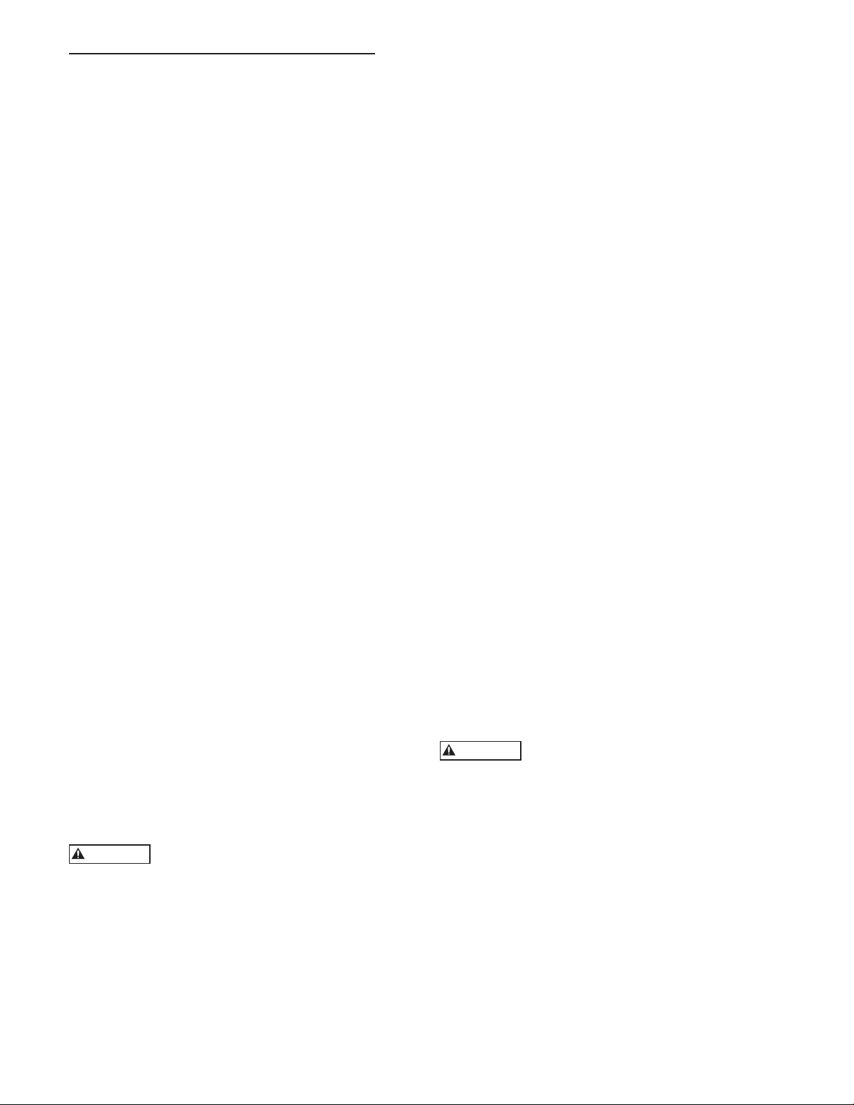
Figure 2 shows the terminal block where the motor and
input wires connect. The protective cover on the terminal
block snaps off and on. Attach the motor wires to the
terminals according to colors marked on circuit board:
GND = Green, RED = Red, BLK = Black, YEL = Yellow.
Reversing any two leads on RED/BLK/YEL will change the
direction of motor rotation. Later during start-up you may
need to change motor rotation.
Input Power
SHOCK OR ELECTROCUTION
HAZARD
Connect a ground wire from the service panel to the
terminal marked GND. Controller has high leakage to
ground. Controller ground terminal must be connected to
the service entrance ground terminal. Failure to do so will
result in high voltage being present on the controller chassis.
Connect two “hot” wires from the 2 pole circuit breaker to
the terminals marked L1 and L2.
The input power system used must be a grounded power
system. The voltage measured from L1 to L2 must be in the
range of 196Vac to 265Vac. The voltage measured from
L1 to GND must be equal to the voltage measured from
L2 to GND. These voltages must be within the range of
120Vac +/- 10%. Reduced input voltage will reduce system
performance.
Do not use a Ground Fault Circuit Interruptor (GFCI) with
this product or nuisance tripping will result.
Incoming Power
Figure 2: Wiring Connections
NOTE: IT MAY BE NECESSARY TO PLACE A DISCONNECT SWITCH IN FRONT OF AND WITHIN SIGHT
OF THE CONTROLLER – CONSULT LOCAL CODES.
Wires to Motor
Size wire for worst case scenarios (low voltage) and stay
within the charts recommendations. Insure that the wire is
rated for direct burial and/or submergence.
5
Page 6
3. INSTALLER PRE-START SELECTIONS
WARNING
WARNING
3: INSTALLER PRE-START SELECTIONS
DRIVE SETTINGS AND PROTECTION
Maximum Frequency (Speed) Switch
The Maximum Frequency switch sets the maximum
frequency (motor speed) the controller uses to energize the
motor to either 60 or 80 Hz.
• 60 Hz - Use for matched pump-motor combinations
where the motor HP and pump HP are the same.
Example: 2 HP WE and 2 HP Motor
• 80 Hz - Use for mis-matched pump-motor combinations
where motor HP is larger than the pump HP (typically 2x
larger).
Example: 1 HP WE and 2 HP Motor
• The unit is factory pre-set at 60 Hz.
Dry Well Sensitivity
Selections are High or Low. This function protects the
system from running dry. The selection depends on
several conditions and pump size.
Start with the sensitivity on high and test by running
pump at various flows. If a dry well fault is triggered,
switch to low setting. The unit is factory pre-set at high.
Restart times in minutes are: 1, 10, 20, 30, 60, 60 and
repeating every 60 minutes thereafter.
Example: 1st fault shuts down for 1 minute, next fault
shuts down for 10 minutes, then 20, etc.
• See Table 3 or the motor nameplate for Motor Amperage
ratings. The controller limits the output current to the
value selected by this dial. It does this by lowering the
frequency and voltage. If the current does not come
within the selected value by the time the frequency is at
40Hz, the controller will shut down and indicate Bound
Pump error (4 red blinks).
PRESSURE ADJUSTMENT
Pressure Adjustment Pushbuttons
The INCREASE and DECREASE pushbuttons are used
to set the desired pressure. To adjust pressure, press and
hold (do not tap) the button until the desired pressure is
obtained. It may take a full minute to adjust the pressure
from maximum to minimum, please be patient. Pressure can
only be changed when the pump-motor is running.
Controller Status Indicator (Light Visible Through
Window in Cover)
The controller status indicator light has 3 possible modes:
• Solid green = Standby, pump not running. There is no
water flow or the SWITCH INPUT is open.
• Blinking green = Pump running. There is flow (possibly a
leak) and the SWITCH INPUT terminals are connected to
each other (closed).
• Red = Error/Fault. Light will blink to indicate a particular
fault. See Troubleshooting Section for Fault Codes.
Broken Pipe Protection
ON Position - Used for constant pressure systems. The
drive will turn off if the system pressure drops 20 PSI
below the system set point pressure for a minimum of
30 seconds. This fault must be manually reset, it will not
clear automatically, this may prevent property damage if
a pipe breaks.
OFF Position - Use for open discharge situations such as
flushing a tank, filling a pond or tank, or whenever the
system pressure will be 20 psi or more below the system
set point pressure.
Pressure Drop – 5 PSI or 20 PSI
The pressure drop before the pump restarts can be set to
the standard 5 PSI or to 20 PSI.
The 20 PSI setting results in fewer starts for systems with
leaks. It is recommended for irrigation systems. It will
require a tank pre-charge adjustment. See Tank Sizing.
CURRENT LIMIT PROTECTION
Motor Overload Setting Dial
Failure to properly adjust the Motor
Overload Setting before applying power may
damage the motor or wire and void the warranty.
• Use Table 2 to determine which controller and setting to
use. Note that some 200V motors require upsizing to the
next larger controller.
• Set the Motor Overload - Turn the dial pointer to align
with the motor’s service factor amps (SFA) as listed on
the Motor Overload / Current Limit chart. Choose the
amperage value from the Current Limit Settings chart
on UIB that is closest to the SFA listed on the motor
nameplate but not higher.
Purging System
Open a valve and turn power on to the controller. If
the system pressure is below the factory preset pressure
setting (50 psi), the status light will begin blinking green
indicating that pump is running. The controller hums
when it is running. This is normal.
It is common for the pump to be air bound at
first, especially with shallow wells. In this case, the
controller will begin testing for a dry well (refer to the
troubleshooting section for a description of Dry Well
Detection).
Once the water is flowing, be sure to open all valves to
purge air from the system.
Checking Rotation
It is possible that the motor is rotating in
the wrong direction. The pump will work
but will have greatly reduced performance if rotating
backwards.
To check rotation, perform the following test:
Connect an amp probe to one of the power supply
wires. Run the system with several valves open and note
the pressure and amps. Leave the valves open, turn the
power off, and wait 5 minutes for the hazardous voltages
to discharge.
Swap red and black motor leads where they connect to
the controller terminal block (NOT L1 and L2).
Turn power back on and let the system pressure
stabilize. Again note the pressure and amps. Whichever
wire position provided the most pressure/flow is the
correct wire position. If there was little difference in the
pressure/flow, then whichever had the lower amp reading
is the correct wire position.
Turn the power off, wait 5 minutes and swap the wires
back if necessary.
6
Page 7

Replace the plastic protective covers on the terminal
DANGER
DANGER
block.
Checking for leaks
Constant pressure systems utilizing small tanks run
whenever there is demand. Even small leaks can prevent
a pump from turning off. To check for leaks, close all
valves, turn power off to the controller, and note the
pressure displayed on the pressure gauge. Tap the gauge
to ensure you get an accurate reading.
Wait ten minutes and check the gauge again tapping to
prevent the needle from sticking. If the pressure dropped
then the system may have a leak*.
*If a system is pressurized after having been unpressurized, it will continue to expand for several
minutes. This expansion causes the pressure to drop
and can be misinterpreted as a leak. Allow a system to
stabilize for 10 minutes under pressure before
performing the aforementioned leak test.
A spring check valve placed on the pump side of the
tank and transducer will often improve the ability of the
system to shut down.
SWITCH INPUT
Optional Switch Input and Switch Input
Status Light
Log onto www.centripro.com, click on Goulds Pumps or
Red Jacket, click on Electrical Controls Water, click on
Balanced Flow for more detailed examples on using the
Switch Input.
Electrocution Hazard. Opening SWITCH
INPUT does not de-energize controller
or any of its outputs. Always treat wire terminals of this
controller as energized until power supply to the controller
has been removed for 5 minutes.
SWITCH INPUT - for connection of an external switch
or control device used to start and stop the pump. Devices
such as an over-pressure switch, level (float) switch or any
other non-powered switch (time delay, flow, etc.) can be
connected to this input.
The Switch Input terminals have a Jumper Wire installed at
the factory (do not confuse the jumper wire on the Switch
Input with the Transducer Jumper next to the Transducer
Connection Terminals, see Transducer Jumper below).
The Switch Input terminals must be connected (closed) for
the pump to operate. If they are not connected the Switch
Input Status Light (visible inside the enclosure) will be Solid
RED and the Controller Status Light will be Solid GREEN
indicating that the pump-motor is off. Remove the Jumper
Wire when connecting a float or over-pressure switch:
CONSTANT PRESSURE SYSTEM - with an Over-Pressure
Switch:
• Connect two wires from the Load and Lead connections
of a pressure switch to provide over-pressure protection.
In the event the pressure transducer fails, this will prevent
high pressure from damaging piping.
• The over-pressure switch cut-out setting must be a mini-
mum of 10 PSI higher than the system set point pressure.
• Set the over-pressure switch cut-out 5 - 10 PSI lower than
the pressure relief valve (PRV) pop-off pressure. This will
turn the system off before the pressure relief valve opens.
• Ex. On a system with a 50 PSI set point, set the over-pressure switch cut-out at 60 PSI with a typical PRV setting of
75 PSI. In the event the transducer fails at high pressure
the switch will turn the system off before the PRV pops.
• Typical UIB Settings For This Type System:
• 60 or 80 Hertz (depends on pump/motor)
• Dry Well - High (switch to low if it trips while pumping
water)
• Broken Pipe - On
• Pressure Drop - 5 PSI
• Transducer - Connected
• Transducer Jumper - Bottom Position (Factory Setting)
• Pressure Switch Connected to Switch Input
FLOAT SWITCH OPERATION - Filling a Pond or Tank
(Non-Constant Pressure System):
• Connect two wires from a float (level) switch to fill or
empty a tank, pond, etc. The pump will run when the
level switch contacts close. The maximum switch wire
length tested is 200’. The pump will run at maximum
speed when the float switch is closed.
• Typical UIB Settings For This Type System:
• 60 or 80 Hertz (depends on pump/motor)
• Dry Well - High (switch to low if it trips while pumping
water)
• Broken Pipe - Off
• Pressure Drop - 5 or 20 PSI
• Transducer - Not Connected
• Transducer Jumper - Top Position (Installer Must Move)
• Float Switch Connected to Switch Input
FLOAT SWITCH OPERATION - Filling a Pond or Tank
and Constant Pressure System:
• Connect two wires from a float (level) switch to fill or
empty a tank or pond and a pressurized system. The
maximum switch wire length tested is 200’. The pump
will operate at various speeds and try to maintain the set
point pressure. If piping is large and it cannot maintain
set point pressure it will operate at maximum speed.
• Typical UIB Settings:
• 60 or 80 Hertz (depends on pump/motor)
• Dry Well - High (switch to low if it trips while pumping)
• Broken Pipe - On (switch to off if pressure drops by 20
PSI or more)
• Pressure Drop - 5 PSI
• Transducer - Connected
• Transducer Jumper - Bottom Position (Factory Setting)
• Float Switch Connected to Switch Input
Transducer Jumper
Explosion Hazard. Keep jumper in bottom
position whenever a pressure transducer is
used. Failure to do so may cause a pressure transducer error
to be ignored and an over-pressure hazard to result.
For applications not requiring a pressure transducer such
as level control, the transducer can be removed. When
the transducer is not used, the Transducer Jumper must be
placed in the top position to prevent a sensor error. Never
place the jumper in the top position when using a pressure
transducer.
7
Page 8
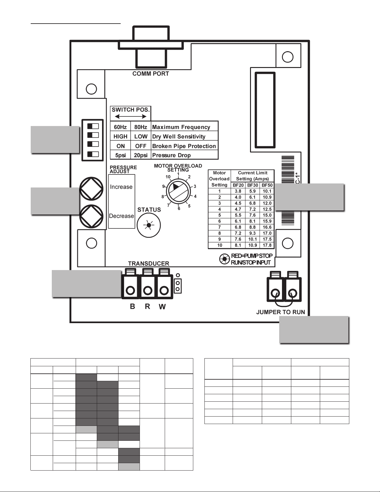
USER INTERFACE BOARD
USER INTERFACE BOARD
Drive
Settings /
Protection
Pressure
Adjustment
Current Limit Dial
(Motor Overload
Protection)
Pressure
Transducer
Connection
TRANSDUCER
JUMPER
Switch Input (Over
Figure 3: UIB (User Interface Board)
Pressure Protec-
tion, Level Control)
Table 2: Controller, Breaker, Generator Sizing Table 3: Service Factor Amps 3 Phase Motors
3 Phase Motor Controller Model ② Circuit Generator ④
HP Voltage ① BF20 BF30 BF50 Breaker ③ (VA)
¾ 230
200
1 230
200
230
1½
200
2 230
200
230
3
40
5 230
200
8100
200
15
20
30
50
2900
3500
4400
6100
13300
8
230 Volt, 3Ø 200 Volt, 3Ø
HP
CentriPro Franklin CentriPro Franklin
SFA SFA SFA SFA
¾ 4.0 3.8 4.5 4.4
1 4.7 4.7 5.5 5.4
1½ 6.1 5.9 7.2 6.8
2 7.6 8.1 8.8 9.3
3 10.1 10.9 12 12.5
5 17.5 17.8 20.2 20.5
NOTES:
① Motor Nameplate must be the same as supply voltage.
② Shaded areas indicate which controller models can be used with which
motors. Lighter shading indicates combinations where controller will limit
peak performance to 85% of catalog value for pump/motor.
③ Circuit Breaker or Dual Element Time Delay Fuse Size (Amps) protecting
branch circuit supplying controller.
④ Minimum size of single phase 240 V generator required.
Page 9

Table 4: Wire Sizing
Maximum Cable Lengths in Feet to Limit Voltage Drop to 5% for 230 V Systems ①
Service Entrance to Controller
Controller Motor
Input
½ 366 583 925 1336 2107 3345 4175 5267 6637 8364
¾ 279 445 706 1020 1608 2552 3186 4019 5065 6383 8055
1 226 360 571 824 1300 2064 2576 3250 4095 5161 6513 8201
230V
1½ * 286 455 657 1036 1644 2052 2589 3262 4111 5188 6533 8236 9710
1 PH
2 * * 331 478 754 1197 1495 1886 2376 2995 3779 4759 5999 7073 8455 9852
3 * * 246 355 561 890 1111 1401 1766 2225 2808 3536 4458 5256 6283 7321 8343
5 * * * 218 343 545 680 858 1081 1363 1720 2165 2730 3219 3847 4483 5109 6348
Controller to Motor
Controller Motor
Input
½ 905 1442 2290 3306 5213 8276
¾ 690 1100 1748 2523 3978 6316 7884 9945
1 558 890 1413 2040 3216 5106 6375 8041
230V
1½ 445 709 1126 1625 2562 4068 5078 6406 8072
3 PH
2 324 516 820 1184 1866 2963 3699 4666 5879 7410 9351
3 241 384 609 880 1387 2202 2749 3467 4369 5506 6949 8750
5 * 235 373 539 849 1348 1683 2123 2675 3372 4255 5358 6755 7964 9520
① Reduce lengths by 13% for 200 V systems. * Wire does not meet the N.E.C. ampacity requirement.
② Lengths in bold require 90º C wire. Shading indicates 40º C maximum ambient.
Copper Wire Size 75ºC Insulation Exposed to a Maximum of 50ºC (122ºF) Ambient Temperature ②
HP
14 12 10 8 6 4 3 2 1 1/0 2/0 3/0 4/0 250 300 350 400 500
Copper Wire Size 75ºC Insulation Exposed to a Maximum of 50ºC (122ºF) Ambient Temperature ②
HP
14 12 10 8 6 4 3 2 1 1/0 2/0 3/0 4/0 250 300 350 400 500
The lengths in each of the Wire Sizing tables represent 100% of the allowable voltage drop when motor is
running at full load. When sizing wire, the voltage drop of each wire segment must be included. The total
must not exceed 100% of the allowable drop. Take for example a 1.5 HP motor with a distance from Service
Entrance to Controller of 100' and 500' between the Controller and Motor.
• Service Entrance to Controller = 100' of 10 AWG (100/455) = 22 % (455' is from the S.E. to
Controller chart)
• Controller to Motor = 500' of 12 AWG (500/709) = 71 % (709' is from the Controller to
Motor chart)
Total Drop (must be ≤ 100%) 93 %
If the distance from the Controller to Motor was 600' (600/709) = 85% + 22% = 107%, we would need to
use #10 wire for that segment, ex. 600/1126 = 53% + 22% (for 100' of #10) = 75% which is acceptable.
It is also acceptable to use different wire sizes for the Buried and Well sections of wire.
Table 5: Possible Combinations for TRANSDUCER, JUMPER AND SWITCH INPUT
Scenario
Transducer Position Input Status Indicator Indicator
Bottom Open Disabled Solid Green Solid Red
Constant
pressure operation
else solid green
Level or pressure
switch control
* See description of Maximum Speed Switch and Motor Overload Setting Switch for their effect on Full Speed value.
Pressure Jumper Switch Controller Status Switch Status
Connected
Top Open Disabled Solid Green Solid Red
Not
Connected
Bottom Closed Constant pressure
Top Closed Run Full Speed* Blinking green Off
Blinking green if flow
Off
9
Page 10

4: TROUBLESHOOTING
4: TROUBLESHOOTING
The status light described in Section 3 Installer Pre-Start Selections is used to indicate system status i.e. running,
stopped, or faulted. When faulted, the status light will be red. The error code is the number of quick flashes followed
by a 1 second pause. The number of flashes can be any number from 2 to 8. The error code will be repeated until
cleared. Some errors will clear themselves with time. Others must be cleared manually by turning the power off for 1
minute. The following table describes the various errors that can occur.
NO LIGHT
Flashes Controller Status Description
None Low/No Input Voltage Check the input voltage to the controller. Measure the voltage between
L1 and L2 using an AC Voltmeter. This voltage should be greater
than 190Vac.
GREEN LIGHT CODES
Flashes Controller Status Description
Constant Standby/Low Voltage Constant Green Light indicates the pump is off. The system is in Standby
mode when there is no flow in the system and the pressure setting has been
reached. The system is in a Low Voltage condition when the line input
voltage drops below 190VAC.
Blinking Pump Running Flashing Green Light indicates the pump is running.
RED LIGHT CODES
Flashes
This information is to be used by professional installers or qualified
Constant Controller Error Internal controller fault. Replace controller.
2 Blinks Dry Well This fault can be caused by:
• Water supply level in well falls below suction inlet of pump.
• Plugged suction screen.
• Restriction in pipe between pump and pressure sensor.
• Air bound pump – see “Purging System”
• Incorrect setting of “MAXIMUM SPEED” switch. Be sure to set the
“MAXIMUM SPEED” switch to 80 Hz when using mismatched pumps
(water ends) and motors.
• Incorrect setting of “MOTOR OVERLOAD SETTING (SFA)” switch.
Ensure the Motor Overload Setting (SFA) Switch is not set higher than the
Service Factor Amps (SFA) listed on the motor nameplate.
In systems where the motor operates at less than Service Factor Amps the
controller may show a false “dry well” fault. See Dry Well Sensitivity Section.
If problems persists, please verify supply capacity.
The controller will automatically restart according to the chart below.
Dry Well Fault Reset table:
Fault 1 (Start Point) - resets after 1 minute
Fault 2 - resets after 10 minutes
Fault 3 - resets after 20 minutes
Fault 4 - resets after 30 minutes
Fault 5 - resets after 60 minutes
Will repeat every 60 minutes, when the system cycles Off the
Dry Well will default back to the start point.
Controller Status
Controller Action
To clear the fault, turn off
power to the controller, wait
1 minute, turn on power to
the controller. If fault persists
contact installer.
The controller will
automatically restart according
to the table shown on the right.
If fault persists contact installer.
Fault Description
personnel only.
Table 6: Fault Blink Codes (continued on next page)
10
Page 11

WARNING
RED LIGHT CODES
Flashes Controller Status Description
3 Blinks Sensor Fault This fault can be caused by:
• Disconnected sensor. Disconnect sensor from sensor cable connector and
The controller will not run
if the signal from the
sensor is disconnected or out
of tolerance. The controller
will automatically restart when
the signal is within tolerance. If
fault persists contact installer.
reconnect to ensure a good connection.
• Disconnected sensor cable lead inside the controller. Check for loose wires
where the sensor cable connects to the circuit board by tugging on each wire.
• Broken wire in the sensor cable.
• Miswired sensor cable. Check that the wires are connected to the correct terminals on the sensor connector. The correct location of the wires is indicated
on the circuit board. B=Black, R=Red, W=White.
• Failed sensor. With the sensor cable connected to the circuit board, measure
the DC voltage between the black and white wires of the sensor cable at
the sensor connector. The voltage measured should be between 0.5Vdc and
4.5Vdc depending on the system pressure, see chart below.
• A vacuum on the sensor (transducer) of 17" Hg or more will cause a sensor
fault, eliminate the vacuum.
5
4.5
4
3.5
3
2.5
2
1.5
Transducer Output (Volts DC)
1
0.5
0
0 25 50 75 100 125 150 175 200
Sensor Output vs. Applied Pressure
Pressure (PSI)
100 PSI Sensor
200 PSI Sensor
4 Blinks Pump or Motor Bound This fault can be caused by:
• Installing a 1Ø motor - system requires a 3Ø, 200 or 230 V motor.
• Mechanical binding from debris in pump.
• Electrical failure of the motor.
• Incorrect setting of “MOTOR OVERLOAD SETTING (SFA)” switch.
A false “bound pump” error will be displayed if the switch is set too low.
Verify the error by turning power to controller off for 1 minute and then on.
The controller will try to restart the
motor three times before displaying
this fault. To clear the fault, turn off
power to the controller, wait 1 minute, turn on power to the controller.
If fault persists contact installer.
Pump/Motor must be checked if fault persists.
5 Blinks Short Circuit This fault can be caused by:
• Electrical failure of the motor.
• Electrical failure of wiring between controller and motor.
Verify the error by turning power to controller off for 1 minute and then on.
If error persists, motor and wiring between controller and motor must be
checked. Turn power off for 5 minutes. Remove the three motor wires from
the terminal block. Check wiring and motor for shorting phase to phase and
phase to ground. Refer to motor’s manual for information on resistance
readings.
If this fault is detected while
the pump is running, the
controller will attempt to restart
three times before displaying this
fault. To clear the fault, turn off
power to the controller, wait 1 minute, turn on power to the controller.
If fault persists contact installer.
6 Blinks Ground Fault This device does not provide personnel protection against
shock. This function is intended for equipment protection
only.
This fault can be caused by:
• Electrical failure of the motor
• Electrical failure of wiring between controller and motor.
• Miswiring of motor cable.
The controller will not restart
if displaying this fault. To clear
the fault, turn off power to the
controller, wait 1 minute, turn
on power to the controller. If
fault persists contact installer.
Verify the error by turning power to controller off for 1 minute and then on.
If error persists, motor and wiring between controller and motor must be
checked. Turn power off and wait 5 minutes. Remove the three motor wires
and ground wire from the terminal block. Check wiring and motor for
shorting phase to ground using a megohmmeter (“megger”). A reading less
than 200K Ohms indicates faulty insulation in the motor cable or motor.
Test each to determine fault location.
Table 6: Fault Blink Codes (continued on next page)
11
Page 12

ITT
CentriPro
Flashes Controller Status Description
7 Blinks Temperature This fault can be caused by:
• High ambient temperature. The maximum ambient temperature
rating is 122º F (50º C).
• Low ambient temperature. The minimum ambient temperature
rating is -4º F (-20º C).
Check for a fan failure. The fan will turn on when the temperature
inside the controller reaches 140º F (60º C). The fan will turn on for
1 second each time the controller starts the motor. If the fan never
turns on, check fan connections and replace as needed. Ensure that
the external fan intake filter is not blocked or clogged. It can be
removed for cleaning and replacements are available.
8 Blinks Open Lead This fault can be caused by:
• Disconnected or broken wire between the controller and motor.
Verify the error by turning power to controller off for 1 minute and
then on. If error persists, motor and wiring between controller and
motor must be checked. Turn power off for 5 minutes. Remove the
three motor wires from the terminal block. Using an ohmmeter,
measure the resistance from phase to phase. A disconnected or
broken wire will be indicated by a high resistance reading (20 ohms
or higher).
9 Blinks Broken Pipe This fault can be caused by:
• Pressure 20 PSI below set point for 30 seconds. May be a broken
pipe or tripped pressure relief valve. If 20 PSI or more pressure
drop for 30 seconds is normal for the system, switch the broken
pipe protection off or change system to prevent the pressure drop.
The controller will auto-
matically restart when the
temperature reaches an
acceptable level. If fault
persists contact installer.
The controller will not
restart if displaying this
fault. To clear the fault, turn
off power to the controller,
wait 1 minute, turn on pow-
er to the controller. If fault
persists contact installer.
The controller will not
restart if displaying this
fault. To clear the fault, turn
off power to the controller,
wait 1 minute, turn on pow-
er to the controller. If fault
persists contact installer.
Table 6: Fault Blink Codes (continued from previous page)
Residential & Commercial Water Systems
RED LIGHT CODES
This warranty applies to the Balanced Flow Series Controller manufactured by CentriPro.
Any part or parts found to be defective within the warranty period shall be replaced at no charge to the dealer during the warranty period. The warranty pe-
riod shall exist for a period of twenty-four (24) months from date of installation or thirty (30) months from date of manufacture, whichever period is shorter.
A dealer who believes that a warranty claim exists must contact the authorized CentriPro distributor from whom the equipment was purchased and furnish
complete details regarding the claim. The distributor is authorized to adjust any warranty claims utilizing the CentriPro Customer Service Department.
The warranty excludes:
(a) Labor, transportation and related costs incurred by the dealer; (d) Consequential damages of any kind; and,
(b) Reinstallation costs of repaired equipment; (e) Reimbursement for loss caused by interruption of service.
(c) Reinstallation costs of replacement equipment;
For purposes of this warranty, the following terms have these definitions:
(1) “Distributor” means any individual, partnership, corporation, association, or other legal relationship that stands between CentriPro and the dealer in
purchases, consignments or contracts for sale of the subject equipment.
(2) “Dealer” means any individual, partnership, corporation, association, or other legal relationship which engages in the business of selling or leasing equip-
ment to customers.
(3) “Customer” means any entity who buys or leases the subject equipment from a dealer. The “customer” may mean an individual, partnership, corporation,
limited liability company, association or other legal entity which may engage in any type of business.
CentriPro and the ITT Engineered Blocks Symbol are
registered trademarks and tradenames of ITT Corporation.
SPECIFICATIONS ARE SUBJECT TO CHANGE WITHOUT NOTICE.
CENTRIPRO LIMITED WARRANTY
THIS WARRANTY EXTENDS TO THE DEALER ONLY.
®
IM182 Revision 12 February, 2010
Copyright (c) 2010 ITT Corporation
Engineered for life
Page 13

ITT
CentriPro
Sistemas de Residential y Commercial Water
CentriPro
BALANCED FLOW® CONTROLADOR DE
BOMBA SUMERGIBLE
Manual de instalación, operación y localización de fallas
CentriPro es una marca de
fábrica de ITT Corporation.
www.goulds.com
Engineered for life
®
Page 14

Información del propietario
Información del propietario
Índice
Índice
Número de modelo del controlador:
Número de serie del controlador:
Número de modelo de la bomba:
Número de serie de la bomba:
Número de modelo del motor:
SFA del motor:
Número de serie del tanque:
Comerciante:
Nº telefónico del comerciante:
Fecha de instalación:
Longitud de los cables (pies)
Entrada de servicio al controlador:
Controlador al pozo:
Superficie del pozo al motor:
Voltaje de entrada:
ATENCIÓN: REGISTRE EL NÚMERO DE LOS MOD-
ELOS Y LOS NÚMEROS DE SERIE DE
LA BOMBA Y EL CONTROLADOR DE
ESTE MANUAL DE INSTRUCCIONES
PARA REFERENCIAS FUTURAS.
DÉSELO AL PROPIETARIO O FÍJELO
AL CONTROLADOR CUANDO HAYA
CONCLUIDO LA INSTALCIÓN.
TEMA PÁGINA
1. Instrucciones de seguridad .........................................15
Generalidades .........................................................15
Instalación típica .......................................................15
Potencia de servicio ...................................................16
Materiales necesarios ................................................16
2. Instalación ...............................................................16
Controlador .............................................................16
Montaje del controlador ............................................16
Bomba y tubería .......................................................16
Empalme del cable de bajada con los conductores
del motor ............................................................17
Cableado del transductor de presión .......................17
Cables del motor ...................................................... 17
Corriente de entrada ...............................................17
3. Selecciones de prearranque del instalador ...............18
Configuración y protección del motor.....................18
Protección con límite actual ....................................18
Ajuste de presión ....................................................18
Entrada del interruptor ........................................... 19
Placa de interfaz del usuario ....................................21
4. Resolución de problemas ...................................23-25
Garantía limitada .........................................................26
Los terminales de agua y los motores CentriPro incluyen estas etiquetas de datos adicionales. Colóquelas en la cubierta
interna del Controlador de flujo equilibrado para una futura identificación de la bomba y el motor.
®
Bomba sumergible
33GS15
www.goulds.com
CentriPro
Motor: M30432/300C313
3,00 HP
FLA: 9,2 SFA: 10,1 LRA: 59
SF: 1,15 Hz: 60
Voltios: 230 PH: 3
LE PEDIMOS QUE USE EL MANUAL DE INSTALACIÓN, OPERACIÓN Y RESOLUCIÓN DE PROBLEMAS
(IOM) DE ESTE CONTROLADOR JUNTO CON EL IOM DE LA BOMBA. EL IOM DEL CONTROLADOR
ABARCA LA INSTALACIÓN ELÉCTRICA DEL CONTROLADOR Y CUALQUIER PROCEDIMIENTO
ESPECIAL DE INSTALACIÓN REQUERIDO CON CONTROLADORES DE VELOCIDAD VARIABLE.
ITT NO SERÁ RESPONSABLE DE NINGÚN DAÑO PRODUCIDO EN UNA INSTALACIÓN DONDE SE
PERMITA QUE LA VÁLVULA DE ALIVIO DE PRESIÓN SE DESCARGUE EN UN ESPACIO HABITABLE
TERMINADO O SE DAÑE DE ALGÚN OTRO MODO LA PROPIEDAD DE UN CLIENTE. LOS DISPOSITIVOS DE SEGURIDAD DE PLOMERÍA COMO VÁLVULAS DE ALIVIO DE PRESIÓN A UN DRENAJE APROPIADO SON RESPONSABILIDAD DEL INSTALADOR Y ESTÁN FUERA DE NUESTRO CONTROL.
14
Page 15

ADVERTENCIA
ADVERTENCIA
PELIGRO
ADVERTENCIA
CUIDADO
ADVERTENCIA
ADVERTENCIA
1: INSTRUCCIONES DE SEGUIRDAD
ADVERTENCIA
1: INSTRUCCIONES DE SEGURIDAD
PARA EVITAR LESIONES PERSONALES GRAVES O
FATALES O DAÑOS SIGNIFICATIVOS A LA PROPIEDAD,
LEA Y RESPETE TODAS LAS INSTRUCCIONES DE
SEGURIDAD EN EL MANUAL Y EN EL EQUIPO.
LA FINALIDAD DE ESTE MANUAL ES AYUDAR EN LA
INSTALACIÓN Y OPERACIÓN DE ESTA UNIDAD Y SE
DEBE GUARDAR EL MISMO CON LA UNIDAD.
Este es un SÍMBOLO DE ALERTA DE
SEGURIDAD. Cuando vea este símbolo en
la bomba en el controlador o en el manual,
busque una de las siguientes palabras de
señal y esté alerta ante la posibilidad de
lesiones personales o daños materiales.
Advierte los peligros que CAUSARÁN
lesiones corporales graves, la muerte o
daños materiales importantes.
Advierte los peligros que PUEDEN causar
lesiones corporales graves, la muerte o
daños materiales importantes.
Advierte acerca de riesgos que PUEDEN
causar lesiones corporales o daños
materiales.
AVISO: INDICA QUE EXISTEN INSTRUCCIONES
ESPECIALES QUE SE DEBEN SEGUIR YA
QUE SON MUY IMPORTANTES.
EXAMINE MINUCIOSAMENTE TODAS LAS INSTRUCCIONES Y ADVERTENCIAS ANTES DE REALIZAR ALGÚN TRABAJO EN ESTE CONTROLADOR.
MANTENGA TODAS LAS CALCOMANÍAS DE
SEGURIDAD.
INSTALACIÓN TÍPICA
INSTALACIÓN TÍPICA
11
20
9
Este controlador no fue diseñado para utilizarse cerca de albercas, cuerpos abiertos de
agua, líquidos peligrosos ni donde existan gases inflamables.
No usar potencia de entrada GFCI. Esto
provocará fallas molestas.
Desconecte y bloquee la energía eléctrica
antes de instalar o realizar servicios en algún
equipo eléctrico.
PELIGRO DE ELECTROCUCIÓN. EL
TERMINAL DE CONEXIÓN A TIERRA
(GND) DE LA ENTRADA DEL CONTROLADOR Y
TODAS LAS TUBERÍAS DE METAL EXPUESTAS, LO
QUE INCLUYE LA CAJA DEL TRANSDUCTOR DE
PRESIÓN, DEBEN ESTAR CONECTADOS AL TERMINAL DE CONEXIÓN A TIERRA DE LA ENTRADA DE
SERVICIO.
Un técnico calificado debe encargarse de realizar
todos los trabajos eléctricos. Siempre cumpla
con las normas del National Electrical Code [Código oficial
estadounidense para instalaciones eléctricas] (NEC), o el Canadian Electrical Code [Código canadiense para las instalaciones
eléctricas], al igual que con todos los códigos nacionales, estatales
y provinciales. Las preguntas acerca de los códigos deberán
remitirse al inspector electricista de su zona. El incumplimiento
de los códigos de electricidad y las normas de seguridad OSHA
puede causar lesiones corporales o daños al equipo. El incumplimiento de las instrucciones de instalación establecidas por
el fabricante puede producir una descarga eléctrica, peligro de
incendio, lesiones corporales o la muerte, daños en el equipo,
desempeño deficiente y pueden anular la garantía del fabricante.
AVISO: Algunas instalaciones hacen vacío en el transductor
cuando se drena el sistema. El nuevo controlador está
diseñado para proteger contra un máximo de 17” Hg.
de vacío en el transductor. Un Protector de indicadores
opcional, no. de pedido 6K210, protege
el transductor contra el vacío.
17
13
16
15
10
4
12
19
14
7
8
DESCRIPCIÓN DE LAS PIEZAS:
1) Bomba y motor 10) Cable de suministro de energía
2) Válvula de control 11) Entrada del servicio
(incorporada en 12) Cable sensor de presión con
algunos modelos) bucle de goteo
3) Limitador de torque (opcional) 13) Tanque de diafragma
4) Cable de energía de la bomba 14) Transductor de presión
con juego de empalme 15) Manómetro
5) Cinta aislante (cable a tubería) 16) Válvula de seguridad
6) Cuerda de seguridad 17) Válvula de cierre
(opcional) 18) Tubería de descarga
7) Tapa / sello del pozo 19) Tubería lateral
8) Adaptador sin agujero
9) Controlador 20) Desconexión eléctrica
6
5
18
4
3
2
1
15
Page 16

Clasificaciones
ADVERTENCIA
ADVERTENCIA
Consulte la etiqueta con el número de serie en la caja.
Materiales requeridos
• Controlador de bomba BF con transductor y cable de
transductor
• Bomba (terminal de agua) (ver interruptor de selección de
velocidad para una operación de 60 Hz u 80 Hz)
• Motor: 230 V, trifásico (3Ø), 3450 RPM
• Válvula de alivio de presión – conectada a un drenaje por
cuestiones de seguridad
• Indicador de presión – para establecer la presión del sistema
• Kit de termocontracción – se exige uno por cada empalme
submarino o subterráneo (obligatorio)
• Conexión en T para el tanque o (2) accesorios hembra para
tubería de ¼" NPT para conexiones del sensor de presión y
el indicador de presión.
• Tubería y accesorios – según sea necesario para cada sistema
• Interruptor de desconexión: 230 V, 2 polos, de tamaño
correcto ((ver Tabla de tamaños de controlador, disyuntor y
generador)
• Cable de cobre: Como mínimo un cable certificado para
soportar hasta 75°C, se recomienda que sea de doble
camisa, pero no es obligatorio (ver Tabla de tamaños de
cables)
• Tanque: tanque de diafragma
(Ver la Sección y el Cuadro de Tamaños de tanques)
2: INSTALACIÓN
2: INSTALACIÓN
Determinar dónde estarán ubicados el Controlador, el
Tanque de presión y el Transductor antes de comenzar la
instalación.
Controlador
El controlador está clasificado como NEMA 3 R (a prueba
de lluvia), por lo que puede ser colocado en el exterior. Debe
montarse en posición vertical. Ubique la caja en un área
sombreada donde la temperatura se mantenga en un rango
de 0°F a +122°F (-18°C a +50°C). Dado que el controlador
está diseñado para ser montado en el exterior, puede estar
ubicado en la cabeza del pozo.
Cómo abrir la cubierta del controlador
PRECAUCIÓN
remover el tornillo de la cubierta. De no hacerlo, la unidad
puede caerse y dañarse. Una vez removido el tornillo, levante
la cubierta hacia arriba y hacia afuera para removerla. Hay
una pestaña de cierre en la parte inferior de la unidad para
colocar un candado si usted lo desea.
Coloque el controlador en una superficie
plana o cuélguelo de una pared antes de
Montaje del controlador
Se suministran tres tornillos para montar la caja.
Usando la caja como guía, seleccione una ubicación de
montaje. Primero instale el tornillo superior en la superficie
de montaje dejando la cabeza del tornillo a aproximadamente
1/8” de la superficie. Cuelgue la caja de este tornillo. Finalice
la tarea instalando los dos tornillos inferiores y ajustando el
tornillo superior. Asegúrese de dejar un mínimo de 6” de
espacio libre a cada lado del controlador para garantizar una
refrigeración correcta.
Bomba y tubería
No instale válvulas, dispositivos de control
de flujo o filtros entre el transductor
de presión y la bomba. Está permitido hacer correr
derivaciones de la tubería entre la bomba y el transductor
siempre y cuando no haya dispositivos de restricción de
flujo entre la bomba y el transductor.
AVISO: Los términos Transductor y Sensor de presión son
sinónimos e intercambiables.
LA EXPLOSIÓN DE UN TANQUE PUEDE
PROVOCAR LESIONES O LA MUERTE.
Siempre proteja el tanque de sobreexposición instalando
una válvula de alivio de presión que sea lo suficientemente
grande como para limitar la presión del sistema por debajo
de la presión efectiva máxima del tanque. Instale el tanque
en un punto del sistema en que la presión máxima posible
del sistema no pueda exceder la presión efectiva máxima del
tanque. Instale la válvula de alivio de presión en el tanque.
PRECAUCIÓN
Evite daños a la propiedad causados por la
abertura de la válvula de alivio de presión.
Entube la descarga de la válvula de alivio de presión a
un drenaje u otro lugar, de modo de evitar daños a la
propiedad e inundaciones.
PRECAUCIÓN
Ubique el tanque y el transductor en donde
no se puedan llegar a congelar.
Asegúrese de que la configuración de la presión del sistema
no exceda la presión efectiva máxima del tanque.
Para un desempeño óptimo, recomendamos usar como
mínimo una tubería del mismo tamaño que la descarga de
la bomba entre la bomba y el tanque. Una tubería de menor
diámetro puede limitar severamente la capacidad máxima
del sistema. En recorridos largos, una tubería de mayor
tamaño puede ser beneficiosa para un desempeño y un flujo
óptimos.
PRECAUCIÓN
Si utiliza un limitador de torque, instálelo en
la tubería de descarga antes de conectar la
tubería al cabezal de descarga.
Recomendaciones sobre el tamaño del tanque de diafragma y
la presión preestablecida:
En estos sistemas, se requieren tanques de diafragma (aire
cautivo).
Tabla 1: Selección de tamaños de tanque
GPM máximo
de la bomba
10 2 V6P TP6P
23 4.5 V15P TP15P
41 8.2 V25P TP25P
70 13.9 V45 TP45
100 19.9 V60 TP60
Use el Volumen total del tanque, no el volumen de vaciado,
para seleccionar el tamaño de tanque correcto. El volumen
total del tanque debe ser aproximadamente el 20% del
flujo máximo de la bomba. Por ejemplo, cuando se usa
una bomba de 10 gpm, el sistema requiere un tanque de 2
galones (volumen total).
Se ha verificado en el campo que las recomendaciones sobre
el tamaño del tanque previenen caídas de presión objetables
en el arranque y logran una operación libre de problemas
para la gran mayoría de los sistemas de bombas de velocidad
variable.
Tanques recomendados
Volumen total No. de pedido o No. de pedido
16
Page 17

Para una configuración con una caída de presión
ADVERTENCIA
de 5 PSI:
Configure la presión del tanque, mientras el tanque esté
vacío de agua, 20 psi por debajo de la configuración deseada
de la presión del sistema. Por Ej., para una presión de
sistema de 50 psi, cargue el tanque hasta 30 psi.
Para una configuración con una caída de presión
de 20 PSI:
Comience con la carga previa del tanque 30 psi por debajo
del punto fijado, es posible que esta configuración necesite
ajustes menores para un desempeño óptimo, ya que todos
los sistemas y las tuberías son ligeramente diferentes.
Empalme del cable de bajada con los conductores
del motor
La conexión subacuática en la que el cable de bajada se
conecta con los cables del motor se debe realizar utilizando
un kit de termocontracción a prueba de agua. Para realizar
la conexión, pele los cables ½" y coloque los tubos de
termocontracción sobre los cables. Luego, conecte los cables
usando los terminales eléctricos. Finalice colocando los
tubos de termocontracción por encima de los terminales y
calentando del centro hacia afuera. El sellador en el tubo
fluirá hacia los extremos formando un sello a prueba de agua.
Si el tubo de termocontracción se quema o se parte, será
necesario volver a realizar la conexión.
PRECAUCIÓN
motores de velocidad variable debido al alto potencial de
pérdidas a tierra a través de uniones encintadas. Si no se
utiliza un kit de termocontracción a prueba de agua, se
invalidará la garantía.
Antes de instalar el motor en el pozo, el cable de bajada debe
ser conectado a los cables del motor. Consulte el cuadro de
tamaño de cables al seleccionar el tamaño de cable para el
cable de bajada. Ver Tabla de tamaños de cables.
La cinta aisladora no es aceptable para
empalmes subacuáticos cuando se utilizan
transductor. Es necesario que los últimos pies del conducto
hasta el transductor sean flexibles. El conducto debe tener
buen soporte: NO se puede ejercer presión sobre el conector
del transductor. Utilice una boquilla del relevador de tensión
para sellar alrededor del conector del transductor de presión.
PRECAUCIÓN
y el terminal de conexión a tierra, tire de cada cable
individualmente para asegurarse de que estén bien ajustados.
PRECAUCIÓN
contar con conexión a tierra a la entrada de servicio, según
NFPA 70: Código Nacional de Electricidad, Artículo 250.
El cable del transductor viene con un cable a tierra Verde y
una abrazadera de conexión a tierra para facilitar la tarea de
conectar el transductor a tierra. Ver Figura 1.
Después de reconectar los cables del
transductor al bloque de terminales
Todo metal expuesto en las tuberías del
sistema, incluida la caja del transductor, debe
Cables del motor – Vea la tabla 4
AVISO: ES OBLIGATORIO USAR CABLE DE COBRE DE
UN MÍNIMO DE 75°C
Consulte la Tabla 4 para ver los tamaños de cable y las longitudes máximas de cables. Los cuadros están diseñados para
limitar la caída de voltaje a un 5%.
Elija el tamaño del cable para las peores situaciones (baja
tensión) y manténgase dentro de las recomendaciones de los
cuadros. Asegúrese de que el cable esté clasificado para un
entierro directo y/o para ser sumergido.
Cableado del transductor de presión
PRECAUCIÓN
ergía. Siempre debe haber un mínimo de 12” entre los cables
de transductor y los cables de energía. La falta de separación
de estos cables puede causar defectos de funcionamiento en el
controlador.
El cable del transductor de presión es precableado en fábrica.
Si usted lo desea, se puede modificar la longitud del cable.
También se puede colocar el cable en un conducto para protegerlo contra daños.
Para cambiar la longitud del cable del transductor:
• La longitud del cable no puede superar los 200'.
• Desconecte los cables del transductor del bloque de terminales presionando hacia abajo las pestañas en la parte
trasera del bloque de a una y sacando los cables del terminal.
• Empalme el cable adicional al cable del transductor, corte el
exceso según se requiera.
• Reconecte cables al bloque de terminales. Asegúrese de que los
colores de los cables correspondan a las etiquetas en la placa
de circuito (B = negro, R = rojo, W = blanco).
Para colocar el cable del transductor en un conducto, haga
lo siguiente: Desconecte el cable del bloque de terminales
y remueva el relevador de tensión del cable de la parte
inferior de la caja. Comenzando por la caja, lleve el conducto
flexible o rígido de ½" hasta el lugar en el que está ubicado el
Los cables del transductor nunca deben estar
en el mismo conducto con otros cables de en-
Figura 1: Conexión a tierra del transductor
La Figura 2 muestra el bloque de terminales donde se
conectan el motor y los cables de entrada. La cubierta protectora en el bloque de terminales se quita y se coloca a presión.
Unir los cables del motor con los terminales según los colores
marcados en la placa de circuito: GND = Verde, RED =
Rojo, BLK = Negro, YEL = Amarillo. Revertir dos conductores cualesquiera en RED/BLK/YEL cambiará la dirección de
rotación del motor. Luego durante el arranque es posible que
tenga que cambiar la rotación del motor.
Corriente de entrada
PELIGRO DE DESCARGA O ELECTROCUCIÓN
Conecte un cable a tierra del panel de servicio al terminal
marcado GND. El controlador tiene una alta fuga de corriente a tierra. El terminal a tierra del controlador debe estar
conectado al terminal de conexión a tierra de la entrada de
servicio. De no ser así, habrá un alto voltaje en el chasis del
controlador. Conecte dos cables “calientes” del disyuntor de
2 polos a los terminales marcados L1 y L2.
El sistema de corriente de entrada debe ser un sistema eléctrico con conexión a tierra. El voltaje medido entre L1 y L2
debe estar en el rango de 196Vac a 265Vac. El voltaje medido
17
Page 18

ADVERTENCIA
entre L1 y GND debe equivaler al voltaje medido entre L2 y
GND. Estos voltajes deben estar dentro del rango de 120Vac
+/- 10%. Un voltaje de entrada reducido reducirá el rendimiento del sistema.
No use un Interruptor de Circuito de Fuga a Tierra
(GFCI, por su sigla en inglés) con este producto, ya que se
produciría una disyunción molesta.
Corriente de entrada
Figura 2: Conexiones de cableado
AVISO: PUEDE SER NECESARIO COLOCAR UN IN-
TERRUPTOR DE DESCONEXIÓN FRENTE A
Y A LA VISTA DEL CONTROLADOR: CONSULTE LOS CÓDIGOS LOCALES.
3. SELECCIONES DE PREARRANQUE DEL
3: SELECCIONES DE PREARRANQUE DEL
INSTALADOR
INSTALADOR
Cables al motor
CONFIGURACIÓN Y PROTECCIÓN DEL
MOTOR
Interruptor de frecuencia (velocidad) máxima
El interruptor de Frecuencia máxima establece la frecuencia
máxima (velocidad del motor) que el controlador usa para
dar energía al motor a 60 u 80 Hz.
• 60 Hz - Usada para combinaciones de bomba-motor en
las que el HP del motor y el HP de la bomba son iguales.
Por ejemplo: WE de 2 HP y motor de 2 HP
• 80 Hz - Usada para kits combinaciones de bomba-motor
en las que el HP del motor es mayor que el HP de la
bomba (generalmente el doble). Ejemplo: WE de 1 HP y
motor de 2 HP
• La unidad está preconfigurada en fábrica a 60 Hz.
Sensibilidad a pozo seco
Las selecciones son Alta o Baja. Esta función protege
al sistema de operar en seco. La selección depende de
diversas condiciones y del tamaño de la bomba.
Comience con la sensibilidad en alta y pruébela haciendo
funcionar la bomba con distintos flujos. Si salta una falla
por pozo seco, seleccione sensibilidad baja. La unidad
está preconfigurada en fábrica con la sensibilidad alta.
Los tiempos de reinicio en minutos son: 1, 10, 20, 30,
60, 60 y repitiendo cada 60 minutos a partir de ese
momento.
Ejemplo: La primera falla apaga el sistema por 1 minuto,
la siguiente falla lo apaga por 10 minutos, luego 20, etc.
Protección contra tuberías rotas
Posición de ENCENDIDO - Usada para sistemas a
presión constante. El motor se apagará si la presión
del sistema cae 20 PSI por debajo del punto de ajuste
de presión del sistema por un mínimo de 30 segundos.
Esta falla debe ser restablecida manualmente, no se
borrará automáticamente, esto puede prevenir daños a la
propiedad si se rompe una tubería.
Posición de APAGADO - Use esta posición para
18
situaciones de descarga abierta como la purga de un
tanque, el llenado de un pozo o tanque, o en casos en los
que la presión del sistema vaya a estar 20 PSI o más por
debajo del punto de ajuste de presión del sistema.
Caída de presión – 5 PSI o 20 PSI
La caída de presión antes de que la bomba se reinicie se
puede configurar en el estándar de 5 PSI o en 20 PSI.
La configuración de 20 PSI provoca menos arranques
en sistemas con pérdidas. Se recomienda para sistemas
de irrigación. Requerirá un ajuste del tanque previo a la
carga. Ver Tamaños de tanques.
PROTECCIÓN CON LÍMITE ACTUAL
Indicador de configuración de sobrecarga del
motor
Si no se ajusta correctamente la Configura-ción de
sobrecarga del motor antes de aplicar
energía, se pueden provocar daños al motor
o el cable y así invalidar la garantía.
• Use la Tabla 2 para determinar qué controlador y qué
configuración utilizar. Tenga en cuenta que algunos
motores de 200V requieren el uso de un controlador que
sea un tamaño más grande.
• Configure la sobrecarga del motor - Gire la aguja del
indicador para que quede alineada con el amperaje de
factor de servicio (SFA) del motor según lo indicado en
la cuadro de Sobrecarga del motor / Límite actual. Elija
el valor de amperaje del cuadro de Configuración de
límite actual en UIB que esté más cerca del SFA que figura
en la placa de identificación del motor, pero que no sea
superior a él.
• Consulte la Tabla 3 o la placa de identificación del motor
para ver las clasificaciones de Amperaje del motor. El
controlador limita la corriente de salida hasta el valor
seleccionado por este indicador. Lo hace reduciendo la
frecuencia y el voltaje. Si la corriente no se encuentra
dentro del valor seleccionado cuando la frecuencia llega
a 40 Hz, el controlador apagará el sistema e indicará un
error de Bomba limitada (4 parpadeos rojos).
AJUSTE DE PRESIÓN
Botones pulsadores de ajuste de presión
Los botones pulsadores de INCREMENTAR y DISMINUIR
se usan para establecer la presión deseada. Para ajustar
la presión, presione y mantenga presionado (no dé un
golpecito) el botón hasta obtener la presión deseada. Puede
llevar un minuto entero ajustar la presión del máximo al
mínimo, así que le pedimos que tenga paciencia. La presión
solo se puede modificar cuando la bomba-el motor está
funcionando.
Indicador de estado del controlador (Luz visible a
través de la ventana en la cubierta)
La luz indicadora de estado del controlador tiene 3 modos posibles:
• Verde fijo = En modo de espera, la bomba no está en
funcionamiento. No hay flujo de agua o la ENTRADA
DEL INTERRUPTOR está abierta.
• Verde titilante = La bomba está funcionando. Existe
flujo (posiblemente una pérdida) y los terminales de la
ENTRADA DEL INTERRUPTOR están conectados entre
sí (cerrados).
• Rojo = Error/Falla. La luz titilará para indicar una falla
Page 19

ADVERTENCIA
en particular. Consulte la Sección de Resolución de
problemas para ver los Códigos de fallas.
Purga del sistema
Abra una válvula y encienda el controlador. Si la presión del
sistema está por debajo de la configuración de presión preestablecida en fábrica (50 psi), la luz de estado comenzará a
titilar en color verde para indicar que la bomba está funcionando. El controlador zumba cuando está funcionando. Esto
es normal.
Es común que la bomba sufra un atascamiento por aire al
principio, especialmente en el caso de pozos superficiales.
De ser así, el controlador comenzará a buscar un pozo seco
(consulte la sección de resolución de problemas para obtener
una descripción de la Detección de pozo seco).
Una vez que el agua comience a fluir, asegúrese de abrir todas
las válvulas para purgar el aire del sistema.
Control de la rotación
Es posible que el motor esté rotando en la dirección con-
traria. La bomba funcionará, pero tendrá un
rendimiento muy reducido si rota al revés.
Para controlar la rotación, realice la siguiente prueba:
Conecte un amperímetro a uno de los cables de suminis-
tro eléctrico. Haga funcionar el sistema con varias válvulas
abiertas y observe la presión y el amperaje. Deje las válvulas
abiertas, apague la electricidad y espere 5 minutos para que se
descarguen los voltajes peligrosos.
Intercambie los conductores rojos y negros del motor en
el lugar en que se conectan con el bloque de terminales del
controlador (NO L1 y L2).
Vuelva a encender la electricidad y deje que se estabilice la
presión del sistema. Vuelva a observar la presión y el amperaje. La posición de cables que suministró la mayor presión/
flujo es la posición correcta de los cables. Si hubo poca diferencia en la presión/flujo, la posición con la menor lectura de
amperaje es la posición correcta.
Apague la electricidad, espere 5 minutos y vuelva a intercambiar los cables de ser necesario.
Reemplace las cubiertas protectoras de plástico del bloque de
terminales.
Búsqueda de pérdidas
Los sistemas de presión constante que utilizan tanques pequeños funcionan siempre que haya demanda. Aun pequeñas
pérdidas pueden evitar que una bomba se apague. Para buscar
pérdidas, cierre todas las válvulas, apague la electricidad del
controlador y observe la presión mostrada en el indicador de
presión. Dé un golpecito en el indicador para asegurarse de
obtener una lectura exacta.
Espere diez minutos y controle nuevamente el indicador
dando un golpecito para evitar que la aguja se pegue. Si la
presión cayó, es posible que el sistema tenga una pérdida*.
*Si un sistema es presurizado después de haber sido despresurizado, seguirá expandiéndose durante varios minutos. Esta expansión hace que la presión caiga y puede ser
malinterpretada como una pérdida. Permita que el sistema
se estabilice por 10 minutos bajo presión antes de realizar la
prueba de pérdida mencionada anteriormente.
Una válvula de verificación de resorte colocada en el lado
del tanque y el transductor que alberga la bomba a menudo
mejorará la capacidad del sistema de apagarse.
ENTRADA DEL INTERRUPTOR
Entrada del interruptor y luz de estado de la
entrada del interruptor opcionales
Conéctese a www.centripro.com, haga clic en Goulds
Pumps o Red Jacket, haga clic en Electrical Controls Water,
y luego en Balanced Flow para obtener ejemplos más
detallados de cómo usar la Entrada del interruptor.
PELIGRO
cidad al controlador o cualquiera de sus salidas. Siempre
manipule los terminales de cables de este controlador como
si tuvieran electricidad hasta que hayan pasado 5 minutos
desde que se quitó la fuente de energía del controlador.
ENTRADA DEL INTERRUPTOR - para la conexión de
un interruptor o un dispositivo de control externo utilizado
para arrancar y detener la bomba. Se pueden conectar
dispositivos como un interruptor de sobrepresión, un
interruptor de nivel (flotador) o cualquier otro interruptor
sin alimentación (temporizador, flujo, etc.) a esta entrada.
Los terminales de Entrada del interruptor vienen con un
Cable de acoplamiento instalado en fábrica (no confunda
el cable de acoplamiento en la entrada del interruptor con
el Puente de conexión del transductor que está al lado de
los Terminales de conexión del transductor, ver Puente de
conexión del transductor a continuación). Los terminales de
Entrada del interruptor deben estar conectados (cerrados)
para que la bomba funcione. Si no están conectados, la
Luz de estado de la Entrada del interruptor (visible dentro
de la caja) será de un ROJO fuerte y la Luz de estado del
controlador será de un VERDE fuerte, lo que indica que
el motor de la bomba está apagado. Remueva el Cable de
acoplamiento cuando conecte un interruptor de flotador o
de sobrepresión:
SISTEMA DE PRESIÓN CONSTANTE - con un
Interruptor de sobrepresión:
• Conecte dos cables de las conexiones de Carga y Conductor de un interruptor de presión para brindar protección
contra sobrepresión. En caso de que falle el transductor de presión, esto evitará que la alta presión dañe las
tuberías.
• La configuración del corte del interruptor de sobrepresión
debe ser como mínimo 10 PSI mayor al punto establecido
de presión del sistema.
• Configure el corte del interruptor de sobrepresión 5 - 10
PSI por debajo de la presión de salida de la válvula de
alivio de presión (PRV). Esto apagará el sistema antes de
que se abra la válvula de alivio de presión.
• Por Ej. En un sistema con un punto de ajuste de 50 PSI,
configure el corte del interruptor de sobrepresión en 60
PSI con una configuración normal de la PRV en 75 PSI.
En caso de que el transductor falle en alta presión, el
interruptor apagará el sistema antes de que se abra la PRV.
• La configuración normal de la UIB para este tipo de
sistema es:
• 60 o 80 Hertz (depende de la bomba/el motor)
• Pozo seco - Alta (cambie a baja si salta al bombear agua)
• Tubería rota - Encendido
• Caída de presión - 5 PSI
• Transductor - Conectado
• Puente de conexión del transductor - Posición inferior
(configuración de fábrica)
• Interruptor de presión conectado a la entrada del interruptor
Peligro de electrocución. Abrir la ENTRADA
DEL INTERRUPTOR no corta la electri-
19
Page 20

OPERACIÓN DEL INTERRUPTOR DEL FLOTADOR -
Llenado de un pozo o tanque (sistema de presión inconstante):
• Conecte dos cables de un interruptor de flotador (nivel)
para llenar o vaciar un tanque, pozo, etc. La bomba funcionará cuando los contactos del interruptor de nivel se
cierren. La longitud máxima probada del cable de interruptor es 200’. La bomba funcionará a velocidad máxima
cuando el interruptor del flotador esté cerrado.
• La configuración normal de la UIB para este tipo de
sistema es:
• 60 o 80 Hertz (depende de la bomba/el motor)
• Pozo seco - Alta (cambie a baja si salta al bombear agua)
• Tubería rota - Apagado
• Caída de presión - 5 o 20 PSI
• Transductor - No conectado
• Puente de conexión del transductor - Posición superior
(el instalador se debe mover)
• Interruptor del flotador conectado a la entrada del interruptor
OPERACIÓN DEL INTERRUPTOR DEL FLOTADOR
- Llenado de un pozo o tanque y sistema de presión
constante:
• Conecte dos cables de un interruptor de flotador (nivel)
para llenar o vaciar un tanque o pozo y un sistema presurizado. La longitud máxima probada del cable de interruptor es 200’. La bomba operará a distintas velocidades e
intentará mantener la presión establecida. Si la tubería es
larga y no puede mantener la presión establecida, funcionará a la velocidad máxima.
• Configuración normal de la UIB:
• 60 o 80 Hertz (depende de la bomba/el motor)
• Pozo seco - Alta (cambie a baja si salta al bombear)
• Tubería rota - Encendido (cambie a apagado si la presión
cae 20 PSI o más)
• Caída de presión - 5 PSI
• Transductor - Conectado
• Puente de conexión del transductor - Posición inferior
(configuración de fábrica)
• Interruptor del flotador conectado a la entrada del interruptor
Puente de conexión del transductor
PELIGRO
se use un transductor de presión. De no ser así, se puede
ignorar un error en el transductor de presión, lo que genera
un peligro de sobrepresión.
Para aplicaciones que no requieren un transductor de
presión como el control de nivel, se puede quitar el transductor. Cuando el transductor no es usado, se debe colocar el Puente de conexión del transductor en la posición
superior para prevenir un error de sensor. Nunca coloque
el puente en la posición superior al usar un transductor de
presión.
20
Peligro de explosión. Mantenga el puente de
conexión en la posición inferior siempre que
Page 21

PUERTO DE
COMUNICACIÓN
POSICIÓN DEL
INTERRUPTOR
PLACA DE INTERFAZ DEL USUARIO
PLACA DE INTERFAZ DEL USUARIO
Configuración
/ Protección
del motor
Ajuste de
presión
Conexión
del transductor
de presión
Frecuencia máxima
Sensibilidad a pozo seco
ALTA
ENCEN-
DIDO
BAJA
APA-
Protección contra tuberías rotas
GADO
Caída de presión
AJUSTE DE
PRESIÓN
Incremento
CONFIGURACIÓN DE SOBRE-
ESTADO
Disminución
TRANSDUCTOR
B (azul) R (rojo) W (blanco)
Figura 3: UIB (Placa de interfaz del usuario)
CARGA DEL MOTOR
PUENTE DE
CONEXIÓN DEL
TRANSDUCTOR
Configuración
de sobrecarga
del motor
Configuración del
límite actual (Amps)
Indicador de límite
actual (protección de
sobrecarga del motor)
ROJO = LA BOMBA SE DETIENE
OPERAR/DETENER LA ENTRADA
PUENTE DE CONEXIÓN PARA OPERAR
Entrada del interruptor
(protección contra so-
bretensión, control de nivel)
Tabla 2: Tamaños de controlador, disyuntor y generador
Motor trifásico Modelo de controlador ②
HP Voltaje ① BF20 BF30 BF50
¾ 230
200
1 230
200
230
1½
200
2 230
200
230
3
40
5 230
200
200
8100
Disyuntor ③ Generador ④ (VA)
15
20
30
50
2900
3500
4400
6100
13300
Tabla 3: Amperaje de factor de servicio de motores trifásicos
230 Voltios, 3Ø 200 Voltios, 3Ø
HP
CentriPro Franklin CentriPro Franklin
SFA SFA SFA SFA
¾ 4.0 3.8 4.5 4.4
1 4.7 4.7 5.5 5.4
1½ 6.1 5.9 7.2 6.8
2 7.6 8.1 8.8 9.3
3 10.1 10.9 12 12.5
5 17.5 17.8 20.2 20.5
NOTAS:
① La placa de identificación del motor debe tener el mismo voltaje que el voltaje
del suministro eléctrico.
② Las áreas sombreadas indican qué modelos de controlador se pueden usar
con qué motores. Un sombreado más claro indica combinaciones en las que
el controlador limitará el pico de rendimiento a 85% del valor del catálogo
correspondiente a la bomba/el motor.
③ El tamaño de fusible (Amps) del disyuntor o del temporizador de dos elementos
protege el controlador de suministro del circuito de la derivación.
④ Se requiere el tamaño mínimo de generador monofásico de 240V.
21
Page 22

Tabla 4: Tamaños de cables
Longitudes máximas del cable en pies para limitar la caída de voltaje al 5% para sistemas de 230V ①
Entrada de servicio al controlador
Entrada al HP del
controlador motor
½ 366 583 925 1336 2107 3345 4175 5267 6637 8364
¾ 279 445 706 1020 1608 2552 3186 4019 5065 6383 8055
1 226 360 571 824 1300 2064 2576 3250 4095 5161 6513 8201
230V
1½ * 286 455 657 1036 1644 2052 2589 3262 4111 5188 6533 8236 9710
1 PH
2 * * 331 478 754 1197 1495 1886 2376 2995 3779 4759 5999 7073 8455 9852
3 * * 246 355 561 890 1111 1401 1766 2225 2808 3536 4458 5256 6283 7321 8343
5 * * * 218 343 545 680 858 1081 1363 1720 2165 2730 3219 3847 4483 5109 6348
Controlador al Motor
Entrada al HP del
controlador motor
½ 905 1442 2290 3306 5213 8276
¾ 690 1100 1748 2523 3978 6316 7884 9945
1 558 890 1413 2040 3216 5106 6375 8041
230V
1½ 445 709 1126 1625 2562 4068 5078 6406 8072
3 PH
2 324 516 820 1184 1866 2963 3699 4666 5879 7410 9351
3 241 384 609 880 1387 2202 2749 3467 4369 5506 6949 8750
5 * 235 373 539 849 1348 1683 2123 2675 3372 4255 5358 6755 7964 9520
① Reduzca las longitudes alrededor del 13% para sistemas de 200 V.
② Las longitudes en negrita requieren cables de 90ºC.
* El cable no cumple con el requisito de ampacidad de N.E.C.
El sombreado indica un máximo de temperatura ambiente de 40°C.
Tamaño del cable de cobre con aislamiento de 75° expuesto a un máximo de 50°C (122°F) de temperatura ambiente ②
14 12 10 8 6 4 3 2 1 1/0 2/0 3/0 4/0 250 300 350 400 500
Tamaño del cable de cobre con aislamiento de 75°C expuesto a un máximo de 50°C (122°F) de temperatura ambiente ②
14 12 10 8 6 4 3 2 1 1/0 2/0 3/0 4/0 250 300 350 400 500
Las longitudes en cada una de las tablas de Tamaños de cables representan el 100% de la caída de voltaje permitida cuando el
motor está funcionando con plena carga. Al determinar el tamaño del cable, se debe incluir la caída de voltaje de cada segmento
de cable. El total no debe superar el 100% de la caída permitida. Tomemos por ejemplo un motor de 1,5 HP con una distancia
desde la entrada de servicio al controlador de 100' y 500' entre el controlador y el motor.
• Entrada de servicio al controlador = 100' de 10 AWG (100/455) = 22 % (455' es del cuadro de Entrada de servicio al
Controlador)
• Controlador al motor = 500' de 12 AWG (500/709) = 71 % (709' es del cuadro de Controlador al motor)
Caída total (debe ser ≤ 100%) 93 %
Si la distancia del Controlador al Motor fue de 600' (600/709) = 85% + 22% = 107%, tendríamos que usar un cable #10
para ese segmento, por Ej. 600/1126 = 53% + 22% (para 100' de #10) = 75%, que es aceptable. También es aceptable usar
diferentes tamaños de cable para las secciones de cable Subterráneo y del Pozo.
Tabla 5: Combinaciones posibles para TRANSDUCTOR, PUENTE DE CONEXIÓN Y ENTRADA
DEL INTERRUPTOR
Situación
conexión interruptor
Transductor
de presión
Inferior Abierta Deshabilitado Verde fijo Rojo fijo
Operación con
presión constante
Conectado
de interruptor
de nivel o presión
Control
conectado
velocidad*
Posición del
puente de
No
Entrada del Estado del Indicador
interruptor controlador de estado
Inferior Cerrada Presión constante
Verde titilante si hay
flujo, si no, verde fijo
Indicador de
estado del
Apagado
Superior Abierta Deshabilitado Verde fijo Rojo fijo
Superior Cerrada
Operando a toda
Verde titilante Apagado
* Ver descripción de Interruptor de máxima velocidad e Interruptor de configuración de sobrecarga del motor para consultar su efecto sobre el valor de Velocidad
máxima.
22
Page 23

4: RESOLUCIÓN DE PROBLEMAS
4: RESOLUCIÓN DE PROBLEMAS
La luz de estado descripta en la Sección 3 Arranque se usa para indicar el estado del sistema, por Ej., en funcionamiento, detenido o con falla. Cuando se haya detectado una falla, la luz de estado será roja. El código de error es el número de destellos
seguidos de una pausa de 1 segundo. El número de destellos puede ser de 2 a 8. El código de error se repetirá hasta ser borrado.
Algunos errores se borran automáticamente con el tiempo. Otros deben ser borrados manualmente apagando la electricidad por
1 minuto. La siguiente tabla describe los diferentes errores que se pueden producir.
SIN LUZ
Destellos Estado del controlador Descripción
Ninguno Bajo/Sin voltaje de entrada Controle el voltaje de entrada del controlador. Mida el voltaje entre L1 y L2
usando un voltímetro AC. Este voltaje debe ser mayor a 190Vac.
CÓDIGOS DE LUZ VERDE
Destellos Estado del controlador Descripción
Constantes En espera/ Baja tensión Una luz verde constante indica que la bomba está apagada. El sistema se
encuentra en modo de Espera cuando no hay flujo o se ha llegado a la presión
preestablecida. El sistema está en un estado de Baja tensión cuando el voltaje
de entrada de la línea cae por debajo de 190VAC.
Titilantes Bomba en funcionamiento Una luz verde titilante indica que la bomba está encendida.
CÓDIGOS DE LUZ ROJA
Destellos Estado del controlador Descripción de la falla
de personal calificado
Constantes Error del controlador Falla interna del controlador. Reemplace el controlador.
Para borrar la falla,
apague el controlador,
espere 1 minuto,
vuelva a encenderlo.
Si la falla persiste,
comuníquese con el instalador.
2 parpadeos Pozo seco Esta falla puede ser provocada por:
• Caída del nivel de suministro de agua en el pozo por debajo de la toma de
succión de la bomba.
• Filtro de succión obstruido.
• Restricción en la tubería entre la bomba y el sensor de presión.
• Bomba llena de aire – ver “Purga del sistema”
• Configuración incorrecta de interruptor de “VELOCIDAD MÁXIMA”.
Asegúrese de que el interruptor de “VELOCIDAD MÁXIMA” esté fijado
en 80 Hz al usar bombas (terminales de agua) y motores que no coincidan.
• Configuración incorrecta de interruptor “CONFIGURACIÓN DE
SOBRECARGA DE MOTOR (SFA)”.
Asegúrese de que el interruptor de Configuración de Sobrecarga de Motor
(SFA) no esté fijado en un valor mayor a los Amps de Factor de Servicio (SFA)
que figuran en la placa de identificación del motor.
En sistemas en que el motor opera por debajo de los Amps de Factor de
Servicio, el controlador puede mostrar una falla falsa de “pozo seco”. Ver
sección de Sensibilidad a pozo seco.
Si el problema persiste, verifique la capacidad de suministro. El controlador
se reiniciará automáticamente de acuerdo con el cuadro que aparece a
continuación.
Tabla de reinicio por falla de pozo seco:
Falla 1 (Punto de inicio) - se reinicia después de 1 minuto.
Falla 2 - se reinicia después de 10 minutos
Falla 3 - se reinicia después de 20 minutos
Falla 4 - se reinicia después de 30 minutos
Falla 5 - se reinicia después de 60 minutos
Se repetirá cada 60 minutos, cuando el sistema termine el ciclo de
Pozo seco, volverá automáticamente al punto de inicio.
Acción del controlador
El controlador se reiniciará
automáticamente de acuerdo
con el cuadro de la derecha. Si
la falla persiste, comuníquese
con el instalador.
Tabla 6: Códigos de parpadeos por fallas (continúan en la próxima página)
Esta información es sólo para uso de los instaladores profesionales o
23
Page 24

CÓDIGOS DE LUZ ROJA
Destellos Estado del controlador Descripción
3 parpadeos Falla del sensor Esta falla puede ser causada por:
• Sensor desconectado. Desconecte el sensor del conector del cable del
sensor y vuelva a conectarlo para asegurarse de que exista una buena
conexión.
• Conexión del cable del sensor desconectada dentro del controlador.
Verifique que no existan cables flojos donde el cable del sensor se conecta
con la placa del circuito tirando de cada cable.
• Un hilo dañado en el cable del sensor.
• Cable del sensor mal cableado. Controle que los cables se encuentren
conectados a los terminales correctos en el conector del sensor. La
ubicación correcta de los cables se indica en la placa de circuito.
El controlador no funcionará
si la señal del sensor está
desconectada o fuera de la
tolerancia. El controlador se
reiniciará automáticamente
cuando la señal se encuentre
dentro de la tolerancia. Si la
falla persiste, comuníquese
con el instalador.
B=Negro, R=Rojo, W=Blanco.
• Sensor defectuoso. Con el cable del sensor conectado a la placa de
circuito, mida el voltaje de CC entre los cables negro y blanco del cable
del sensor en el conector del sensor. El voltaje medido debería estar entre
0,5V CC y 4,5V CC dependiendo de la presión del sistema, ver cuadro
que aparece a continuación.
• Un vacío en el sensor (transductor) de 17” Hg o más provocará una falla en
el sensor; elimine el vacío.
5
4.5
4
3.5
3
2.5
2
1.5
1
0.5
Rendimiento del transductor (Voltios CC)
0
0 25 50 75 100 125 150 175 200
Rendimiento del sensor contra Presión Aplicada
Presión (PSI)
Sensor de 100 PSI
Sensor de 200 PSI
4 parpadeos Bomba o motor atorado Esta falla puede ser provocada por:
• La instalación de un motor 1Ø - el sistema requiere un motor de 3Ø,
200 o 230 V
• Agarrotamiento mecánico por la presencia de desechos en la bomba.
• Falla eléctrica del motor.
• Configuración incorrecta de interruptor “CONFIGURACIÓN DE
SOBRECARGA DE MOTOR (SFA)”. Un error falso de “bomba limitada”
[bound pump] se mostrará si el interruptor está configurado demasiado
El controlador intentará reini-
ciar el motor tres veces antes de
mostrar esta falla. Para borrar
la falla, apague el controlador,
espere 1 minuto, vuelva a
encenderlo. Si la falla persiste,
comuníquese con el instalador.
bajo.
Verifique el error apagando el suministro de energía al controlador por 1
minuto y volviéndolo a encender. Si la falla persiste, la bomba/el motor
deben ser revisados.
5 parpadeos Cortocircuito Esta falla puede ser provocada por:
• Falla eléctrica del motor.
• Falla eléctrica del cableado entre el controlador y el motor.
Verifique el error apagando el suministro de energía al controlador por 1
minuto y volviéndolo a encender. Si el error persiste, revise el motor y el
cableado entre el controlador y el motor. Apague la corriente durante 5
minutos. Retire los tres cables del motor del bloque de terminales. Verifique el
cableado y el motor para corroborar que no haya un cortocircuito entre las
fases o entre la fase y la tierra. Consulte el manual del motor para obtener
información sobre lecturas de resistencia.
Si se detecta esta falla mientras
la bomba está en funciona-
miento, el controlador intentará
reiniciar tres veces antes de
indicar esta falla. Para borrar
la falla, apague el controlador,
espere 1 minuto, vuelva a
encenderlo. Si la falla persiste,
comuníquese con el instalador.
Tabla 6: Códigos de parpadeos por fallas (continúan en la próxima página)
24
Page 25

ADVERTENCIA
CÓDIGOS DE LUZ ROJA
Destellos Estado del controlador Descripción
6 parpadeos Falla de puesta a tierra Este dispositivo no ofrece protección contra descargas al
personal. Esta función está contemplada únicamente para la
protección del equipo.
Esta falla puede ser provocada por:
• Falla eléctrica del motor.
• Falla eléctrica del cableado entre el controlador y el motor.
• Error en el cableado del cable del motor.
Verifique el error apagando el suministro de energía al controlador por 1
El controlador no se
reiniciará si indica esta falla.
Para borrar la falla, apague
el controlador, espere 1
minuto, vuelva a encender-
lo. Si la falla persiste, comu-
níquese con el instalador.
minuto y volviéndolo a encender. Si el error persiste, revise el motor y el
cableado entre el controlador y el motor. Apague la corriente y espere
durante 5 minutos. Retire los tres cables del motor y el cable de conexión a
tierra del bloque de terminales. Compruebe que el cableado y el motor no
presenten cortocircuitos de fase a tierra utilizando un megaóhmetro. Una
lectura inferior a 200Kohmios indica un aislamiento defectuoso en el cable
del motor o en el motor. Pruebe cada uno de ellos para determinar la
ubicación de la falla.
7 parpadeos Temperatura Esta falla puede ser provocada por:
• Alta temperatura en el ambiente. El valor nominal máximo de la
temperatura del ambiente es de 122°F (50°C).
• Baja temperatura en el ambiente. El valor nominal mínimo de la
temperatura del ambiente es de -4°F (-20°C).
Revise que no exista un desperfecto en el ventilador. El ventilador se
encenderá cuando la temperatura dentro del controlador alcance los 140°F
El controlador se reiniciará
automáticamente cuando
la temperatura alcance un
nivel aceptable. Si la falla
persiste, comuníquese con
el instalador.
(60ºC). El ventilador se encenderá por 1 segundo cada vez que el
controlador haga arrancar el motor. Si el ventilador nunca se enciende,
controle las conexiones del ventilador y reemplácelas según sea necesario.
Asegúrese de que el filtro de entrada externa del ventilador no esté bloqueado
o tapado. Puede ser extraído para su limpieza y hay piezas de recambio
disponibles.
8 parpadeos Conductor abierto Esta falla puede ser provocada por:
• Cable desconectado o dañado entre el controlador y el motor.
Verifique el error apagando el suministro de energía al controlador por 1
minuto y volviéndolo a encender. Si el error persiste, revise el motor y el
cableado entre el controlador y el motor. Apague la corriente durante 5
minutos. Retire los tres cables del motor del bloque de terminales. Usando un
óhmetro, mida la resistencia entre las fases. Un cable desconectado o dañado
se indicará mediante una lectura de resistencia alta (20 ohmios o más).
El controlador no se
reiniciará si indica esta falla.
Para borrar la falla, apague
el controlador, espere 1
minuto, vuelva a encender-
lo. Si la falla persiste, comu-
níquese con el instalador.
9 parpadeos Tubería rota Esta falla puede ser provocada por:
• Una presión 20 PSI por debajo del punto establecido durante 30 segundos.
Una tubería rota o una válvula de alivio de presión disparada. Si una caída
de presión de 20 PSI o más durante 30 segundos es algo normal para el
sistema, apague la protección contra tuberías rotas o cambie el sistema para
prevenir la caída de presión.
El controlador no se
reiniciará si indica esta falla.
Para borrar la falla, apague
el controlador, espere 1
minuto, vuelva a encender-
lo. Si la falla persiste, comu-
níquese con el instalador.
Tabla 6: Códigos de parpadeos por fallas (continuación de la página anterior)
25
Page 26

ITT
CentriPro
Sistemas de Residential y Commercial Water
Esta garantía es aplicable a todos los Controladores de Serie de Caudal Equilibrado fabricados por CentriPro.
Toda pieza o piezas que resultaren defectuosas dentro del período de garantía serán reemplazadas sin cargo para el comerciante durante dicho período de
garantía. El período de garantía se extiende por veinte y cuatro (24) meses a partir de la fecha de instalación, o treinta (30) meses a partir de la fecha de
fabricación, el que sea más corto.
El comerciante que considere que existe un reclamo de garantía debe comunicarse con el distribuidor autorizado de CentriPro de quien adquirió el
equipo y ofrecer información detallada en lo que se refiere al reclamo. El distribuidor se encuentra autorizado para liquidar todos los reclamos de garantía
utilizando el Departamento de Servicios al Cliente de CentriPro.
La presente garantía excluye:
(a) La mano de obra, el transporte y los costos relacionados en los que incurra el comerciante;
(b) Los costos de reinstalación del equipo reparado;
(c) Los costos de reinstalación del equipo reemplazado;
(d) Los daños emergentes de cualquier naturaleza; y
(e) El reembolso de cualquier pérdida causada por la interrupción del servicio.
A los fines de esta garantía, los siguientes términos se definen así:
(1) “Distribuidor” es toda persona, sociedad, empresa, asociación u otra relación legal que exista entre CentriPro y el comerciante en las compras,
consignaciones o contratos de venta del equipo en cuestión.
(2) “Comerciante” es toda persona, sociedad, empresa, asociación u otra relación legal que se comprometa en el negocio de vender o alquilar con
opción de compra equipos a los clientes.
(3) “Cliente” es toda entidad que compra o alquila el equipo en cuestión de un comerciante. El “cliente” es toda persona, sociedad, empresa,
sociedad de responsabilidad limitada, asociación u otra entidad legal que pueda comprometerse en algún tipo de negocio.
ESTA GARANTÍA SOLAMENTE SE EXTIENDE AL COMERCIANTE
GARANTÍA LIMITADA DE CENTRIPRO
®
CentriPro y el símbolo ITT Engineered Blocks son
marcas registradas y marcas comerciales de ITT Corporation.
LAS ESPECIFICACIONES ESTÁN SUJETAS A CAMBIO SIN PREVIO AVISO.
IM182 Revisión 12 Febrero, 2010
Copyright (c) 2010 ITT Corporation
Engineered for life
Page 27

Systèmes d'alimentation en eau
CentriPro
ITT
domestiques et commerciaux
CentriPro
CONTRÔLEUR BALANCED FLOWMD
POUR POMPES SUBMERSIBLES À
DÉBIT ÉQUILIBRÉ
Manuel d’installation, d’utilisation et de dépannage
CentriPro est une marque d'ITT Corporation.
www.goulds.com
Engineered for life
MD
Page 28

Informations pour le propriétaire
Informations pour le propriétaire
Table des matières
Table des matières
No de modèle du contrôleur :
No de série du contrôleur :
No de modèle de la pompe :
No de série de la pompe :
No de modèle du moteur :
Courant (A) avec facteur de
surcharge pour le moteur (SFA) :
No de série du réservoir :
Détaillant :
No de téléphone du détaillant :
Date d’installation :
Longueurs de câble (en pieds)
De l’entrée de service au contrôleur :
Du contrôleur à la tête de puits :
De la tête de puits au moteur :
Tension d’entrée :
AVIS : INSCRIRE À TITRE DOCUMENTAIRE
LES NUMÉROS DE MODÈLE ET DE SÉRIE
DU CONTRÔLEUR ET DE LA POMPE
DANS LE PRÉSENT MANUEL. UNE FOIS
L'INSTALLATION ACHEVÉE, ATTACHER
LE MANUEL AU CONTRÔLEUR OU LE
REMETTRE AU PROPRIÉTAIRE.
SUJET PAGE
1. Consignes de sécurité .............................................. 29
Installation type ....................................................... 29
Caractéristiques nominales ...................................... 30
Matériel requis ........................................................ 30
2. Installation .............................................................. 30
Contrôleur .............................................................. 30
Pompe et tuyauterie ................................................. 30
Jonction du câble reliant le contrôleur au moteur ....... 30
Câblage du capteur de pression .............................. 31
Fils de moteur ......................................................... 31
Courant d’entrée ................................................... 31
3. Réglages par l'installateur avant la mise en service ... 32
Commutateur de fréquence (vitesse) maximale ...... 32
Sensibilité à l'effet Puits sec ..................................... 32
Protection en cas de rupture de tuyau ..................... 32
Chute de pression de 5 ou de 20 lbf/po² ................. 32
Sélecteur-limiteur de surcharge du moteur ............. 32
Boutons de réglage de la pression............................ 32
Voyant d'état du contrôleur ..................................... 32
Purge du système .................................................... 32
Vérification du sens de rotation .............................. 32
Vérification de l’étanchéité ...................................... 33
Entrée de contacteur ................................................ 33
Carte interface-utilisateur (CIU) ............................ 35
Calibres de fil (table 4) ............................................. 36
4. Dépannage .............................................................. 37
Garantie limitée .......................................................... 40
Pompes et moteurs CentriPro viennent avec les étiquettes signalétiques ci-dessous, à fixer à l'intérieur du couvercle du
contrôleur BF (Balanced Flow) à des fins informatives sur la pompe et le moteur.
®
FLA = courant (A) à pleine
charge
LRA = courant (A) avec
rotor bloqué
PH = phase(s)
SF = facteur de surcharge
SFA = courant (A) avec
facteur de surcharge
Submersible Pump
33GS15
www.goulds.com
CentriPro
Motor: M30432/300C313
3.00 HP
FLA: 9.2 SFA: 10.1 LRA: 59
SF: 1.15 Hz: 60
Volts: 230 PH: 3
UTILISER LE MANUEL D'INSTALLATION, D'UTILISATION ET DE DÉPANNAGE DU CONTRÔLEUR
CONJOINTEMENT AVEC CELUI DE LA POMPE. LE MANUEL DU CONTRÔLEUR TRAITE DE
L'INSTALLATION ÉLECTRIQUE DE CE DERNIER ET DES MÉTHODES D'INSTALLATION SPÉCIALES
REQUISES POUR LES CONTRÔLEURS À FRÉQUENCE (VITESSE) VARIABLE.
ITT NE SERA RESPONSABLE NI DES DOMMAGES À UNE INSTALLATION PAR UNE SOUPAPE DE
DÉCHARGE DÉBOUCHANT DANS UN LIEU HABITÉ, NI DES DOMMAGES À LA PROPRIÉTÉ D'UN
CLIENT. IL APPARTIENT DONC À L'INSTALLATEUR DE FAIRE DÉBOUCHER LA SOUPAPE DE
SÉCURITÉ ET TOUT AUTRE DISPOSITIF DE SÉCURITÉ DU MÊME TYPE DANS UN DRAIN APPROPRIÉ.
28
Page 29

AVERTISSEMENT
AVERTISSEMENT
AVERTISSEMENT
DANGER
AVERTISSEMENT
ATTENTION
AVERTISSEMENT
1. CONSIGNES DE SÉCURITÉ
AVERTISSEMENT
1. CONSIGNES DE SÉCURITÉ
AFIN DE PRÉVENIR LES BLESSURES GRAVES OU
MORTELLES ET LES DOMMAGES MATÉRIELS
IMPORTANTS, LIRE ET SUIVRE TOUTES LES
CONSIGNES DE SÉCURITÉ FIGURANT DANS LE
MANUEL ET SUR LE MATÉRIEL.
LE PRÉSENT MANUEL A POUR BUT DE FACILITER
L’INSTALLATION ET L’UTILISATION DU CONTRÔLEUR
ET DOIT ÊTRE CONSERVÉ PRÈS DE CELUI-CI.
Le symbole ci-contre est un SYMBOLE
DE SÉCURITÉ employé pour signaler
les mots-indicateurs dont on trouvera la
description ci-dessous. Sa présence sert à
attirer l’attention afin d’éviter les blessures
et les dommages matériels.
Prévient des risques qui VONT causer des
blessures graves, la mort ou des dommages
matériels importants.
Prévient des risques qui PEUVENT causer
des blessures graves, la mort ou des dommages matériels importants.
Prévient des risques qui PEUVENT causer
des blessures ou des dommages matériels.
AVIS : SERT À ÉNONCER LES DIRECTIVES
SPÉCIALES DE GRANDE IMPORTANCE
QUE L’ON DOIT SUIVRE.
LIRE SOIGNEUSEMENT CHAQUE DIRECTIVE ET
AVERTISSEMENT AVANT D’EFFECTUER TOUT
TRAVAIL SUR LE CONTRÔLEUR.
N’ENLEVER AUCUN AUTOCOLLANT DE SÉCURITÉ.
INSTALLATION TYPE
INSTALLATION TYPE
Le contrôleur n'est pas conçu pour être
utilisé près des piscines, de l'eau libre et des
liquides dangereux ni en présence de gaz inflammables.
Prévenir les déclenchements intempestifs :
ne pas monter de disjoncteur de fuite à la
terre sur l'entrée de courant.
Verrouiller la source de courant en position
hors circuit avant de procéder à l’installation
ou à l’entretien de tout dispositif électrique.
DANGER D’ÉLECTROCUTION —
RELIER À LA BORNE DE TERRE DE
L’ENTRÉE DE SERVICE LE BOÎTIER DU CAPTEUR
DE PRESSION, LA BORNE DE TERRE (GND) DU
CONTRÔLEUR ET LES ÉLÉMENTS DE TUYAUTERIE
EN MÉTAL APPARENTS.
L’installation électrique doit être entière-
ment effectuée par un technicien qualifié. Il
faut toujours suivre les prescriptions du code provincial ou
national de l’électricité pertinent et les règlements locaux.
Adresser toute question relative au code à un inspecteur en
électricité. Le non-respect du code et des politiques de santé
et de sécurité au travail peut entraîner des blessures et des
dommages matériels. L’inobservation des directives d’installation fournies par le fabricant peut se traduire par un choc
électrique, un incendie, des blessures ou la mort, ainsi que
par des dommages matériels, des performances non satisfaisantes et l’annulation de la garantie du fabricant.
AVIS : le capteur peut subir une dépression durant la
vidange de certains systèmes. Le nouveau contrôleur protège
le capteur contre une dépression maximale de 57,56 kPa
(colonne de 17 po de mercure). Le protecteur de capteur
Gauge Guard est offert en option (no de pièce 6K210)
contre ce phénomène.
11
20
17
13
16
15
10
19
9
4
12
14
8
NOM DES PIÈCES
1 Pompe et moteur 10 Câble d’alimentation
2 Clapet de non-retour, 11 Entrée de service
intégré dans certains modèles 12 Câble du capteur de pression
3 Dispositif antitorsion (facultatif) avec boucle d’égouttement
4 Câble d’alimentation de la 13 Réservoir à pression
pompe et nécessaire de jonction 14 Capteur de pression
5 Ruban isolant pour la 15 Manomètre
fixation du câble au tuyau 16 Soupape de décharge
6 Câble de sécurité (facultatif) 17 Robinet de sectionnement
7 Couvercle ou joint de puits 18 Tuyauterie descendante
8 Adaptateur de tête de puits 19 Tuyauterie horizontale
9 Contrôleur 20 Sectionneur électrique
7
6
5
18
4
3
2
1
29
Page 30

AVERTISSEMENT
AVERTISSEMENT
ATTENTION
ATTENTION
ATTENTION
ATTENTION
Caractéristiques nominales
Voir l'étiquette de numéro de série au bas du contrôleur.
Matériel requis
• Contrôleur de pompe BF, capteur de pression et câble de
capteur
• Pompe — v. Commutateur de fréquence (vitesse)
maximale pour utiliser 60 ou 80 Hz
• Moteur — 230 V, 3 phases (3 Ø), 3 450 r/min
• Soupape de décharge menant à un drain à des fins de
sécurité
• Manomètre — pour le réglage de la pression du système
• Gaines isolantes thermorétrécissables — une par joint
immergé ou enfoui (obligatoire)
• Té pour réservoir ou raccords (2) de ¼ po à filet intérieur
NPT pour capteur de pression et manomètre
• Tuyauterie, raccords et accessoires requis pour le système
• Disjoncteur bipolaire de calibre approprié pour 230 V
(v. Table 2 — Caractéristiques nominales...)
• Fil de cuivre classé 75 °C min. — double gaine facultative
recommandée (v. Table 4 — Calibres de fil)
• Réservoir à pression (à membrane) — v. les informations
sur le réservoir
2. INSTALLATION
2. INSTALLATION
Avant d'installer le contrôleur, le réservoir à pression et le
capteur de pression, en déterminer l'emplacement.
Contrôleur
Le contrôleur est muni d’un boîtier NEMA 3R (protection
contre la pluie) pour pouvoir être placé à l’extérieur, mais
il devra alors être monté à la verticale, en un lieu abrité
du soleil et où la température se maintiendra entre – 18 et
+ 50 °C (0 et + 122 °F). Comme le contrôleur est conçu
pour l’extérieur, on pourra l’installer à la tête de puits.
Dépose du couvercle de contrôleur
Afin de prévenir la chute accidentelle du
contrôleur et son endommagement, le poser
à plat ou l’accrocher au mur avant d’ôter la vis de fixation
du couvercle. Une fois la vis déposée, soulever le couvercle,
puis le tirer vers soi. Une languette située sous l’appareil
permet de le cadenasser.
Pose du contrôleur
Trois vis de fixation sont fournies pour le contrôleur.
Choisir l'emplacement du contrôleur en utilisant le boî-
tier comme guide. Fixer la vis supérieure au mur et laisser
environ 1⁄8 po entre le mur et la tête de la vis. Y accrocher le
boîtier. Poser et serrer les vis inférieures. Serrer la vis supérieure. Laisser un dégagement d'au moins 6 po de chaque
côté du contrôleur pour en assurer le refroidissement.
Pompe et tuyauterie
Ne pas poser d'appareil de robinetterie,
de filtre ni de régulateur de débit entre la
pompe et le capteur de pression. Il est permis de joindre
des branchements au tuyau entre la pompe et le capteur de
pression, mais sans réducteur de débit.
L’EXPLOSION DU RÉSERVOIR PEUT
CAUSER DES BLESSURES ET MÊME
LA MORT.
30
Afin d'assurer la protection du réservoir contre la
surpression, fixer à l'orifice de ce dernier une soupape
de décharge à débit suffisant pour empêcher la pression
du système d'excéder la pression de service maximale du
réservoir. Placer celui-ci là où la pression du système ne peut
dépasser la pression de service en question.
Si l'éjection de fluide par la soupape
peut causer des dommages, utiliser une
conduite pour amener le fluide en un lieu ou dans un tuyau
d'évacuation appropriés.
Installer le réservoir en un lieu à l'abri du
gel.
S'assurer que la pression du système ne dépasse pas la
pression de service maximale du réservoir.
Pour maximiser les performances, il est recommandé de
relier la pompe au réservoir avec un tuyau de même calibre
que l'orifice de refoulement de la pompe. Un calibre plus
petit peut fortement limiter le débit du système. Si la
tuyauterie est longue, l'augmentation de son calibre pourrait
améliorer le débit, donc les performances.
Quand on emploie un dispositif antitorsion,
le poser sur le tuyau de refoulement avant
de raccorder celui-ci à la tête de refoulement.
Recommandations quant au choix du réservoir et au réglage
de la pression de son air captif
Les systèmes décrits requièrent des réservoirs du type à
membrane (à air captif sous pression).
Table 1 — Choix du réservoir
Débit max. de la
pompe (gal US/min)
10 2 V6P TP6P
23 4,5 V15P TP15P
41 8,2 V25P TP25P
70 13,9 V45 TP45
100 19,9 V60 TP60
Pour choisir les réservoirs, on ne se sert pas de leur capacité
utile, mais de leur capacité totale, qui devrait égaler environ
20 % du volume correspondant au débit maximal de la
pompe en une minute. Ainsi, une pompe de 10 gallons US
de débit par minute nécessiterait un réservoir de 2 gallons
US de capacité totale.
Les recommandations sont basées sur l’expérience et établies pour prévenir des situations indésirables telles que les
chutes de pression au démarrage, ainsi que pour assurer le
bon fonctionnement de la plupart des systèmes à pompes à
vitesse variable.
Réservoirs recommandés
Capacité totale (gal US) Réservoir ou Réservoir
Réglage pour chute de pression de 5 lbf/po²
Avant de remplir le réservoir, en régler la pression de l’air
captif à 20 lbf/po² de moins que la pression de service du
système (p. ex. à 30 lbf/po² pour une pression de service de
50 lbf/po²).
Réglage pour chute de pression de 20 lbf/po²
Régler d'abord la pression de l'air captif à 30 lbf/po² sous le
point de consigne. Comme les divers systèmes et tuyauteries
diffèrent, on devra peut-être modifier un peu le réglage pour
maximiser les performances.
Jonction du câble reliant le contrôleur au moteur
Les joints immergés fils de moteur-fils de câble
descendant doivent être étanchés avec des gaines isolantes
thermorétrécissables. Dénuder d’abord l’extrémité des
fils sur une longueur de ½ po, y enfiler une gaine isolante
Page 31

ATTENTION
ATTENTION
ATTENTION
ATTENTION
AVERTISSEMENT
(une par joint), joindre les fils de moteur aux fils de câble
descendant avec un raccord à sertir, puis recouvrir celui-ci
avec la gaine et chauffer cette dernière à partir du centre.
Le produit contenu dans la gaine sera alors refoulé aux
extrémités de celle-ci et en assurera l’étanchéité. Si la gaine
brûle ou se fissure, refaire le joint avec une gaine neuve.
Avant de procéder au remplissage du réservoir, en régler la
pression de l’air captif à 20 lbf/po² de moins que la pression
de service du système (p. ex. à 30 lbf/po² pour une pression
de service de 50 lbf/po²). L’air de tous les réservoirs de marques
d’ITT Water Products est précomprimé en usine à 38 lbf/po².
Capteur de pression
Le réservoir et la soupape de décharge doivent toujours être
à une température ambiante de plus de 0 °C (32 °F).
La pression réelle du liquide du réservoir doit TOUJOURS
parvenir au capteur de pression, ainsi qu’à la soupape de
décharge et au manomètre. Ne poser aucun appareil de
robinetterie, filtre ni dispositif de régulation de débit entre
le réservoir et le capteur de pression.
Le capteur sera relié au contrôleur. Voir « Câblage du
capteur de pression » pour déterminer la distance maximale
admissible entre le capteur et le contrôleur.
Il faut orienter le manomètre vers le haut (entre la verticale
et l’horizontale) afin d’empêcher les sédiments d’y pénétrer.
En raison des risques de fuite de courant
élevés par la terre associés à la haute
tension d’alimentation des moteurs à vitesse variable, les
joints immergés recouverts de ruban isolant en vinyle ne
sont pas acceptables. Le non-usage de gaines isolantes
thermorétrécissables annulera la garantie.
Avant de descendre la pompe dans le puits, connecter le
câble descendant aux fils de moteur. Pour choisir le câble,
voir la table 4 (Calibres de fil).
Câblage du capteur de pression
Les fils du capteur ne doivent jamais
passer dans le même conduit que les fils
d'alimentation. Afin de prévenir le mauvais fonctionnement
du contrôleur, il devrait toujours y avoir un écart minimal
de 12 po entre les deux types de fils.
Le capteur de pression (fig. 1) est précâblé en usine. Au
besoin, on peut changer la longueur du câble et même protéger ce dernier en le passant dans un conduit.
Pour modifier la longueur du câble :
• Voir à ce que la longueur du câble ne dépasse pas 200 pi.
• Appuyer à tour de rôle sur chaque patte située derrière le
bornier, puis en retirer chaque fil de capteur.
• Au besoin, ajouter du câble supplémentaire au câble du capteur
ou enlever l'excédent.
• Rebrancher les fils au bornier selon la couleur indiquée sur le
circuit imprimé (B = noir, R = rouge, W = blanc).
Pour poser un conduit de câble de capteur, détacher d’abord
le câble du bornier, puis retirer le serre-câble de son orifice,
sous le boîtier. Relier l’orifice et le capteur par un conduit
flexible ou rigide de ½ po de diamètre. La partie du conduit
fixée au capteur doit être flexible sur une longueur de
quelques pieds. Fixer le conduit de façon à ce qu’il
N’applique AUCUNE contrainte sur le connecteur du
capteur. Poser un serre-câble à bague sur le connecteur
pour l’étancher.
Après avoir reconnecté les fils du câble de
capteur au bornier, tirer sur chacun pour
s’assurer qu’il est bien assujetti.
Tout élément de tuyauterie en métal
apparent, y compris le boîtier du capteur,
doit être mis à la terre à l'entrée de service selon la norme
NFPA 70 du NEC (É.-U.), Article 250.
Le câble de capteur comporte un fil de terre vert et un serrefil pour faciliter la mise à la terre du capteur (v. Figure 1).
Figure 1 — Mise à la terre du capteur
Fils de moteur — v. table 4
NOTA : FIL DE CUIVRE OBLIGATOIRE CLASSÉ 75 °C
AU MINIMUM
Voir les calibres et les longueurs de fil recommandés dans
la table 4, élaborée pour limiter les chutes de tension
à 5 %. Des systèmes requérant une tension plus élevée
peuvent fonctionner avec un calibre de fil plus petit.
En règle générale, il vaut mieux choisir le calibre pour
le pire des scénarios (basse ou haute tension), selon les
recommandations de la table. S’assurer que les fils sont
classés pour l’enfouissement ou l’immersion, ou les deux.
La figure 2 montre les bornes de connexion des fils d’entrée
et de moteur. Le couvercle protecteur du bornier s’enlève et
se replace par pression. Brancher les fils de moteur comme
suit : vert (terre) à GND, rouge à RED, noir à BLK et jaune
à YEL. L’interversion de deux fils aux bornes RED, BLK ou
YEL inverse le sens de rotation du moteur, ce que l’on devra
peut-être faire au cours de la mise en service de la pompe.
Courant d’entrée
DANGER D'ÉLECTROCUTION
Voir la table 4 pour les calibres de fil et les longueurs de
câble raccordant l'entrée de service au contrôleur, puis
poser un fil de terre entre l'entrée et la prise de terre (GND)
du contrôleur pour prévenir les fuites de courant élevées
par la terre et la présence de haute tension sur le bâti du
contrôleur. Brancher à L1 et L2 les deux fils d'alimentation
reliant le contrôleur au disjoncteur bipolaire.
L'entrée de courant utilisée doit être mise à la terre. La
tension mesurée entre L1 et L2 doit se situer entre 196
et 265 V c.a., alors que les tensions mesurées entre L1 et
la terre (GND) et L2 et la terre doivent être identiques et
respecter les limites suivantes : 120 V c.a. ± 10 %.
Prévenir les déclenchements intempestifs : ne pas utiliser de
disjoncteur de fuite à la terre avec le contrôleur.
Entrée de courant
Figure 2 — Bornes de connexion
Sortie de courant
31
Page 32

AVERTISSEMENT
AVERTISSEMENT
NOTA : ON DEVRA PEUT-ÊTRE INSTALLER UN SECTIONNEUR EN AMONT ET PRÈS DU CONTRÔLEUR
— CONSULTER LE CODE PERTINENT.
3. RÉGLAGES PAR L'INSTALLATEUR AVANT
3. RÉGLAGES PAR L'INSTALLATEUR AVANT
LA MISE EN SERVICE
LA MISE EN SERVICE
PROTECTION ET PARAMÉTRAGE DE LA
COMMANDE
Commutateur de fréquence (vitesse) maximale
Le commutateur de fréquence maximale du contrôleur
permet de choisir la vitesse (fréquence) maximale du moteur
(60 ou 80 Hz).
• 60 Hz — pour les pompes et moteurs appariés (hp
identiques) ; ex. : WE pour 2 hp et moteur de 2 hp.
• 80 Hz — pour ensembles ProPak et pompes et moteurs
dépareillés où la valeur hp pour la pompe est inférieure
(de moitié en général) à celle du moteur ; ex. : WE pour
1 hp et moteur de 2 hp.
• La fréquence est préréglée en usine à 60 Hz.
• Régler les ensembles ProPak à 80 Hz.
Sensibilité à l'effet Puits sec
La sensibilité choisie, haute (HIGH) ou basse (LOW),
prévient la marche à sec du système, et ce, suivant la
grosseur de la pompe et les conditions de service.
Choisir d'abord haute et essayer la pompe à divers débits.
En cas d’anomalie Puits sec, prendre basse. Le contrôleur
est préréglé à haute en usine.
Les intervalles de redémarrage (en minutes) sont : 1, 10,
20, 30 et 60 (à 60, répétition aux 60 min).
Exemple : arrêt de 1 min à la 1re anomalie, de 10 à la 2e,
de 20 à la 3e et ainsi de suite.
Protection en cas de rupture de tuyau
Position ON — pour systèmes à pression constante. La
commande s'arrêtera si la pression du système chute de
20 lbf/po² sous le point de consigne durant au moins
30 s. L'anomalie doit être remise à zéro manuellement,
car elle ne peut l'être automatiquement afin de prévenir
les dommages en cas de rupture de tuyau.
Position OFF — pour le rinçage de réservoirs, le
remplissage de bassins ou de réservoirs et toute situation
où les orifices de refoulement sont ouverts, ou bien
quand la pression du système baisse d'au moins 20 lbf/po²
sous le point de consigne.
Chute de pression de 5 ou de 20 lbf/po²
La chute de pression avant la remise en marche de la
commande peut être réglée à 5 lbf/po² (valeur standard)
ou à 20 lbf/po².
Recommandé pour les systèmes d'irrigation, le réglage
à 20 lbf/po² réduira la fréquence de démarrage des
systèmes qui fuient. Il requerra un réglage de la pression
de l'air du réservoir (v. les informations sur celui-ci).
PROTECTION LIMITANT LE COURANT
Sélecteur-limiteur de surcharge du moteur
Ne pas régler correctement la surcharge
du moteur avant sa mise sous tension peut
l'abîmer ou le câblage et annuler la garantie.
32
• Avec la table 2, établir les contrôleurs et le réglage
à utiliser. Certains moteurs de 200 V requièrent le
contrôleur de puissance supérieure suivant listé.
• Pointer le sélecteur-limiteur de surcharge sur la valeur
de la table Current Limit Setting... (fig. 3) correspondant
au courant avec facteur de surcharge (SFA) du moteur.
Choisir le courant le plus près (mais pas supérieur) du SFA
de la plaque signalétique du moteur.
• Le SFA nominal du moteur figure sur la plaque
signalétique et dans la table 3. En réduisant fréquence
et tension, le contrôleur limite le courant de sortie à la
valeur choisie avec le sélecteur-limiteur. Si le courant
n'atteint pas cette valeur avant que la fréquence soit à
40 Hz, le contrôleur s'arrête, décelant une anomalie
Pompe ou moteur grippés (4 clignotements rouges).
RÉGLAGE DE LA PRESSION
Boutons de réglage de la pression
Les boutons INCREASE et DECREASE augmentent et
réduisent la pression à la valeur voulue. Les tenir enfoncés
tant que cette valeur n'est pas atteinte. Faire passer la
pression du maximum au minimum peut prendre une
minute. Ne pas s'impatienter. La pompe doit fonctionner
durant le changement de pression.
Voyant d'état du contrôleur (voyant visible par la
petite fenêtre du couvercle)
Trois possibilités sont indiquées par le voyant d'état :
• Vert fixe = en attente, pompe arrêtée — aucun
écoulement ou ENTRÉE DE CONTACTEUR hors
circuit.
• Vert clignotant = pompe en marche — écoulement (fuite
possible) et ENTRÉE DE CONTACTEUR en circuit
(bornes reliées).
• Rouge = anomalie — clignotements selon l'anomalie (v.
codes d'anomalie dans Dépannage).
Purge du système
Ouvrir un robinet, puis mettre le contrôleur sous tension.
On l’entendra alors bourdonner. Si la pression du système
est inférieure à la pression préréglée en usine (50 lbf/po²),
le voyant vert clignotera pour indiquer que la pompe est en
marche.
Il est normal qu’il y ait présence de poches d’air dans le système la première fois, particulièrement quand il s’agit d’un
puits peu profond. En pareil cas, le contrôleur essaiera de
déceler l’anomalie due à un puits sec (v. Anomalie Puits sec
dans la section Dépannage).
Quand l’eau commencera à couler, ouvrir tous les robinets
pour purger l’air du système.
Vérification du sens de rotation
Il se peut que le moteur tourne dans le mauvais sens. Si c'est le cas, la pompe fonction-
nera, mais ses performances seront fortement réduites.
Pour vérifier le sens de rotation, ôter le couvercle protecteur
du bornier, connecter un fil d'ampèremètre à l'un des fils de
moteur fixés au bornier (RED ou BLK), mettre la pompe
en marche, ouvrir quelques robinets, puis noter la pression
d'eau et l'intensité de courant. Laisser les robinets ouverts,
arrêter la pompe et attendre cinq (5) minutes pour que la
tension dangereuse se dissipe.
Ensuite, intervertir les fils de moteur rouge et noir aux
bornes RED et BLK (NON L1 ni L2).
Page 33

Remettre la pompe en marche et attendre que la pression
DANGER
d’eau se stabilise. Noter celle-ci et l’intensité de courant.
La connexion qui a produit le plus de pression ou de débit
est la bonne. Si la différence de pression ou de débit est minime, choisir la connexion demandant le moins de courant.
Au besoin, couper le courant, attendre cinq (5) minutes,
puis intervertir les fils à nouveau.
Replacer le couvercle protecteur du bornier.
Vérification de l’étanchéité
Les systèmes d’alimentation en eau à pression constante
munis de petits réservoirs se mettent en marche chaque fois
qu’il y a une demande en eau. Même une petite fuite peut
suffire à faire tourner la pompe sans arrêt. Pour vérifier
l’étanchéité du système, fermer tous les robinets, mettre le
contrôleur hors tension et noter la pression indiquée sur le
manomètre. Tapoter ce dernier pour s’assurer que l’aiguille
n’est pas bloquée.
Attendre 10 minutes, puis revérifier la pression après avoir
tapoté le manomètre de nouveau. Si la pression a baissé, il
est possible qu’il y ait fuite.*
La pose d'un clapet de non-retour à ressort du côté pompe
du réservoir et du capteur facilite souvent la mise en service
du système.
* Lorsqu’un système est mis hors pression, puis remis sous
pression, il se dilate pendant quelques minutes. Ce phénomène cause une chute de pression que l’on pourrait prendre
pour une fuite. On doit donc attendre 10 minutes pour que
le système se stabilise avant d’en revérifier l’étanchéité.
ENTRÉE DE CONTACTEUR
Entrée de contacteur et voyant d'état de l'entrée en
option
Aller à www.centripro.com, cliquer sur Goulds Pumps ou
Red Jacket, puis sur Electrical Controls Water et Balanced
Flow pour obtenir des détails sur l'utilisation de l'entrée de
contacteur.
Danger d'électrocution : la mise hors circuit
de l'ENTRÉE DE CONTACTEUR ne met
pas le contrôleur ni ses sorties hors tension. Considérer les
borniers du contrôleur comme étant sous tension jusqu'à ce
que le courant ait été coupé durant 5 minutes.
ENTRÉE DE CONTACTEUR — connexion pour
commande ou contacteur extérieurs démarrant et arrêtant
le moteur, ainsi que pour pressostat, contacteur à flotteur,
contacteur non alimenté en courant, etc. pour le débit, la
temporisation...
Les bornes de l'entrée de contacteur sont reliées en usine
par un fil volant, à ne pas confondre avec le cavalier pour
le capteur, près du bornier du câble de capteur. Pour que
la pompe fonctionne, le fil volant doit mettre l'entrée de
contacteur en circuit en en reliant les bornes, sinon le
voyant d'état de l'entrée de contacteur à l'intérieur du boîtier
sera ROUGE fixe, et le voyant d'état du contrôleur, VERT
fixe, indiquant l'arrêt de la pompe. Remplacer le fil volant
par les deux fils d'un pressostat ou d'un contacteur à flotteur
aux fins suivantes :
SYSTÈME À PRESSION CONSTANTE — avec pressostat
• Brancher les deux fils (charge et conducteur) du pres-
sostat pour empêcher la haute pression d'endommager la
tuyauterie en cas de défaillance du capteur de pression.
• La pression d'arrêt réglée au pressostat doit excéder celle
de consigne du système d'au moins 10 lbf/po².
• La pression d'arrêt au pressostat doit être inférieure de
5 à 10 lbf/po² à la pression d'ouverture de la soupape
de décharge pour arrêter le système avant l'ouverture de
celle-ci.
• Exemple avec point de consigne de 50 lbf/po² : régler le
pressostat à 60 lbf/po² pour une soupape type classée
75 lbf/po². S'il y a défaillance du capteur sous haute pression, le système s'arrêtera avant l'ouverture de la soupape.
• Réglages types sur la CIU (figure 3) du système décrit :
• Fréq. max. à 60 ou 80 Hz (selon pompe et moteur) ;
• Sensibilité... Puits sec à haute (choisir basse s'il y a
anomalie durant le pompage) ;
• Protection en cas de rupture de tuyau activée ;
• Chute de pression à 5 lbf/po² ;
• Capteur connecté ;
• Cavalier pour le capteur en bas (placé en usine) ;
• Pressostat branché à l'entrée de contacteur.
CONTACTEUR À FLOTTEUR — pour remplir ou vider
bassins et réservoirs d'un système à pression variable
• Pour remplir ou vider un bassin, un réservoir..., brancher
les fils d'un contacteur à flotteur. La pompe démarrera
et tournera à plein régime à la fermeture des contacts du
flotteur. La longueur de fil de contacteur maximale éprouvée est 200 pi.
• Réglages types sur la CIU du système décrit :
• Fréq. max. à 60 ou 80 Hz (selon pompe et moteur) ;
• Sensibilité... Puits sec à haute (choisir basse s'il y a
anomalie durant le pompage) ;
• Protection en cas de rupture de tuyau désactivée ;
• Chute de pression à 5 ou 20 lbf/po² ;
• Capteur non connecté ;
• Cavalier... capteur en haut (placé par l'installateur) ;
• Contacteur à flotteur relié à l'entrée de contacteur.
CONTACTEUR À FLOTTEUR — pour remplir ou vider
bassins et réservoirs d'un système à pression constante
• Pour remplir ou vider un bassin ou un réservoir sous pression constante, brancher les fils (longueur max. éprouvée :
200 pi) d'un contacteur à flotteur. La vitesse de la pompe
variera pour maintenir la pression de consigne, mais elle
sera maximale si le tuyau est gros et si la pression de consigne ne peut être maintenue.
• Réglages types sur la CIU du système décrit :
• Fréq. max. à 60 ou 80 Hz (selon pompe et moteur) ;
• Sensibilité... Puits sec à haute (choisir basse s'il y a
anomalie durant le pompage) ;
• Protection en cas de rupture de tuyau activée (désactiver
s'il y a chute de 20 lbf/po² et plus) ;
• Chute de pression à 5 lbf/po² ;
• Capteur connecté ;
• Cavalier pour le capteur en bas (placé en usine) ;
• Contacteur à flotteur relié à l'entrée de contacteur.
33
Page 34

Cavalier pour le capteur
DANGER
Danger d'explosion : placer le cavalier en
bas chaque fois qu'on utilise un capteur
de pression, sinon les anomalies Capteur de pression ne
seront pas prises en compte et causeront une surpression
dangereuse.
On peut enlever le capteur de pression lorsqu'il n'est pas
requis pour les utilisations comme la régulation du niveau,
mais on doit alors poser le cavalier pour le capteur en bas
pour prévenir les anomalies Capteur. Ne jamais placer le
cavalier en haut quand on emploie un capteur de pression.
34
Page 35

Protection et
réglage de la
commande
Réglage de
la pression
Bornier du
capteur de
pression
Figure 3 — Carte interface-utilisateur
TRANSDUCER
JUMPER
15
(de niveau, de surpression)
CARTE INTERFACE-UTILISATEUR (CIU)
CARTE INTERFACE-UTILISATEUR (CIU)
Surcharge du
moteur et limite
de courant
Entrée de contacteur
1 Port de communication
2 Commutation
3 Fréquence maximale : 60 ou 80 Hz
4 Sensibilité... Puits sec, haute (HIGH) ou
basse (LOW)
5 Protection... rupture de tuyau, activée
(ON) ou désactivée (OFF)
6 Chute de pression : 5 ou 20 lbf/po²
(psi)
7 Réglage de la pression
8 Augmenter
9 Réduire
10 Sélecteur-limiteur de surcharge du
moteur
11 Voyant d'état
12 Réglage de la surcharge du moteur
13 Réglage de la limite de courant (A)
14 Bornier du capteur
15 Cavalier pour le capteur
16 Rouge = arrêt de la pompe (entrée
pour démarrage et arrêt)
17 Fil volant pour le fonctionnement
18 B = fil noir, R = fil rouge,
W = fil blanc
Table 2 — Caractéristiques nominales pour
contrôleurs, disjoncteurs et génératrices
Moteur triphasé Modèle de contrôleur ①
hp V ② BF20 BF30 BF50
¾ 230
200
1 230
200
230
1½
200
2 230
200
230
3
40
5 230
200
200
8 100
Disjoncteur ➂ Génératrice (V∙A)➃
15
20
30
50
Table 3 — Courant avec facteur de surcharge
(SFA) — moteurs de 3 Ø
230 V, 3Ø 200 V, 3Ø
hp
CentriPro Franklin CentriPro Franklin
2 900
3 500
4 400
6 100
13 300
SFA SFA SFA SFA
¾ 4,0 3,8 4,5 4,4
1 4,7 4,7 5,5 5,4
1½ 6,1 5,9 7,2 6,8
2 7,6 8,1 8,8 9,3
3 10,1 10,9 12 12,5
5 17,5 17,8 20,2 20,5
NOTA :
① Cases gris foncé : contrôleur et moteur appariés ; cases gris pâle : combi naisons pompe-moteur où le contrôleur limitera les performances de
pointe à 85 % de la valeur figurant dans le catalogue.
② La tension (V) figurant sur la plaque signalétique du moteur doit être la
même que la tension d’alimentation.
➂ Disjoncteur ou fusible temporisé double de calibre (A) permettant de
protéger le circuit de dérivation alimentant le contrôleur.
➃ Puissance apparente (V∙A) minimale requise de toute génératrice de courant
monophasé de 240 V.
35
Page 36

Table 4 — Calibres de fil
(Longueurs de câble maximales, en pieds, limitant la chute de tension à 5 % en 230 V①)
De l’entrée de service au contrôleur
Entrée du hp
contrôleur (moteur)
½ 366 583 925 1 336 2 107 3 345 4 175 5 267 6 637 8 364
¾ 279 445 706 1 020 1 608 2 552 3 186 4 019 5 065 6 383 8 055
1 226 360 571 824 1 300 2 064 2 576 3 250 4 095 5 161 6 513 8 201
230 V,
1½ * 286 455 657 1 036 1 644 2 052 2 589 3 262 4 111 5 188 6 533 8 236 9 710
1 Ø
2 * * 331 478 754 1 197 1 495 1 886 2 376 2 995 3 779 4 759 5 999 7 073 8 455 9 852
3 * * 246 355 561 890 1 111 1 401 1 766 2 225 2 808 3 536 4 458 5 256 6 283 7 321 8 343
5 * * * 218 343 545 680 858 1 081 1 363 1 720 2 165 2 730 3 219 3 847 4 483 5 109 6 348
Du contrôleur au moteur
Sortie du hp
contrôleur (moteur)
½ 905 1 442 2 290 3 306 5 213 8 276
¾ 690 1 100 1 748 2 523 3 978 6 316 7 884 9 945
1 558 890 1 413 2 040 3 216 5 106 6 375 8 041
230 V,
1½ 445 709 1 126 1 625 2 562 4 068 5 078 6 406 8 072
3 Ø
2 324 516 820 1 184 1 866 2 963 3 699 4 666 5 879 7 410 9 351
3 241 384 609 880 1 387 2 202 2 749 3 467 4 369 5 506 6 949 8 750
5 * 235 373 539 849 1 348 1 683 2 123 2 675 3 372 4 255 5 358 6 755 7 964 9 520
① Réduire la longueur de câble de 13 % en 200 V.
② Longueurs en gras : fil classé 90 °C requis .
* Fil ne satisfaisant pas au code de l’électricité des É.-U. (NEC) quant au courant admissible.
Cases gris pâle : température ambiante maximale de 40 °C.
Fil de cuivre classé 75 °C, exposé à une température ambiante maximale de 50 °C (122 °F) ②
14 12 10 8 6 4 3 2 1 0 00 000 0000 250 300 350 400 500
Fil de cuivre classé 75 °C, exposé à une température ambiante maximale de 50 °C (122 °F) ②
14 12 10 8 6 4 3 2 1 0 00 000 0000 250 300 350 400 500
Les longueurs de fil de la table 3 correspondent au maximum (100 %) de la chute de tension admissible à plein régime. Pour
le câblage, additionner les chutes de tension des longueurs de fil distinctes. Le total ne doit pas dépasser le maximum (100 %)
admissible. Dans l’exemple ci-après, on suppose un moteur de 1½ hp, une longueur de fil de calibre AWG 10 de 100 pi
reliant l’entrée de service au contrôleur et une de calibre AWG 12 de 500 pi entre le contrôleur et le moteur.
• Entrée de service → contrôleur = 100 pi = 22 % (100 ÷ 455 — 455 = distance pour 1½ hp et calibre 10)
• Contrôleur → moteur = 500 pi = 71 % (500 ÷ 709 — 709 = distance pour 1½ hp et calibre 12)
Chute de tension totale = 93 %
(maximum admissible : 100 %)
Si le câble (cal. 12) reliant le contrôleur au moteur mesurait 600 pi, il causerait une chute de tension de 85 % (600 ÷ 709),
pour un total inadmissible de 107 % (85 % + 22 %). En le remplaçant par du calibre 10, on obtiendrait une chute de tension
de 53 % (600 ÷ 1 126), pour un total acceptable de 75 % (53 % + 22 %). Des calibres de fil différents sont permis pour les
tronçons enfouis et descendants.
Table 5 — Combinaisons CAPTEUR-CAVALIER-ENTRÉE DE CONTACTEUR
Fonctionnement
En bas Bornes non reliées Désactivation Vert fixe Rouge fixe
Capteur Position Entrée de État du
de pression du cavalier contacteur contrôleur
À pression
constante
Connecté
En bas Bornes reliées Pession constante
Voyant d'état
Voyant d'état (entrée de
contacteur)
Vert clignotant s'il y a
écoulement, sinon vert fixe
Arrêt
Avec pressostat ou
contacteur à flotteur
* Voir la description du commutateur de fréquence (vitesse) maximale et du sélecteur-limiteur de surcharge du moteur pour connaître leur effet sur la valeur de la vitesse
maximale (plein régime).
En haut Bornes non reliées Désactivation Vert fixe Rouge fixe
Non
connecté
En haut Bornes reliées Plein régime* Vert clignotant Arrêt
36
Page 37

4. DÉPANNAGE
4. DÉPANNAGE
Le voyant décrit dans la section 3 indique l’état de fonctionnement du système, soit marche, arrêt ou anomalie. Quand il y a
anomalie, le voyant est rouge et peut émettre une série de clignotements rapides interrompus pendant une (1) seconde, puis
répétés, et ce, jusqu’à ce que l’anomalie soit effacée. Certaines anomalies s’effaceront d’elles-mêmes après un certain temps,
mais on devra couper le courant pendant une (1) minute pour effacer les autres. Les clignotements — de 2 à 8 — constituent
un code d’anomalie, détaillé dans la table 6 ci-dessous.
Table 6 — Codes d’anomalie (suite en page suivante)
VOYANT ÉTEINT
Signal État du contrôleur Description
Aucun Tension d'entrée faible ou nulle Avec un voltmètre, mesurer la tension d'entrée du contrôleur entre les bornes
L1 et L2. La tension devrait dépasser 190 V c.a.
VOYANT VERT
Signal État du contrôleur Description
Voyant fixe Mode attente ou basse tension Le voyant vert fixe indique que la pompe est arrêtée. Le système est en
Attente quand il n'y a aucun écoulement d'eau dans le système et que la
pression paramétrée est atteinte. La tension d'alimentation du système est
basse lorsqu'elle chute sous les 190 V c.a.
Cligno- Pompe en marche Le voyant vert clignotant signale que la pompe est en marche.
tement
VOYANT ROUGE
Signal État du contrôleur Description de l’anomalie
réservée aux installateurs professionnels et au personnel qualifié.
Voyant fixe Anomalie Contrôleur Une anomalie s'est produite dans le contrôleur. Remplacer le contrôleur.
Pour effacer l’anomalie, mettre
le contrôleur hors tension,
attendre 1 min, puis remettre
le contrôleur sous tension.
Si l’anomalie persiste,
s’adresser à l’installateur.
2 cligno- Anomalie Puits sec Cette anomalie peut être causée par :
tements • la chute du niveau du puits sous l'orifice d'aspiration de la pompe ;
• l'obstruction de la crépine ;
• un étranglement dans le tuyau, entre la pompe et le capteur de pression ;
• la présence de poches d'air dans la pompe (v. Purge du système) ;
• le remplissage de longs tuyaux d'irrigation au cours de la mise en service ;
• le sélecteur de fréquence (MAXIMUM SPEED) — il doit être à 80 Hz
pour les pompes et moteurs dépareillés ;
• le sélecteur-limiteur de surcharge du moteur (MOTOR OVERLOAD
SETTING) — le courant avec facteur de surcharge (SFA) sélectionné ne
doit pas dépasser la valeur indiquée sur la plaque signalétique du moteur.
Si le moteur fonctionne en dessous du SFA, le contrôleur peut déceler une
fausse anomalie « Puits sec ». La réduction du SFA sélectionné éliminera cette
fausse anomalie.
Si le problème persiste, vérifier la capacité du puits.
Il y aura relance automatique selon le graphique suivant ; ex. : la 1re anomalie
s’effacera après 1 min, et la 5e, après 5 min.
Action du contrôleur La mise en application des informations relatives au VOYANT ROUGE est
Le contrôleur se remettra
automatiquement en marche
selon la table ci-contre.
Si l’anomalie persiste,
s’adresser à l’installateur.
Table Remise à zéro de l'anomalie Puits sec
Anomalie 1 (point de démarrage) — remise à zéro après 1 minute
Anomalie 2 — remise à zéro après 10 minutes
Anomalie 3 — remise à zéro après 20 minutes
Anomalie 4 — remise à zéro après 30 minutes
Anomalie 5 — remise à zéro après 60 minutes
Répétition aux 60 minutes ; à chaque arrêt cyclique, l'anomalie Puits
sec ramènera par défaut le système au point de démarrage.
37
Page 38

Table 6 — Codes d’anomalie (suite)
VOYANT ROUGE
Signal État du contrôleur Description de l'anomalie
3 cligno- Anomalie Capteur Cette anomalie peut être causée par :
tements • la mauvaise connexion du capteur — le débrancher et le rebrancher pour
vérifier s'il est bien connecté ;
• la mauvaise connexion des fils de capteur au contrôleur — tirer sur chaque fil
pour s'assurer qu'il est bien assujetti au bornier du circuit imprimé ;
• le bris d'un fil du câble de capteur ;
• le mauvais raccordement des fils au connecteur du capteur — les fils doivent
être branchés selon la couleur indiquée sur le circuit imprimé (B = noir,
R = rouge, W = blanc) ;
• la défaillance du capteur — mesurer la tension (devrait être entre 0,5 et
4,5 V c.c. selon la pression du système et le graphique ci-dessous) aux bornes
de connexion des fils de capteur noir et blanc branchés sur le circuit imprimé.
• une dépression égalant une colonne de 17 po de mercure et plus — en
éliminer la cause.
4 cligno- Anomalie Pompe ou Cette anomalie peut être causée par :
tements moteur grippés • la pose d'un moteur de 1 Ø — moteur requis de 200 ou 230 V, 3 Ø ;
• la présence de sédiments et d'autres débris dans la pompe ;
• une panne de moteur d'origine électrique ;
• le sélecteur-limiteur de surcharge du moteur (MOTOR OVERLOAD
SETTING) — une fausse anomalie apparaîtra si le SFA sélectionné est
trop bas.
Couper le courant pendant 1 min, puis le rétablir afin de voir si l'anomalie
persiste. Si oui, vérifier la pompe et le moteur.
Le contrôleur ne fonctionnera
pas s'il ne reçoit aucun signal du
capteur ou que le signal soit hors
limites. Le contrôleur se remettra
automatiquement en marche
quand le signal sera dans les
limites. Si l'anomalie persiste, en
aviser l'installateur.
Le contrôleur essaiera de relancer
le moteur trois fois avant d’afficher
cette anomalie. Pour effacer celle-ci,
mettre le contrôleur hors tension,
attendre 1 min, puis remettre le
contrôleur sous tension. Si l’anomalie
persiste, en parler à l’installateur.
5
4,5
4
3,5
3
2,5
2
1,5
1
Tension de sortie du capteur (V c.c.)
0,5
0
0 25 50 75 100 125 150 175 200
Courbe tension-pression
Pression du système (lbf/po2)
Capteur pour 100 lbf/po
Capteur pour 200 lbf/po
2
2
5 cligno- Anomalie Court-circuit Cette anomalie peut être causée par :
tements • une panne de moteur d'origine électrique ;
• la défaillance du câble reliant le contrôleur au moteur.
Couper le courant pendant 1 min, puis le rétablir afin de voir si l'anomalie
persiste. Si oui, vérifier le moteur et le câblage le reliant au contrôleur.
Couper le courant et attendre 5 min, puis déconnecter les trois fils de moteur
au bornier du circuit imprimé. Vérifier si le câblage et le moteur sont court-
circuités entre phases et entre phase et terre. Consulter le manuel d'utilisation
du moteur pour la mesure de la résistance.
Si l’anomalie est décelée durant
le fonctionnement de la pompe,
le contrôleur essaiera d’effectuer
trois relances avant d’afficher
l’anomalie. Pour effacer celle-ci,
mettre le contrôleur hors tension,
attendre 1 min, puis remettre
le contrôleur sous tension. Si
l’anomalie persiste, s’adresser à
l’installateur.
38
Page 39

AVERTISSEMENT
Table 6 — Codes d’anomalie (suite et fin)
VOYANT ROUGE
Signal État du contrôleur Description de l’anomalie
6 cligno- Anomalie Défaut à la terre Cette fonction protège le matériel mais non le personnel
tements contre les chocs électriques.
Cette anomalie peut être causée par :
• une panne de moteur d'origine électrique ;
• la défaillance du câble reliant le contrôleur au moteur ;
• le mauvais raccordement des fils de moteur.
Couper le courant pendant 1 min, puis le rétablir afin de voir si l’anomalie
persiste. Si oui, il faudra vérifier le moteur ainsi que le câblage le reliant au
contrôleur. Couper le courant et attendre 5 min, puis déconnecter les trois
fils de moteur et le fil de terre au bornier, sur la carte de circuits imprimés.
Avec un mégohmmètre, vérifier si le câblage et le moteur sont court-
circuités entre phase et terre. Une résistance inférieure à 200 kΩ est l’indice
d’une mauvaise isolation du moteur ou du câble de moteur. Vérifier chacun
pour déceler la source de l’anomalie.
7 cligno- Anomalie Températures limites Cette anomalie peut être due :
tements • à une haute température ambiante — la température ambiante nominale
maximale est de 50 °C (122 °F) ;
• à une basse température ambiante — la température ambiante nominale
minimale est de – 20 °C (– 4 °F).
Vérifier si le ventilateur est défectueux. Il démarrera quand la température
interne du contrôleur atteindra 60 °C (140 °F) et fonctionnera durant 1 s
chaque fois que le contrôleur mettra la pompe en marche. Si le ventilateur
ne fonctionne pas, en vérifier la connexion et le remplacer au besoin.
S’assurer que le filtre extérieur du ventilateur n’est pas obstrué. On peut
l’enlever pour le nettoyer et, au besoin, le remplacer.
Le contrôleur ne se remettra
pas en marche s’il affiche cette
anomalie. Pour effacer l’anomalie,
mettre le contrôleur hors tension,
attendre 1 min, puis remettre le
contrôleur sous tension. Si l’ano-
malie persiste, communiquer avec
l'installateur.
Le contrôleur se remettra auto-
matiquement en marche quand la
température atteindra un niveau
acceptable. Si l’anomalie persiste,
en parler à l’installateur.
8 cligno- Anomalie Liaison coupée Cette anomalie peut résulter :
tements • de la mauvaise connexion ou de la rupture d'un fil reliant le contrôleur
au moteur.
Couper le courant pendant 1 min, puis le rétablir afin de voir si l’anomalie
persiste. Si oui, vérifier le moteur et le câblage le reliant au contrôleur.
Couper le courant et attendre 5 min, puis déconnecter les trois fils de
moteur au bornier du circuit imprimé. Avec un mégohmmètre, mesurer
la résistance entre phase et terre. Une résistance élevée (20 Ω et plus) est
l’indice du mauvais raccordement ou de la rupture d’un fil.
Le contrôleur ne se remettra
pas en marche si l’anomalie est
affichée. Pour effacer celle-ci,
mettre le contrôleur hors tension,
attendre 1 min, puis remettre
le contrôleur sous tension. Si
l’anomalie persiste, s'adresser à
l’installateur.
9 cligno- Rupture de tuyau Cette anomalie peut résulter :
tements
durant 30 s, causée par la rupture d'un tuyau ou l'ouverture de la
soupape de décharge. Si une chute de pression de 20 lbf/po² et plus
pendant 30 s est normale pour le système, désactiver (OFF) la
protection en cas de rupture de tuyau ou modifier le système pour
prévenir la chute de pression.
Le contrôleur ne se remettra
pas en marche s'il affiche cette
anomalie. Pour effacer celle-ci,
mettre le contrôleur hors tension,
attendre 1 min, puis remettre
• d'une chute de pression de 20 lbf/po² sous le point de consigne
le contrôleur sous tension. Si
l'anomalie persiste, en parler à
l'installateur.
39
Page 40

ITT
CentriPro
Systèmes d'alimentation en eau
domestiques et commerciaux
La présente garantie s’applique à la série de contrôleurs Balanced Flow fabriquée par CentriPro.
Toute pièce se révélant défectueuse sera remplacée sans frais pour le détaillant durant la période de garantie suivante expirant la première :
vingt-quatre (24) mois à compter de la date d’installation ou trente (30) mois à partir de la date de fabrication.
Le détaillant qui, aux termes de la présente garantie, désire effectuer une demande de règlement doit s’adresser au distributeur CentriPro agréé chez
lequel le matériel a été acheté et fournir tous les détails à l’appui de sa demande. Le distributeur est autorisé à régler toute demande par le biais du
service à la clientèle de CentriPro.
La garantie ne couvre pas :
a) les frais de main-d’œuvre ni de transport ni les frais connexes encourus par le détaillant ;
b) les frais de réinstallation du matériel réparé ;
c) les frais de réinstallation du matériel de remplacement ;
d) les dommages indirects de quelque nature que ce soit ;
e) ni les pertes découlant de la panne.
Aux fins de la garantie, les termes ci-dessous sont définis comme suit :
1) « Distributeur » signifie une personne, une société de personnes, une société de capitaux, une association ou autre entité juridique servant
d’intermédiaire entre CentriPro et le détaillant pour les achats, les consignations ou les contrats de vente du matériel en question.
2) « Détaillant » veut dire une personne, une société de personnes, une société de capitaux, une association ou autre entité juridique dont les activités
commerciales sont la vente ou la location de matériel à des clients.
3) « Client » désigne une entité qui achète ou loue le matériel en question chez un détaillant. Le « client » peut être une personne, une société de
personnes, une société de capitaux, une société à responsabilité limitée, une association ou autre entité juridique se livrant à quelque activité
que ce soit.
LA PRÉSENTE GARANTIE SE RAPPORTE AU DÉTAILLANT SEULEMENT.
CentriPro et le logo à blocs siglés ITT sont des
marques déposées et de commerce d’ITT Corporation.
LES CARACTÉRISTIQUES PEUVENT ÊTRE CHANGÉES SANS PRÉAVIS.
IM182 Révision 12 Février 2010
Copyright © 2010, ITT Corporation
GARANTIE LIMITÉE DE CENTRIPRO
MD
Engineered for life
 Loading...