

Page 1
INSTRUCTION MANUAL
U
®
C
MODELS COVERED:
1151AB2 (115V, 4.2A), 1AB2 (230V, 4.2A),
2AB2 (230V, 6.9A)
IM156R06
L
US
Aquavar ABII Controller
VARIABLE SPEED PUMP CONTROL
INSTALLATION, OPERATION AND TROUBLESHOOTING MANUAL
Page 2

Owner’s Information
Owner’s Information
Table of Contents
Table of Contents
Controller Model Number:
Controller Serial Number:
Pump Model Number:
Pump Serial Number:
Motor Model Number:
Motor SFA:
Tank Serial Number:
Installer:
Installer Telephone Number:
Installation Date:
Wire Lengths (Feet)
Service Entrance to Controller:
Controller to Motor:
Incoming Voltage:
SUBJECT PAGE
1. Safety Instructions ................................................... 3
2. System Components ................................................ 3
3. System Design ......................................................... 4
4. Piping ...................................................................... 5
5. Mounting the Controller ......................................... 5
6. Power Supply and Wiring ........................................ 6
7. Starting the System ............................................... 6-7
8. Diagrams .............................................................. 8-9
9. Troubleshooting ............................................... 10-11
10. Controller Dimensions .......................................... 11
11. Limited Warranty .................................................. 12
NOTICE: RECORD THE MODEL NUMBERS
AND SERIAL NUMBERS FROM THE
PUMP AND CONTROLLER IN THIS
INSTRUCTION MANUAL FOR FUTURE
REFERENCE. GIVE IT TO THE OWNER
OR AFFIX IT TO THE CONTROLLER
WHEN FINISHED WITH THE
INSTALLATION.
NOTE:
• Use Copper wire only.
• Suitable for use on a circuit capable of delivering not more than 5000 RMS
symmetrical amperes. Branch circuit protection provided by fuses.
• Suitable for use in a pollution degree 2 micro-environment.
• Motor overload protection provided at 110% of full load current.
• In order to maintain the environmental rating integrity of the enclosure, all
openings must be closed by equipment rated 3, 3R, 3S, 4, 4X, 6 or 6P.
• Maximum ambient temperature is 50º C.
2
Page 3
Hazardous
voltage
DANGER
Hazardous
Pressure
CAUTION
DANGER
WARNING
CAUTION
CAUTION
1: SAFETY INSTRUCTIONS
WARNING
Hazardous
voltage
Hazardous
Pressure
CAUTION
1: SAFETY INSTRUCTIONS
TO AVOID SERIOUS OR FATAL PERSONAL
INJURY OR MAJOR PROPERTY DAMAGE,
READ AND FOLLOW ALL SAFETY INSTRUCTIONS
IN MANUAL AND ON EQUIPMENT.
THIS MANUAL IS INTENDED TO ASSIST IN THE
INSTALLATION AND OPERATION OF THIS UNIT
AND MUST BE KEPT WITH THE UNIT.
electrical or mechanical part of the system. Failure to
disconnect electrical power before attempting any operation or maintenance can result in electrical shock,
burns or death.
6. When in operation, the motor and pump
could start unexpectedly and cause serious injury.
This is a SAFETY ALERT SYMBOL.
When you see this symbol on the
pump, the controller or in the manual,
look for one of the following signal
words and be alert to the potential for
personal injury or property damage.
Indicates an imminently hazardous
situation which, if not avoided, will
result in death or serious injury.
Indicates a potentially hazardous situation which, if not avoided, could result
in death or serious injury.
Indicates a potentially hazardous situation which, if not avoided, may result
in minor or moderate injury.
Used without a safety alert symbol
indicates a potentially hazardous situation which, if not avoided, could result
in property damage.
NOTE: INDICATES SPECIAL
INSTRUCTIONS WHICH ARE
VERY IMPORTANT AND MUST BE
FOLLOWED.
THOROUGHLY REVIEW ALL INSTRUCTIONS
AND WARNINGS PRIOR TO PERFORMING ANY
WORK ON THIS CONTROLLER.
MAINTAIN ALL SAFETY DECALS.
ALL OPERATING INSTRUCTIONS MUST BE
READ, UNDERSTOOD, AND FOLLOWED BY
THE OPERATING PERSONNEL. CENTRIPRO
ACCEPTS NO LIABILITY FOR DAMAGES OR
OPERATING DISORDERS WHICH ARE THE
RESULT OF NON-COMPLIANCE WITH THE
OPERATING INSTRUCTIONS.
2: SYSTEM COMPONENTS
2: SYSTEM COMPONENTS
Please review the Aquavar ABII components and insure
that you have all the parts and are familiar with their
names. Be sure to inspect all components CentriPro
supplies for shipping damage.
Aquavar ABII:
1. Pump with Motor
2. Aquavar ABII Controller with Integral Pressure
Sensor Cable
3. Pressure Tank (supplied on some models)
4. Pressure Sensor
5. Mounting Kit
6. Tank Tee with Pipe Plug
7. Pressure Gauge
WARNING
DO NOT power the unit or run the
pump until all electrical and plumbing connections, especially the pressure
sensor connection, are completed. The
pump should not be run dry. All electrical
work must be performed by a qualied
technician. Always follow the National
Electrical Code (NEC), or the Canadian Electrical
Code (CEC) as well as all local, state and provincial
codes. Code questions should be directed to your local
electrical inspector. Failure to follow electrical codes
and OSHA safety standards may result in personal injury or equipment damage. Failure to follow manufacturer's installation instructions may result in electrical
shock, re hazard, personal injury, death, damage to
equipment, unsatisfactory performance and may void
manufacturer's warranty.
1. This manual is intended to assist in the installation,
operation and repair of the system and must be kept
with the system.
2. Installation and maintenance MUST be performed by
properly trained and qualied personnel.
3. Review all instructions and warnings prior to performing any work on the system.
4. Any safety decals MUST be left on the controller and
pump.
5. The system MUST be disconnected from
the main power supply before attempting any operation or maintenance on the
3
Page 4
3: SYSTEM DESIGN
3: SYSTEM DESIGN
NOTE: Systems MUST be designed by qualied technicians only and meet all applicable state and local code
requirements.
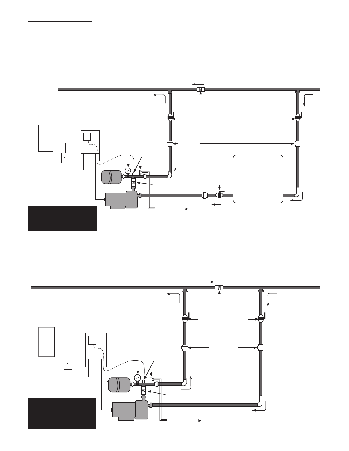
The following diagrams show a typical system using the Aquavar ABII Constant Pressure System. Connection can be
made directly to a water supply or water can be drawn from a supply tank. Diagram #1 shows a typical set up for a
supply tank.
Home Supply
Aquavar ABII
Controller
Circuit
Breaker
Disconnect
Diagram 1
Aquavar ABII Installation
for Well Pump System
Transducer
Gauge
Tank
Motor/Pump
Relief
Valve
Check Valve
(not included)
To Drain
Check Valve
Isolation Valves
Unions
Isolation
Valve
Well Supply
Atmospheric
Storage Tank
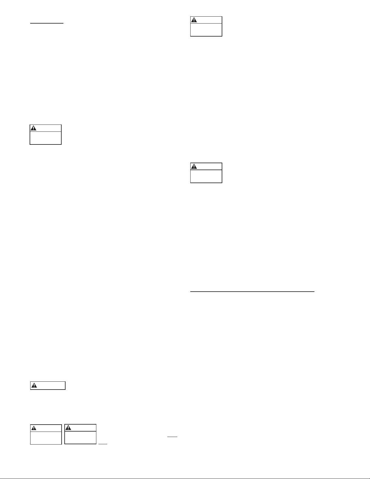
Diagram #2 shows a set-up for municipal water connection. This allows pump maintenance without main line shut-off.
Home Supply Water Main
Check Valve
Aquavar ABII
Isolation Valves
Controller
Circuit
Breaker
Unions
Transducer
Disconnect
Diagram 2
Aquavar ABII
Installation for
Municipal Water System
4
Gauge
Tank
Motor/Pump
Relief
Valve
Check Valve
(not included)
To Drain
Note: A check
valve or double
check valve may
be required on
the suction side
of the pump.
Consult local
codes.
Page 5
Hazardous
Pressure
CAUTION
WARNING
Hazardous
voltage
Hazardous
Pressure
CAUTION
WARNING
Hazardous
Pressure
CAUTION
Hazardous
Pressure
CAUTION
4: PIPING
4: PIPING
General
NOTE: All plumbing work must be performed by a
qualied technician. Always follow all local, state and
provincial codes.
A proper installation requires a pressure relief valve, a ¼"
female N.P.T. threaded tting (found on tank tee) for the
pressure sensor, and properly sized pipe. Piping should
be no smaller than the pump discharge and/or suction
connections. Piping should be kept as short as possible.
Avoid the use of unnecessary ttings to minimize friction
losses.
Some pump and motor combinations
supplied with this system can create over
200 PSI. Select pipe and ttings accordingly
per your pipe suppliers’ recommendation. Consult local
codes for piping requirements in your area.
All joints must be airtight. Use Teon tape or another
type of pipe sealant to seal threaded connections. Please
be careful when using thread sealant as any excess that
gets inside the pipe may plug the pressure sensor.
Galvanized ttings or pipe should never be connected
directly to the stainless steel discharge head or casing
as galvanic corrosion may occur. Barb type connectors
should always be double clamped.
Pressure Tank, Pressure Relief Valve and
Discharge Piping
The standard Hydro-Pro tanks have a pre-charge of 38
PSI. Set the tank pressure, while tank is empty of water,
to 20 psi below the desired system pressure setting.
Ex. for a 50 psi system pressure, charge the tank to 30
psi. Use a higher tank pre-charge setting if the system
drifts over 5 PSI at a constant ow rate. Use only “precharged” tanks on this system. Do not use galvanized
tanks. Select an area that is always above 34º F (1.1º
C) in which to install the tank and pressure relief valve.
If this is an area where a water leak or pressure relief
valve blow-off may damage property, connect a drain
line to the pressure relief valve. Run the drain line from
the pressure relief valve to a suitable drain or to an area
where water will not damage property. Use the supplied
tank tee to connect the discharge pipe to the pressure
tank and house plumbing. It is allowable to pump to
multiple locations.
Maximum working pressure of most HydroPro tanks is 125 psi. Check the tank
label or instruction manual to verify data.
Installing the Pump
WARNING: Risk of electric
shock - This pump system has
not been investigated for use
in swimming pool areas.
Plumb suction and discharge of pump into
piping. Locate the pump as near liquid
source as possible. When pumping out of
an atmospheric tank locate the pump below the level
of the liquid in the tank. All piping must be supported
independently of the pump. Be sure that suction
and discharge piping are in line with the suction and
discharge of the pump. Install a check valve between
the discharge of the pump and the pressure sensor and
tank. For additional information refer to Installation,
Operation and Maintenance Instructions supplied with
the pump.
Installing the Pressure Sensor
Install the pressure sensor in the tank tee provided with
the unit. The pressure sensor cable supplied with the
controller is 120 inches long. Locate the controller so
there will be enough cable to properly install the pressure
sensor.
Do not install any shut-off valves, lters or
ow/pressure control devices (except for
a check valve) between the pressure sensor and the discharge of the pump as this could create a
hazardous situation.
Use ONLY the pressure sensor provided with the unit.
Install the pressure sensor into one of the ¼" holes on the
tank tee provided in the kit. Install the pressure sensor
vertically to avoid accumulation of debris in the sensor
port. Do not install the tank tee with the ¼" holes facing
down. Align the connector on the end of the pressure
sensor cable with the mating connector on the pressure
sensor and push it on. The tab will lock it in place.
Prevent water from following the cable and entering
sensor connector by creating a “drip loop” in the cable.
5: MOUNTING THE CONTROLLER
5: MOUNTING THE CONTROLLER
General
Mount the controller in a well ventilated, shaded area
using the supplied mounting kit. The controller must be
mounted vertically. Be sure to leave 8 inches of free air
space on every side of the unit. The controller must be
in an area with an ambient between 34º F (1.1º C) and
104º F (40º C). Model 2AB2 will automatically decrease
(derate) the maximum output current of the drive (6.9A)
if the ambient temperature exceeds 104º F
(40º C). The maximum output current of the drive will
be decreased by 0.069A for every degree Fahrenheit
above 104º F, or -1%/º F. The maximum output current
of the drive will be decreased by 0.12A for every degree
Celsius above 40º C, or -1.75%/º C. Model 1AB2
does not require ambient derating and will maintain
a maximum output current of 4.2A in high ambient
temperatures. If installation is more than 3300 feet above
sea level, drive output should also be derated by 2% per
1000 feet above 3300 feet.
NOTE: Do not block the heat sink (ns) and do not
set anything on the units.
5
Page 6
The controller access cover should always
WARNING
Hazardous
voltage
Hazardous
voltage
DANGER
Hazardous
voltage
DANGER
Hazardous
voltage
DANGER
Hazardous
voltage
DANGER
Hazardous
voltage
DANGER
Hazardous
voltage
DANGER
Hazardous
voltage
DANGER
CAUTION
be securely fastened to the control box
due to the dangerous voltage/shock hazard
inside the unit.
6: POWER SUPPLY AND WIRING
6: POWER SUPPLY AND WIRING
Power Supply
The 1151AB2 Controller requires a single
phase power supply of 115 volts +/– 15%.
The 1AB2 and 2AB2 Controllers require
a single phase power supply of 230 volts +/– 15%. All
controllers require a dedicated 20 amp two-pole circuit
breaker. A dedicated circuit means no other appliances
use the same circuit! The output power from the motor
controller is three-phase, variable frequency and variable
voltage. Maximum output voltage and frequency are
line input voltage and 60 Hz, respectively. Low supply
voltage will reduce pump performance.
NOTE: Installation and maintenance MUST be performed by properly trained and qualied personnel.
Always follow the National Electric Code or Canadian
Electric Code, as well as all local, state and provincial
codes when wiring the system.
Wire and Conduit
Do not use wire smaller than 14 AWG. Use of
Metal Conduit with Metal Conduit Connectors is
recommended for all electrical connections.
Output Power Connections
Connect the motor leads for 230 volt or
208 volt operation using the nameplate as a
reference. Connect the output power leads
from the controller to the 3 motor leads in the conduit
box on the motor. Connect the ground (green) output
power lead to the ground screw in the conduit box on
the motor. This step is performed in its entirety at the
factory for complete systems. See diagram 4 for details.
NOTE: If the pump has more than 50 feet of wire
from the controller, consult factory for selection of an
output load lter (load reactor).
to properly ground the controller or motor will create an
electrical shock hazard.
NOTE: Do not use GFCI protection with this controller. Nuisance tripping will result.
7: STARTING THE SYSTEM
7: STARTING THE SYSTEM
Status Code Indicator Light is not a voltage
indicator! Always turn off disconnect switch
and circuit breaker before servicing.
Once the controller is powered it will remain electrically charged for 5 minutes after
power is turned off. Wait 5 minutes after
disconnecting power before opening controller access
cover as there is a severe shock hazard.
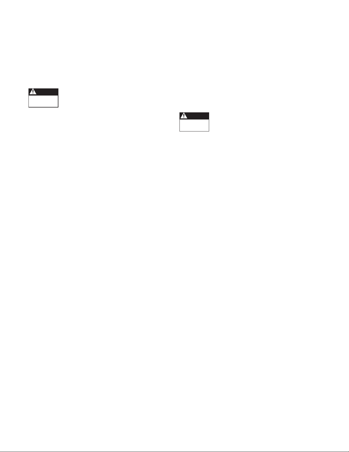
Setting the Motor Overload Switches
When the unit is powered, the Motor Over-
load Setting Switches are at a high voltage
potential. DO NOT touch the Motor Overload Setting Switches while the power is on.
The Motor Overload Setting Switches adjust the level
of motor overload current protection needed to protect
the motor from damage due to overcurrent conditions.
Turn the circuit breaker and disconnect switch to the off
position, and wait 5 minutes. Remove controller access
cover. On the inside of the access cover is the Motor
Overload Setting table.
shows the switch setting for the desired Motor Overload
Setting. Read the Service Factor Amps off the motor
nameplate. Use the Motor Overload Setting table to
match the Service Factor Amps (SF Amps) of the motor
to the correct switch setting.
the Motor Overload Switches according to the correct
combination on the table. If the Service Factor Amps
of the motor do not match any of the Motor Overload
Settings, use the next lowest switch setting.
for details
.
NOTE: The Motor Overload Setting Switches are
preset at the factory for complete systems.
See Diagram 6 for details.
This table
See Diagram 5 for details.
See Diagram 3
Set
Connecting Input Power
Connect the single-phase power supply
leads and Safety Ground wire from a 20
amp two-pole circuit breaker (in the OFF
position) to one side of a 20-amp two-pole disconnect
switch. Connect the input power leads supplied with
the controller to the other side of the disconnect switch.
Be sure to use Metal Conduit with Metal Conduit
Connectors for electrical connections.
The controller has a high leakage current
to ground. The terminals marked "GND"
in the controller must be connected to the
safety ground from the electrical service entrance. Failure
6
Failure to perform this step will result in
loss of Motor Overload Protection and
will void the Motor Warranty. Nuisance Motor Overload Error tripping or motor damage can occur if these
switches are not set properly.
Setting the Pressure
Turn the circuit breaker and disconnect switch to the off
position, and wait 5 minutes. Remove controller access
cover. Open a faucet in the system and turn the breaker/
disconnect switch to the ON position. The pump will
start and pressure will increase to the factory preset 50
PSI. After the pressure has stabilized, use the Increase/
Decrease Pressure Adjust Pushbuttons on the right-hand
side of the controller to adjust the pressure setting.
Page 7
Push and Hold the Increase or Decrease Pressure Adjust
Hazardous
voltage
DANGER
Hazardous
voltage
DANGER
Pushbutton until the desired pressure setting is reached.
The new pressure setting is automatically saved. Close
the faucet and turn power to controller off. Wait 5
minutes before installing the controller access cover.
NOTE: The maximum allowable pressure setting is
85 psi.
NOTE: It is possible for the pump to maintain
constant pressure with a low ow or a high positive
suction head even if the pump is rotating backwards.
While the pump is running, use an amp probe on one
of the output power leads connected to the motor and
compare the current draw between the two rotation
directions. The lowest current reading indicates the
pump is running in the correct direction.
Setting the Application Switches
When the unit is powered, the Application
Setting Switches are at a high voltage potential. DO NOT touch the Application Setting
Switches while the power is on.
The controller has 6 possible Application Settings.
These settings are used to adjust the Minimum Speed
of the motor and the Ramp Setting, or acceleration and
deceleration ramp. This allows the controller to t a wide
range of applications.
Before adjusting the Application Switches, turn the
circuit breaker and disconnect switch to the off position.
Wait 5 minutes. Remove the controller access cover. On
the inside of the access cover is the Application Switch
Setting Table. See Diagram 6 for details. This table shows
the switch setting needed for the desired system response.
See Diagram 3 for details.
Select a Minimum Speed of 10 Hz if the pressure at the
pump’s suction is within 20 PSI of the desired pressure
setting. Select a Minimum Speed of 30Hz if the pressure
at the pump’s suction is more than 20 PSI below the
desired pressure setting, if pumping from a tank or if
drawing a suction lift.
Changing the Ramp Setting changes how fast the
controller can change the speed of the motor. A Slow
Ramp Setting allows the controller to work better in
applications where the average demand for water is low
(less than 3GPM or about 1 faucet). A Fast Ramp Setting
allows the controller to work better in applications
where the demand for water is high because the motor is
allowed to change speed faster.
System Status
The controller is always powered. A Solid Green Status
Code indicates that the pump is in standby mode (pump
not running) or that the line input voltage is low.
Status Code Indicator Light is not a voltage
indicator! Always turn off disconnect switch
and circuit breaker and wait 5 minutes
before servicing.
A Blinking Green Status Code indicates that the pump
is running. A Blinking or Solid Red Light indicates a
problem with the controller. Refer to the access cover
side panel or Diagram 6 for Status Codes. See Section 9
for more details.
NOTE: The Application Switches are preset at the
factory to “0000” or Minimum Speed = 30 Hz, Ramp
Setting = Fast.
Motor Rotation Direction
If the pressure or ow seems low, check motor rotation
direction. Turn the circuit breaker and disconnect
switch to the off position, and wait 5 minutes. Switch
any two leads on the controller output (T1, T2, or T3).
Turn the circuit breaker and disconnect switch to the on
position. Observe pressure and ow. If pressure or ow
still seems low check plumbing.
7
Page 8
Hazardous
voltage
DANGER
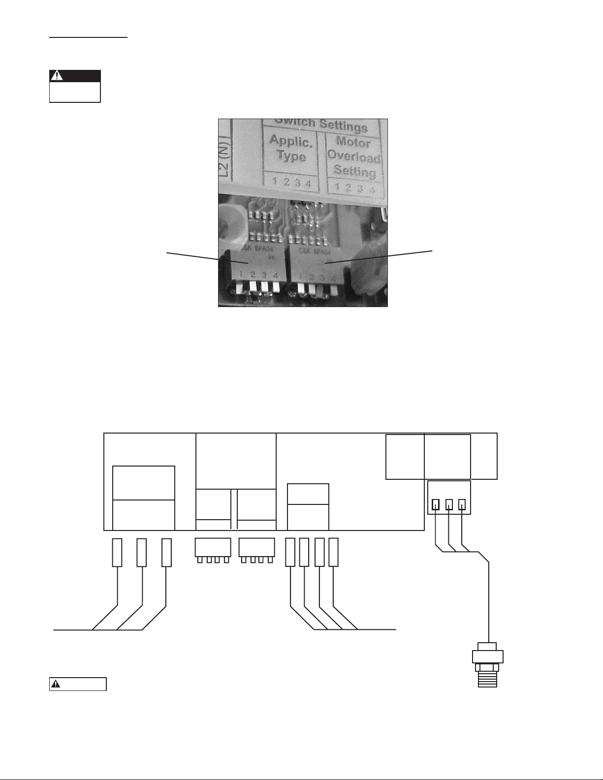
Input
1 Phase
GND
L1
L2 (N)
See Manual For
Switch Settings
Applic.
Type
Output
To Motor
1 2 3 4 1 2 3 4
Pressure
Sensor
Input (Wht)
+5V (Red)
Com. (Blk)
T1T2T3
GND
Motor
Overload
Setting
Line output to motor.
Correct motor rotation
determines order of colors.
Pressure
Sensor
9K518
Line input power from
2-pole disconnect or
circuit breaker.
GREEN
BLACK
BLACK
GREEN
WHITE
RED
BLACK
BLUE
RED
BLACK
8: DIAGRAMS
WARNING
8: DIAGRAMS
Motor Overload and Application Switch Setting
When the unit is powered, the Motor Overload and Application Setting Switches are at a high voltage
potential. Always turn off the disconnect switch and circuit breaker and wait 5 minutes before touching
the Motor Overload or Application Setting Switches.
Application Switch Setting
See chart that follows for
correct switch settings.
Aquavar ABII Wiring Diagram
Motor Overload Setting
Switches
See chart that follows for
correct switch settings.
Diagram 3
8
Do not connect 230V to a 115V controller. This will
damage the controller and voids the warranty.
Diagram 4
Page 9
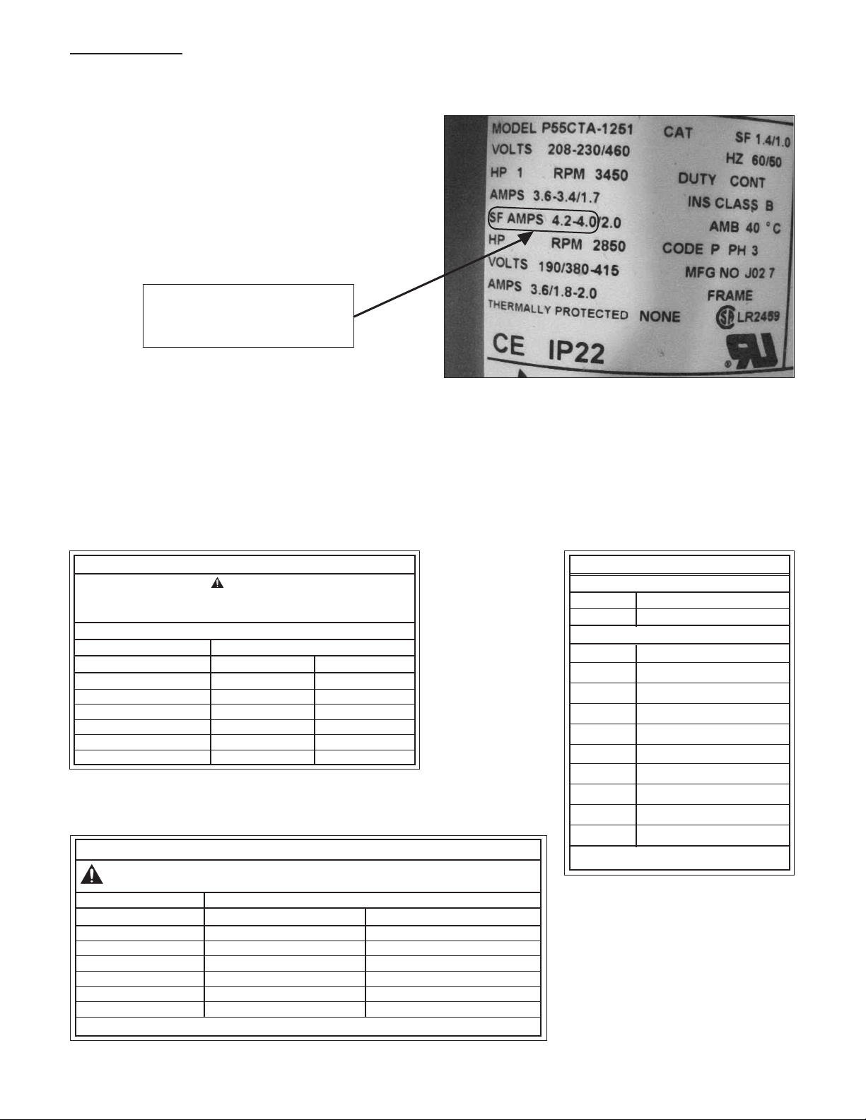
8: DIAGRAMS
8: DIAGRAMS (continued)
Typical Motor Nameplate Showing Service Factor Amps (SF AMPS)
Service Factor Amps (SF AMPS)
that are used to set the Motor
Overload Setting Switches.
In this example, use the 4.2 Amp setting indicated on the Motor Overload Setting Table. This setting is used to account
for any voltage uctuation.
Diagram 5
Labels found on the Controller Access Cover:
Motor Overload Setting
WARNING
Disconnect Power And Wait For LED Indicator To Turn
Off Before Touching Motor Overload Setting Switches.
1 = UP 0 = DOWN
DIP Switch Setting Motor Overload Setting (Amps)
1 2 3 4 1AB2 2AB2
1 1 1 1 2.5 4.6
1 1 1 0 2.8 5.2
1 1 0 1 3.3 5.3
1 0 1 1 3.5 5.8
0 1 1 1 3.8 6.5
0 0 0 0 4.2 6.9
Motor Overload Setting Label
Use this label to choose the correct Motor Overload Switch
Setting. This label is found under the controller access cover.
Application Type Switch Setting
WARNING
DIP Switch Setting 1 = UP 0 = DOWN
1 2 3 4 Minimum Speed (Hz) Ramp Setting
1 1 1 1 * 10 Slow
1 1 1 0 * 10 Medium
1 1 0 1 * 10 Fast
1 0 1 1 30 Slow
0 1 1 1 30 Medium
0 0 0 0 30 Fast
*THESE SETTINGS ARE NOT TO BE USED WITH SUBMERSIBLE PUMPS.
Disconnect Power And Wait For LED Indicator To Turn
Off Before Touching Application Setting Switches.
Status Code
to diagnose any
system errors.
Label
Use this label
This label is
found on the
side of the
controller
access cover.
Status Codes*
Green Light Codes
Constant Standby/Low Voltage
Blinking Pump Running
Red Light Codes
Constant Replace Controller
1 Blink No Water/Loss Of Prime
2 Blinks Tank Water-Logged
3 Blinks Pressure Sensor Fault
4 Blinks Pump or Motor Bound
5 Blinks Short Circuit
6 Blinks Ground Fault
7 Blinks High Temperature
8 Blinks Over Voltage (>264V)
9 Blinks Motor Overload
*No Light - No/Very Low Voltage
Application Switch Setting Label
Use this label to choose the correct
Application Switch Setting. This label is
found under the controller access cover.
Diagram 6
9
Page 10
Hazardous
voltage
DANGER
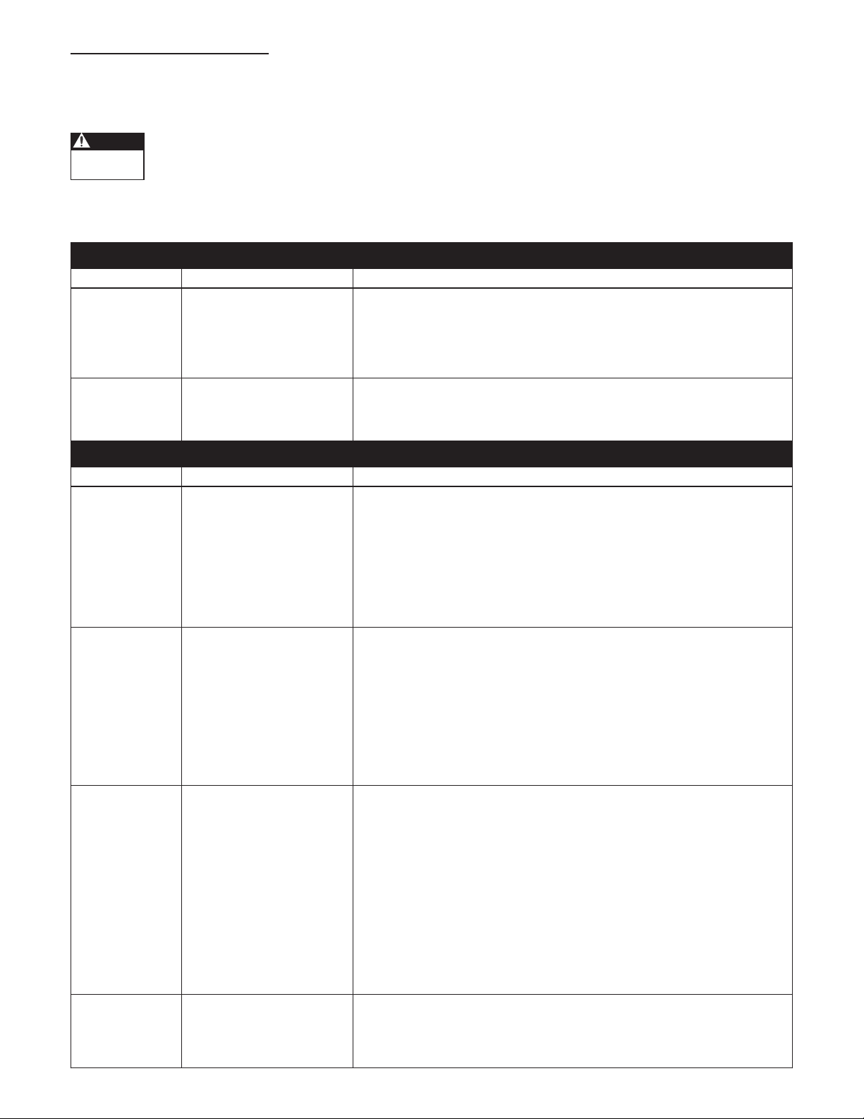
9: TROUBLESHOOTING
9: TROUBLESHOOTING
General
The Aquavar ABII is a self-diagnosing controller. If a problem occurs, observe the Status Code Indicator Light on the
front of the unit. No Status Code Indicator Light means either no or low input voltage (less than 50 V).
Status Code Indicator Light is not a voltage indicator! Always turn off disconnect switch and circuit
breaker and wait 5 minutes before servicing. High voltage may still remain on controller.
Refer to the status code label on the side of the controller access cover to diagnose system errors. See Diagram 6 for details.
USE THE FOLLOWING TABLE TO HELP TROUBLESHOOT PROBLEMS.
GREEN LIGHT CODES
Indicator Code Status Description
Constant Standby/Low Voltage Constant Green Light indicates the pump is off. The system is in
Standby mode when there is no ow in the system and the pressure
setting has been reached. The system is in a Low Voltage condition
when the line input voltage drops below 196VAC for 1AB2 and 2AB2
controllers and 98VAC for 1151AB2 controllers.
Blinking Pump Running Flashing Green Light indicates the pump is running. If pump is not
running, turn off power to controller and wait 5 minutes. Check
output power connections from controller to motor.
RED LIGHT CODES
Constant Controller Error Replace Aquavar ABII Controller
1 Blink No Water/Loss Of Prime This fault is indicated if the system pressure drops 5 PSI or more
below the set pressure and the output current is less than 75% of the
motor overload setting for 10 seconds. The system will automatically
restart in 5 minutes. If 3 faults occur in an hour, the system will not
restart and will need to be manually reset. If the problem reoccurs,
please verify supply capacity, pump capacity, proper setting of the
motor overload switches and that there are no restrictions between
the supply and the pump.
2 Blinks Tank Water-Logged This warning is indicated if there is a drastic drop in system pressure
in a short amount of time. The warning will not impact operation.
The pump will continue to run. This warning can be caused by low air
pressure in the tank or the tank bladder may have failed. This can also
be caused by extreme changes in ow. The error is cleared each time
the pump starts. If the error reoccurs often, check the air pressure in
the tank. Before checking tank air pressure, turn power to control off
to prevent pump from turning on. Relieve system pressure by opening
a faucet.
3 Blinks Pressure Sensor Fault This fault indicates a problem with the pressure sensor feedback.
Verify the connections from the Aquavar ABII Controller to the
pressure sensor. Turn power to controller off and wait 5 minutes.
Remove controller access panel. Be sure sensor cable is wired as
shown in Diagram 4. If cable is wired correctly, check the voltage on
the Input (White) pressure sensor terminal connection in the
Aquavar ABII controller. Using a DC voltmeter, connect the positive
lead to the Input (White) pressure sensor terminal connection, connect
the negative lead to the Com. (Black) pressure sensor terminal
connection. Turn power to controller on. The DC voltage measured
should be in the valid range of 0.5 Vdc to 4.5 Vdc (+/- 0.2 Vdc). If the
voltage is outside this range, replace pressure sensor.
4 Blinks Pump or Motor Bound This fault can be caused by mechanical binding from debris in pump
or from an electrical failure in the motor. Verify the error by turning
power to controller off for 1 minute and then on. Pump must be
checked if error persists.
10
Page 11
9: TROUBLESHOOTING
(135.36)
5.33
(259.08)
10.20
(237.06)
9.33
(12.07)
.48
(157.90)
6.22
(135.36)
5.33
(135.36)
5.33
(259.08)
10.20
(237.06)
9.33
(12.07)
.48
(157.90)
6.22
(114.30)
4.50
(57.15)
2.25
(81.28)
3.20
(16.51)
.65
9: TROUBLESHOOTING (continued)
Indicator Code Status Description
5 Blinks Short Circuit Check wiring for shorting phase to phase and phase to ground. Turn
power to controller off and wait 5 minutes. Remove controller
access panel. Disconnect motor leads marked T1, T2, and T3. Measure
resistance between all motor leads using an ohmmeter. NOTE: Motor
winding resistance is typically 2 to 10 OHMS depending on motor.
6 Blinks Ground Fault Check wiring for shorting phase to ground. Turn power to controller
off and wait 5 minutes. Remove controller access panel. Disconnect
motor leads T1, T2, T3, and Ground from controller. Measure
resistance between all motor leads and ground using a Megohmmeter.
Connect one Megohmmeter lead to any one of the motor leads and
the other to ground lead. Set Megohmmeter to 500V DC output.
Resistance readings less than 500,000 ohms or 0.5 Megohms indicate
a damaged motor.
7 Blinks High Temperature This fault is caused by a high temperature inside of the controller. The
controller will shut off when the temperature inside the controller
reaches 158º F (70º C). The controller will turn back on when the
temperature inside the controller reaches 150º F (65.5º C). Avoid
installing the controller where ambient temperatures exceed 104º F
(40º C). Avoid installing the controller where it is exposed to direct
sunlight.
8 Blinks Over Voltage Measure input voltage using an AC voltmeter. Connect the positive
and negative leads to L1 and L2 on the Aquavar ABII controller. Verify
line input voltage is not greater than 264 VAC for 1AB2 and 2AB2
controllers and 132VAC for 1151AB2.
9 Blinks Motor Overload This fault is indicated when the current supplied to the motor exceeds
the Motor Overload Setting on the Aquavar ABII controller. Refer to
Section 7, Setting the Motor Overload DIP Switches for details. If
switches are set according to Section 7, check motor.
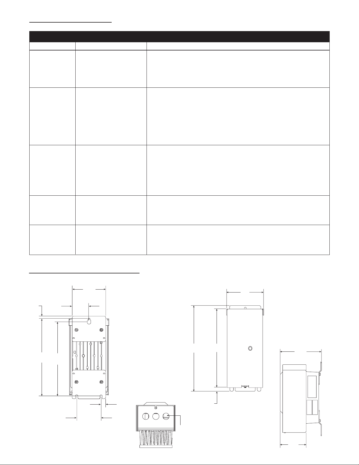
10: CONTROLLER DIMENSIONS
10: CONTROLLER DIMENSIONS
RED LIGHT CODES
(8.38)
.33
(242.04)
9.53
(232.56)
9.16
(57.15)
2.25
(114.30)
4.50
(81.28)
3.20
(16.51)
.65
Liquid
Tight
(135.36)
5.33
(12.07)
.48
(237.06)
9.33
(99.06)
3.90
(157.90)
6.22
(259.08)
10.20
1
∨2”
11
Page 12

LIMITED WARRANTY
This warranty applies to this Xylem Inc. product.
Any part or parts found to be defective within the warranty period shall be replaced at no charge to the dealer during the warranty period. The warranty period shall exist for a
period of twenty-four (24) months from date of installation or thirty (30) months from date of manufacture, whichever period is shorter.
A dealer who believes that a warranty claim exists must contact the authorized Xylem Inc. distributor from whom the equipment was purchased and furnish complete details
regarding the claim. The distributor is authorized to adjust any warranty claims utilizing the Xylem Inc. Customer Service Department.
The warranty excludes:
(a) Labor, transportation and related costs incurred by the dealer;
(b) Reinstallation costs of repaired equipment;
(c) Reinstallation costs of replacement equipment;
(d) Consequential damages of any kind; and,
(e) Reimbursement for loss caused by interruption of service.
For purposes of this warranty, the following terms have these definitions:
(1) “Distributor” means any individual, partnership, corporation, association, or other legal relationship that stands between Xylem Inc. and the dealer in purchases, consignments
or contracts for sale of the subject equipment.
(2) “Dealer” means any individual, partnership, corporation, association, or other legal relationship which engages in the business of selling or leasing equipment to customers.
(3) “Customer” means any entity who buys or leases the subject equipment from a dealer. The “customer” may mean an individual, partnership, corporation, limited liability
company, association or other legal entity which may engage in any type of business.
THIS WARRANTY EXTENDS TO THE DEALER ONLY.
Xylem, Inc.
2881 East Bayard Street Ext., Suite A
Seneca Falls, NY 13148
Phone: (800) 453-6777
Fax: (888) 322-5877
www.centripro.com
CentriPro and Aquavar ABII are trademarks of Xylem Inc. or one of its subsidiaries.
© 2012 Xylem Inc. IM156 Revision Number 6 February 2013
Page 13

MANUAL DE INSTRUCCIÓN
U
®
C
MODELOS CUBIERTOS:
1151AB2 (115V, 4.2A), 1AB2 (230V, 4.2A),
IM156R06
L
US
2AB2 (230V, 6.9A)
Controlador Aquavar ABII
CONTROL DE BOMBA DE VELOCIDAD VARIABLE
MANUAL DE INSTALACIÓN, OPERACIÓN Y RESOLUCIÓN DE PROBLEMAS
Page 14

Información del propietario
Información del propietario
Tabla de contenido
Tabla de contenido
Número de Modelo del Controlador:
Número de serie del Controlador:
Número de modelo de la Bomba:
Número de serie de la Bomba:
Número de modelo del motor de la Bomba:
SFA del motor:
Número de serie del Tanque:
Instalador:
Número de teléfono del instalador:
Fecha de instalación:
Largos de cable (pies)
Entrada de servicio al controlador:
Controlador al motor:
Tensión de entrada:
ASUNTO PÁGINA
1. Instrucciones importantes de seguridad ................. 15
2. Componentes del sistema ...................................... 15
3. Diseño del sistema ................................................. 16
4. Tuberías ................................................................. 17
5. Montaje del controlador ........................................ 17
6. Fuente de alimentación y cableado ........................ 18
7. Arranque del sistema ........................................ 18-19
8. Diagramas ........................................................ 20-21
9. Identicación y resolución de problemas .......... 22-23
10. Dimensiones del controlador ................................. 24
11. Garantía limitada ................................................... 24
AVISO: REGISTRE LOS NÚMEROS DE MODELO
Y DE SERIE DE LA BOMBA Y DEL CONTROLADOR EN ESTE MANUAL DE INSTRUCCIONES PARA CONSULTA FUTURA.
DÉSELO AL PROPIETARIO O SUJÉTELO
AL CONTROLADOR AL FINALIZAR LA
INSTALACIÓN.
NOTA:
• Utilice exclusivamente cables de cobre.
• Adecuado para usarse en un circuito que pueda suministrar 5000 RMS
de amperes simétricos. Los circuitos de derivaciones están protegidos por
medio de fusibles.
• Adecuado para usarse en un microambiente con una contaminación del
grado 2.
• La protección de sobrecarga del motor está establecida a 110% de la
corriente nominal.
14
• Para poder conservar la clasicación ambiental de la cubierta, se deben
cerrar todas las aperturas de los equipos con clasicación 3, 3R, RS, 4,
4X, 6 o 6P.
• La temperatura ambiental que se admite como máximo es de 50°C.
Page 15

Tensión
p
eligrosa
PELIGRO
Presión
Peligrosa
CUIDADO
PELIGRO
ADVERTENCIA
1: INSTRUCCIONES DE SEGURIDAD
ADVERTENCIA
Tensión
peligrosa
Presión
Peligrosa
PRECAUCIÓN
1: INSTRUCCIONES DE SEGURIDAD
PARA EVITAR LESIONES PERSONALES GRAVES
O FATALES O DAÑOS SIGNIFICATIVOS A LA
PROPIEDAD, LEA Y RESPETE TODAS LAS INSTRUCCIONES DE SEGURIDAD EN EL MANUAL Y
EN EL EQUIPO.
LA FINALIDAD DE ESTE MANUAL ES AYUDAR EN
LA INSTALACIÓN Y OPERACIÓN DE ESTA UNIDAD Y SE DEBE GUARDAR EL MISMO CON LA
UNIDAD.
Este es un SÍMBOLO DE ALERTA DE
SEGURIDAD. Al ver este símbolo en la
bomba, el controlador o en el manual,
busque una de las siguientes palabras de
señal y esté alerta al potencial de lesión
personal o daños a la propiedad.
Indica una situación posiblemente
peligrosa la cual, si no se evita, podría
producir lesiones graves o aún la
muerte.
Indica una situación inminentemente
peligrosa la cual, si no se evita,
producirá lesiones graves o aún la
muerte.
PRECAUCIÓN
Indica una situación posiblemente
peligrosa la cual, si no se evita,
podría producir lesiones menores o
moderadas.
PRECAUCIÓN
Utilizado sin un símbolo de alerta
de seguridad indica una situación
posiblemente peligrosa la cual, si no se
evita, podría causar daños materiales.
NOTA: INDICA INSTRUCCIONES ESPECIALES
QUE SON MUY IMPORTANTES Y
DEBEN SER SEGUIDAS.
LEA DETENIDAMENTE TODAS LAS INSTRUCCIONES Y ADVERTENCIAS ANTES DE REALIZAR CUALQUIER TRABAJO EN ESTE CONTROLADOR.
MANTENGA TODAS LAS CALCOMANÍAS DE
SEGURIDAD.
EL PERSONAL DE OPERACIONES DEBE
LEER, ENTENDER Y SEGUIR TODAS LAS
INSTRUCCIONES DE OPERACIÓN. CENTRIPRO
NO ACEPTA NINGUNA RESPONSABILIDAD
POR DAÑOS Y PERJUICIOS O PROBLEMAS DE
FUNCIONAMIENTO QUE SEAN EL RESULTADO
DE NO CUMPLIR CON LAS INSTRUCCIONES DE
OPERACIÓN.
1. El objetivo de este manual es ayudar en la instalación,
operación y reparación del sistema y debe ser mantenido con el mismo.
2. La instalación y el mantenimiento DEBEN ser realizados por personal apropiadamente capacitado y competente.
3. Revise todas las instrucciones y advertencias antes de
realizar cualquier trabajo en el sistema.
4. No DEBE quitarse ningún rótulo de seguridad de la
bomba o del controlador.
5. El sistema DEBE desconectarse de la
fuente de alimentación principal antes de
intentar cualquier operación o mantenimiento en la sección eléctrica o mecáni-
ca del sistema. Si no se desconecta la corriente antes
de intentar realizar operaciones o mantenimiento, se
pueden producir quemaduras, electrochoque o aún la
muerte.
6. Cuando están en operación, el motor y
la bomba podrían arrancar inesperadamente y producir lesiones graves.
2: COMPONENTES DEL SISTEMA
2: COMPONENTES DEL SISTEMA
Inspeccione los componentes del sistema Aquavar ABII
y asegúrese de que tenga todas las partes y que esté
familiarizado con sus nombres. Asegúrese de inspeccionar
todos los componentes suministrados por CentriPro para
determinar si resultaron dañados durante el envío.
Aquavar ABII:
1. Bomba con motor
2. Controlador Aquavar ABII con cable de sensor de
presión integral
3. Tanque de presión (provisto en algunos modelos)
4. Sensor de presión
5. Juego de montaje
6. Perl T de tanque con tapón para tubo
7. Indicador de presión
ADVERTENCIA
NO energice la unidad ni haga funcionar
la bomba hasta que se hayan completado todas las conexiones eléctricas y
de tuberías, especialmente la conexión
del sensor de presión. La bomba no
debe hacerse funcionar en seco. Todo el
trabajo eléctrico debe ser realizado por
un técnico calicado. Siempre siga el Código Eléctrico
de EE.UU. (NEC) o el Código Eléctrico Canadiense
(CSA), además de todos los códigos locales, estatales
y provinciales. Las preguntas acerca del código deben
ser dirigidas al inspector eléctrico local. Si se hace caso
omiso a los códigos eléctricos y normas de seguridad
de OSHA, se pueden producir lesiones personales o
daños al equipo. Si se hace caso omiso a las instrucciones de instalación del fabricante, se puede producir
electrochoque, peligro de incendio, lesiones personales o aún la muerte, daños al equipo, rendimiento
insatisfactorio y podría anularse la garantía del fabricante.
15
Page 16

3: DISEÑO DEL SISTEMA
3: DISEÑO DEL SISTEMA
NOTA: Los sistemas DEBEN ser diseñados por técnicos capacitados únicamente y cumplir con todos los re-
querimientos de los códigos estatales y locales correspondientes.
Los siguientes diagramas muestran un sistema típico que utiliza el sistema de presión constante Aquavar ABII. Puede
hacerse la conexión directamente a un suministro de agua o puede extraerse agua de un tanque de suministro. El
diagrama #1 muestra una instalación típica de un tanque de suministro.
Suministro domiciliario
Control
Aquavar ABII
Cortacircuito
Disyuntor
Diagram 1
Instalación Recomendada
de Aquavar ABII para
Sistemas de Bombas
de Pozo
Manómetro
Gauge
Tanque
Motor/Pump
Válvulas de retención
Válvula de aislamiento
Empalmes
Válvula de
desahogo
Válvulas de retención
(no incluida)
Drenaje
Válvula de
aislamiento
Suministro de pozo
Tanque de
almacena-
miento
atmosférico
El diagrama #2 muestra una instalación típica para una conexión de agua municipal. Esto permite mantener la bomba
sin tener que cerrar la línea principal.
Suministro domiciliario
Suministro de pozo
Válvulas de retención
Válvula de
Control
aislamiento
Aquavar ABII
Corta-
circuito
Empalmes
Manómetro
Disyuntor
Diagram 2
Instalación
Recomendada de
Aquavar ABII para Sistemas de Agua Municipal
16
Gauge
Tanque
Motor/Pump
Válvula de
desahogo
Válvulas de retención
(no incluida)
Drenaje
Nota: Puede
ser necesaria
una válvula de
verificación
o válvula de
verificación doble
en el lado de
succión de la
bomba. Consulte
los códigos
locales.
Page 17
ADVERTENCIA
Presión
Peligrosa
PRECAUCIÓN
ADVERTENCIA
Tensión
peligrosa
Presión
Peligrosa
PRECAUCIÓN
Presión
Peligrosa
PRECAUCIÓN
Presión
Peligrosa
PRECAUCIÓN
4: TUBERÍAS
4: TUBERÍAS
Generalidades
NOTA: Todo el trabajo de plomería debe ser realizado
por un técnico calicado. Siempre cumpla con todos
los códigos locales, estatales y provinciales.
Una instalación apropiada requiere una válvula de alivio
de presión, un accesorio roscado N.P.T. hembra de ¼
pulgada (encontrado en el perl T del tanque) para el
sensor de presión y tubería de tamaño apropiado. La
tubería no debe ser más pequeña que las conexiones
de descarga o succión de la bomba. La tubería debe
mantenerse lo más corta posible. Evite utilizar accesorios
innecesarios para reducir al mínimo las pérdidas por
fricción.
Algunas combinaciones de bomba y motor
suministradas con este sistema pueden crear
más de 200 PSI. Seleccione las tuberías
y accesorios de acuerdo con la recomendación de su
proveedor de tuberías. Consulte los códigos locales con
respecto a requisitos de tuberías en su área.
Todas las juntas deben ser herméticas. Utilice cinta de
Teon u otro tipo de sellador de tubos para sellar las
conexiones roscadas. Tenga cuidado cuando utilice
sellador de roscas ya que cualquier exceso que entre a la
tubería podría tapar el sensor de presión.
Los accesorios o tuberías galvanizadas nunca deben
conectarse directamente a la carcasa o al cabezal de
descarga de acero inoxidable ya que podría producirse
corrosión galvánica. Los conectores tipo arpón siempre
deben sujetarse con doble abrazadera.
Tanque de presión, válvula de alivio de presión
y tubería de descarga
Los tanques Hydro-Pro estándar tienen una carga
previa de 38 PSI. Fije la presión del tanque, mientras
que el tanque está vacío del agua, a 20 PSI debajo de
la conguración deseada de la presión de sistema. Por
ejemplo, para una presión de sistema de 50 PSI, cargue el
tanque a 30 PSI. Utilice el valor más alto de precarga del
tanque si la presión del sistema varía más de 5 lbs./pulg.
cuadrada a una velocidad de ujo constante. Utilice sólo
tanques “precargados” en este sistema. No utilice tanques
galvanizados. Seleccione un área que siempre esté a más
de 34º F (1.1º C) en la cual instalar el tanque y la válvula
de alivio de presión. Si éste es un lugar donde una fuga
de agua o purga de la válvula de alivio de presión podría
producir daños materiales, conecte una línea de drenaje
a la válvula de alivio de presión. Conecte una línea de
drenaje desde la válvula de alivio de presión a un drenaje
apropiado o a un lugar donde el agua no produzca daños
materiales. Utilice el perl T del tanque suministrado
para conectar la tubería de descarga al tanque de presión
y la cañerías de la casa. Se puede bombear a lugares
múltiples.
La presión máxima de funcionamiento de
la mayoría de los tanques HydroPro es
125 PSI. Verique los datos en la etiqueta del tanque o su
manual de instrucciones.
Instalación de la bomba
ADVERTENCIA: Riesgo de
electrochoque – Este sistema
de bomba no ha sido evaluado
para usarse en áreas de albercas.
Conecte la succión y descarga de la bomba
a una tubería. Asegúrese de instalar una
válvula de retención en el lado de succión
de la bomba. Deje un mínimo de 6 pulgadas de tubería
recta entre la válvula de retención y la succión de la
bomba. Sitúe la bomba lo más cerca posible a la fuente de
líquido. Cuando bombee desde un tanque atmosférico,
sitúe la bomba por debajo del nivel del líquido en el
tanque. Todas las tuberías deben estar apoyadas en
forma independiente de la bomba. Instale una válvula
de vericación entre la descarga de la bomba y el sensor
de presión y tanque. Para obtener más información,
consulte las instrucciones de instalación, operación y
mantenimiento suministradas con la bomba.
Instalación del sensor de presión
Instale el sensor de presión en el perl T del tanque
suministrado con la unidad. El cable del sensor de
presión suministrado con el controlador es de 120
pulg. de largo. Sitúe el controlador de manera que haya
suciente cable para instalar correctamente el sensor de
presión.
No instale ninguna válvula de cierre, ltros
o dispositivos de control de ujo/presión
(excepto una válvula de vericación) entre
el sensor de presión y la descarga de la bomba ya que
esto podría crear una situación peligrosa.
SÓLO utilice el sensor de presión suministrado
con la unidad. Instale el sensor de presión en uno
de los agujeros de ¼ pulg. en el perl T del tanque
suministrado con el juego. Instale el sensor de presión
verticalmente para evitar la acumulación de detritos en el
oricio del sensor. No instale el perl T del tanque con
los agujeros de ¼ pulg. apuntando hacia abajo. Alinee el
conector en el extremo del cable del sensor de presión
con el conector correspondiente en el sensor de presión
e instálelo empujándolo. La lengüeta quedará trabada en
posición. Evite que el agua avance por el cable y entre
al conector del sensor creando un “lazo de goteo” en el
cable.
5: MONTAJE DEL CONTROLADOR
5: MONTAJE DEL CONTROLADOR
Generalidades
Monte el controlador en un área sombreada y bien
ventilada utilizando el juego de montaje suministrado. El
controlador debe montarse vertical. Asegúrese de dejar
8 pulgadas de espacio libre a cada lado de la unidad. El
controlador debe estar en un lugar con una temperatura
ambiente de 34º F (1.1º C) a 104º F (40º C). Consulte
17
Page 18

con la fábrica acerca de la especicación para reducir la
ADVERTENCIA
Tensión
peligrosa
Tensión
p
eligrosa
PELIGRO
Tensión
p
eligrosa
PELIGRO
Tensión
p
eligrosa
PELIGRO
Tensión
p
eligrosa
PELIGRO
Tensión
p
eligrosa
PELIGRO
Tensión
p
eligrosa
PELIGRO
Tensión
p
eligrosa
PELIGRO
capacidad nominal. Si la instalación es más de 3300 pies
sobre nivel del mar, la salida del mecanismo impulsor se
debe también reducir la capacidad normal por el 2% por
1000 pies sobre 3300 pies.
NOTA: No bloquee los disipadores de calor (aletas) y
no coloque nada sobre las unidades.
La cubierta de acceso del controlador
siempre debe estar rmemente aanzada
a la caja de control debido a la tensión
peligrosa / peligro de electrochoque en el interior de la
unidad.
6: FUENTE DE ALIMENTACIÓN Y CABLEADO
6: FUENTE DE ALIMENTACION Y CABLEADO
Fuente de alimentación
The 1151AB2 Controller requires a single
phase power supply of 115 volts +/– 15%.
The 1AB2 and 2AB2 Controllers require
a single phase power supply of 230 volts +/– 15%. All
controllers require a dedicated 20 amp two-pole circuit
breaker. ¡Un circuito dedicado signica que ningún otro
artefacto utiliza el mismo circuito! La potencia de salida
del controlador del motor es trifásica, de frecuencia
variable y de tensión variable. La tensión de salida y la
frecuencia máximas son la tensión de entrada de línea y
60 Hz, respectivamente. La baja tensión de suministro
reducirá el rendimiento de la bomba.
Conexión del suministro eléctrico de entrada
Conecte los conductores de la fuente de
alimentación monofásica y el alambre de
tierra de seguridad desde un cortacircuitos
bipolar de 20 amperios (en posición OFF (apagada) a
un lado de un interruptor de desconexión bipolar de
20 amperios. Conecte los conductores de suministro
eléctrico de entrada con el controlador al otro lado del
interruptor de desconexión. Asegúrese de utilizar tuboconducto metálico con conectores metálicos para las
conexiones eléctricas.
El controlador tiene alta corriente de fuga a
tierra. Los terminales marcados “GND” en
el controlador deben conectarse a la tierra
de seguridad desde la entrada del servicio eléctrico. Si el
controlador o el motor no se conecta correctamente a
tierra, se creará un peligro de electrochoque.
NOTA: No utilice protección de GFCI (interruptores
de circuito accionados por corriente de pérdida a
tierra) con este controlador. Si lo hace, se producirán
disparos falsos.
7: ARRANQUE DEL SISTEMA
7: ARRANQUE DEL SISTEMA
¡La luz indicadora del código de estado
no es un indicador de tensión! Siempre
apague el interruptor de desconexión y el
cortacircuitos antes de dar servicio.
NOTA: La instalación y el mantenimiento DEBEN
ser realizados por personal apropiadamente capacitado y competente. Siempre siga el Código Eléctrico
de EE.UU. o el Código Eléctrico Canadiense, además
de todos los códigos locales, estatales y provinciales
cuando cablee el sistema.
Cable y tubo-conducto
No use cable más pequeño que 14 AWG. Se recomienda
utilizar tubo-conducto metálico con conectores metálicos
para todas las conexiones eléctricas.
Conexiones de suministro de salida
Conecte los conductores del motor para
una operación de 230 voltios o 208 voltios
utilizando la placa de identicación del
mismo como referencia. Conecte los conductores de
suministro eléctrico de salida del controlador a los
tres conductores del motor en la caja de conductos del
motor. Conecte el conductor de suministro eléctrico de
salida (verde) de puesta a tierra al tornillo de puesta a
tierra en la caja de conductos del motor. Esto se realiza
en la fábrica para los sistemas completos. Los cables
del controlador al motor no deben ser más largos que
aquellos suministrados por la fábrica. Ver los detalles en
el diagrama 4.
NOTA: Si la bomba tiene más de 50 pies de alambre
del regulador, consulte la fábrica para la selección de
un ltro de la carga de la salida (reactor de la carga).
18
Una vez que el controlador esté energizado
permanecerá eléctricamente cargado
durante 5 minutos después que el
suministro eléctrico se haya apagado. Espere 5 minutos
después de desconectar el suministro eléctrico antes de
abrir la cubierta de acceso del controlador ya que existe
un peligro serio de electrochoque.
Ajuste de los interruptores de sobrecarga del
motor
Cuando se energiza la unidad, los
interruptores de ajuste de sobrecarga del
motor están a un potencial de alta tensión.
NO toque los interruptores de ajuste de sobrecarga del
motor mientras el suministro eléctrico está activado.
Los interruptores de ajuste de sobrecarga del motor
ajustan el nivel de protección del motor necesario para
que no se ocasionen daños debido a condiciones de
sobrecorriente. Gire el cortacircuitos y el interruptor
de desconexión a la posición de apagado, y espere 5
minutos. Quite la cubierta de acceso del controlador. En
el interior de la cubierta de acceso está la tabla de ajuste
de sobrecarga del motor. Ver los detalles en el diagrama
6. Esta tabla indica las posiciones del interruptor para
obtener la protección contra sobrecargas deseada.
Lea el factor de servicio en amperios de la placa de
identicación del motor. Utilice la tabla de ajuste de
sobrecarga del motor para hacer coincidir los amperios
Page 19

Tensión
p
eligrosa
PELIGRO
Tensión
p
eligrosa
PELIGRO
del factor de servicio del motor con el ajuste correcto
del interruptor. Ajuste los interruptores de sobrecarga
del motor de acuerdo con la combinación correcta
indicada en la tabla. Si los amperios del factor de servicio
del motor no coinciden con ninguno de los ajustes de
sobrecarga del motor, utilice el ajuste del interruptor
inmediatamente más bajo. Ver los detalles en el diagrama
3.
NOTA: Los interruptores de ajuste de sobrecarga
del motor se preajustan en la fábrica para sistemas
completos.
PRECAUCIÓN
Si no se sigue este paso, el motor perderá
su protección contra las sobrecargas y se
anulará la garantía del mismo. Si estos interruptores no
se ajustan correctamente, pueden ocurrir disparos falsos
o erróneos con respecto a sobrecarga del motor.
Ajuste de la presión
Gire el cortacircuitos y el interruptor de desconexión
a la posición de apagado, y espere 5 minutos. Quite la
cubierta de acceso del controlador. Abra una llave en
el sistema y coloque el cortacircuitos/interruptor de
desconexión en la posición ON (encendido). La bomba
arrancará y la presión aumentará al valor prejado de
fábrica de 50 lbs./pulg. cuadrada. Después que la presión
se haya estabilizado, utilice los pulsadores de ajuste de
aumento/disminución en el lado derecho del controlador
para ajustar el valor de presión. Oprima y mantenga
oprimido el pulsador de ajuste de aumento/disminución
de presión hasta alcanzar el valor deseado. El nuevo valor
de presión se retiene automáticamente. Cierre la llave y
apague el controlador. Espere 5 minutos antes de instalar
la cubierta de acceso del controlador.
NOTA: La conguración máxima permitida de la
presión es 85 PSI.
Ajuste de los interruptores de aplicación
Cuando se energiza la unidad, los
interruptores de ajuste de aplicación están
a un potencial de alta tensión. NO toque
los interruptores de ajuste de aplicación mientras el
suministro eléctrico está activado.
El controlador tiene 6 posibles ajustes de aplicación.
Estos ajustes se utilizan para ajustar la velocidad
mínima del motor y el ajuste de incremento, o incremento de aceleración y desaceleración. Esto permite
que el controlador se adapte a una amplia gama de
aplicaciones.
Antes de ajustar los interruptores de aplicación, coloque el cortacircuitos y el interruptor de desconexión
a la posición de apagado. Espere 5 minutos. Quite la
cubierta de acceso del controlador. En el interior de
la cubierta de acceso está la tabla de ajuste del interruptor de aplicación. Esta tabla muestra el ajuste de
los interruptores necesario para obtener la respuesta
deseada del sistema. Ver los detalles en el diagrama 3.
Seleccione una velocidad mínima de 10 Hz si la pre-
sión en la succión de la bomba es de menos de 20 PSI
del valor de presión deseado. Seleccione una velocidad mínima de 30 Hz si la presión en la succión de la
bomba es de más de 20 PSI por debajo de la presión
deseada o si está bombeando desde un tanque.
Al cambiar el ajuste de incremento se cambia la rapidez con que el controlador puede cambiar la velocidad del motor. Un ajuste de incremento lento permite
que el controlador funcione mejor en aplicaciones
donde la demanda promedio de agua es baja (menos
de 3 GPM o aproximadamente una llave). Un ajuste
de incremento rápido permite que el controlador
funcione mejor en aplicaciones donde la demanda de
agua es alta ya que se permite que el motor cambie
de velocidad en forma más rápida.
NOTA: Los interruptores de aplicación vienen
preajustados de fábrica a “0000” o velocidad mínima
= 30 Hz, ajuste de incremento = rápido.
Dirección de rotación del motor
Si la presión o el ujo parece bajo, verique la dirección
de rotación del motor. Gire el cortacircuitos y el
interruptor de desconexión a la posición de apagado, y
espere 5 minutos. Cambie dos conductores cualquiera
en la salida del controlador (T1, T2 o T3). Gire el
cortacircuitos y el interruptor de desconexión a la
posición de encendido. Observe la presión y el ujo.
Si la presión o el ujo aún parece bajo, inspeccione las
tuberías.
NOTA: Es posible que la bomba mantenga presión
constante con un ujo bajo o una carga de succión
positiva alta, aún si la bomba está rotando en dirección inversa. Con la bomba funcionando, utilice una
sonda de corriente en uno de los conductores de suministro eléctrico de salida conectados al motor y compare el consumo de corriente entre las dos direcciones
de rotación. La lectura con el consumo más bajo de
corriente indica que la bomba está funcionando en la
dirección correcta.
Estado del sistema
El controlador está siempre energizado. Un código de
estado verde constante indica que la bomba está en
modo de espera (la bomba no está funcionando) o que la
tensión de entrada de línea es baja.
¡La luz indicadora del código de estado
no es un indicador de tensión! Siempre
apague el interruptor de desconexión y el
cortacircuitos y espere 5 minutos antes de dar servicio.
Un código de estado verde intermitente indica que la
bomba está funcionando. Una luz roja intermitente
o constante indica un problema con el controlador;
consulte los códigos de estado en el panel lateral de la
cubierta de acceso. Consulte la sección 9 para mayores
detalles.
19
Page 20

8: DIAGRAMAS
Tensión
p
eligrosa
PELIGRO
L1
L2 (N)
1 2 3 4 1 2 3 4
T1T2T3
Entrada,
monofásica
TIERRA
Consulte el manual
con respecto a
los ajustes de
los interruptores
Tipo de
aplicación
Salida al
motor
Sensor
de
presión
Entrada (blanco)
+5 V (rojo)
Com. (negro)
TIERRA
Ajuste de
sobre-
carga del
motor
Salida de línea al motor o
reactor de carga. La rotación
correcta del motor determina
el orden de los colores.
Sensor de
presión
9K518
Suministro eléctrico de
entrada de línea de un
cortacircuitos o interruptor
de desconexión bipolar
VERDE
NEGRO
NEGRO
VERDE
BLANC
ROJO
NEGRO
AZUL
ROJO
NEGRO
ADVERTENCIA
8: DIAGRAMAS
Ajuste de los interruptores de sobrecarga del motor y de aplicación
Cuando se energiza la unidad, los interruptores de ajuste de sobrecarga del motor y de aplicación están a
un potencial de alta tensión. Siempre apague el interruptor de desconexión y el cortacircuitos y espere 5
minutos antes de tocar los interruptores de ajuste de sobrecarga del motor o de aplicación.
Configuración del
interruptor de aplicación
Consulte el siguiente cuadro
para información sobre la
configuración correcta del
interruptor.
Diagrama 3
Diagrama de conexiones de la unidad Aquavar ABII
Interruptores de configuración
de sobrecarga del motor
Consulte el siguiente cuadro para
información sobre la configuración
correcta del interruptor.
20
No conecte 230V a un controlador de 115V. Dañará
el controlador y se anulará la garantía.
Diagrama 4
Page 21

8: DIAGRAMAS
8: DIAGRAMAS (continuación)
Placa de identificación de motor típica mostrando los amperios de factor de servicio (SF AMPS)
Los amperios de factor de servicio
(SF AMPS) que se utilizan para
ajustar los interruptores de ajuste
de sobrecarga del motor.
En este ejemplo, utilice el ajuste de 4.2 amperios indicados en la tabla de ajuste de sobrecarga del motor. Este ajuste se
utiliza para tomar en cuenta cualquier uctuación de tensión.
Diagrama 5
Rótulos en la cubierta de acceso del controlador :
Configuración de sobrecarga del motor
ADVERTENCIA
Desconecte el suministro eléctrico y espere a que el
indicador de diodo luminiscente se apague antes de tocar
los interruptores de ajuste de sobrecarga del motor.
1 = ARRIBA 0 = ABAJO
Ajuste del interruptor DIP Ajuste de sobrecarga del motor (amperios)
1 2 3 4 1AB2 2AB2
1 1 1 1 2.5 4.6
1 1 1 0 2.8 5.2
1 1 0 1 3.3 5.3
1 0 1 1 3.5 5.8
0 1 1 1 3.8 6.5
0 0 0 0 4.2 6.9
Rótulo de ajuste de sobrecarga del motor
Utilice este rótulo para seleccionar el ajuste correcto del interruptor de sobrecarga
del motor. Este rótulo está situado debajo de la cubierta de acceso del controlador.
Configuración del interruptor de tipo de aplicación
ADVERTENCIA
Ajuste del interruptor DIP
1 2 3 4 Veloc. mínima (Hz) Ajuste de incremento
1 1 1 1 * 10 Lento
1 1 1 0 * 10 Mediano
1 1 0 1 * 10 Rápido
1 0 1 1 30 Lento
0 1 1 1 30 Mediano
0 0 0 0 30 Rápido
*ESTOS AJUSTES NO DEBEN UTILIZARSE CON LAS BOMBAS SUMERGIBLES.
Desconecte el suministro eléctrico y espere a que el indicador de diodo luminiscente se apague antes de tocar los
interruptores de ajuste de sobrecarga del motor.
1 = ARRIBA 0 = ABAJO
Diagrama 6
Rótulo de ajuste
de los interrup-
tores de apli-
Utilice este rótulo
para seleccionar el
ajuste correcto del
interruptor de apli-
cación. Este rótulo
está situado debajo
de la cubierta de
acceso del contro-
cación
lador.
Códigos de estado*
Códigos de luz verde
Constante En espera/baja tensión
Intermitente
Constante Reemplace el controlador
1 parpadeo No hay agua/pérdida de cebado
2 parpadeos
3 parpadeos
4 parpadeos
5 parpadeos
6 parpadeos
7 parpadeos
8 parpadeos
9 parpadeos
*No hay luz – no hay tensión/tensión
Rótulo de código de estado
Utilice este rótulo para diagnosticar cualquier error del sistema. Este rótulo está
situado al costado de la cubierta de acceso
del controlador.
La bomba está funcionando
Códigos de luz roja
Tanque inundado con agua
Falla del sensor de presión
Bomba o motor atascado
Cortocircuito
Falla a tierra
Alta temperatura
Tensión excesiva (>264 V)
Sobrecarga del motor
muy baja
21
Page 22

9: IDENTIFICACIÓN Y RESOLUCIÓN DE PROBLEMAS
Tensión
p
eligrosa
PELIGRO
9: IDENTIFICACIÓN Y RESOLUCIÓN DE PROBLEMAS
Generalidades
La unidad Aquavar ABII es un controlador de autodiagnóstico. Si ocurre un problema, observe la luz indicadora de
código de estado en la sección delantera de la unidad. Si no hay luz indicadora de código de estado signica que no hay
tensión de entrada o que ésta es baja (menos de 50 V).
¡La luz indicadora del código de estado no es un indicador de tensión! Siempre apague el interruptor de
desconexión y el cortacircuitos y espere 5 minutos antes de dar servicio.
Consulte el rótulo de códigos de estado al costado de la cubierta de acceso del controlador para diagnosticar los errores
del sistema. Ver los detalles en el diagrama 6.
UTILICE LA TABLA SIGUIENTE COMO AYUDA PARA IDENTIFICAR Y SOLUCIONAR PROBLEMAS.
CÓDIGOS DE LUZ VERDE
Código
del indicador
Constante En espera/baja tensión La luz verde constante indica que la bomba está apagada. El sistema
está en modo de espera cuando no hay ujo en el mismo y no se ha
alcanzado el valor de presión. El sistema está en una condición de
la baja tensión cuando la línea caídas de voltaje de entrada de
información debajo de 196VAC para los reguladores 1AB2 y 2AB2 y
de 98VAC para los reguladores
Intermitente La bomba está La luz verde intermitente indica que la bomba está funcionando.
funcionando Si a bomba no está funcionando, apague el suministro eléctrico
al controlador y espere 5 minutos. Revise las conexiones de
suministro eléctrico de salida del controlador al motor.
Estado Descripción
CÓDIGOS DE LUZ ROJA
Constante Error del controlador Reemplace el controlador Aquavar ABII
1 parpadeo No hay agua/pérdida Se indica esta falla si la presión del sistema cae 5 PSI o más por debajo
de la presión congurada y la corriente de salida es inferior al 75% del
ajuste de sobrecarga del motor durante 10 segundos. El sistema se
reiniciará automáticamente en 5 minutos. Si se producen 3 fallas en
una hora, el sistema no se reiniciará y deberá ser reiniciado
manualmente. Si el problema vuelve a ocurrir, verique la capacidad
de suministro, la capacidad de bombeo, la correcta conguración de
los interruptores de sobrecarga del motor y que no haya restricciones
entre el suministro y la bomba.
2 parpadeos Tanque inundado Esta advertencia se indica si existe una caída drástica en la presión del
con agua sistema en un corto período de tiempo. La advertencia no afectará la
operación. La bomba seguirá funcionando. Esta advertencia puede ser
provocada por baja presión de aire en el tanque o una falla en la
cámara del tanque. Esto también puede ser provocado por cambios
extremos en el ujo. El error se borra cada vez que la bomba arranca.
Si el error vuelve a ocurrir con frecuencia, controle la presión de aire
en el tanque. Antes de controlar la presión de aire en el tanque,
apague la energía al control para evitar que la bomba se encienda.
Alivie la presión del sistema abriendo un grifo.
3 parpadeos Falla del sensor Esta falla indica un problema con la retroalimentación del sensor de
de presión presión. Verique las conexiones del controlador Aquavar ABII al
sensor de presión. Apague el suministro eléctrico al controlador y
espere 5 minutos. Quite el panel de acceso del controlador. Verique
que el cable del sensor está conectado en la forma mostrada en el
Diagrama 6. Si el cable está conectado correctamente, mida la tensión
en la conexión de entrada (blanca) del terminal del sensor de presión
en el controlador Aquavar ABII. Con un voltímetro de CC, conecte el
conductor positivo a la conexión de entrada (blanca) del terminal del
sensor de presión; conecte el conductor negativo a la conexión Com.
22
Page 23

9: IDENTIFICACIÓN Y RESOLUCIÓN DE PROBLEMAS
9: IDENTIFICACIÓN Y RESOLUCIÓN DE PROBLEMAS (continuación)
CÓDIGOS DE LUZ ROJA
Código
del indicador
3 parpadeos Falla del sensor (negra) del terminal del sensor de presión. Encienda el controlador.
de presión La tensión de CC medida debe estar en el intervalo válido de 0.5 Vcc
(continuación) a 4.5 Vcc (+/- 0.2 Vcc). Si la tensión está fuera de este intervalo,
reemplace el sensor de presión.
4 parpadeos Bomba o motor Esta falla puede deberse al atascamiento mecánico causado por
atascado residuos en la bomba o debido a una falla eléctrica en el motor.
Verique el error apagando el suministro eléctrico al controlador
durante 1 minuto y luego enciéndalo. Debe inspeccionarse la bomba
si el error persiste.
5 parpadeos Cortocircuito Revise el cableado para detectar un cortocircuito de fase a fase o de
fase a tierra. Apague el suministro eléctrico al controlador y espere
5 minutos. Quite el panel de acceso del controlador. Desconecte
los conductores del motor marcados T1, T2 y T3. Mida la resistencia
entre todos los conductores del motor con un ohmiómetro.
Nota: Típicamente, la resistencia del devanado del motor es de 2 a 10
ohmios, dependiendo del motor.
6 parpadeos Falla a tierra Inspeccione el cableado para detectar cortocircuitos de fase a tierra.
Apague el suministro eléctrico al controlador y espere 5 minutos.
Quite el panel de acceso del controlador. Desconecte los conductores
del motor T1, T2, T3 y la conexión a tierra del controlador. Mida la
resistencia entre todos los conductores del motor y tierra con un
megaohmiómetro. Conecte un conductor del megaohmiómetro a
cualquiera de los conductores del motor y el otro al conductor de
conexión a tierra. Ajuste el megaohmiómetro a una salida de 500 VCC.
Los valores de resistencia inferiores a 500,000 ohmios o 0.5
megaohmio indican que el motor está dañado.
7 parpadeos Alta temperatura Esta falla es causada por una temperatura alta dentro del controlador.
El controlador se apagará cuando la temperatura en su interior alcanza
158º F (70º C). El controlador se encenderá nuevamente cuando la
temperatura en su interior alcanza 150º F (65.5º C). Evite instalar el
controlador en lugares donde la temperatura ambiente excede 104º F
(40º C). Evite instalar el controlador en lugares expuestos a la luz
directa del sol.
8 parpadeos Tensión excesiva Mida la tensión de entrada con un voltímetro de CA. Conecte los
conductores positivo y negativo a L1 y L2 en el controlador
Aquavar ABII. Verique que la línea voltaje de entrada de información
no sea mayor de 264 VAC para los reguladores 1AB2 y 2AB2 y
132VAC para 1151AB2.
9 parpadeos Sobrecarga del motor Esta falla se indica cuando la corriente suministrada al motor excede el
ajuste de sobrecarga del motor en el controlador Aquavar ABII.
obtener más detalles.
la Sección 7, inspeccione el motor.
Estado Descripción
Consulte la Sección 7: Ajuste de los interruptores DIP de sobrecarga del motor para
Si los interruptores están ajustados de acuerdo con
23
Page 24

(135.36)
5.33
(259.08)
10.20
(237.06)
9.33
(12.07)
.48
(157.90)
6.22
(114.30)
4.50
(57.15)
2.25
(81.28)
3.20
(16.51)
.65
10: DIMENSIONES DEL CONTROLADOR
(135.36)
5.33
(259.08)
10.20
(237.06)
9.33
(12.07)
.48
(157.90)
6.22
(135.36)
5.33
10: DIMENSIONES DEL CONTROLADOR
(114.30)
4.50
(8.38)
.33
(242.04)
9.53
(232.56)
9.16
(57.15)
2.25
(81.28)
3.20
(16.51)
.65
dispositivo
impermeable
de
1
⁄2 pulgada
(259.08)
10.20
(12.07)
.48
(237.06)
9.33
(135.36)
5.33
(99.06)
3.90
(157.90)
6.22
GARANTÍA LIMITADA
Esta garantía es aplicable a este Xylem Inc. el producto.
Toda parte o partes que resultaren defectuosas dentro del período de garantía serán reemplazadas durante dicho período de garantía sin cargo para el comerciante. Tal período de
garantía se extiende por veinticuatro (24) meses a partir de la fecha de instalación, o treinta (30) meses a partir de la fecha de fabricación, la que se cumpla primero.
El comerciante que considere que existe lugar a un reclamo de garantía deberá ponerse en contacto con el distribuidor autorizado de Xylem Inc. del cual adquiriera la equipo y
brindar información detallada con respecto al reclamo. El distribuidor está autorizado a liquidar todos los reclamos por garantía a través del Departamento de Servicios a Clientes de
Xylem Inc.
La presente garantía excluye:
(a) La mano de obra, el transporte y los costos relacionados en los que incurra el comerciante;
(b) los costos de reinstalación del equipo reparado;
(c) los costos de reinstalación del equipo reemplazado;
(d) daños emergentes de cualquier naturaleza; y
(e) el reembolso de cualquier pérdida causada por la interrupción del servicio.
A los fines de esta garantía, los términos “Distribuidor”, “Comerciante” y “Cliente” se definen como sigue:
(1) “Distribuidor” es aquel individuo, sociedad, corporación, asociación u otra entidad jurídica que opera entre Xylem Inc. y el comerciante para la compra, consignación o
contratos de venta de las equipo en cuestión.
(2) “Comerciante” es todo individuo, sociedad, corporación asociación u otra entidad jurídica que realiza negocios de venta o alquiler-venta (leasing) de equipo a los clientes.
(3) “Cliente” es toda entidad que compra o adquiere bajo la modalidad de leasing las equipo en cuestión de un comerciante. El término “cliente” puede signicar un individuo,
sociedad, corporación, sociedad de responsabilidad limitada, asociación o cualquier otra entidad jurídica con actividades en cualquier tipo de negocios.
LA PRESENTE GARANTÍA SE EXTIENDE AL COMERCIANTE ÚNICAMENTE.
Xylem, Inc.
2881 East Bayard Street Ext., Suite A
Seneca Falls, NY 13148
Teléfono: (800) 453-6777
Fax: (888) 322-5877
www.centripro.com
CentriPro y Aquavar ABII son marcas registradas de Xylem Inc. o una de sus filiales.
© 2012 Xylem Inc. IM156 Revisión Número 6 Febrero 2013
Page 25

MANUEL D'UTILISATION
MODÈLES :
1151AB2 — 115 V, 4,2 A
1AB2 — 230 V, 4,2 A
IM156R06
U
L
®
C
US
2AB2 — 230 V, 6,9 A
Contrôleur Aquavar ABII
COMMANDE DE POMPE À VITESSE VARIABLE
MANUEL D’INSTALLATION, D’UTILISATION ET DE DÉPANNAGE
Page 26

Informations pour le propriétaire
Informations pour le propriétaire
Table des matières
Table des matières
No de modèle du contrôleur :
No de série du contrôleur :
No de modèle de la pompe :
No de série de la pompe :
No de modèle du moteur :
Courant (A) avec facteur de
surcharge pour le moteur (SFA) :
No de série du réservoir :
Détaillant :
No de téléphone du détaillant :
Date d’installation :
Longueurs de câble (en pieds)
De l’entrée de service au contrôleur :
Du contrôleur à la tête de puits :
De la tête de puits au moteur :
Tension d’entrée :
SUJET PAGE
1. Consignes de sécurité ............................................ 27
2. Composants du système ......................................... 27
3. Conception du système .......................................... 28
4. Tuyauterie ............................................................. 29
5. Pose du contrôleur ................................................. 29
6. Alimentation électrique et câblage ......................... 30
7. Mise en service du système .................................... 30
8. Illustrations et tables .............................................. 32
9. Dépannage ............................................................ 34
10. Dimensions du contrôleur ..................................... 35
11. Garantie limitée ..................................................... 36
AVIS : INSCRIRE À TITRE DOCUMENTAIRE
LES NUMÉROS DE MODÈLE ET DE SÉRIE
DU CONTRÔLEUR ET DE LA POMPE
DANS LE PRÉSENT MANUEL. UNE FOIS
L'INSTALLATION ACHEVÉE, ATTACHER
LE MANUEL AU CONTRÔLEUR OU LE
REMETTRE AU PROPRIÉTAIRE.
NOTA :
• Appareil à câbler uniquement avec du l de cuivre classé.
• Appareil pour circuit pouvant fournir au maximum 5 000 ampères
symétriques efcaces. Protection de la dérivation par fusibles.
• Appareil convenant à un milieu dont le degré de ltration des particules
polluantes est de 2 microns.
• Protection contre la surcharge du moteur à 110 % du courant à pleine
charge.
26
• Protection nominale du boîtier à maintenir contre les conditions
ambiantes par l'obstruction obligatoire de toutes ses ouvertures avec du
matériel classé 3, 3R, 3S, 4, 4X, 6 ou 6P.
• Température ambiante maximale de 50 °C.
Page 27

Tension
dangereuse
DANGER
Pression
dangereuse
ATTENTION
AVERTISSEMENT
Tension
dangereuse
Pression
dangereuse
ATTENTION
DANGER
AVERTISSEMENT
ATTENTION
MISE EN GARDE
1. CONSIGNES DE SÉCURITÉ
1. CONSIGNES DE SÉCURITÉ
AFIN DE PRÉVENIR LES BLESSURES GRAVES OU
MORTELLES ET LES DOMMAGES MATÉRIELS
IMPORTANTS, LIRE ET SUIVRE TOUTES LES
CONSIGNES DE SÉCURITÉ FIGURANT DANS LE
MANUEL ET SUR LE MATÉRIEL.
LE PRÉSENT MANUEL A POUR BUT DE FACILITER
L’INSTALLATION ET L’UTILISATION DU
CONTRÔLEUR ET DOIT ÊTRE CONSERVÉ PRÈS DE
CELUI-CI.
Le symbole ci-contre est un SYMBOLE
DE SÉCURITÉ employé pour signaler
les mots-indicateurs dont on trouvera la
description ci-dessous. Sa présence sert à
attirer l’attention an d’éviter les blessures
et les dommages matériels.
Signale une situation dangereuse imminente qui causera la mort ou des blessures
graves si elle n’est pas évitée.
Signale une situation potentiellement
dangereuse qui peut causer la mort ou des
blessures graves si elle n’est pas évitée.
Signale une situation potentiellement dangereuse qui, si elle n’est pas évitée, pourrait causer des blessures de gravité faible à
modérée.
Utilisée sans symbole de sécurité. Signale
une situation potentiellement dangereuse
qui peut causer des dommages matériels si
elle n’est pas évitée.
NOTA : SERT À ÉNONCER LES DIRECTIVES
SPÉCIALES DE GRANDE IMPORTANCE
QUE L’ON DOIT SUIVRE.
LIRE SOIGNEUSEMENT CHAQUE DIRECTIVE ET
AVERTISSEMENT AVANT D’EFFECTUER TOUT
TRAVAIL SUR LE CONTRÔLEUR.
N’ENLEVER AUCUN AUTOCOLLANT DE SÉCURITÉ.
CHAQUE DIRECTIVE D’UTILISATION DOIT ÊTRE
LUE, COMPRISE ET SUIVIE PAR LE PERSONNEL
D’EXPLOITATION. CENTRIPRO NE SERA NULLEMENT TENUE RESPONSABLE DES DOMMAGES
NI DES ANOMALIES DUS AU NON-RESPECT DES
DIRECTIVES EN QUESTION.
6 . Quand la pompe est en service, elle peut
démarrer inopinément et causer ainsi de
graves blessures.
2: COMPOSANTS DU SYSTÈME
2: COMPOSANTS DU SYSTÈME
Jeter un coup d’œil sur les composants de l’Aquavar ABII
fournis par CentriPro et s’assurer qu’il n’en manque pas.
Vérier s’ils ont été endommagés durant le transport. Se
familiariser avec leur nom.
Composants de l’Aquavar ABII :
1. Pompe et moteur
2. Contrôleur Aquavar ABII avec câble de capteur de
pression
3. Réservoir à pression (fourni avec certains modèles)
4. Capteur de pression
5. Nécessaire de xation
6. Té et bouchon mâle
7. Manomètre
AVERTISSEMENT
NE PAS mettre l’appareil sous tension
ni faire fonctionner la pompe tant
que le raccordement électrique et
hydraulique, particulièrement celui
du capteur de pression, ne sera pas
terminé. La pompe ne devrait pas
fonctionner à sec. L’installation électrique
doit être entièrement effectuée par un technicien
qualié. Il faut toujours suivre les prescriptions du
code provincial ou national de l’électricité et les
règlements locaux. Adresser toute question relative
au code à un inspecteur en électricité. Le non-respect
du code et des politiques de santé et de sécurité au
travail peut entraîner des blessures et des dommages
matériels. L’inobservation des directives d’installation
fournies par le fabricant peut se traduire par un choc
électrique, un incendie, des blessures ou la mort, ainsi
que par des dommages matériels, des performances
non satisfaisantes et l’annulation de la garantie du
fabricant.
1. Le présent manuel a pour but de faciliter l’installation,
l’utilisation et la réparation du système et doit être conservé près de celui-ci.
2. L’installation et l’entretien DOIVENT être effectués par
du personnel formé et qualié.
3. Revoir chaque directive et avertissement avant d’effectuer
tout travail sur le système.
4. On DOIT laisser les autocollants de sécurité sur la pompe
et le contrôleur.
5. On doit couper l’alimentation électrique du
système avant d’effectuer tout travail sur
les composants électriques ou mécaniques
de ce dernier. Omettre ce point peut causer
un choc électrique, des brûlures ou la mort.
27
Page 28

3: CONCEPTION DU SYSTÈME
3: CONCEPTION DU SYSTÈME
NOTA : les systèmes DOIVENT être conçus uniquement par des techniciens qualiés et respecter les prescriptions
des codes provinciaux ou nationaux pertinents et les exigences locales.
Les gures ci-dessous montrent deux systèmes à pression constante types pilotés par un contrôleur Aquavar ABII. On
peut raccorder ces systèmes à un réservoir ou à une source d’approvisionnement en eau. La gure 1 représente un système raccordé à un réservoir d’approvisionnement.
Conduite principale de la maison
Disjoncteur
Sectionneur
Réservoir à
pression
Figure 1
Système Aquavar ABII
relié à un puits
Commande
Aquavar ABII
Capteur
Manomètre
Moteur et
pompe
Clapet de non-retour
Raccords unions
Soupape
de
décharge
Clapet de non-retour
(non inclus)
Vers le drain
Robinets d'isolement
Robinet
d'isolement
Conduite du puits
Réservoir de
stockage sous
pression
atmosphérique
La gure 2 montre un système raccordé à un réseau de distribution d’eau municipal. Le système permet d’entretenir la
pompe sans mettre la conduite principale de la maison hors service.
Conduite principale de la maison
Conduite du réseau municipal
Clapet de non-retour
Disjoncteur
Commande
Aquavar ABII
Robinets
d'isolement
Capteur
Raccords
Sectionneur
Réservoir à
pression
Figure 2
Système Aquavar ABII
relié au réseau
municipal
28
Manomètre
Moteur et
pompe
Soupape
de
décharge
Clapet de non-retour
(non inclus)
Vers le drain
unions
Nota : un simple
ou un double
clapet de nonretour peut être
requis du côté
aspiration de la
pompe. Consulter
les codes et
les règlements
locaux.
Page 29

4: TUYAUTERIE
AVERTISSEMENT
Pression
dangereuse
ATTENTION
AVERTISSEMENT
Tension
dangereuse
Pression
dangereuse
ATTENTION
Pression
dangereuse
ATTENTION
Pression
dangereuse
ATTENTION
4: TUYAUTERIE
Pose de la pompe
Généralités
NOTA : la plomberie doit être entièrement réalisée
par un technicien qualié. Suivre les prescriptions du
code provincial ou national pertinent et les exigences
locales.
Une installation appropriée requiert une soupape de
décharge, un raccord (sur le té) à letage intérieur
de ¼ po, NPT, pour le capteur de pression et une
tuyauterie de calibre adéquat. Ce dernier ne devrait
pas être inférieur à celui des raccords d’aspiration et
de refoulement de la pompe. La tuyauterie devrait être
aussi courte que possible et dépourvue de raccords et
d’accessoires inutiles, an de réduire la perte de charge
(par frottement) au minimum.
Certaines combinaisons pompe-moteur
utilisées avec le système peuvent produire
une pression de 200 lbf/po2. Choisir la
tuyauterie, les raccords et les accessoires en conséquence,
selon les recommandations du fournisseur de tuyaux.
S’informer des exigences locales quant à la tuyauterie.
Chaque joint de tuyauterie doit être étanche. Employer
du ruban de téon ou du mastic d’étanchéité, mais, dans
ce dernier cas, prendre soin de ne pas trop en mettre
pour éviter que le surplus se retrouve dans la tuyauterie
et bouche éventuellement le capteur de pression.
An de prévenir la corrosion galvanique, ne jamais
xer de tuyau, de raccord ni d’accessoire de tuyauterie
galvanisé directement sur la tête de refoulement ni sur
le corps de pompe, en inox. Les raccords à barbillons
devraient toujours être assujettis avec deux colliers de
serrage à chaque extrémité.
Réservoir à pression, soupape de décharge et
tuyauterie de refoulement
L’air du réservoir à pression standard Hydro-Pro est
précomprimé à 38 lbf/po2. Placez la pression de réservoir,
alors que le réservoir est vide de l'eau, à 20 PSIs au-dessous de la conguration désirée de pression de système.
Par exemple, pour une pression de système de 50 PSIs,
chargez le réservoir à 30 PSIs. Employer la plus haute
valeur lorsque, à débit constant, la pression du système
dévie de plus de 5 lbf/po2. N’utiliser que des réservoirs
à pression pour le système ; pas de réservoirs galvanisés.
Le réservoir et la soupape de décharge doivent toujours
être à une température ambiante de plus de 1,1 ºC
(34 ºF). Si l’ouverture et la fuite de la soupape peuvent
causer des dommages, poser sur celle-ci une canalisation
évacuant le uide en un lieu où il n’y aura aucun risque
d’endommagement. Employer le té fourni pour raccorder
le tuyau de refoulement au réservoir à pression et à la
tuyauterie de la maison. Il est permis de pomper l’eau
vers différents endroits.
La pression de service maximale de la
plupart des réservoirs HydroPro est de
125 lbf/po². Vérier cette donnée sur l'étiquette du
réservoir ou dans le manuel d'installation.
Risque de choc électrique. Le
système de pompage décrit n’a
pas fait l’objet d’études quant à
son utilisation pour les piscines.
Avant de raccorder les tuyaux d’aspiration
et de refoulement à la pompe, s’assurer
qu’ils sont bien alignés sur les orices correspondants de celle-ci et xer un clapet de non-retour à
l’orice de refoulement de la pompe, donc en amont du
capteur de pression et du réservoir. Placer la pompe aussi
près que possible de la source de liquide. Pour pomper
l’eau d’un réservoir à l’air libre, mettre la pompe plus bas
que le niveau du liquide du réservoir. La tuyauterie doit
avoir ses propres supports. Pour plus de détails, voir les
directives fournies avec la pompe.
Pose du capteur de pression
Poser le capteur de pression sur le té fourni avec
l’appareil. Étant donné que le câble de capteur venant
avec le contrôleur mesure 120 po, placer celui-ci de
façon à ce que le câble soit sufsamment long.
Le clapet de non-retour excepté, ne pas
poser de robinet de sectionnement, de ltre
ni de régulateur de débit ou de pression
entre la pompe et le capteur de pression, car cela pourrait
être dangereux.
Utiliser UNIQUEMENT le capteur de pression livré
avec l'appareil. Le xer à l'un des orices de ¼ po du té
fourni avec l'ensemble, mais à la verticale pour prévenir
l'accumulation de corps étrangers dans l'orice du
capteur. Ne pas orienter les orices de ¼ po du té vers le
bas. Aligner le connecteur du câble sur celui du capteur,
puis les insérer l'un dans l'autre (une patte les assujettit).
Former une boucle d'égouttement avec le câble an que
l'eau pouvant couler le long du câble n'atteigne pas les
connecteurs.
5: POSE DU CONTRÔLEUR
5: POSE DU CONTRÔLEUR
Généralités
À l’aide du nécessaire de xation fourni, monter le
contrôleur à la verticale en un lieu bien aéré, non exposé
au soleil, et dont la température ambiante se maintient
entre 1,1 et 40 ºC (34 et 104 ºF). S’assurer de laisser un
espace libre de 8 po de chaque côté du contrôleur. Le
modèle 2AB2 réduira automatiquement son courant de
sortie maximal (6,9 A) de 0,12 A (ou 1,75 %) par degré dépassant 40 ºC ou de 0,069 A (ou 1 %) par degré
excédant 104 ºF. Le modèle 1AB2 ne requiert pas de
réduction du courant de sortie maximal (4,2 A) en pareil
cas. Dans le cas des installations à une altitude supérieure à 3 300 pi au-dessus du niveau de la mer, la sortie
d'entraînement devrait également être sous-sollicitée de
2 % à tous les 1 000 pi dépassant 3 300 pi.
NOTA : ne pas empêcher l’écoulement de l’air entre
les ailettes du dissipateur de chaleur ni laisser quoi que
ce soit sur le contrôleur.
29
Page 30

Tension
dangereuse
DANGER
Tension
dangereuse
DANGER
Tension
dangereuse
DANGER
Tension
dangereuse
DANGER
Tension
dangereuse
DANGER
Tension
dangereuse
DANGER
AVERTISSEMENT
Tension
dangereuse
Tension
dangereuse
DANGER
En raison des risques de choc électrique liés
à la présence de haute tension dans le contrôleur, on devrait toujours fermer et xer
solidement le couvercle du boîtier du contrôleur.
6: ALIMENTATION ÉLECTRIQUE ET
6: ALIMENTATION ÉLECTRIQUE ET
CÂBLAGE
CÂBLAGE
Alimentation électrique
Le contrôleur 1151AB2 requiert un circuit
d'alimentation monophasé de 115 V
± 15 %, et les contrôleurs 1AB2 et 2AB2,
un circuit monophasé de 230 V ± 15 %. Chaque contrôleur nécessite un circuit indépendant à disjoncteur
bipolaire de 20 A. Circuit indépendant veut dire que seul
le contrôleur peut y être branché ! Ce dernier alimente le
moteur en triphasé de fréquence et de tension variables.
La tension de sortie et la fréquence maximales (60 Hz)
sont celles du secteur. D’ailleurs, une basse tension de
sortie réduirait le rendement de la pompe.
NOTA : l’installation et l’entretien DOIVENT être
effectués par du personnel formé et qualié. Il faut
toujours suivre les prescriptions du code provincial ou
national de l’électricité et les règlements locaux pour
le câblage du système.
Câblage et conduit
Ne pas utiliser de ls de calibre plus petit que 14 AWG.
L’emploi de conduits et de connecteurs de conduit en
métal est recommandé pour toute liaison électrique.
Connexion des fils de moteur
Connecter les ls de moteur selon les indi-
cations de la plaque signalétique pour les
tensions de 230 ou 208 V. Joindre les ls
de sortie du contrôleur aux ls de moteur dans la boîte
de connexions du moteur. Assujettir l’extrémité du l de
terre (vert) du contrôleur avec la vis de terre de la boîte.
Les systèmes complets sont précâblés en usine. Voir le
schéma de câblage (g. 4).
NOTA : si la longueur des ls reliant la pompe au
contrôleur dépasse 50 pi, s’adresser au personnel
de l’usine pour choisir un ltre de sortie (bobine de
réactance).
Connexion du câble d’alimentation principale
Brancher les ls d’alimentation monopha-
sée et le l de terre de sécurité provenant
du disjoncteur bipolaire de 20 A (mis hors
circuit) à un côté du sectionneur bipolaire de 20 A. Connecter les ls d’entrée du contrôleur à l’autre côté du
sectionneur. S'assurer que des conduits et des connecteurs
de conduit en métal sont utilisés pour toute liaison électrique.
30
Le contrôleur peut avoir des fuites de courant élevées par la terre. Les bornes de terre
(
GND
) du contrôleur doivent être reliées
à la prise de terre de sécurité de l’entrée de service.
L’omission de la mise à la terre appropriée du contrôleur
et du moteur entraînera un risque de choc électrique.
NOTA : ne pas employer de disjoncteur de fuite à la
terre avec le contrôleur. On évitera ainsi les déclenchements intempestifs.
7: MISE EN SERVICE DU SYSTÉME
7: MISE EN SERVICE DU SYSTÉME
Le voyant de fonctionnement n’est pas un
détecteur de tension ! Il faut toujours mettre
le sectionneur et le disjoncteur hors circuit
avant de procéder à l’entretien du système.
Le contrôleur conserve sa charge électrique
pendant 5 min après sa mise hors tension.
Attendre alors 5 min avant d’ouvrir le couvercle du contrôleur pour prévenir tout risque de choc
électrique.
Réglage du commutateur de surcharge du moteur
Quand le contrôleur est sous tension, les
interrupteurs du commutateur de surcharge
du moteur le sont aussi. NE PAS leur
toucher.
Les interrupteurs du commutateur de surcharge du
moteur (g. 3) permettent de régler le niveau de protection du moteur contre les courants de surcharge et de
prévenir ainsi les dommages dus à la surintensité. Mettre
le disjoncteur et le sectionneur hors circuit et attendre
5 min. Déposer le couvercle du contrôleur. Une table
de réglage se trouve à l’intérieur du couvercle (g. 6). À
l’aide de cette table et des interrupteurs, régler l’intensité
(A) avec facteur de surcharge à la valeur indiquée sur la
plaque signalétique (g. 5) du moteur. Si l’intensité en
question ne correspond à aucune valeur gurant dans la
table, choisir la valeur inférieure la plus proche.
NOTA : La surcharge du moteur est préréglée en usine
pour les systèmes complets.
ATTENTION
Omettre le réglage en question se traduira
par la non-protection du moteur contre les
surcharges et l’annulation de la garantie de ce dernier.
Si les interrupteurs du commutateur ne sont pas réglés
correctement, des déclenchements (erreurs) intempestifs
pourraient survenir, ainsi que l’endommagement du
moteur.
Réglage de la pression
Mettre le disjoncteur et le sectionneur hors circuit et attendre 5 min. Déposer le couvercle du contrôleur. Ouvrir
un robinet et remettre le disjoncteur et le sectionneur en
circuit. La pompe démarrera, et la pression montera au
niveau préréglé en usine : 50 lbf/po2. Une fois la pression
stabilisée, la régler à l’aide des boutons situés du côté
Page 31

droit du contrôleur. Appuyer sur le bouton de réduction
Tension
dangereuse
DANGER
Tension
dangereuse
DANGER
ou d’augmentation tant que la pression voulue n’est pas
atteinte. La nouvelle valeur de pression est sauvegardée
automatiquement. Refermer le robinet et mettre le contrôleur hors tension. Attendre ensuite 5 min, puis reposer
le couvercle du contrôleur.
NOTA : la pression maximale programmable est
85 lbf/po2.
Réglage du commutateur d’application
Quand le contrôleur est sous tension, les
interrupteurs du commutateur d’application
le sont aussi. NE PAS leur toucher.
Le contrôleur permet de choisir 6 applications de deux
types différents : les fréquences de fonctionnement
(vitesses) minimales et les rampes d’accélération et de
décélération du moteur.
Avant de régler le commutateur d’application (g. 3),
mettre le disjoncteur et le sectionneur hors circuit et
attendre 5 min. Déposer le couvercle du contrôleur.
Une table de réglage est placée à l’intérieur du couvercle
(g. 6). À l’aide de cette table et des interrupteurs, régler
le type de fonctionnement voulu du système.
Sélectionner une fréquence minimale de 10 Hz si la pression d’aspiration à l’orice de la pompe ne baisse pas de
plus de 20 lbf/po2 par rapport à la pression paramétrée.
Quand on pompe le liquide d’un réservoir ou qu’il y a
hauteur d’aspiration, choisir une fréquence minimale de
30 Hz si la pression d’aspiration à l’orice de la pompe
baisse de plus de 20 lbf/po2 par rapport à la pression
paramétrée.
Le paramétrage de la rampe permet de choisir le temps
(la vitesse) de réaction du moteur. Une rampe lente est
mieux appropriée quand la demande moyenne en eau
est faible (moins de 3 gal US/min, soit l’utilisation de un
robinet). Une rampe rapide donne un meilleur rendement
quand la demande est élevée et requiert donc une réaction rapide du moteur.
Vérification du sens de rotation du moteur
Si la pression ou le débit semblent faibles, vérier le sens
de rotation du moteur. Mettre le disjoncteur et le sectionneur hors circuit et attendre 5 min. Intervertir deux
des ls de sortie du contrôleur aux bornes T1, T2 ou
T3. Remettre le disjoncteur et le sectionneur en circuit.
Vérier la pression ou le débit, et s’ils semblent encore
faibles, inspecter la plomberie.
NOTA : même quand la pompe tourne dans le mauvais sens, il est possible que la pression demeure
constante si le débit est faible ou s’il y a une hauteur
totale de charge positive élevée à l’aspiration. Pendant
que la pompe fonctionne, vérier l’appel de courant
avec un ampèremètre sur l’un des ls de moteur dans
les deux sens de rotation. Le sens demandant le moins
de courant est le bon.
État du système
Le contrôleur est sous tension tant qu’il est branché,
même si son voyant (DEL — diode électroluminescente)
est éteint. Si la DEL est verte et xe, la pompe est en attente, ou la tension de secteur est basse.
Le voyant de fonctionnement n’est pas un
détecteur de tension ! Il faut toujours mettre
le sectionneur et le disjoncteur hors circuit,
puis attendre 5 min avant de procéder à l’entretien du
système.
Le voyant vert clignotant signie que la pompe est en
marche. Le voyant rouge, xe ou clignotant, indique
qu’une anomalie est survenue dans le contrôleur. Voir
la description des codes d’état dans la table apposée à
l’intérieur du couvercle, ou bien dans la g. 6. La section 9 fournit plus de détails à ce sujet.
NOTA : le commutateur d’application est préréglé en
usine à 0000, donc pour une fréquence minimale de
30 Hz et une rampe rapide.
31
Page 32
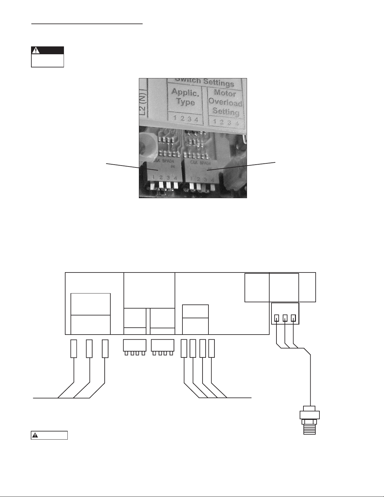
Tension
dangereuse
DANGER
Entrée
1phase
TERRE
L1
L2 (N)
Pour le réglage
du commutateur,
voir le manuel.
Application
Sortie
vers le
1 2 3 4 1 2 3 4
Capteur
de
pression
Entrée (blanc)
+5V (rouge)
Comm. (noir)
T1T2T3
TERRE
Surcharge
du
moteur
Courant de sortie vers le moteur.
Le bon sens de rotation détermine
la disposition des fils par couleur.
Capteur de
pression
9K518
Courant d’entrée (secteur)
provenant du disjoncteur ou
du sectionneur bipolaire
VERT
NOIR
NOIR
VERT
BLANC
ROUGE
NOIR
BLEU
ROUGE
NOIR
8: ILLUSTRATIONS ET TABLES
AVERTISSEMENT
8: ILLUSTRATIONS ET TABLES
Réglage des commutateurs d'application et de surcharge du moteur
Quand le contrôleur est sous tension, les interrupteurs des commutateurs d’application et de surcharge du
moteur le sont aussi. On doit donc toujours mettre le disjoncteur et le sectionneur hors circuit et attendre
5 min avant de toucher aux interrupteurs.
Réglage du commutateur
d'application
Voir la figure 6 pour le
réglage approprié.
Schéma de câblage de l’Aquavar ABII
Réglage du commutateur de
surcharge du moteur
Voir la figure 6 pour le réglage
approprié.
Figure 3
32
Afin de ne pas endommager le contrôleur ni en annuler la
garantie, ne pas l'alimenter en 230 V s'il est conçu pour 115 V.
Figure 4
Page 33

8: ILLUSTRATIONS ET TABLES
8: ILLUSTRATIONS ET TABLES (suite)
Plaque signalétique type montrant les intensités (A) avec facteur de surcharge
Intensités (A) avec facteur
de surcharge servant au
réglage du commutateur
de surcharge du moteur
Dans le cas illustré, paramétrer l’intensité à 4,2 A suivant la table de réglage de la surcharge du moteur. Cette valeur
tient compte de toutes les uctuations de tension.
Figure 5
Tables apposées à l’intérieur du couvercle du contrôleur
Réglage du commutateur de surcharge du moteur
AVERTISSEMENT
Couper le courant et attendre que la DEL s’éteigne avant de toucher
aux interrupteurs du commutateur de surcharge du moteur.
Interrupteur : sorti = 1, rentré = 0
Interrupteurs du Surcharge paramétrée
commutateur DIP du moteur (A)
1 2 3 4 1AB2 2AB2
1 1 1 1 2,5 4,6
1 1 1 0 2,8 5,2
1 1 0 1 3,3 5,3
1 0 1 1 3,5 5,8
0 1 1 1 3,8 6,5
0 0 0 0 4,2 6,9
Table de réglage du commutateur de surcharge du moteur
Utiliser la table ci-dessus, qui trouve aussi à l’intérieur du couvercle du contrôleur, pour régler le commutateur de surcharge du moteur.
Réglage du commutateur d’application
AVERTISSEMENT
Interrupteurs du commutateur DIP Interrupteur : sorti = 1, rentré = 0
1 2 3 4 Fréquence (vitesse) minimale (Hz) Rampe paramétrée
1 1 1 1* 10 Lente
1 1 1 0* 10 Moyenne
1 1 0 1* 10 Rapide
1 0 1 1 30 Lente
0 1 1 1 30 Moyenne
0 0 0 0 30 Rapide
* NE PAS UTILISER CES PARAMÈTRES AVEC LES POMPES SUBMERSIBLES.
Couper le courant et attendre que la DEL s’éteigne avant de
toucher aux interrupteurs du commutateur d’application.
Figure 6
Table des
codes d’état
du système
Utiliser la table
ci-contre, se
trouvant aussi
à l’intérieur du
couvercle du
contrôleur, pour
diagnostiquer
les anomalies du
système.
Codes d’état du système*
Voyant vert
Fixe Attente ou basse tension
Clignotant Pompe en marche
Voyant rouge
Fixe
1 clignote- Pas d’eau ou
ment désamorçage
2 clignote- Réservoir trop plein
ments
3 clignote- Anomalie liée au
ments capteur de pression
4 clignote- Pompe ou
ments moteur bloqués
5 clignote- Court-circuit
ments
6 clignote- Défaut de mise
ments à la terre
7 clignote- Température élevée
ments
8 clignote- Surtension
ments (> 264 V c.a.)
9 clignote- Surcharge du moteur
ments
* Voyants éteints : tension nulle
Table de réglage du commutateur
d’application
Utiliser la table ci-contre, également située
à l’intérieur du couvercle du contrôleur,
pour régler le commutateur d’application.
Remplacement du contrôleur
ou très basse
33
Page 34

9: DÉPANNAGE
Tension
dangereuse
DANGER
9: DÉPANNAGE
Généralités
L’Aquavar ABII effectue son autodiagnostic. En cas d’anomalie, jeter un coup d’œil au voyant de fonctionnement situé
sur le devant du contrôleur. S’il est éteint, c’est que la tension d’entrée est nulle ou faible (< 50 V).
Le voyant de fonctionnement n’est pas un détecteur de tension ! Il faut mettre le sectionneur et le disjoncteur hors circuit, puis attendre 5 min avant de procéder à l'entretien du contrôleur, qui, autrement, pourrait être parcouru par une tension élevée.
Voir les codes d’état du système (g. 6 et intérieur du couvercle du contrôleur) pour en diagnostiquer les anomalies.
UTILISER LA TABLE CI-APRÈS POUR FACILITER LE DIAGNOSTIC DES ANOMALIES.
VOYANT VERT
Aspect État du système Description
Fixe En attente ou Le voyant vert xe indique l'arrêt de la pompe. Le système est en
tension faible attente lorsqu’il n’y a pas de demande et que la pression de consigne
est atteinte. Le système décèle une tension d'entrée faible quand
celle-ci chute sous 196 V c.a. pour les contrôleurs 1AB2 et 2AB2 et
sous 98 V c.a. pour les contrôleurs 1151AB2.
Clignotant Pompe en marche Le voyant vert clignotant signale que la pompe est en marche. Si
elle ne l’est pas, couper l’alimentation du contrôleur et attendre
5 min. Vérier la liaison électrique entre le moteur et le contrôleur.
VOYANT ROUGE
Fixe Erreur liée au contrôleur Remplacer le contrôleur Aquavar ABII.
1 clignotement Pas d’eau ou La pression du système baisse de 5 lbf/po² et plus sous la pression
désamorçage de consigne, et le courant de sortie chute durant 10 s sous les 75 %
de la valeur réglée pour la surcharge du moteur. Le système
redémarrera automatiquement après 5 min. Si l'anomalie se produit
3 fois en une heure, le système ne redémarrera pas et devra être remis
à l'état initial manuellement. Si le problème persiste, vérier la capacité
de la source d'approvisionnement, le débit de la pompe, le réglage de
la surcharge du moteur et s'il y a obstruction entre la source et la
pompe.
2 clignotements Réservoir trop plein Une chute de pression rapide et importante a eu lieu. La pompe
continuera de fonctionner malgré cet avertissement, qui peut être dû
à une pression d’air trop basse dans le réservoir ou à un défaut de la
membrane de celui-ci, voire à des uctuations de débit excessives.
L’erreur est effacée au redémarrage de la pompe. Vérier la pression
d’air du réservoir si l’erreur se répète souvent, mais mettre d'abord le
contrôleur hors tension pour empêcher le démarrage de la pompe,
puis ouvrir un robinet pour éliminer la pression dans le système.
3 clignotements Anomalie liée au La rétroaction du capteur de pression pose problème. Vérier la
capteur de pression liaison électrique entre le capteur et le contrôleur, mais avant,
mettre ce dernier hors tension et attendre 5 min. Ouvrir le
couvercle du contrôleur et vérier si le capteur est câblé
conformément au schéma (g. 4). S’il l’est, vérier la tension
d’entrée du capteur aux bornes du contrôleur avec un voltmètre
c.c. en connectant le l positif à Entrée (l blanc) et le négatif à
Commun (l noir). Rétablir le courant. La tension devrait se situer
entre 0,5 et 4,5 V c.c. ± 0,2 V c.c. Si elle est hors de ces limites,
remplacer le capteur.
4 clignotements Pompe ou moteur Des débris se sont accumulés dans la pompe, ou bien une panne
bloqués électrique s’est produite dans le moteur. Vérier l’erreur en
mettant le contrôleur hors tension durant 1 min, puis en le
remettant sous tension. Si l’erreur persiste, vérier la pompe.
34
Page 35

9: DÉPANNAGE
135,36
(5,33)
259,08
(10,20)
237,06
(9,33)
12,07
(0,48)
157,90
(6,22)
135,36
(5,33)
135,36
(5,33)
259,08
(10,20)
237,06
(9,33)
12,07
(0,48)
157,90
(6,22)
114,30
(4,50)
57,15
(2,25)
81,28
(3,20)
16,51
(0,65)
9: DÉPANNAGE (suite)
VOYANT ROUGE
Aspect État du système Description
5 clignotements Court-circuit Il peut y avoir eu court-circuit entre phases et entre phase et terre
sur le câblage. Le vérier, mais avant, mettre le contrôleur hors
tension et attendre 5 min. Ouvrir le couvercle du contrôleur et
débrancher les ls à T1, T2 et T3. Mesurer la résistance entre tous
les ls de moteur avec un ohmmètre. Nota : la résistance entre
phases de l’enroulement est généralement de 2 à 10 Ω.
6 clignotements Défaut de mise à la terre Un court-circuit peut s’être produit entre phase et terre sur le
câblage. Le vérier, mais avant, mettre le contrôleur hors tension
et attendre 5 min. Ouvrir le couvercle du contrôleur et débrancher
les ls de moteur à T1, T2, T3 et TERRE (GND). Mesurer la
résistance entre chacun de ces ls et la terre avec un
mégohmmètre réglé à 500 V c.c. Une résistance inférieure à
500 000 Ω ou à 0,5 MΩ est l’indice d’un moteur défectueux.
7 clignotements Température élevée La température interne du contrôleur est élevée. Si elle atteint
70 ºC (158 ºF), le contrôleur s’arrêtera jusqu’à ce que la
température baisse à 65,5 ºC (150 ºF). Ne pas exposer le
contrôleur à la lumière du soleil ni à une température ambiante
dépassant 40 ºC (104 ºF).
8 clignotements Surtension Fixer les ls positif et négatif d'un voltmètre c.a. sur les bornes L1 et
L2 du contrôleur ABII et mesurer la tension d'entrée. S'assurer qu'elle
n'excède pas 264 V c.a. pour les contrôleurs 1AB2 et 2AB2 ni
132 V c.a. pour les contrôleurs 1151AB2.
9 clignotements Surcharge du moteur Le courant d’alimentation du moteur dépasse la surcharge
paramétrée pour celui-ci (g. 3, 5 et 6). S’assurer du bon réglage
du commutateur de surcharge du moteur suivant les directives de
la section 7. Si le réglage est correct, vérier le moteur.
10: DIMENSIONS DU CONTRÔLEUR
10: DIMENSIONS DU CONTRÔLEUR
Les dimensions ci-dessous sont en millimètres (et en pouces).
8,38
(0,33)
242,04
(9,53)
232,56
(9,16)
57,15
(2,25)
114,30
(4,50)
81,28
(3,20)
16,51
(0,65)
259,08
(10,20)
12,07
(0,48)
237,06
(9,33)
135,36
(5,33)
99,06
(3,90)
157,90
(6,22)
35
Page 36

GARANTIE LIMITÉE
La présente garantie applique à ce Xylem Inc. le produit.
Toute pièce se révélant défectueuse sera remplacée sans frais pour le détaillant durant la période de garantie suivante expirant la première : vingt-quatre (24) mois à compter de la date
d’installation ou trente (30) mois à partir de la date de fabrication.
Le détaillant qui, aux termes de la présente garantie, désire effectuer une demande de règlement doit s’adresser au distributeur Xylem Inc. agréé chez lequel la matériel a été achetée
et fournir tous les détails à l’appui de sa demande. Le distributeur est autorisé à régler toute demande par le biais du service à la clientèle de Xylem Inc.
La garantie ne couvre pas :
a) les frais de main-d’œuvre ni de transport ni les frais connexes encourus par le détaillant ;
b) les frais de réinstallation du matériel réparé ;
c) les frais de réinstallation du matériel de remplacement ;
d) les dommages indirects de quelque nature que ce soit ;
e) ni les pertes découlant de la panne.
Aux fins de la garantie, les termes ci-dessous sont définis comme suit :
1) « Distributeur » signie une personne, une société de personnes, une société de capitaux, une association ou autre entité juridique servant d'intermédiaire entre Xylem Inc. et le
détaillant pour les achats, les consignations ou les contrats de vente des matériel en question.
2) « Détaillant » veut dire une personne, une société de personnes, une société de capitaux, une association ou autre entité juridique dont les activités commerciales sont la vente ou la
location de matériel à des clients.
3) « Client » désigne une entité qui achète ou loue les matériel en question chez un détaillant. Le « client » peut être une personne, une société de personnes, une société de capitaux,
une société à responsabilité limitée, une association ou autre entité juridique se livrant à quelque activité que ce soit.
LA PRÉSENTE GARANTIE SE RAPPORTE AU DÉTAILLANT SEULEMENT.
Xylem, Inc.
2881 East Bayard Street Ext., Suite A
Seneca Falls, NY 13148
Téléphone: (800) 453-6777
Télécopie: (888) 322-5877
www.centripro.com
CentriPro et Aquavar ABII sont des marques déposées de Xylem Inc. ou d'une de ses filiales.
© 2012, Xylem Inc. IM156 Révision numéro 6 Février 2013
 Loading...