

Page 1
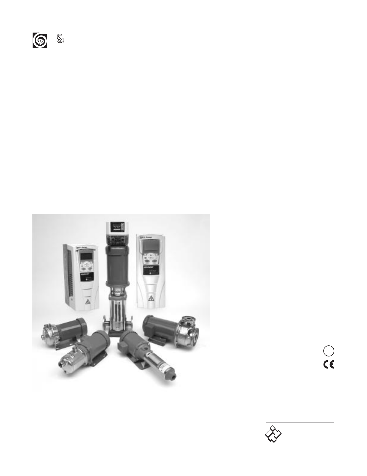
Variable Speed
Pump Control
New Sizes Addendum*
(August 2004)
Models covered:
04168321 - 2 HP - single phase, 230V
04168331 - 3 HP - single phase, 230V
04169131 - 5 HP - single/three phase, 230V*
04169141 - 7
1
⁄
2 HP - single/three phase, 230V*
04169181 - 10 HP - single phase, 230V*
04169151 - 10 HP - three phase, 230V*
04168371 - 5 HP - three phase, 460V
04168491 - 7
1
⁄2 HP - three phase, 460V
04168501 - 10 HP - three phase, 460V
AQUAVAR
®
G L Pumps
IM154R01
U
®
L
Goulds Pumps
ITT Industries
Page 2
AQUAVAR Controller Technical Data:
AQUAVAR Controller Motor Supply Voltage Recommended
Part Nos. Rated Output Voltage Current 40-60 Hz Circuit Protection
(1)
04168321 2 HP 3 ph 230V 7A
Single Phase
15 Ampere
240 VAC ± 10%
04168331 3 HP 3 ph 230V 10A
Single Phase
15 Ampere
240 VAC ± 10%
04168371 5 HP 3 ph 460V 9A
Three Phase
15 Ampere
380-460 VAC ± 15%
04168491 71⁄2HP 3 ph 460V 131⁄2A
Three Phase
20 Ampere
380-460 VAC ± 15%
04168501 10 HP 3 ph 460V 17A
Three Phase
25 Ampere
380-460 VAC ± 15%
AQUAVARController
(2) Motor Circuit Protection Circuit Protection
Part Rated
Supply V oltage
Input
Input V oltage Current
Single Phase Three Phase
Number Output Frequency INPUT (1) INPUT (1)
(HP) 40-60 Hz (Hz) Phase (V) (A) Fuse Size (A) Fuse Size (A)
04169131 5 220-240 VAC +/- 15% 48....62 1 or 3 ph 3 ph 230V 15 40 20
04169141 71/
2 220-240V AC +/- 15% 48....63 1 or 3 ph 3 ph 230V 22 60 30
04169181 10 220-240VAC +/- 15% 48....64 1ph only 3 ph 230V 28 70 NA
04169151 10 220-240VAC +/- 15% 48....64 3ph only 3 ph 230V 28 NA 40
NOTE: (1) Recommended short circuit protection is UL Type T, very fast acting fuses.
(2) Dimensions are similiar to the 5, 71/
2 and 10 HP, 3 phase, 460 Volt units.
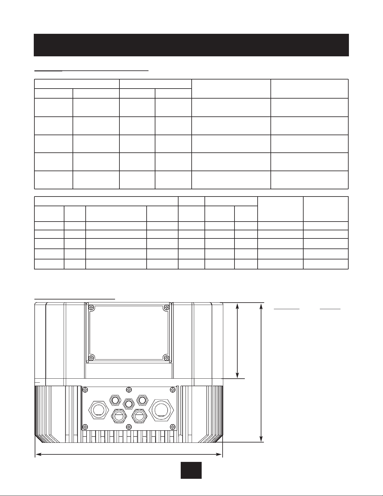
Dimensions and Weights
Part Nos. Weight
04168321 12 lbs.
04168331 12 lbs.
04168371 12 lbs.
04168491 22 lbs.
04168501 22 lbs.
For other technical data,
see Appendix B
of IM043R07.
NOTE: All motors must be
at least 3 phase, TEFC,
Class B design.
AQUAVAR
Ø195 (2–5 HP)
Ø280 (7
1
⁄2–10 HP)
100
185
* Dimensions are in mm.
1 inch = 25.4 mm
1
Page 3

2
AQUAVAR
Electrical Connections (Line Reactors)
Input Line Requirements
Line Voltage
See the Power and Current Ratings table for the allowable fluctuation of AC line voltage for your
particular model. A supply voltage above or below the limits given in the table will cause the
drive to trip with either an overvoltage or under voltage fault.
To verif y power quality, consult your local power utility for a chart recorder.
Exercise caution when applying the AQUAVAR controller on low-line conditions.
For example, and AQUAVAR controller will operate properly on a 208 Vac line – but the maximum
output voltage will be limited to 208 Vac. Now if a motor rated for 230 Vac line voltage is
controlled by this drive, higher motor currents and increased heating will result.
Therefore, ensure that the voltage rating of the motor matches the applied line voltage.
Use of Isolation Transformers and Line Reactors
The AQUAVAR controller is is per fectly suitable in most cases for direct connection to a power source
as specified in this manual and the technical nameplate affixed to the unit. There are however a
few cases where a properly sized isolation transformer
or line reactor should be employed to
minimize the risk of drive malfunction, damage or nuisance tripping:
• As noted in
Table 7
, transformer sizing, when line capacity is greater than 10 times the KVA
rating of the drive. Consult the factory for assistance in sizing the line reactor.
• When power factor correction capacitors are employed on the drive’s power source.
• When the power source is known to be subject to transient power interruptions or
significant voltage spikes.
• When the power source supplying the drive also supplies large devices such as DC drives
that contain controller rectifiers.
• When power quality or known transient voltage spikes is suspected or questioned.
Table 7: Transformer Sizing for the AQUAVAR Controller
Controller HP 1 2 3 5 7.5 10 15 20 25 30 40 50 60 75
Transformer kVA 2 4 5 9 13 18 23 28 36 42 56 70 90 112
* Consult factory for more information, if needed.
Page 4

3
AQUAVAR
Mounting P
rocedure
Components Included
(4) Screw M 5 x 60 (1) Thermal Resistor Cable Gland (4) Motor Mounting Clamp
Mounting
Gasket
4 screws
M5x50
Center bit
Transducer
Display
changeable
to 180º
Connection
motor
conduit box
Thermistor
4 mounting
clamps
Mounting:
• Remove the 3 screws from the
AQUAVAR cover.
• Place the center bit in the
AQUAVAR heat sink.
• Place the AQUAVAR on the motor.
• Hang the 4 clamps by the heat
sink and mount with the 4 screws.
• Mount the cover with the
3 screws (remember to use the
gaskets).
• Depending on pump orientation,
the display can be rotated 180º.
Page 5

4
AQUAVAR
Wiring P
rocedure
– Single Phase Connections (2, 3, 5, 71⁄2 and 10 HP)
– Three Phase Connections (5, 7
1
⁄2,10 and 15 HP)
AQUAVAR
®
AQUAVAR
®
RS485 Interface
Control Terminals
RS485 Interface
Control Terminals
Power Supply Motor Connection
1x230 VAC 3 Phase Out
L=L
1
, N=L
2
U V W
Power Supply Motor Connection
3x400 VAC 3 Phase Out
L
1
, L2,L
3
U V W
Page 6

5
AQUAVAR
Pin Connection
(to display)
40 Pin Connection
(to power board)
DIP - Switch
SW 4
24VDC Output
(max. 800mA)
for External Fan
RS485
Terminals
Motor ConnectionControl Terminal BlockMain Supply
Main P
arts of the Control Board (PN# 2509641)
Dip-Switch on the Controller Board
SW4: DIP-Switch to Select the Switching Frequency
Before switching, disconnect the power supply, otherwise
the AQUAVAR could be destroyed.
SW 4 Switching Frequency
12
OFF OFF 8 kHz (Standard)
ON OFF 5 kHz
OFF ON 4 kHz
ON ON 2.5 kHz* *Recommended for submersible motors.
NOTE
Lower switching frequencies reduce heat in motor,
but increase audible noise.
For complete wiring procedures, refer to page 18 of IM043R07.
For complete programming procedures, refer to page 26 of IM043R07.
SW 4
2
1
8
ATTENTION
Page 7

6
AQUAVAR
F
ront Plate
The diagram below shows the location of the programming keys and displays on the new
AQUAVAR models. Use this illustration with the programming steps in IM043R07.
nd
2
I
+
ON
RUNPOWER
AQUAVAR
Power
Run
FAULT
®
0
Sch 60.25
OFF
Select
*
Fault
Page 8

G L Pumps
©2004 ITT Water Technology, Inc.
September, 2004 1 Goulds Drive
Printed in U.S.A. Auburn, NY 13021
AQUAVAR LIMITED WARRANTY
This warranty applies to all new style AQUAVAR controllers referenced on the front of this booklet.
Any part or parts found to be defective within the warranty period shall be replaced at no charge to the distributor during the warranty period. The warranty period shall exist for a period of twenty four (24) months from
date of installation or thirty (30) months from date of manufacture, whichever period is shorter.
A dealer who believes that a warranty claim exists must contact the authorized Goulds Pumps distributor from
whom the AQUAVAR was purchased and furnish complete details regarding the claim. The distributor is authorized to adjust any warranty claims utilizing the Goulds Pumps Customer Service Department.
The warranty excludes:
(a) Labor, transportation and related costs incurred by the dealer;
(b) Reinstallation costs of repaired equipment;
(c) Reinstallation costs of replacement equipment;
(d) Consequential damages of any kind; and,
(e) Reimbursement for loss caused by interruption of service.
For purposes of this warranty, the following terms have these definitions:
(1) "Distributor" means any individual, partnership, corporation, association, or other legal relationship that
stands between Goulds Pumps and the dealer in purchases, consignments or contracts for sale of the
subject pumps.
(2) "Dealer" means any individual, partnership, corporation, association or other legal relationship which
engages in the business of selling or leasing pumps to customers.
(3) "Customer" means any entity who buys or leases the subject AQUAVAR from a dealer. The "customer" may
mean an individual, partnership, corporation, limited liability company, association or other legal entity
which may engage in any type of business.
THIS WARRANTY EXTENDS TO THE DEALER ONLY.
Goulds Pumps is a brand of ITT Water Technology, Inc. a subsidiary of ITT Industries, Inc.
AQUAVAR, G&L Pumps and Goulds Pumps and
the ITT Engineered Blocks Symbol are registered
trademarks and tradenames of ITT Industries.
www.goulds.com
Goulds Pumps
ITT Industries
 Loading...