

Page 1
RED JACKET
Water Products
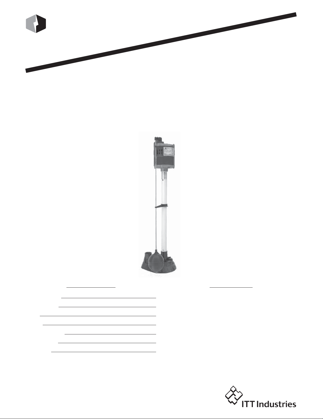
Sump Pump
Sump Pump
Installation and Operation Manual
®
Vertical
Vertical
Model Number:
Serial Number:
Code:
Dealer:
Dealer Phone No.
Purchase Date:
Installation:
IM152R00
Owner’s Information
Owner’s Information
SUBJECT PAGE
General Information ...................................................... 2
Sump Pit........................................................................ 2
Installation .................................................................... 2
Troubleshooting ............................................................. 3
Maintenance .................................................................. 3
Red Jacket Water Products Limited Warranty .................. 4
www.redjacketwaterproducts.com
Table of Contents
Table of Contents
Page 2
General Information
General Information
• Before installation, read the following instructions
carefully. Each pump is individually factory tested to
assure proper performance. By closely following these
instructions, potential operating problems should be
eliminated, providing years of trouble-free service.
WARN ING
Hazardous
voltage
RISK OF ELECTRIC SHOCK. Always
disconnect the pump from the power
source before handling or making adjustments.
• Always wear rubber boots when water is on the floor and
you must unplug the pump. Make sure the pump power
source is a separately fused, grounded 3-wire type
receptacle of 15 amp capacity. DO NOT REMOVE
GROUND PRONG OR PLUG. DO NOT USE AN
EXTENSION CORD. Check to make sure installation is
in accordance with the National Electric code and all
applicable local codes.
• Tools required for installation are a) pipe wrench, b)
regular screw driver, and c) hacksaw (for replacement or
removal of existing rigid piping.)
• DO NOT use pumps in water over 140° F.
• DO NOT drain hot water heaters into the sump pit
when servicing.
• DO NOT use pumps in mud, sand, cement, oil or
chemicals
• DO NOT modify the pumps in any way.
Sump Pit
Sump Pit
2. *SEE NOTE BELOW. Set the new pump in place
making sure the float switch has adequate clearance and
will not hang-up on the pit wall.
1
⁄4" threaded discharge is provided on the pump for
3. A 1
connection to the discharge pipe. Do not reduce the
discharge size to below 1
1
⁄4" as this will affect pump flow
and performance. Schedule 40 PVC pipe is recommended; however, flexible discharge hose kits may be
used for temporary installations.
4. Connect the pipe or the discharge hose to the discharge
of the pump. HAND TIGHTEN ONLY. Overtightening
may cause the pump housing to crack.
5. Install a union or other means of separating the discharge pipe just above the floor to facilitate removal of
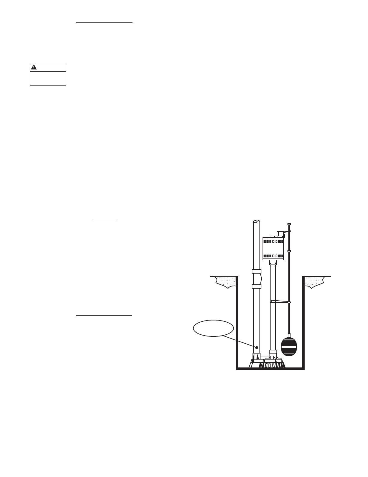
the pump if necessary. A check valve is recommended
just above or in place of the union to prevent the
backflow of water after each pump cycle.
If a check valve is used, a 1⁄8" air bleed hole should be
drilled in the discharge pipe just above the pump’s
discharge outlet to prevent pump “airlock”. See
Figure A. A small spray of water out of this hole is
normal while pump is running.
6. Connect additional pipe as necessary to direct the
discharge to the desired location. Discharge should be
kept as short as possible with a minimum number of
turns. Check all connections for leaks.
11⁄4" DISCHARGE
1. A sump pit not less than 14" in diameter is
recommended. A larger diameter pit is preferred as it
allows for a longer pumping cycle and reduced switch
cycling.
2. If the pit is not already enclosed on the bottom, provide
a hard level bottom of bricks or concrete. DO NOT
place the pump directly on earth, gravel or debris since
this can cause excessive wear of the impeller and possible
jamming. Remove all debris from the bottom of the
sump pit before installation of the pump. A sump pit
cover is suggested for safety and to prevent foreign
objects from entering the pit.
Installation of Pump
Installation of Pump
1. Removal of old pump:
NOTE: DISCONNECT PUMP FROM POWER
SOURCE BEFORE HANDLING.
Separate the discharge pipe at either the check valve or at
the union. If neither a check valve or union is part of the
existing discharge pipe, cut the pipe just above floor level
with a hacksaw and remove the pump. (A union or check
valve will need to be installed at this cut.)
1
⁄8" AIR-BLEED HOLE
Figure A
*NOTE: Pedestal pumps require assembly of the float, rod
and guide. Snap the plastic rod guide into its position with
its pin located in the center hole on the column of the
pump. Insert the threaded end of the float rod down
through the hole in the guide and attach the float ball to
the threaded end. Remove the upper rubber stop and insert
the rod through the hole in the switch arm. Replace the
upper rubber stop at least 1⁄2" from the end of the rod.
2
Page 3
Tr oubleshooting
Troubleshooting
WARN ING
Hazardous
voltage
This guide is designed to help identify reasons for potential
operating problems. It is not a service guide.
DISMANTLING OF PUMP VOIDS WARRANTY.
Servicing of pump other than simple cleaning of pump inlet
or impeller should be referred to the factory or its authorized service centers.
NOTE: The manufacturer assumes no responsibility for
PUMP DOES NOT RUN OR HUM:
1) Line circuit breaker may be off, tripped or loose. Have
a certified electrician check fuse or breaker.
2) Water level in pit may be too low to activate switch.
Add more water to pit.
3) Plug on power cord may not be making contact in
receptacle. Check security and connection.
4) Float may be obstructed. Make sure float is free and not
interfering with the pit wall or other obstruction.
5) If all symptoms check OK, the motor winding may be
open. Consult factory.
PUMP RUNS OR HUMS BUT DOES NOT DELIVER
WATER:
1) Check valve may be installed backwards or is defective.
Check to make sure it is installed properly and flapper
in valve is free to move.
2) Discharge line may be blocked or frozen. Check to see
if line passes through cold areas or is blocked.
3) Pump may be air-locked. Make sure air bleed hole was
drilled in discharge pipe. See Figure A for proper
location of bleed hole.
4) Vertical lift is beyond pump’s capability. Pump’s
maximum lift capability is 17'.
NOTE: At the pump’s maximum lift there will be
5) Inlet screen of pump is plugged or the impeller is
jammed. Remove the pump screen and clean inlet and
impeller.
PUMP RUNS AND REMOVES WATER BUT DOES
NOT SHUT OFF:
1) Float is stuck in the “ON” position. Check to make
sure the float is free to move up and down without
obstruction.
2) Switch is defective. Consult factory.
PUMP RUNS BUT DELIVERS VERY LITTLE WATER.
1) Vertical lift is approaching the pump’s maximum lift
capability. Refer to the above maximum lift chart.
2) Pump’s inlet is partially blocked. Check to make sure
the inlet is clear of debris.
3) Discharge line is partially blocked. Check for blockage.
4) Check valve is not opening all the way. Check for
defective or blocked check valve.
ALWAYS DISCONNECT THE PUMP
FROM POWER SOURCE BEFORE
HANDLING.
damage or injury due to disassembly.
no flow.
CIRCUIT BREAKER TRIPS OR FUSE BLOWS WHEN
PUMP STARTS
1) Fuse or breaker size is too small. A 15 amp breaker
should be used.
2) Other major appliances are on the same circuit. Pump
should be on its own circuit.
3) Pump is connected to an extension cord or wiring is
inadequate. Have an electrician check for proper
wiring.
4) Defective motor or switch. Consult factory.
Maintenance
Maintenance
• Pedestal sump pump have open, exposed motors. Take
precautions to make sure the motor does not get wet
from dripping pipes, etc.
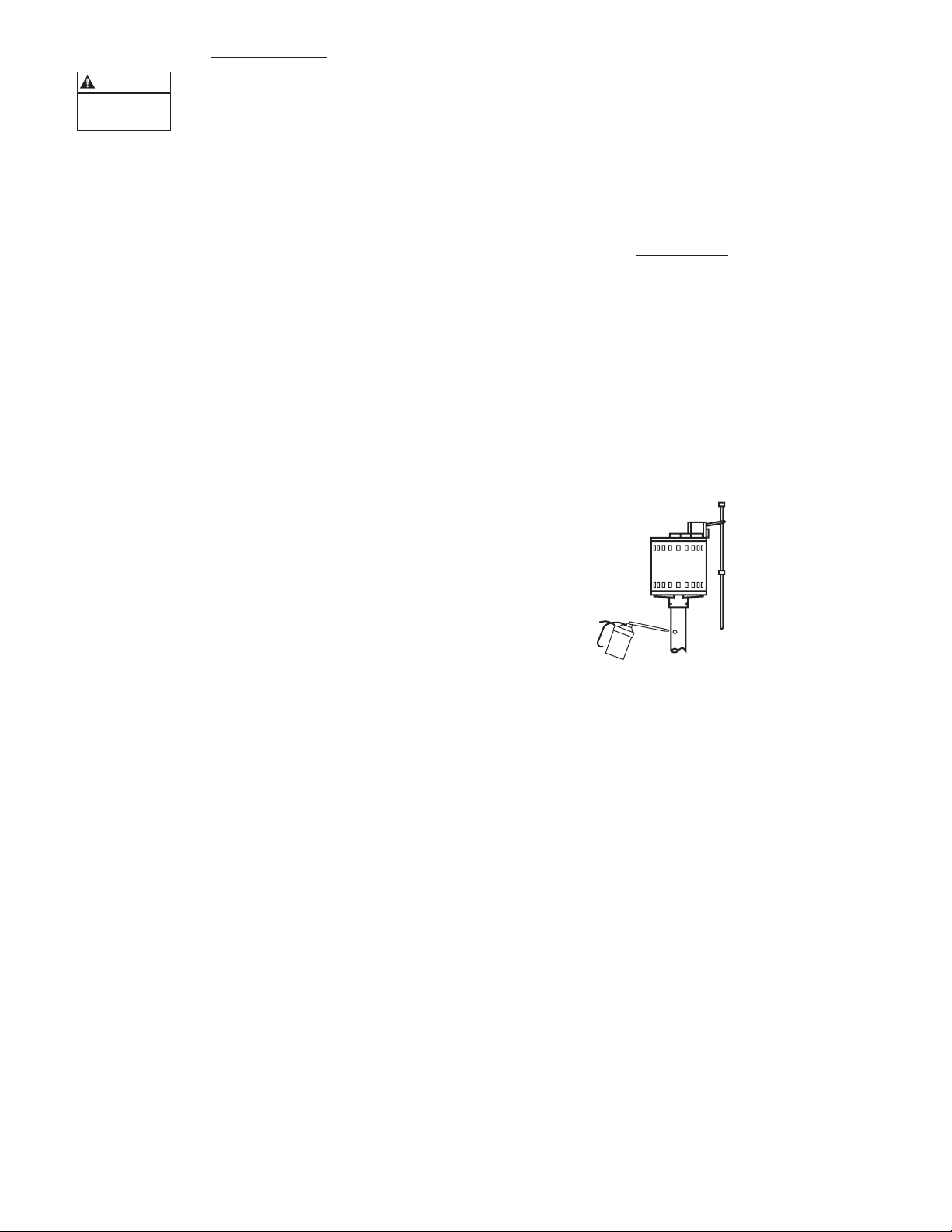
• Pour an ounce of 20 or 30 weight oil into the hole near
the top of the pedestal column every 6 months. A label
next to the hole designates where to add the oil. See
Figure B.
• Pour enough water into the sump pit to activate the
pump periodically when not normally in use.
• Check periodically to make sure the pit is free from
accumulated debris, rocks or other objects that may
potentially jam the pump.
Figure B
3
Page 4

RED JACKET
Water Products
®
This warranty applies to all water systems pumps manufactured by Red Jacket Water Products.
Any part or parts found to be defective within the warranty period shall be replaced at no charge to the dealer during the warranty period. The warranty period shall
exist for a period of twelve (12) months from date of installation or eighteen (18) months from date of manufacture, whichever period is shorter.
Red Jacket Water Products (the manufacturer) warrants to the original end-user Purchaser of each of the Manufacturer’s Red Jacket Waterbear, Grizzly and Enduro
submersible pumps that any part thereof which proves to be defective in material or workmanship within 36 months from manufacture date will be replaced at no
charge with a new or re-manufactured part, F.O.B. factory. In the case of the Big-Flo submersible pump and motor unit and all jet and centrifugal pumps, however, the
warranty period shall be the earlier of 24 months from the date of manufacture or 12 months from the date of installation.
A dealer who believes that a warranty claim exists must contact the authorized Red Jacket Water Products distributor from whom the pump was purchased and furnish
complete details regarding the claim. The distributor is authorized to adjust any warranty claims utilizing the Red Jacket Water Products Customer Service Department.
The warranty excludes:
(a) Labor, transportation and related costs incurred by the dealer;
(b) Reinstallation costs of repaired equipment;
(c) Reinstallation costs of replacement equipment;
(d) Consequential damages of any kind; and,
(e) Reimbursement for loss caused by interruption of service.
For purposes of this warranty, the following terms have these definitions:
(1) “Distributor” means any individual, partnership, corporation, association, or other legal relationship that stands between Red Jacket Water Products and the dealer
in purchases, consignments or contracts for sale of the subject pumps.
(2) “Dealer” means any individual, partnership, corporation, association, or other legal relationship which engages in the business of selling or leasing pumps to
customers.
(3) “Customer” means any entity who buys or leases the subject pumps from a dealer. The “customer” may mean an individual, partnership, corporation, limited
liability company, association or other legal entity which may engage in any type of business.
THIS WARRANTY EXTENDS TO THE DEALER ONLY.
Red Jacket Water Products is a licensed trademark.
The ITT Engineered Blocks symbol is a registered
trademark and tradename of ITT Industries.
Red Jacket Water Products reserves the right to make design improve-
ments and pricing modifications as necessary and without notice.
©2002 Red Jacket Water Products
Printed in U.S.A.
RED JACKET WATER PRODUCTS LIMITED WARRANTY
Page 5

®
RED JACKET
Water Products
Vertical
Vertical
Sump Pump
Sump Pump
Manual de instalación y funcionamiento
Información del propietario
Información del propietario
Número de Modelo:
Número de Serie:
Código:
Agente:
No. telefónico del agente:
Fecha de compra:
Fecha de instalación:
Índice
Índice
TEMA PÁGINA
Información general ....................................................... 6
Fosa del sumidero .......................................................... 6
Instalación ..................................................................... 6
Identificación de fallas .................................................... 7
Maintenimiento ............................................................. 7
Garantía limitada de Red Jacket Water Products .............. 8
Page 6

Información general
Información general
Instalación de la bomba
Instalación de la bomba
• Lea las siguientes instrucciones cuidadosamente antes de
la instalación. Cada bomba es sometida a prueba
individualmente en la fábrica para verificar el
rendimiento apropiado. Siguiendo estas instrucciones en
forma cercana se eliminarán los posibles problemas de
operación, ofreciendo años de servicio sin averías.
ADVERTENCIA
Tensión
peligrosa
RIESGO DE ELECTROCHOQUE.
Siempre desconecte la bomba de la fuente
de energía antes de manejarla o hacer
ajustes.
• Siempre use botas de goma cuando haya agua en el piso y
deba desenchufar la bomba. Asegúrese de que la fuente
de energía de la bomba tenga un tomacorriente trifilar de
15 amperios de capacidad, conectado a tierra y con
fusible separado. NO QUITE EL ENCHUFE O CLAVIJA
DE CONEXIÓN A TIERRA. NO USE UN CABLE DE
EXTENSIÓN. Inspeccione para asegurar que la
instalación sea de acuerdo con el Código Eléctrico de los
Estados Unidos y todos los códigos locales
correspondientes.
• Las herramientas requeridas para instalación son a) llave
para tubos, b)destornillador regular y c) sierra para
metales (para reemplazar o retirar tuberías rígidas
existentes).
• NO use bombas en agua a una temperatura superior a los
140 ºF.
• NO drene los calentadores de agua caliente en la fosa del
sumidero cuando les esté dando servicio.
• NO use las bombas en lodo, arena, cemento, aceite o
productos químicos
• NO modifique las bombas de ninguna manera.
1. Retiro de la bomba vieja.
NOTA: DESCONECTE LA BOMBA DE LA FUENTE
DE ENERGÍA ANTES DE MANEJARLA.
Separe la tubería de descarga ya sea en la válvula de
retención o en la unión. Si la tubería de descarga
existente no incluye ni una válvula de retención ni una
unión, corte la tubería justo arriba del nivel del piso con
una sierra para metales y retire la bomba. (Deberá
instalarse una unión o válvula de retención en este corte.)
2. *VER LA NOTA ABAJO. Coloque la bomba nueva en
posición, asegurándose de que el interruptor de flotador
tenga espacio adecuado y que no cuelgue de la pared de
la fosa.
3. Se incluye una descarga roscada de 11⁄4 pulg. en la bomba
para conectarla a la tubería de descarga. No reduzca el
tamaño de la descarga a menos de 11⁄4 pulg. ya que esto
afectará el flujo y rendimiento de la bomba. Se
recomienda una tubería de PVC (cloruro de polivinilo)
de especificación 40; sin embargo, se pueden usar juegos
de manguera de descarga flexible para instalaciones
temporales.
4. Conecte la tubería o la manguera de descarga a la
descarga de la bomba. APRIETE CON LA MANO
ÚNICAMENTE. El apriete excesivo puede agrietar la
caja de la bomba.
11⁄4" DESCARGA
Fosa de sumidero
Fosa de sumidero
1. Se recomienda una fosa de sumidero de no menos de
14 pulg. de diámetro. Se prefiere una fosa de diámetro
grande ya que permite un ciclo de bombeo más largo y
un ciclo de conmutación reducido.
2. Si la bomba aún no está cubierta sobre el fondo,
proporcione un fondo nivelado duro de ladrillos o
concreto. NO coloque la bomba directamente sobre el
suelo, grava o residuos ya que esto puede producir
desgaste excesivo del impulsor y un posible
atascamiento. Retire todos los residuos del fondo de la
fosa de sumidero antes e instalar la bomba. Se sugiere
instalar una tapa en la fosa de sumidero para mayor
seguridad y para impedir la entrada de objetos extraños a
la fosa.
AGUJERO DE PURGA
DE AIRE DE 1⁄8 PULG.
Figura A
*NOTA: En las bombas de pedestal es necesario armar
el flotador, la varilla y la guía. Encaje a presión la guía
de la varilla de plástico a su posición, con su pasador
situado en el agujero central en la columna de la bomba.
Inserte el extremo roscado de la varilla de flotador hacia
abajo por el agujero en la guía y conecte la bola del flotador
al extremo roscado. Retire el tope de goma superior e
inserte la varilla por el agujero en el brazo del interruptor.
Reinstale el tope de goma superior al menos a 1⁄2 pulg. del
extremo de la varilla.
6
Page 7

5. Instale una unión u otro medio para separar la tubería de
descarga justo arriba del piso para facilitar el retiro de
la bomba si es necesario. Se recomienda instalar una
válvula de retención justo arriba o en lugar de la unión
para impedir el contraflujo de agua después de cada ciclo
de la bomba.
Si se usa una válvula de retención, debe taladrase un
agujero de purga de aire de
1
⁄8 pulg. en la tubería de
descarga justo arriba de la salida de descarga de la bomba
para impedir el bloqueo con aire. Ver la Figura B.
Es normal que mientras la bomba esté funcionando salga
un pequeño rociado de agua de este agujero.
6. Conecte tubería adicional, según sea necesario, para
dirigir la descarga al lugar deseado. La descarga debe
mantenerse lo más corta posible, con un número mínimo
de vueltas. Revise todas las conexiones para detectar
fugas.
Mantenimiento e identificación de fallas
Mantenimiento e identificación de fallas
ADVERTENCIA
Tensión
peligrosa
SIEMPRE DESCONECTE LA BOMBA
DE LA FUENTE DE ENERGÍA ANTES
DE MANEJARLA.
Esta guía está diseñada para ayudar a identificar las razones
de posibles problemas de operación. No es una guía de
servicio. SI SE DESMANTELA LA BOMBA, SE ANULA
LA GARANTÍA. Excepto por una simple limpieza de la
entrada o el impulsor de la bomba, el servicio de la bomba
debe ser realizado en la fábrica o centros de servicio
autorizados.
NOTA: El fabricante no asume ninguna responsabilidad
por daños o lesiones debido al desmontaje.
LA BOMBA NO FUNCIONA O TIENE UN
ZUMBIDO:
1) El cortacircuitos de línea puede estar desconectado,
disparado o suelto. Solicite a un electricista certificado
que revise el fusible o el cortacircuitos.
2) El nivel de agua en la fosa podría ser demasiado bajo
para activar el interruptor. Agregue más agua a la fosa.
3) Enchufe del cable de alimentación podría no estar
haciendo contacto en el tomacorriente. Verifique la
seguridad y la conexión.
4) El flotador podría estar obstruido. Asegúrese de que el
flotador esté libre y que no interfiera con la pared de la
fosa u otra obstrucción.
5) Si todo lo demás funciona bien, el devanado del motor
podría estar abierto. Consulte con la fábrica.
LA BOMBA FUNCIONA O HACE UN ZUMBIDO,
PERO NO ENTREGA AGUA:
1) La válvula de retención podría estar instalada al revés o
está defectuosa. Revise para verificar que esté instalada
correctamente y que la chapaleta en la válvula puede
moverse libremente.
2) La línea de descarga podría estar bloqueada o
congelada. Inspeccione para ver si la línea pasa por
áreas frías o si está bloqueada.
3) La bomba podría estar bloqueada con aire. Asegure que
se haya taladrado un agujero de purga de aire en la
tubería de descarga. Consulte La Figura A acerca de
la ubicación apropiada del agujero de purga.
4) La elevación vertical está fuera de la capacidad de la
bomba. La capacidad de elevación máxima de la bomba
está 17 pies.
NOTA: No habrá flujo a la elevación máxima de la bomba.
5) El filtro de entrada de la bomba está tapado o el
impulsor está atascado. Retire el filtro de la bomba y
limpie la entrada y el impulsor.
LA BOMBA FUNCIONA Y EXTRAE AGUA, PERO NO
SE PARA:
1) El flotador está atascado en la posición de
“ENCENDIDO”. Inspeccione para asegurar que el
flotador pueda moverse libremente hacia arriba y abajo
sin obstrucción.
2) El interruptor está defectuoso. Consulte con la fábrica.
LA BOMBA FUNCIONA, PERO ENTREGA MUY
POCA AGUA.
1) La elevación vertical se está aproximando a la capacidad
de elevación máxima de la bomba. Consulte la tabla de
elevación máxima anterior.
2) La entrada de la bomba está parcialmente bloqueada.
Inspeccione para asegurar que la entrada esté libre de
residuos.
3) La línea de descarga está parcialmente bloqueada.
Inspeccione para localizar el bloqueo.
4) Determine si la válvula no se está abriendo por
completo. Revise para determinar si la válvula de
retención está defectuosa o bloqueada.
EL CORTACIRCUITOS SE DISPARA O EL FUSIBLE
SALTA CUANDO ARRANCA LA BOMBA
1) El fusible o el cortacircuitos es demasiado pequeño.
Debe usarse un cortacircuitos de 15 amperios.
2) Hay otros artefactos mayores conectados al mismo
circuito. La bomba debe tener su propio circuito.
3) La bomba está conectada a un cable de extensión o
el cableado es inadecuado. Solicite que un electricista
verifique el cableado apropiado.
4) Motor defectuoso en el interruptor. Consulte con
la fábrica.
Mantenimiento
Mantenimiento
• Las bombas tipo pedestal para sumidero tienen motores
abiertos y expuestos. Tome precauciones para asegurar
que los goteos de las tuberías no mojen el motor, etc.
• Vierta una onza de aceite de 20 ó 30 de peso en el
agujero cerca del extremo superior de la columna del
pedestal cada 6 meses. Una etiqueta adyacente al agujero
indica dónde agregar el aceite. Ver la figura B.
• Vierta suficiente agua en la fosa de sumidero para activar
la bomba periódicamente cuando no esté normalmente
en uso.
• Inspeccione periódicamente para asegurar que la fosa esté
libre de residuos acumulados, rocas u otros objetos que
pudiesen atascar la bomba.
Figura B
7
Page 8

RED JACKET
Water Products
®
GARANTÍA LIMITADA DE RED JACKET WATER PRODUCTS
Esta garantía es aplicable a todas las bombas para sistemas de agua fabricadas por Red Jacket Water Products.
Toda parte o partes que resulten defectuosas dentro del período de garantía serán reemplazadas sin cargo para el comerciante durante dicho período de garantía. Tal
período de garantía se extiende por doce (12) meses a partir de la fecha de instalación, o dieciocho (18) meses a partir de la fecha de fabricación, cualquiera se cumpla
primero.
Red Jacket Water Products (el fabricante) garantiza al comprador – usuario final original de cada una de las bombas sumergibles Red Jacket Waterbear, Grizzly y Enduro
del fabricante que cualquier pieza de las mismas que resulte defectuosa en cuanto a material o mano de obra durante el período de 36 meses a partir de la fecha de
fabricación será reemplazada sin cargo con una pieza nueva o reacondicionada, L.A.B. fábrica. Sin embargo, en el caso de la bomba sumergible y motor Big-Flo y todas
las bombas de inyección y centrífugas, el período de garantía será de 24 meses a partir de la fecha de fabricación o 12 meses a partir de la fecha de instalación, según lo
que ocurra primero.
Todo comerciante que considere que existe lugar a un reclamo de garantía deberá ponerse en contacto con el distribuidor autorizado de Red Jacket Water Products del
cual adquiriera la bomba, y ofrecer información detallada con respecto al reclamo. El distribuidor está autorizado a liquidar todos los reclamos por garantía a través del
Departamento de Servicios a Clientes de Red Jacket Water Products.
La presente garantía excluye:
(a) La mano de obra, el transporte y los costos relacionados en los que incurra el comerciante;
(b) los costos de reinstalación del equipo reparado;
(c) los costos de reinstalación del equipo reemplazado;
(d) daños emergentes de cualquier naturaleza; y
(e) el reembolso de cualquier pérdida causada por la interrupción del servicio.
A los fines de esta garantía, los términos “Distribuidor”, “Comerciante” y “Cliente” se definen como sigue:
(1) “Distribuidor” es aquel individuo, sociedad, corporación, asociación u otra entidad jurídica que opera entre Red Jacket Water Products y el comerciante para la
compra, consignación o contratos de venta de las bombas en cuestión.
(2) “Comerciante” es todo individuo, sociedad, corporación, asociación u otra entidad jurídica que realiza negocios de venta o alquiler-venta (leasing)
de bombas a clientes.
(3) “Cliente” es toda entidad que compra o que adquiere bajo la modalidad de leasing las bombas en cuestión de un comerciante. El término “cliente” puede significar
un individuo, una sociedad, una corporación, una sociedad de responsabilidad limitada, una asociación o cualquier otra entidad jurídica con actividades en cualquier
tipo de negocios.
LA PRESENTE GARANTÍA SE EXTIENDE AL COMERCIANTE ÚNICAMENTE
Red Jacket Water Products es una marca licenciada.
El símbolo ITT Engineered Blocks es una marca registrada
y una marca comercial de ITT Industries.
Red Jacket Water Products se reserva el derecho de hacer mejoras de
diseño y modificaciones de precios según sea necesario y sin previo
aviso.
©2002 Red Jacket Water Products
Impreso en EE.UU
Page 9

RED JACKET
Water Products
Sump Pump
Sump Pump
Manuel d’installation et d’utilisation
MD
®
Vertical
Vertical
Informations pour le propriétaire
Informations pour le propriétaire
Numéro de modèle :
Numéro de série :
Code :
Détaillant :
No de téléphone du détaillant :
Date d’achat :
Date d’installation :
Table des matières
Table des matières
SUJET PAGE
Informations générales ................................................. 10
Puisard ........................................................................ 10
Installation .................................................................. 10
Diagnostic des anomalies .............................................. 11
Entretien ..................................................................... 11
Garantie limitée de Red Jacket Water Products .............. 12
Page 10

Informations générales
Informations générales
• Avant d’installer la pompe, lire les directives suivantes
avec soin. Le personnel de l’usine essaie chaque pompe
pour s’assurer que ses performances sont appropriées. Si
l’on suit de près les directives ci-jointes, on devrait
éliminer tout incident de fonctionnement possible et
obtenir de la pompe des années de service sans incident.
AVERTISSEMENT
Tension
dangereuse
RISQUE DE CHOC ÉLECTRIQUE –
Avant d’effectuer quelque travail que ce soit
sur la pompe, on doit toujours la
débrancher.
• Il faut toujours porter des bottes de caoutchouc pour
débrancher la pompe quand le sol est mouillé. S’assurer
que la prise de courant de la pompe est montée sur un
circuit trifilaire distinct de 15 A à fusible, mis à la terre.
N’ENLEVER NI LA FICHE, NI LA BROCHE DE
TERRE, NI N’UTILISER DE RALLONGE. S’assurer que
l’installation est conforme aux prescriptions du code
provincial ou national de l’électricité.
• Les outils requis pour l’installation sont les suivants : a)
clé à tubes ; b) tournevis ordinaire ; et c) scie à métaux
(pour remplacer ou enlever les tuyaux rigides en place).
• NE PAS employer l’appareil pour pomper de l’eau dont
la température dépasse 140 °F.
• NE PAS vidanger dans le puisard l’eau chaude du
chauffe-eau pour faire l’entretien de celui-ci.
• NE PAS utiliser la pompe dans la vase, le sable, le ciment,
l’huile et les produits chimiques.
• NE PAS modifier la pompe de quelque façon que ce soit.
2. VOIR *NOTA CI-DESSOUS. Placer la pompe neuve de
manière à laisser au flotteur assez d’espace pour qu’il ne
puisse rester bloqué contre les parois du puisard.
3. La pompe possède un orifice de refoulement taraudé de
11⁄4 po de diamètre. Ne pas réduire ce diamètre pour ne
pas altérer le débit ni les performances de la pompe. Un
tuyau en PVC de nomenclature (« schedule ») 40 est
recommandé. On peut cependant utiliser du tuyau
souple pour les installations temporaires.
4. Visser le tuyau à l’orifice de refoulement de la pompe,
MAIS À LA MAIN SEULEMENT : un serrage excessif
pourrait faire fendre le corps de pompe.
5. Poser un raccord du type union ou autre juste au-dessus
du niveau du plancher pour faciliter l’enlèvement de la
pompe au besoin. Il est recommandé de poser un clapet
de non-retour au-dessus ou à la place du raccord pour
empêcher le refoulement du liquide à chaque arrêt
de la pompe.
Si l’on emploie un clapet de non-retour, on devrait
percer un trou-purgeur d’air de 1⁄8 po dans le tuyau, près
de l’orifice de refoulement de la pompe, pour éliminer
les « poches d’air » (fig. A). Il est normal qu’un peu d’eau
sorte du trou pendant le fonctionnement de la pompe.
6. Poser le reste de la tuyauterie de refoulement, qui devrait
être aussi courte et aussi droite que possible. S’assurer
qu’aucun joint ne fuit.
11⁄4" ORIFICE DE REFOULEMENT
Puisard
Puisard
1. Un puisard d’au moins 14 po de diamètre est
recommandé, bien qu’un diamètre plus grand soit
préférable pour permettre un cycle de pompage plus
long et réduire ainsi la fréquence de fonctionnement du
contacteur.
2. Si le puisard n’a pas de fond fermé solide, en faire un de
niveau avec des briques ou du béton. NE PAS poser la
pompe directement sur la terre, le gravier ou une surface
jonchée de débris, qui pourraient causer l’usure
prématurée et le blocage de la roue. Enlever les débris du
fond du puisard avant d’y installer la pompe. Il est
suggéré de munir le puisard d’un couvercle pour la
sécurité et pour empêcher les objets d’y tomber.
Installation
Installation
1. Enlèvement de la vieille pompe :
NOTA : DÉBRANCHER LA POMPE AVANT DE
TRAVAILLER DESSUS.
Séparer la pompe du tuyau de refoulement au clapet de
non-retour ou au raccord union. S’il n’y a ni clapet ni
raccord, couper le tuyau juste au-dessus du niveau du
plancher avec une scie à métaux, puis enlever la pompe.
(On devra poser un clapet de non-retour ou un raccord
union pour raccorder le tuyau à la pompe neuve.)
TROU-PURGEUR
D’AIR DE 1⁄8 po
Figure A
*NOT A : les pompes sur jambe nécessitent le montage du
flotteur, de sa tige et de son guide. Insérer avec pression
l’ergot du guide en plastique dans le trou situé près du
centre de la jambe. Enfiler le bout fileté de la tige dans le
trou du guide, vers le bas, puis y visser le flotteur. Ôter la
butée de caoutchouc de l’autre bout de la tige, insérer la
tige dans l’orifice du bras du contacteur, reposer la butée de
caoutchouc et la placer à au moins 1⁄2 po du bout de la tige.
10
Page 11

Diagnostic des anomalies
Diagnostic des anomalies
AVERTISSEMENT
Tension
dangereuse
AVANT DE TRAVAILLER SUR LA
POMPE, ON DOIT TOUJOURS LA
DÉBRANCHER.
Le guide de dépannage suivant aide à diagnostiquer les
causes d’anomalies possibles. Il n’est donc pas un guide
d’entretien. LE DÉMONTAGE DE LA POMPE EN
ANNULE LA GARANTIE. S’il s’agit d’un entretien autre
que le simple nettoyage de l’entrée ou de la roue de la
pompe, il devrait être effectué à l’usine ou à un centre de
services agréé.
NOTA : le fabricant ne sera nullement tenu responsable
des dommages et blessures dus au démontage.
LA POMPE NE FONCTIONNE PAS NI NE PRODUIT
DE RONFLEMENT :
1. Le disjoncteur du circuit d’alimentation est ouvert,
déclenché ou mal connecté. Le faire vérifier par un
électricien.
2. Le niveau de l’eau dans le puisard est trop bas pour
actionner le contacteur. Ajouter de l’eau dans le
puisard.
3. Le courant ne circule pas entre la prise et la fiche du
cordon d’alimentation. Vérifier si la fiche est bien
branchée et si les connexions sont correctes.
4. Le flotteur est bloqué. S’assurer que le mouvement de
ce dernier n’est pas gêné par les parois du puisard ou un
objet quelconque.
5. Si aucune des anomalies ci-dessus n’est en cause, il se
peut que l’enroulement du moteur soit ouvert.
Communiquer avec l’usine.
LA POMPE FONCTIONNE OU PRODUIT UN
RONFLEMENT, MAIS N’A AUCUN DÉBIT :
1. Le clapet de non-retour est défectueux ou posé à
l’envers. S’assurer qu’il est bien posé et que son
obturateur n’est pas bloqué.
2. La conduite de refoulement est obstruée ou gelée.
Vérifier s’il y a obstruction ou si la conduite est exposée
au froid.
3. De l’air est emprisonné dans la pompe. S’assurer que le
tuyau de refoulement est muni d’un trou-purgeur d’air
à l’endroit suggéré dans la figure A.
4. La hauteur de refoulement est excessive. La hauteur de
refoulement maximale de la pompe est 17 pi.
NOTA : la pompe ne fournira aucun débit à la hauteur
de refoulement maximale indiquée.
5. La crépine de la pompe est obstruée, ou la roue est
bloquée. Déposer la crépine. Nettoyer cette dernière
ainsi que l’entrée et la roue de la pompe.
LA POMPE FONCTIONNE ET POMPE L’EAU, MAIS
NE S’ARRÊTE PAS :
1. Le flotteur est bloqué en position de « MISE EN
MARCHE ». S’assurer qu’il peut se déplacer librement
vers le haut et le bas.
2. Le contacteur est défectueux. Communiquer avec
l’usine.
LA POMPE FONCTIONNE, MAIS SON DÉBIT EST
TRÈS FAIBLE :
1. La hauteur de refoulement est proche de la hauteur de
refoulement maximale de la pompe. Voir la table B
ci-dessus.
2. L’entrée de la pompe est partiellement obstruée.
S’assurer qu’elle est dégagée.
3. La conduite de refoulement est partiellement obstruée.
Vérifier s’il y a obstruction.
4. Le clapet de non-retour ne s’ouvre pas complètement.
Vérifier s’il est défectueux ou bloqué.
QUAND LA POMPE DÉMARRE, LE DISJONCTEUR SE
DÉCLENCHE, OU LE FUSIBLE SAUTE :
1. Le fusible ou le disjoncteur ne peut supporter l’intensité
de courant. On devrait utiliser un fusible ou un
disjoncteur de 15 A.
2. Un appareil important est branché sur le même circuit
que la pompe. La pompe doit avoir un circuit
d’alimentation distinct.
3. La pompe est branchée à une rallonge, ou le câblage est
inapproprié. Faire vérifier le câblage par un électricien.
4. Le moteur ou le contacteur est défectueux.
Communiquer avec l’usine.
Entretien
Entretien
• Les pompes de puisard sur jambe possèdent un moteur
ouvert, donc non protégé contre les liquides. S’assurer
qu’aucune fuite d’eau des tuyaux ni aucun autre liquide
n’atteindra le moteur.
• Tous les six (6) mois, verser une once d’huile du type 20
ou 30 dans le trou situé près du haut de la jambe de la
pompe (fig. B). Une étiquette est apposée à cette fin près
du trou.
• Verser régulièrement de l’eau dans le puisard pour mettre
la pompe en marche quand il n’y en a pas assez pour
faire fonctionner la pompe à une fréquence normale.
• Vérifier régulièrement le puisard pour s’assurer qu’il n’y a
pas d’accumulation de débris, de roches ni d’objets
pouvant bloquer la pompe.
Figure B
11
Page 12

RED JACKET
Water Products
MD
®
GARANTIE LIMITÉE DE RED JACKET WATER PRODUCTS
La présente garantie s’applique à chaque pompe de système d’alimentation en eau fabriquée par Red Jacket Water Products.
Toute pièce se révélant défectueuse sera remplacée sans frais pour le détaillant durant la période de garantie suivante expirant la première : douze (12) mois à compter de
la date d’installation ou dix-huit (18) mois à partir de la date de fabrication.
Red Jacket Water Products (le fabricant) garantit à l’acheteur utilisateur initial de chacune des pompes submersibles Red Jacket Waterbear, Grizzly et Enduro du
fabricant que toute pièce présentant un défaut de fabrication ou de matériaux dans les 36 mois suivant la date de fabrication sera remplacée sans frais par une pièce neuve
ou réusinée, franco usine. Cependant, pour les moteurs et pompes submersibles Big-Flo et toutes les pompes centrifuges et à jet, la période de garantie suivante expirant
la première s’appliquera : 24 mois à compter de la date de fabrication ou 12 mois à partir de la date d’installation.
Le détaillant qui, aux termes de la présente garantie, désire effectuer une demande de règlement doit s’adresser au distributeur Red Jacket Water Products agréé chez
lequel la pompe a été achetée et fournir tous les détails à l’appui de sa demande. Le distributeur est autorisé à régler toute demande par le biais du service à la clientèle de
Red Jacket Water Products.
La garantie ne couvre pas :
a) les frais de main-d’œuvre ou de transport ni les frais connexes encourus par le détaillant ;
b) les frais de réinstallation de l’équipement réparé ;
c) les frais de réinstallation de l’équipement de remplacement ;
d) les dommages indirects de quelque nature que ce soit ;
e) ni les pertes découlant de la panne.
Aux fins de la présente garantie, les termes ci-dessous sont définis comme suit :
1) « Distributeur » signifie une personne, une société de personnes, une société de capitaux, une association ou autre entité juridique servant
d’intermédiaire entre Red Jacket Water Products et le détaillant pour les achats, les consignations ou les contrats de vente des pompes en
question.
2) « Détaillant » veut dire une personne, une société de personnes, une société de capitaux, une association ou autre entité juridique dont les
activités commerciales sont la vente ou la location de pompes à des clients.
3) « Client » signifie une entité qui achète ou loue les pompes en question chez un détaillant. Le « client » peut être une personne, une
société de personnes, une société de capitaux, une société à responsabilité limitée, une association ou autre entité juridique se livrant à
quelque activité que ce soit.
LA PRÉSENTE GARANTIE SE RAPPORTE AU DÉTAILLANT SEULEMENT.
Red Jacket Water Products est une marque de commerce autorisée.
Le logo à blocs siglés d’ITT est une marque déposée
et de commerce d’ITT Industries.
Red Jacket Water Products se réserve le droit d'améliorer ses
produits et de modifier ses prix au besoin et sans préavis.
© 2002, Red Jacket Water Products
Imprimé aux É.-U.
 Loading...