


W10184583A
Whirlpool W10184583A, CAM2752, CEM2750, CGM2751, CAM2762 Installation Instructions Manual
...
INSTALLATION INSTRUCTIONS
COMMERCIAL DRYER – Gas or Electric
INSTRUCTIONS POUR L’INSTALLATION D’UNE
SÉCHEUSE COMMERCIALE – À gaz ou électrique
Table of Contents/Table des matières . . . . . . . . . . . . . . . . . . . . . . . . . . . . . . . . . . . . . . . . 2
W10184582A
SP - W10184583A
www.whirlpoolcommerciallaundry.com
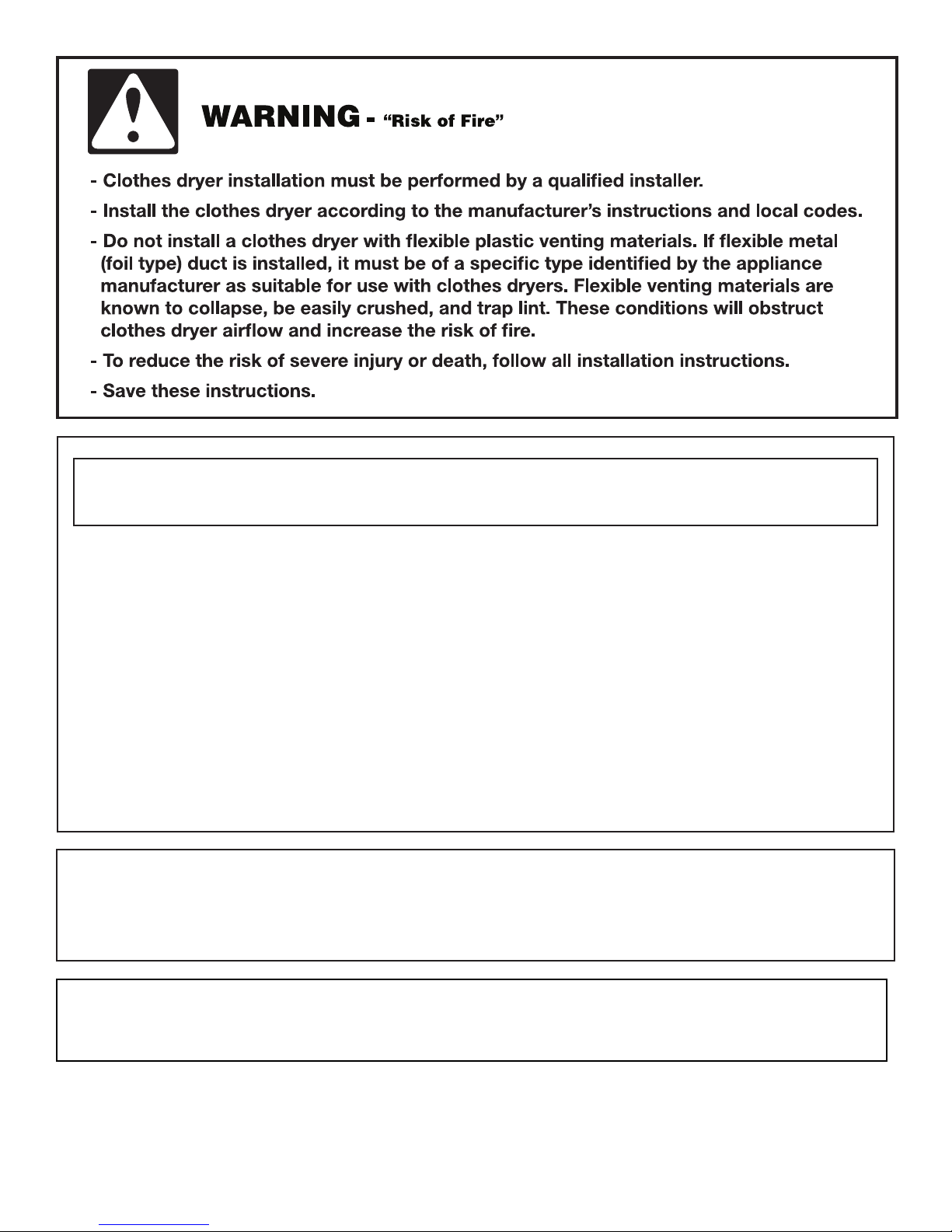
You can be killed or seriously injured if you don't immediately
You
can be killed or seriously injured if you don't
follow
All safety messages will tell you what the potential hazard is, tell you how to reduce the chance of injury, and tell you what can
happen if the instructions are not followed.
Your safety and the safety of others are very important.
We have provided many important safety messages in this manual and on your appliance. Always read and obey all safety
messages.
This is the safety alert symbol.
This symbol alerts you to potential hazards that can kill or hurt you and others.
All safety messages will follow the safety alert symbol and either the word “DANGER” or “WARNING.”
These words mean:
follow instructions.
instructions.
DANGER
WARNING
TABLE OF CONTENTS
TABLE DES MATIÈRES
DRYER SAFETY............................................................................ 2
INSTALLATION REQUIREMENTS .............................................. 5
Tools and Parts.......................................................................... 5
Location Requirements.............................................................. 5
Electrical Requirements - Gas Dryer ........................................ 7
Electrical Requirements - Electric Dryer (U.S.A. Only) ............ 8
Electrical Requirements - Electric Dryer (Canada Only) .......... 9
as Supply Requirements .................................................... 10
G
Venting Requirements ............................................................ 11
INSTALLATION INSTRUCTIONS – COIN SLIDE
AND COIN BOX ...................................................................... 12
INSTALLATION INSTRUCTIONS – GAS DRYER .................. 13
Make Gas Connection..............................................................13
Connect Vent ............................................................................13
Complete Installation ..............................................................13
INSTALLATION INSTRUCTIONS – ELECTRIC DRYER........ 14
Make Electrical Connection......................................................14
Connect Vent ............................................................................18
Complete Installation ..............................................................18
CHANGING TO A 30- OR 60-MINUTE TIMING CAM .......... 19
REVERSING THE DOOR SWING .......................................... 19
MAINTENANCE INSTRUCTIONS ..........................................20
WARRANTY..............................................................................21
SÉCURITÉ DE LA SÉCHEUSE ..............................................22
EXIGENCES D’INSTALLATION................................................25
Outillage et pièces ....................................................................25
Exigences d’emplacement ......................................................26
Spécifications électriques - sécheuse à gaz ...........................27
Spécifications électriques - Pour le Canada seulement .........28
Spécifications de l’alimentation en gaz ..................................29
xigences concernant l'évacuation..........................................30
E
INSTALLATION D’UNE GLISSIÈRE
ET D’UNE CAISSE À MONNAIE ..............................................32
INSTRUCTIONS D’INSTALLATION – SÉCHEUSE À GAZ ....32
Raccordement à la canalisation de gaz ..................................32
Raccordement du conduit d'évacuation ................................32
Achever l’installation ................................................................33
INSTRUCTIONS D’INSTALLATION – SÉCHEUSE
ÉLECTRIQUE............................................................................33
Raccordement du conduit d'évacuation ................................33
Achever l’installation ................................................................34
INSTALLATION D’UNE CAME DE MINUTAGE DE 30 OU 60
MINUTES......................................................................................34
INVERSION DU SENS D’OUVERTURE DE LA PORTE............35
INSTRUCTIONS D’ENTRETIEN..................................................35
GARANTIE ....................................................................................36
DRYER SAFETY
2
WARNING: For your safety, the information in this manual must be followed to minimize
the risk of fire or explosion, or to prevent property damage, personal injury, or death.
– Do not store or use gasoline or other flammable vapors and liquids in the vicinity of this
or any other appliance.
– WHAT TO DO IF YOU SMELL GAS:
•
Do not try to light any appliance.
•
Do not touch any electrical switch; do not use any phone in your building.
•
Immediately call your gas supplier from a neighbor's phone. Follow the gas supplier's
instructions.
•
If you cannot reach your gas supplier, call the fire department.
– Installation and service must be performed by a qualified installer, service agency, or
the gas supplier.
•
Clear the room, building, or area of all occupants.
WARNING: Gas leaks cannot always be detected by smell.
Gas suppliers recommend that you use a gas detector approved by UL or CSA.
For more information, contact your gas supplier.
If a gas leak is detected, follow the “What to do if you smell gas” instructions.
IMPORTANT: The gas installation must conform with local codes, or in the absence of local codes, with the National Fuel Gas
Code, ANSI Z223.1/NFPA 54 or the Canadian Natural Gas and Propane Installation Code, CSA B149.1.
The dryer must be electrically grounded in accordance with local codes, or in the absence of local codes, with the National
Electrical Code, ANSI/NFPA 70 or Canadian Electrical Code, CSA C22.1.
3

FOR YOUR SAFETY
Do not store or use gasoline or other flammable vapors and liquids in the vicinity of this or any other appliance.
■ It is recommended that the owner post, in a prominent location, instructions for the customer’s use in the event the customer smells
In the State of Massachusetts, the following installation instructions apply:
■ Installations and repairs must be performed by a qualified or licensed contractor, plumber, or gasfitter qualified or licensed by
the State of Massachusetts.
■ If using a ball valve, it shall be a T-handle type.
■ A flexible gas connector, when used, must not exceed 3 feet.
gas. This information should be obtained from your gas supplier.
■ Post the following warning in a prominent location.
4
INSTALLATION REQUIREMENTS
Tools and Parts
Gather the required tools and parts before starting installation.
Read and follow the instructions provided with any tools
listed here.
ools needed
T
■ 8" (20 cm) or 10" (25 cm) Pipe wrench
" (20 cm) or 10" (25 cm) adjustable wrench
■ 8
■ Flat-blade screwdriver
■ Phillips screwdriver
■ Adjustable wrench that opens to 1" (25 mm) or 1" (25 mm)
hex-head socket wrench
■ Level
5
■
⁄16" socket wrench
■ Utility knife
■ Vent clamps
■ Pipe-joint compound resistant to LP gas
■ Caulk gun and caulk (for installing new exhaust vent)
■ Pliers
■ Putty knife
Parts supplied
Remove parts bag from dryer drum. Check that all parts were
included.
■ Wedge Cone
■ Foot boot (4)
■ Dryer foot (4)
5
■
⁄16-18 x 21⁄2" bolt
■ 3 pin timing cam
■ 6 pin timing cam
Location Requirements
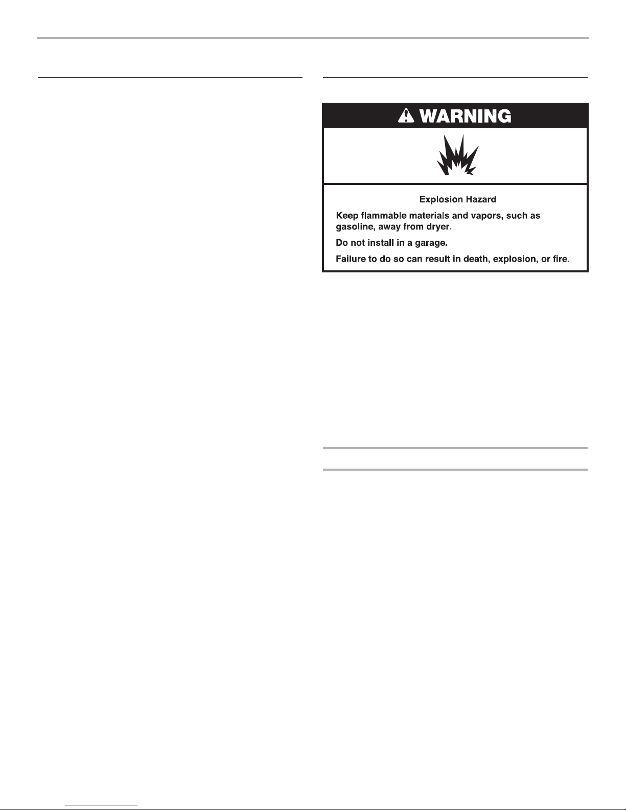
If installing a gas dryer:
IMPORTANT: Observe all governing codes and ordinances.
■ Check code requirements: Some codes limit or do not permit
installation of clothes dryers in garages, closets, or sleeping
quarters. Contact your local building inspector.
■ Make sure that lower edges of the cabinet, plus the back and
bottom sides of the dryer, are free of obstructions to permit
adequate clearance of air openings for combustion air. See
“Recessed Area and Closet Installation Instructions” below
for minimum spacing requirements.
NOTE: The dryer must not be installed in an area where it will
be exposed to water and/or weather.
Recessed Area and Closet Installation Instructions
This dryer may be installed in a recessed area or closet.
For recessed area and closet installations, minimum clearances
can be found on the warning label on the rear of the dryer.
The installation spacing is in inches and is the minimum
allowable. Additional spacing should be considered for ease
of installation, servicing, and compliance with local codes
and ordinances.
If closet door is installed, the minimum unobstructed air opening
in the top and bottom is required. Louvered doors with equivalent
air openings are acceptable.
The dryer must be exhausted outdoors.
No other fuel-burning appliance may be installed in the same
closet as the dryer.
5
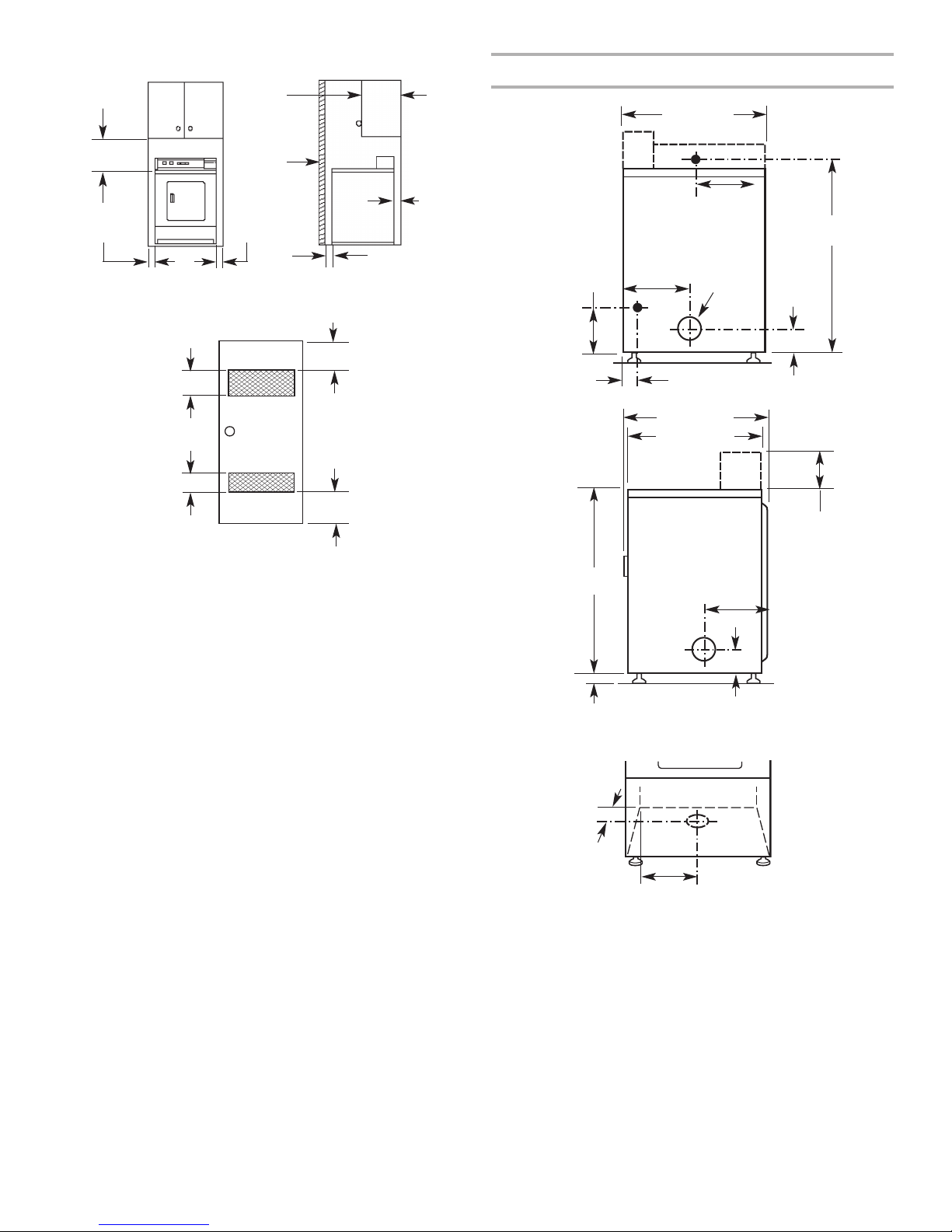
Minimum Installation Clearances
4"
1
356 mm)
(
ax.
m
Product Dimensions 27" (686 mm) dryer
7" (686 mm)
2
15"
(381 mm)*
" (0 mm)
0
" (0 mm)
0
Closet
door
1" (25 mm)
Recessed front view Closet side view
dditional clearances for wall, door and floor moldings may be required or if
A
xternal exhaust elbow is used.
e
" (76 mm)
2
48 in
(310 cm2)*
ront
F
View
24 in
2
closet
oor
d
(155 cm2)*
*Opening is the minimum for a closet door.
Louvered doors with equivalent air openings are acceptable.
3
3" (76 mm)
"
0
0 mm)
(
63⁄4"
152 mm)
(
11⁄4"
(32 mm)
(889 mm)
35"
LECTRIC
E
ACK VIEW
B
13"
(330 mm)
GAS
291⁄4" (743 mm)
1
6
2
⁄2"
SIDE VIEW
LEFT OR
RIGHT SIDE
EXHAUST
4"
1
35.6 cm)
(
4" (102 mm)
dia.
EXHAUST
(673 mm)
101⁄4"
(260 mm)
37"
(940 mm)
3
⁄4"
4
(121 mm)
Non-coin-
operated models:
1
⁄8" (181 mm)
7
Coin-operated
models:
7
⁄8" (200 mm)
7
3
⁄4"
(21 mm)
71⁄4"
(184 mm)
41⁄4"
(108 mm)
BOTTOM
EXHAUST
141⁄8"
(359 mm)
6
Electrical Requirements – Gas Dryer
IMPORTANT: The dryer must be electrically grounded in
accordance with local codes and ordinances or, in the absence of
local codes, with the National Electrical Code, ANSI/NFPA 70,
latest edition, or Canadian Electrical Code, CSA C22.1.
If codes permit and a separate ground wire is used, it is
recommended that a qualified electrical installer determine that
the ground path is adequate.
A copy of the above code standards can be obtained from:
National Fire Protection Association
One Batterymarch Park, Quincy, MA 02269
CSA International
8501 East Pleasant Valley Road
Cleveland, Ohio 44131-5575
■ A 120 volt, 60 Hz, AC only, 15- or 20-amp, fused electrical
circuit is required. A time-delay fuse or circuit breaker is also
recommended. It is recommended that a separate circuit
serving only this dryer be provided.
Recommended Ground Method
The dryer, when installed, must be electrically grounded in
accordance with local codes or, in the absence of local codes,
ith the National Electrical Code, ANSI/NFPA 70, latest edition,
w
or Canadian Electrical Code, CSA C22.1, and all local codes
and ordinances.
7
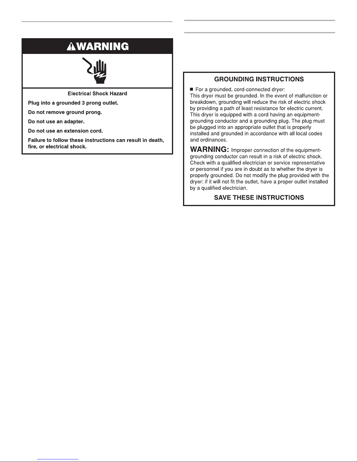
Electrical Requirements – U.S.A. Only
If using a power supply cord:
It is your responsibility
■ To contact a qualified electrical installer.
■ To be sure that the electrical connection is adequate and in
conformance with the National Electrical Code, ANSI/NFPA
70-latest edition and all local codes and ordinances.
The National Electrical Code requires a 4-wire power supply
connection for homes built after 1996, dryer circuits involved
in remodeling after 1996, and all mobile home installations.
copy of the above code standards can be obtained from:
A
National Fire Protection Association, One Batterymarch Park,
Quincy, MA 02269.
■ To supply the required 3 or 4 wire, single phase, 120/240 volt,
60 Hz., AC only electrical supply (or 3 or 4 wire, 120/208 volt
electrical supply, if specified on the serial/rating plate) on a
separate 30-amp circuit, fused on both sides of the line. A
time-delay fuse or circuit breaker is recommended. Connect
to an individual branch circuit. Do not have a fuse in the
neutral or grounding circuit.
■ Do not use an extension cord.
■ If codes permit and a separate ground wire is used, it is
recommended that a qualified electrician determine that the
ground path is adequate.
Electrical Connection
Use a UL listed power supply cord kit marked for use with
clothes dryers. The kit should contain:
■ A UL listed 30-amp power supply cord, rated 120/240 volt
minimum. The cord should be type SRD or SRDT and be at
least 4 ft (1.22 m) long. The wires that connect to the dryer
must end in ring terminals or spade terminals with upturned
ends.
■ A UL listed strain relief.
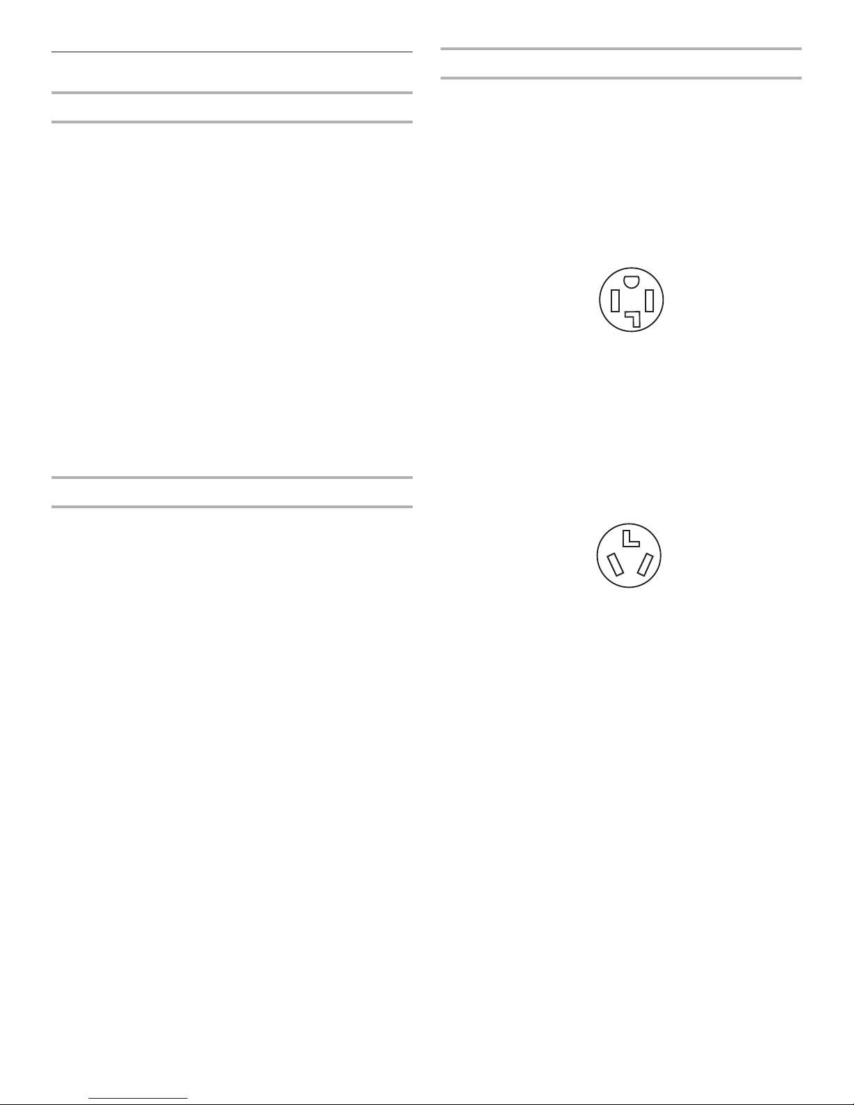
If your outlet looks like this:
4-wire receptacle (14-30R)
Then choose a 4-wire power supply cord with ring or spade
terminals and UL listed strain relief. The 4-wire power supply
cord, at least 4 ft (1.22 m) long, must have four 10-gauge copper
wires and match a 4-wire receptacle of NEMA Type 14-30R. The
ground wire (ground conductor) may be either green or bare. The
neutral conductor must be identified by a white cover.
If your outlet looks like this:
To properly install your dryer, you must determine the type of
electrical connection you will be using and follow the instructions
provided for it here.
■ This dryer is manufactured ready to install with a 3-wire
electrical supply connection. The neutral ground conductor is
permanently connected to the neutral conductor (white wire)
within the dryer. If the dryer is installed with a 4-wire electrical
supply connection, the neutral ground conductor must be
removed from the external ground connector (green screw),
and secured under the neutral terminal (center or white wire)
of the terminal block. When the neutral ground conductor is
secured under the neutral terminal (center or white wire) of the
terminal block, the dryer cabinet is isolated from the neutral
conductor.
■ If local codes do not permit the connection of a neutral
ground wire to the neutral wire, see “Optional 3-wire
connection” section.
■ A 4-wire power supply connection must be used when the
appliance is installed in a location where grounding through
the neutral conductor is prohibited. Grounding through the
neutral is prohibited for (1) new branch-circuit installations, (2)
mobile homes, (3) recreational vehicles, and (4) areas where
local codes prohibit grounding through the neutral conductor.
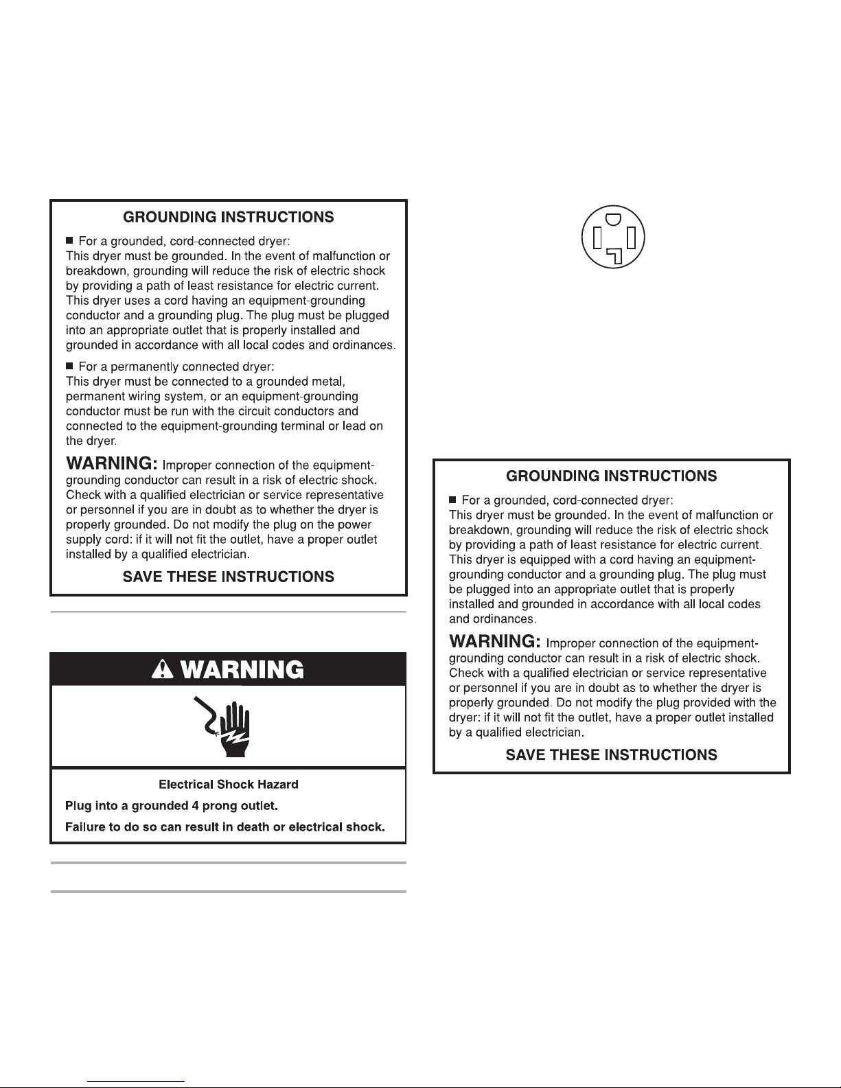
3-wire receptacle (10-30R)
Then choose a 3-wire power supply cord with ring or spade
terminals and UL listed strain relief. The 3-wire power supply
cord, at least 4 ft (1.22 m) long, must have three 10-gauge copper
wires and match a 3-wire receptacle of NEMA Type 10-30R.
8
If connecting by direct wire:
Power supply cable must match power supply (4-wire or 3-wire)
and be:
■ Flexible armored cable or nonmetallic sheathed copper cable
(with ground wire), protected with flexible metallic conduit. All
current-carrying wires must be insulated.
10-gauge solid copper wire (do not use aluminum).
■
■ At least 5 ft (1.52 m) long.
■ To supply the required 4 wire, single phase, 120/240 volt,
60 Hz., AC only electrical supply on a separate 30-amp
circuit, fused on both sides of the line. A time-delay fuse or
circuit breaker is recommended. Connect to an individual
branch circuit.
■ This dryer is equipped with a CSA International Certified
Power Cord intended to be plugged into a standard 14-30R
wall receptacle. The cord is 5 ft (1.52 m) in length. Be sure
wall receptacle is within reach of dryer’s final location.
4-wire receptacle (14-30R)
■ Do not use an extension cord.
If you are using a replacement power supply cord, it is
recommended that you use Power Supply Cord Replacement
Part Number 9831317. For further information, please
reference the service numbers located in the “Assistance
or Service” section.
Electrical Requirements – Canada Only
It is your responsibility
■ To contact a qualified electrical installer.
■ To be sure that the electrical connection is adequate and in
conformance with the Canadian Electrical Code, C22.1-latest
edition and all local codes. A copy of the above codes
standard may be obtained from: Canadian Standards
Association, 178 Rexdale Blvd., Toronto, ON M9W 1R3
CANADA.
9
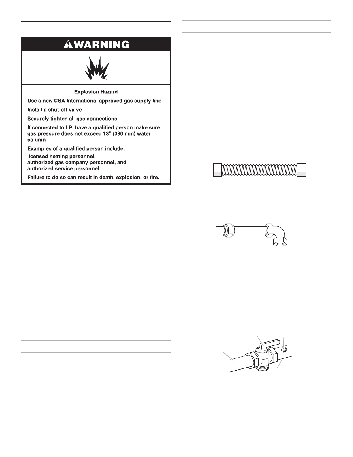
D
B
C
A
Gas Supply Requirements
IMPORTANT: Observe all governing codes and ordinances.
This installation must conform with all local codes and
ordinances. In the absence of local codes, installation must
conform with American National Standard, National Fuel Gas
Code ANSI Z223.1/NFPA 54 or CAN/CSA B149.
A copy of the above code standards can be obtained from:
National Fire Protection Association
One Batterymarch Park, Quincy, MA 02269
CSA International
8501 East Pleasant Valley Road
Cleveland, Ohio 44131-5575
The design of this dryer has been certified by CSA International
for use at altitudes up to 10,000 feet (3048 m) above sea level at
the B.T.U. rating indicated on the model/serial plate. Burner input
adjustments are not required when the dryer is operated up to
this elevation.
When installed above 10,000 feet (3048 m), a four percent (4%)
reduction of the burner B.T.U. rating shown on the model/serial
plate is required for each 1,000 foot (305 m) increase in elevation.
For assistance when converting to other gas types and/or
installing above 10,000 feet (3048 m) elevation, contact your
local service company.
Gas Supply Line
Recommended method
1
■ Provide a gas supply line of
location. Pipe joint compounds that resist the action of LP gas
ust be used. Do not use TEFLON
m
piping or tubing size can be
suppliers determine the size and materials used in the system.
Alternate method
■ The gas supply may also be connected using3⁄8" approved
opper or aluminum tubing. If the total length of the supply
c
line is more than 20 ft. (6.1 m), larger tubing will be required.
If using natural gas, do not use copper tubing. Pipe joint
ompounds that resist the action of LP gas must be used.
c
lexible metal appliance connector:
F
■ It is recommended that a new flexible stainless steel gas line,
design-certified by CSA International, be used for connecting
the dryer to the gas supply line. (The gas pipe which extends
through the lower rear of the dryer is provided with
pipe thread.)
■ Do not kink or damage the flexible stainless steel gas line
when moving the dryer.
Rigid pipe connection:
The rigid pipe connection requires a combination of pipe fittings
to obtain an in-line connection to the dryer.
■ Must include a shutoff valve:
The supply line must be equipped with a manual shutoff
valve installed within 6 ft. (1.8 m) of dryer in accordance
with National Fuel Gas Code, ANSI Z223.1. In Canada,
an individual manual shutoff valve must be installed in
accordance with the B149 installation codes CAN/CGA
B149.1 and CAN/CGA B149.2. This valve should be located
in the same room as the dryer. It should be in a location that
allows ease of opening and closing. Do not block access to
shutoff valve. The valve is for turning on or shutting off gas
to the dryer.
⁄2" rigid (IPS) pipe to the dryer
®†
ape. With LP gas,
1
⁄2" minimum. Usually, LP gas
t
3
⁄8" male
Type of Gas
This dryer is equipped for use with natural gas. It is designcertified by CSA International for LP (propane and butane) gases
with appropriate conversion. No attempt shall be made to convert
the dryer from the gas specified on the serial/rating plate for use
with a different gas without consulting the serving gas supplier.
Conversion must be done by a qualified service technician.
Gas conversion kit part numbers are listed on the gas valve
burner base.
10
A. Gas supply line
B. Shutoff valve in “open” position
C. To dryer
D. NPT 1/8" min. plugged tapping
†®TEFLON is a registered trademark of E.I. Du Pont De Nemours and Company.

■ Installed in a confined area:
If the dryer is installed in a confined area such as a bathroom
or closet, provision must be made for enough air for
combustion and ventilation. Check governing codes and
ordinances or refer to the “Recessed Area and Closet
Installation Instructions” in the “Location Requirements”
section.
Gas Supply Pressure Testing
A1⁄8" NPT minimum plugged tapping, accessible for gauge
testing, must be installed immediately upstream of the installed
shut-off valve to the dryer.
The dryer must be disconnected from the gas supply piping
system during any pressure testing of the system at test
ressures in excess of
p
1
psig.
⁄2"
Venting Requirements
Exhaust hood must be at least 12" (305 mm) from the ground
or any object that may be in the path of the exhaust (such as
flowers, rocks, or bushes).
If using an existing vent system, clean lint from the entire length
of the system and make sure exhaust hood is not plugged with
lint. Replace any plastic or metal foil vent with rigid metal or
flexible metal vent.
lan installation to use the fewest number of elbows and turns.
P
A
Exhaust Air Flow
A. Good
B. Better
B
Allow as much room as possible when using elbows or making
turns. Bend vent gradually to avoid kinking.
Vent outlet is located at the back of the dryer, at bottom center.
The vent can be routed up, down, left, right, or straight out the
back of the dryer.
WARNING: To reduce the risk of fire, this dryer MUST BE
EXHAUSTED OUTDOORS.
■ The dryer vent must not be exhausted into any gas vent,
chimney, wall, ceiling, attic, crawlspace, or a concealed space
of a building.
■ Only rigid or flexible metal duct shall be used for exhausting.
■ Do not use an exhaust hood with a magnetic latch.
■ Do not install flexible metal vent in enclosed walls, ceilings,
or floors.
■ 4" (102 mm) heavy metal vent and clamps must be used. Do
not use plastic or metal foil vent.
■ Use clamps to seal all joints. The duct shall not be assembled
with screws or other fastening means that extend into the
duct and catch lint. Do not use duct tape.
3
■ The total length of flexible metal vent shall not exceed 7
(2.4 m).
IMPORTANT: Observe all governing codes and ordinances.
Rigid metal vent is recommended to prevent crushing and
kinking.
Flexible metal vent must be fully extended and supported when
the dryer is in its final position. Remove excess flexible metal vent
to avoid sagging and kinking that may result in reduced airflow
and poor performance.
An exhaust hood should cap the vent to prevent rodents and
insects from entering the home or business.
⁄4 ft
Vent System Length
Maximum length of vent system depends upon the type of
vent used, number of elbows, and type of exhaust hood.
The maximum length for rigid vent is shown in the chart.
Maximum Vent Length
4" (102 mm) Diameter Exhaust Hoods
Rigid Metal Vent
No. of 90° turns
0
1
2
3
4
For vent systems not covered by the vent specification chart,
see your parts distributor.
If dryer is installed in a confined area, such as a bedroom,
bathroom, or closet, provision must be made for enough air
for combustion and ventilation. (Check governing codes and
ordinances.) See “Recessed Area and Closet Installation
Instructions” in the “Location Requirements” section.
A 4" (102 mm) outlet hood is preferred. However, a 2
outlet exhaust hood may be used. A 2
greater back pressure than other hood types. For permanent
installation, a stationary vent system is required.
Box Hood and Louvered Style Angled Hood Style
64 ft. (19.5 m)
54 ft. (16.5 m)
44 ft. (13.4 m)
35 ft. (10.7 m)
27 ft. (8.2 m)
1
⁄2" (64 mm) outlet creates
58 ft. (17.7 m)
48 ft. (14.6 m)
38 ft. (11.6 m)
29 ft. (8.8 m)
21 ft. (6.4 m)
1
⁄2" (64 mm)
11
 Loading...